EP2894095A1 - Constant velocity drive for tilt rotor assembly - Google Patents
Constant velocity drive for tilt rotor assembly Download PDFInfo
- Publication number
- EP2894095A1 EP2894095A1 EP14192827.5A EP14192827A EP2894095A1 EP 2894095 A1 EP2894095 A1 EP 2894095A1 EP 14192827 A EP14192827 A EP 14192827A EP 2894095 A1 EP2894095 A1 EP 2894095A1
- Authority
- EP
- European Patent Office
- Prior art keywords
- drive
- ring
- driven
- bearing
- rotor
- Prior art date
- Legal status (The legal status is an assumption and is not a legal conclusion. Google has not performed a legal analysis and makes no representation as to the accuracy of the status listed.)
- Granted
Links
- 230000000712 assembly Effects 0.000 description 2
- 238000000429 assembly Methods 0.000 description 2
- 230000004075 alteration Effects 0.000 description 1
- 230000008602 contraction Effects 0.000 description 1
- 238000005516 engineering process Methods 0.000 description 1
- 230000007246 mechanism Effects 0.000 description 1
- 230000000717 retained effect Effects 0.000 description 1
- 238000006467 substitution reaction Methods 0.000 description 1
Images




Classifications
-
- B—PERFORMING OPERATIONS; TRANSPORTING
- B64—AIRCRAFT; AVIATION; COSMONAUTICS
- B64C—AEROPLANES; HELICOPTERS
- B64C27/00—Rotorcraft; Rotors peculiar thereto
- B64C27/04—Helicopters
- B64C27/12—Rotor drives
- B64C27/14—Direct drive between power plant and rotor hub
-
- B—PERFORMING OPERATIONS; TRANSPORTING
- B64—AIRCRAFT; AVIATION; COSMONAUTICS
- B64C—AEROPLANES; HELICOPTERS
- B64C27/00—Rotorcraft; Rotors peculiar thereto
- B64C27/04—Helicopters
- B64C27/06—Helicopters with single rotor
-
- B—PERFORMING OPERATIONS; TRANSPORTING
- B64—AIRCRAFT; AVIATION; COSMONAUTICS
- B64C—AEROPLANES; HELICOPTERS
- B64C27/00—Rotorcraft; Rotors peculiar thereto
- B64C27/32—Rotors
-
- B—PERFORMING OPERATIONS; TRANSPORTING
- B64—AIRCRAFT; AVIATION; COSMONAUTICS
- B64C—AEROPLANES; HELICOPTERS
- B64C27/00—Rotorcraft; Rotors peculiar thereto
- B64C27/32—Rotors
- B64C27/35—Rotors having elastomeric joints
-
- B—PERFORMING OPERATIONS; TRANSPORTING
- B64—AIRCRAFT; AVIATION; COSMONAUTICS
- B64C—AEROPLANES; HELICOPTERS
- B64C27/00—Rotorcraft; Rotors peculiar thereto
- B64C27/32—Rotors
- B64C27/37—Rotors having articulated joints
- B64C27/41—Rotors having articulated joints with flapping hinge or universal joint, common to the blades
-
- F—MECHANICAL ENGINEERING; LIGHTING; HEATING; WEAPONS; BLASTING
- F16—ENGINEERING ELEMENTS AND UNITS; GENERAL MEASURES FOR PRODUCING AND MAINTAINING EFFECTIVE FUNCTIONING OF MACHINES OR INSTALLATIONS; THERMAL INSULATION IN GENERAL
- F16D—COUPLINGS FOR TRANSMITTING ROTATION; CLUTCHES; BRAKES
- F16D3/00—Yielding couplings, i.e. with means permitting movement between the connected parts during the drive
- F16D3/50—Yielding couplings, i.e. with means permitting movement between the connected parts during the drive with the coupling parts connected by one or more intermediate members
-
- F—MECHANICAL ENGINEERING; LIGHTING; HEATING; WEAPONS; BLASTING
- F16—ENGINEERING ELEMENTS AND UNITS; GENERAL MEASURES FOR PRODUCING AND MAINTAINING EFFECTIVE FUNCTIONING OF MACHINES OR INSTALLATIONS; THERMAL INSULATION IN GENERAL
- F16D—COUPLINGS FOR TRANSMITTING ROTATION; CLUTCHES; BRAKES
- F16D3/00—Yielding couplings, i.e. with means permitting movement between the connected parts during the drive
- F16D3/16—Universal joints in which flexibility is produced by means of pivots or sliding or rolling connecting parts
- F16D3/26—Hooke's joints or other joints with an equivalent intermediate member to which each coupling part is pivotally or slidably connected
- F16D3/30—Hooke's joints or other joints with an equivalent intermediate member to which each coupling part is pivotally or slidably connected in which the coupling is specially adapted to constant velocity-ratio
-
- F—MECHANICAL ENGINEERING; LIGHTING; HEATING; WEAPONS; BLASTING
- F16—ENGINEERING ELEMENTS AND UNITS; GENERAL MEASURES FOR PRODUCING AND MAINTAINING EFFECTIVE FUNCTIONING OF MACHINES OR INSTALLATIONS; THERMAL INSULATION IN GENERAL
- F16D—COUPLINGS FOR TRANSMITTING ROTATION; CLUTCHES; BRAKES
- F16D3/00—Yielding couplings, i.e. with means permitting movement between the connected parts during the drive
- F16D3/50—Yielding couplings, i.e. with means permitting movement between the connected parts during the drive with the coupling parts connected by one or more intermediate members
- F16D3/70—Yielding couplings, i.e. with means permitting movement between the connected parts during the drive with the coupling parts connected by one or more intermediate members comprising elastic elements arranged in holes in one coupling part and surrounding pins on the other coupling part
Definitions
- the subject matter disclosed herein generally relates to rotors for aircraft use. More specifically, the subject disclosure relates to tilting rotors for helicopters or other rotorcraft.
- a rotor assembly In helicopters or other rotorcraft, a rotor assembly has an axis of rotation, and a plurality of radially extending rotor blades rotating in a plane of rotation. This plane of rotation is nominally perpendicular to the axis of rotation. In some rotorcraft, and under certain operating conditions, it is desired to tilt the plane of rotation so it is no longer perpendicular to the axis of rotation.
- Rotor assemblies with this capability are often called gimbal rotors and are used in both conventional helicopter applications as a main rotor or as a rotor/propeller in a tilt wing or tilt rotor vertical takeoff and landing (VTOL) aircraft.
- VTOL tilt rotor vertical takeoff and landing
- a constant velocity joint is utilized to connect the rotor shaft to the rotor assembly to allow the rotor to tilt while maintaining a constant rotational velocity.
- Previous configurations of such constant velocity joints are complex and have a large envelope and typically increase system weight significantly.
- a constant velocity drive includes a drive ring having a drive ring axis of rotation and a driven ring positioned around the drive ring and which is driven by the drive ring to rotate about a driven ring axis of rotation.
- a plurality of drive links extend from the drive ring to the driven ring to transfer torque applied at the drive ring to the driven ring.
- a plurality of elastomeric bearings are positioned at the driven ring to transfer torque from one of the plurality of drive links to the driven ring.
- Each elastomeric bearing includes both spherical bearing elements and planar bearing elements to allow for tilt of the driven ring axis of rotation with respect to the drive ring axis of rotation while ensuring a constant rotational velocity of the driven ring with respect to the rotational velocity of the drive ring.
- each elastomeric bearing may include an intermediate race separating the spherical bearing elements from the planar bearing elements.
- each elastomeric bearing may include an inner bearing race interfacing with the respective drive link of the plurality of drive links, the spherical bearing elements located between the inner bearing race and the intermediate race.
- each elastomeric bearing may include an outer bearing race interfacing with the driven ring, the planar bearing elements located between the outer bearing race and the intermediate race.
- a gimbal bearing may be connected to the driven ring which reacts the tilt of the driven ring relative to the drive ring.
- a rotor assembly may include a rotor hub and a plurality of rotor blades extending radially outwardly from the rotor hub.
- a constant velocity drive may operably connect the rotor hub to a rotor shaft and may include a drive ring having a drive ring axis of rotation and which is operably connectible to the rotor shaft.
- a plurality of drive links may extend from the drive ring toward the rotor hub to transfer torque applied at the drive ring to the rotor hub.
- a plurality of elastomeric bearings may operably be connected to the rotor hub to transfer torque from one of the plurality of drive links to the rotor hub.
- Each elastomeric bearing may include both spherical bearing elements and planar bearing elements to allow for tilt of an axis of rotation of the rotor hub with respect to the drive ring axis of rotation while ensuring a constant rotational velocity of the rotor hub with respect to the rotational velocity of the drive ring.
- a driven ring may be secured to the rotor hub and is positioned between the rotor hub and the drive ring and driven by the drive ring to rotate about a driven ring axis of rotation.
- the plurality of elastomeric bearings may be located at the driven ring.
- a gimbal bearing may be connected to the driven ring and may react the tilt of the driven ring relative to the drive ring.
- each elastomeric bearing may include an intermediate race separating the spherical bearing elements from the planar bearing elements.
- each elastomeric bearing may include an inner bearing race interfacing with the respective drive link of the plurality of drive links, the spherical bearing elements located between the inner bearing race and the intermediate race.
- each elastomeric bearing includes an outer bearing race, the planar bearing elements located between the outer bearing race and the intermediate race.
- a rotorcraft may include an airframe and a drive system disposed at the airframe.
- the drive system may include a drive shaft rotating about a shaft axis.
- a rotor assembly may be operably connected to the drive system and may include a rotor hub and a plurality of rotor blades extending radially outwardly from the rotor hub.
- a constant velocity drive may operably connect the rotor hub to the rotor shaft and may include a drive ring having a drive ring axis of rotation and which is operably connectible to the rotor shaft.
- a plurality of drive links may extend from the drive ring toward the rotor hub to transfer torque applied at the drive ring to the rotor hub.
- a plurality of elastomeric bearings may operably be connected to the rotor hub to transfer torque from one of the plurality of drive links to the rotor hub.
- Each elastomeric bearing may include both spherical bearing elements and planar bearing elements to allow for tilt of an axis of rotation of the rotor hub with respect to the drive ring axis of rotation while ensuring a constant rotational velocity of the rotor hub with respect to the rotational velocity of the drive ring.
- a driven ring may be secured to the rotor hub and may bepositioned between the rotor hub and the drive ring and driven by the drive ring to rotate about a driven ring axis of rotation.
- the plurality of elastomeric bearings may be located at the driven ring.
- a gimbal bearing may be connected to the driven ring and may react the tilt of the driven ring relative to the drive ring.
- each elastomeric bearing may include an intermediate race separating the spherical bearing elements from the planar bearing elements.
- each elastomeric bearing may include an inner bearing race interfacing with the respective drive link of the plurality of drive links, the spherical bearing elements positioned between the inner bearing race and the intermediate race.
- each elastomeric bearing may include an outer bearing race, the planar bearing elements located between the outer bearing race and the intermediate race.
- FIG. 1 Shown in FIG. 1 is schematic view of an embodiment of rotorcraft, in this embodiment a helicopter 10.
- the helicopter 10 includes an airframe 12 with an extending tail 14 and a tail rotor 16 located thereat. While the embodiment of a helicopter 10 described herein includes an extending tail 14 and tail rotor 16, it is to be appreciated that the disclosure herein may be applied to other types of rotor craft, such as tilt wing or tilt rotor vertical takeoff and landing (VTOL) aircraft.
- a main rotor assembly 18 is located at the airframe 12 and is driven by a rotor shaft 22 rotating about a rotor axis 20.
- the rotor shaft 22 is connected to a power source, for example, an engine 24 by a gearbox 26.
- the main rotor assembly 18 rotates in a rotation plane 28 nominally perpendicular to the rotor axis 20.
- the main rotor assembly 18 includes a gimbal bearing 30 allowing for tilt of the rotation plane 28 as desired relative to the rotor axis 20, as shown in FIG. 3 , so that the rotation plane 28 is no longer perpendicular to the rotor axis 20.
- the rotor assembly 18 is connected to the rotor shaft 22 by a constant velocity drive 32.
- the rotor assembly 18 includes a rotor hub 34 with a plurality of rotor blades 36 extending radially outwardly from the rotor hub 34.
- the gimbal bearing 30 and the constant velocity drive 32 are secured to the rotor hub 34 to allow for tilt thereof.
- the gimbal bearing 30 is further secured to the rotor shaft 22, although it is understood that the gimbal bearing 30 could also be attached to the drive ring 38.
- the constant velocity drive 32 (hereinafter referred to as "drive 32”) includes a drive ring 38 connected to the rotor shaft 22 via a drive spline 40 or other suitable connection and retained axially by a retaining ring 42.
- the drive 32 further includes a driven ring 44 fixed to the rotor hub 34 and three or more drive links 46 extending between the drive ring 38 and the driven ring 44.
- each drive link 46 is secured to the drive ring 38 at a clevis 48 of the drive ring 38, with a pin 50 extending through the clevis 48 allowing for rotation of the drive link 46 about a pin axis 52.
- Torque is transmitted from the rotor shaft 22 to the drive ring 38 via the drive spline 40, and from the drive ring 38 to the drive links 46 via the clevis 48.
- the clevis 48 has two prongs extending from the ring 38 through which the pin 50 extends to rotatably couple the drive ring 38 and the drive link 46.
- other attachment mechanisms can be used, such as where the clevis 48 has fewer or more prongs than what is shown in the exemplary embodiment.
- each drive link 46 extends to the driven ring 44 and is supported at the driven ring 44 by an elastomeric bearing 54, through which torque is transmitted from the drive links 46 to the driven ring 44.
- the elastomeric bearing 54 shown also in the partially exploded view of FIG. 6 , includes an inner race 56 forming the interface with the drive link 46, and an outer race 58 to interface with the driven ring 44.
- the outer race 58 is square or rectangular and fits into a bearing opening 60 in the driven ring 44, although the particular shape is not so limited according to the shape of the opening 60.
- the elastomeric bearing 54 includes both spherical elements 62 and flat plate elements 64.
- the spherical elements 62 and the flat plate elements, or planar elements 64 are separated by an intermediate race 66, with the spherical elements 62 positioned between the inner race 56 and the intermediate race 66 and the planar elements 64 positioned between the intermediate race 66 and the outer race 68.
- the spherical elements 62 accommodate the tilt of the rotor assembly 18, while the planar elements 64 allow for the foreshortening on a distance between the driven ring 44 and the drive ring 42 due to the tilt.
- a center-to-center distance between the spherical portions of the elastomeric bearings 54 varies as the rotor hub 34 and rotor shaft 22 rotate about their respective axes. This expansion and contraction of the center-to-center distance results in a forced tangential deflection of each elastomeric bearing 54. As each elastomeric bearing 54 has the same spring rate, the tangential deflection is equally shared by the three elastomeric bearings 54. This equalization of deflections ensures a constant velocity joint between the rotor hub 34 and the rotor shaft 22.
Landscapes
- Engineering & Computer Science (AREA)
- Mechanical Engineering (AREA)
- Aviation & Aerospace Engineering (AREA)
- General Engineering & Computer Science (AREA)
- Support Of The Bearing (AREA)
Abstract
Description
- The subject matter disclosed herein generally relates to rotors for aircraft use. More specifically, the subject disclosure relates to tilting rotors for helicopters or other rotorcraft.
- In helicopters or other rotorcraft, a rotor assembly has an axis of rotation, and a plurality of radially extending rotor blades rotating in a plane of rotation. This plane of rotation is nominally perpendicular to the axis of rotation. In some rotorcraft, and under certain operating conditions, it is desired to tilt the plane of rotation so it is no longer perpendicular to the axis of rotation. Rotor assemblies with this capability are often called gimbal rotors and are used in both conventional helicopter applications as a main rotor or as a rotor/propeller in a tilt wing or tilt rotor vertical takeoff and landing (VTOL) aircraft.
- To minimize coriolis forces acting on rotating tilted rotor assemblies, a constant velocity joint is utilized to connect the rotor shaft to the rotor assembly to allow the rotor to tilt while maintaining a constant rotational velocity. Previous configurations of such constant velocity joints are complex and have a large envelope and typically increase system weight significantly.
- In one embodiment, a constant velocity drive includes a drive ring having a drive ring axis of rotation and a driven ring positioned around the drive ring and which is driven by the drive ring to rotate about a driven ring axis of rotation. A plurality of drive links extend from the drive ring to the driven ring to transfer torque applied at the drive ring to the driven ring. A plurality of elastomeric bearings are positioned at the driven ring to transfer torque from one of the plurality of drive links to the driven ring. Each elastomeric bearing includes both spherical bearing elements and planar bearing elements to allow for tilt of the driven ring axis of rotation with respect to the drive ring axis of rotation while ensuring a constant rotational velocity of the driven ring with respect to the rotational velocity of the drive ring.
- Alternatively or additionally, in this or other embodiments, each elastomeric bearing may include an intermediate race separating the spherical bearing elements from the planar bearing elements.
- Alternatively or additionally, in this or other embodiments, each elastomeric bearing may include an inner bearing race interfacing with the respective drive link of the plurality of drive links, the spherical bearing elements located between the inner bearing race and the intermediate race.
- Alternatively or additionally, in this or other embodiments, each elastomeric bearing may include an outer bearing race interfacing with the driven ring, the planar bearing elements located between the outer bearing race and the intermediate race.
- Alternatively or additionally, in this or other embodiments, a gimbal bearing may be connected to the driven ring which reacts the tilt of the driven ring relative to the drive ring.
- In another embodiment, a rotor assembly may include a rotor hub and a plurality of rotor blades extending radially outwardly from the rotor hub. A constant velocity drive may operably connect the rotor hub to a rotor shaft and may include a drive ring having a drive ring axis of rotation and which is operably connectible to the rotor shaft. A plurality of drive links may extend from the drive ring toward the rotor hub to transfer torque applied at the drive ring to the rotor hub. A plurality of elastomeric bearings may operably be connected to the rotor hub to transfer torque from one of the plurality of drive links to the rotor hub. Each elastomeric bearing may include both spherical bearing elements and planar bearing elements to allow for tilt of an axis of rotation of the rotor hub with respect to the drive ring axis of rotation while ensuring a constant rotational velocity of the rotor hub with respect to the rotational velocity of the drive ring.
- Alternatively or additionally, in this or other embodiments, a driven ring may be secured to the rotor hub and is positioned between the rotor hub and the drive ring and driven by the drive ring to rotate about a driven ring axis of rotation. The plurality of elastomeric bearings may be located at the driven ring.
- Alternatively or additionally, in this or other embodiments, a gimbal bearing may be connected to the driven ring and may react the tilt of the driven ring relative to the drive ring.
- Alternatively or additionally, in this or other embodiments, each elastomeric bearing may include an intermediate race separating the spherical bearing elements from the planar bearing elements.
- Alternatively or additionally, in this or other embodiments, each elastomeric bearing may include an inner bearing race interfacing with the respective drive link of the plurality of drive links, the spherical bearing elements located between the inner bearing race and the intermediate race.
- Alternatively or additionally, in this or other embodiments, each elastomeric bearing includes an outer bearing race, the planar bearing elements located between the outer bearing race and the intermediate race.
- In yet another embodiment, a rotorcraft may include an airframe and a drive system disposed at the airframe. The drive system may include a drive shaft rotating about a shaft axis. A rotor assembly may be operably connected to the drive system and may include a rotor hub and a plurality of rotor blades extending radially outwardly from the rotor hub. A constant velocity drive may operably connect the rotor hub to the rotor shaft and may include a drive ring having a drive ring axis of rotation and which is operably connectible to the rotor shaft. A plurality of drive links may extend from the drive ring toward the rotor hub to transfer torque applied at the drive ring to the rotor hub. A plurality of elastomeric bearings may operably be connected to the rotor hub to transfer torque from one of the plurality of drive links to the rotor hub. Each elastomeric bearing may include both spherical bearing elements and planar bearing elements to allow for tilt of an axis of rotation of the rotor hub with respect to the drive ring axis of rotation while ensuring a constant rotational velocity of the rotor hub with respect to the rotational velocity of the drive ring.
- Alternatively or additionally, in this or other embodiments, a driven ring may be secured to the rotor hub and may bepositioned between the rotor hub and the drive ring and driven by the drive ring to rotate about a driven ring axis of rotation. The plurality of elastomeric bearings may be located at the driven ring.
- Alternatively or additionally, in this or other embodiments, a gimbal bearing may be connected to the driven ring and may react the tilt of the driven ring relative to the drive ring.
- Alternatively or additionally, in this or other embodiments, each elastomeric bearing may include an intermediate race separating the spherical bearing elements from the planar bearing elements.
- Alternatively or additionally, in this or other embodiments, each elastomeric bearing may include an inner bearing race interfacing with the respective drive link of the plurality of drive links, the spherical bearing elements positioned between the inner bearing race and the intermediate race.
- Alternatively or additionally, in this or other embodiments, each elastomeric bearing may include an outer bearing race, the planar bearing elements located between the outer bearing race and the intermediate race.
- These and other advantages and features will become more apparent from the following description taken in conjunction with the drawings.
- The subject matter, which is regarded as the invention, is particularly pointed out and distinctly claimed in the claims at the conclusion of the specification. The foregoing and other features, and advantages of the invention are apparent from the following detailed description taken in conjunction with the accompanying drawings in which:
-
FIG. 1 is a schematic view of an embodiment of a rotorcraft; -
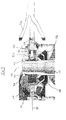
FIG. 2 is a cross-sectional view of an embodiment of a rotor assembly; -
FIG. 3 is a cross-sectional view of an embodiment of a tilted rotor assembly; -
FIG. 4 is a perspective view of an embodiment of a rotor assembly; -
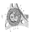
FIG. 5 is another cross-sectional view of an embodiment of a rotor assembly; -
FIG. 6 is an exploded view of an embodiment of a rotor assembly; and -
FIG. 7 is a perspective view of a bearing for a rotor assembly. - The detailed description explains embodiments of the invention, together with advantages and features, by way of example with reference to the drawings.
- Shown in
FIG. 1 is schematic view of an embodiment of rotorcraft, in this embodiment ahelicopter 10. Thehelicopter 10 includes anairframe 12 with an extendingtail 14 and a tail rotor 16 located thereat. While the embodiment of ahelicopter 10 described herein includes an extendingtail 14 and tail rotor 16, it is to be appreciated that the disclosure herein may be applied to other types of rotor craft, such as tilt wing or tilt rotor vertical takeoff and landing (VTOL) aircraft. Amain rotor assembly 18 is located at theairframe 12 and is driven by a rotor shaft 22 rotating about a rotor axis 20. The rotor shaft 22 is connected to a power source, for example, anengine 24 by agearbox 26. - Referring to
FIG. 2 , themain rotor assembly 18 rotates in a rotation plane 28 nominally perpendicular to the rotor axis 20. Themain rotor assembly 18 includes a gimbal bearing 30 allowing for tilt of the rotation plane 28 as desired relative to the rotor axis 20, as shown inFIG. 3 , so that the rotation plane 28 is no longer perpendicular to the rotor axis 20. To drive rotation of therotor assembly 18 while accommodating the tilt of the rotation plane 28, therotor assembly 18 is connected to the rotor shaft 22 by aconstant velocity drive 32. - Referring again to
FIG. 2 , therotor assembly 18 includes arotor hub 34 with a plurality ofrotor blades 36 extending radially outwardly from therotor hub 34. The gimbal bearing 30 and theconstant velocity drive 32 are secured to therotor hub 34 to allow for tilt thereof. The gimbal bearing 30 is further secured to the rotor shaft 22, although it is understood that the gimbal bearing 30 could also be attached to thedrive ring 38. The constant velocity drive 32 (hereinafter referred to as "drive 32") includes adrive ring 38 connected to the rotor shaft 22 via adrive spline 40 or other suitable connection and retained axially by aretaining ring 42. Thedrive 32 further includes a drivenring 44 fixed to therotor hub 34 and three or more drive links 46 extending between thedrive ring 38 and the drivenring 44. - As shown in
FIG. 4 , each drive link 46 is secured to thedrive ring 38 at aclevis 48 of thedrive ring 38, with apin 50 extending through theclevis 48 allowing for rotation of the drive link 46 about apin axis 52. Torque is transmitted from the rotor shaft 22 to thedrive ring 38 via thedrive spline 40, and from thedrive ring 38 to the drive links 46 via theclevis 48. As shown, theclevis 48 has two prongs extending from thering 38 through which thepin 50 extends to rotatably couple thedrive ring 38 and the drive link 46. However, it is understood that other attachment mechanisms can be used, such as where theclevis 48 has fewer or more prongs than what is shown in the exemplary embodiment. - Referring now to
FIG. 5 , each drive link 46 extends to the drivenring 44 and is supported at the drivenring 44 by anelastomeric bearing 54, through which torque is transmitted from the drive links 46 to the drivenring 44. Theelastomeric bearing 54, shown also in the partially exploded view ofFIG. 6 , includes aninner race 56 forming the interface with the drive link 46, and anouter race 58 to interface with the drivenring 44. In some embodiments, theouter race 58 is square or rectangular and fits into a bearing opening 60 in the drivenring 44, although the particular shape is not so limited according to the shape of theopening 60. - Referring now to
FIG. 7 , theelastomeric bearing 54 includes both spherical elements 62 and flat plate elements 64. In some embodiments, the spherical elements 62 and the flat plate elements, or planar elements 64 are separated by an intermediate race 66, with the spherical elements 62 positioned between theinner race 56 and the intermediate race 66 and the planar elements 64 positioned between the intermediate race 66 and the outer race 68. The spherical elements 62 accommodate the tilt of therotor assembly 18, while the planar elements 64 allow for the foreshortening on a distance between the drivenring 44 and thedrive ring 42 due to the tilt. - Additionally, as the
rotor hub 34 is tilted, a center-to-center distance between the spherical portions of theelastomeric bearings 54 varies as therotor hub 34 and rotor shaft 22 rotate about their respective axes. This expansion and contraction of the center-to-center distance results in a forced tangential deflection of eachelastomeric bearing 54. As eachelastomeric bearing 54 has the same spring rate, the tangential deflection is equally shared by the threeelastomeric bearings 54. This equalization of deflections ensures a constant velocity joint between therotor hub 34 and the rotor shaft 22. - While the invention has been described in detail in connection with only a limited number of embodiments, it should be readily understood that the invention is not limited to such disclosed embodiments. For instance, while described in terms of aircraft, it is understood that aspects could be used in other contexts such as for wind turbines, maritime propulsion, or other technologies in which a rotating element's plan of rotation will vary from perpendicular with the axis of rotation of a shaft driving the rotating element. Rather, the invention can be modified to incorporate any number of variations, alterations, substitutions or equivalent arrangements not heretofore described, but which are commensurate with the spirit and scope of the invention. Additionally, while various embodiments of the invention have been described, it is to be understood that aspects of the invention may include only some of the described embodiments. Accordingly, the invention is not to be seen as limited by the foregoing description, but is only limited by the scope of the appended claims.
- This invention was made with Government support under Agreement No. W911 W6-11-2-0007 for the Joint Multi-Role Demonstrator Configuration Trades and Analysis. The Government has certain rights in the invention
Claims (8)
- A constant velocity drive (32) comprising;
a drive ring (38) having a drive ring axis of rotation;
a driven ring (44) disposed around the drive ring (38) and which is driven by the drive ring (38) to rotate about a driven ring axis of rotation;
a plurality of drive links (46) extending from the drive ring (38) to the driven ring (44) to transfer torque applied at the drive ring (38) to the driven ring (44); and
a plurality of elastomeric bearings (54), each elastomeric bearing (54) disposed at the driven ring (44) to transfer torque from one of the plurality of drive links (46) to the driven ring (44), each elastomeric bearing (54) including both spherical bearing elements (62) and planar bearing elements (64) to allow for tilt of the driven ring axis of rotation with respect to the drive ring axis of rotation while ensuring a constant rotational velocity of the driven ring (44) with respect to the rotational velocity of the drive ring (38). - The constant velocity drive (32) of Claim 1, wherein each elastomeric bearing (54) includes an intermediate race (66) separating the spherical bearing elements (62) from the planar bearing elements (64).
- The constant velocity drive (32) of Claim 2, wherein each elastomeric bearing (54) includes an inner bearing race (56) interfacing with the respective drive link of the plurality of drive links (46), the spherical bearing elements (62) disposed between the inner bearing race (56) and the intermediate race (66).
- The constant velocity drive (32) of Claim 2 or 3, wherein each elastomeric bearing (54) includes an outer bearing race (58) interfacing with the driven ring (44), the planar bearing elements (64) disposed between the outer bearing race (58) and the intermediate race (66).
- The constant velocity drive (32) of any of Claims 1 to 4, further comprising a gimbal bearing (30) connected to the driven ring (44) and which reacts the tilt of the driven ring (44) relative to the drive ring (38).
- A rotor assembly (18) comprising:a rotor hub (34);a plurality of rotor blades (36) extending radially outwardly from the rotor hub (34);a constant velocity drive (32) according to any of the previous claims operably connecting the rotor hub (34) to a rotor shaft (22).
- The rotor assembly (18) of Claim 6, wherein the driven ring (44) is secured to the rotor hub (34), interposed between the rotor hub (34) and the drive ring (38), and driven by the drive ring (38) to rotate about a driven ring axis of rotation, the plurality of elastomeric bearings (54) disposed at the driven ring (44).
- A rotorcraft (10) comprising:an airframe (12);a drive system (24, 26) disposed at the airframe (12), the drive system including a drive shaft (22) rotating about a shaft axis (20); anda rotor assembly (18) according to claim 6 or 7 operably connected to the drive system.
Applications Claiming Priority (1)
| Application Number | Priority Date | Filing Date | Title |
|---|---|---|---|
| US14/153,482 US9452830B2 (en) | 2014-01-13 | 2014-01-13 | Constant velocity drive for tilt rotor assembly |
Publications (2)
| Publication Number | Publication Date |
|---|---|
| EP2894095A1 true EP2894095A1 (en) | 2015-07-15 |
| EP2894095B1 EP2894095B1 (en) | 2018-10-03 |
Family
ID=52003559
Family Applications (1)
| Application Number | Title | Priority Date | Filing Date |
|---|---|---|---|
| EP14192827.5A Not-in-force EP2894095B1 (en) | 2014-01-13 | 2014-11-12 | Constant velocity drive for tilt rotor assembly |
Country Status (2)
| Country | Link |
|---|---|
| US (1) | US9452830B2 (en) |
| EP (1) | EP2894095B1 (en) |
Families Citing this family (4)
| Publication number | Priority date | Publication date | Assignee | Title |
|---|---|---|---|---|
| WO2016118980A2 (en) * | 2015-01-21 | 2016-07-28 | Groenewald Felix Errol | Aircraft |
| US20180290740A1 (en) * | 2015-05-20 | 2018-10-11 | Sikorsky Aircraft Corporation | Mono-cyclic swashplate |
| US10442532B2 (en) * | 2016-11-18 | 2019-10-15 | Sikorsky Aircraft Corporation | Composite swashplate guide for rotorcraft control systems |
| JP7185498B2 (en) * | 2018-11-12 | 2022-12-07 | 株式会社Subaru | Rotorcraft and method of controlling rotorcraft |
Citations (4)
| Publication number | Priority date | Publication date | Assignee | Title |
|---|---|---|---|---|
| GB2141208A (en) * | 1983-06-08 | 1984-12-12 | Wright Barry Corp | Coupling |
| US20030178528A1 (en) * | 2002-03-20 | 2003-09-25 | Elio Zoppitelli | Rotary-wing aircraft rotor with constant velocity drive |
| WO2008020848A2 (en) * | 2006-08-17 | 2008-02-21 | Bell Helicopter Textron Inc. | Rotary-wing aircraft torque coupling with pad bearings |
| WO2010128378A2 (en) * | 2009-05-06 | 2010-11-11 | K4A S.R.L. | Constant velocity joint for helicopter rotors |
Family Cites Families (17)
| Publication number | Priority date | Publication date | Assignee | Title |
|---|---|---|---|---|
| US3804552A (en) | 1972-07-05 | 1974-04-16 | Textron Inc | Four blade main rotor control power coupling |
| US3841586A (en) | 1973-04-26 | 1974-10-15 | Boeing Co | Rotor swashplate assembly |
| US4087203A (en) * | 1977-01-07 | 1978-05-02 | United Technologies Corporation | Cross beam rotor |
| US4251187A (en) * | 1978-05-25 | 1981-02-17 | Kaman Aerospace Corporation | Blade retention bearing for helicopter rotor |
| US4695227A (en) | 1985-02-27 | 1987-09-22 | Hughes Helicopters Inc. | All composite, constant speed universal joint for use in a shaft driven tiltable main rotor for a helicopter |
| GB9006668D0 (en) | 1990-03-24 | 1990-05-23 | Westland Helicopters | Rotors |
| IT1240176B (en) * | 1990-04-06 | 1993-11-27 | Agusta Spa | MAIN ROTOR FOR HELICOPTERS |
| US5092738A (en) * | 1990-04-06 | 1992-03-03 | United Technologies Corporation | Flexbeam helicopter rotor with improved snubber-vibration damper between the torque tube and the flexible spar member |
| US5083725A (en) | 1990-10-11 | 1992-01-28 | United Technologies Corporation | Elastomeric swashplate configuration for helicopters |
| US5188513A (en) * | 1990-12-17 | 1993-02-23 | United Technologies Corporation | Snubber-bearing with combined elastomer laminates |
| US5913659A (en) * | 1993-11-22 | 1999-06-22 | United Technologies Corporation | Apparatus and method for adjusting rotor blade tracking |
| US5499903A (en) * | 1994-10-18 | 1996-03-19 | United Technologies Corporation | Snubber bearing mounting assembly for bearingless rotors |
| US5460487A (en) * | 1994-11-09 | 1995-10-24 | United Technologies Corporation | Pitch adjustment assembly for bearingless main rotors |
| FR2837784B1 (en) | 2002-03-28 | 2004-05-28 | Eurocopter France | CELLULAR DRIVE ROTOR ROTOR WITH TORQUE SHARING DIFFERENTIAL |
| DE06750638T1 (en) * | 2005-11-30 | 2009-02-26 | Bell Helicopter Textron, Inc., Fort Worth | TORQUE CLUTCH FOR A TURN FLOATER |
| EP2240366B1 (en) * | 2008-02-12 | 2014-06-18 | Bell Helicopter Textron Inc. | Lead-lag damper for rotor hubs |
| EP2686239B1 (en) * | 2011-06-29 | 2015-08-12 | Bell Helicopter Textron Inc. | Rotor hub for use with high-inertia blades |
-
2014
- 2014-01-13 US US14/153,482 patent/US9452830B2/en not_active Expired - Fee Related
- 2014-11-12 EP EP14192827.5A patent/EP2894095B1/en not_active Not-in-force
Patent Citations (4)
| Publication number | Priority date | Publication date | Assignee | Title |
|---|---|---|---|---|
| GB2141208A (en) * | 1983-06-08 | 1984-12-12 | Wright Barry Corp | Coupling |
| US20030178528A1 (en) * | 2002-03-20 | 2003-09-25 | Elio Zoppitelli | Rotary-wing aircraft rotor with constant velocity drive |
| WO2008020848A2 (en) * | 2006-08-17 | 2008-02-21 | Bell Helicopter Textron Inc. | Rotary-wing aircraft torque coupling with pad bearings |
| WO2010128378A2 (en) * | 2009-05-06 | 2010-11-11 | K4A S.R.L. | Constant velocity joint for helicopter rotors |
Also Published As
| Publication number | Publication date |
|---|---|
| US20150197332A1 (en) | 2015-07-16 |
| EP2894095B1 (en) | 2018-10-03 |
| US9452830B2 (en) | 2016-09-27 |
Similar Documents
| Publication | Publication Date | Title |
|---|---|---|
| US10384771B2 (en) | Gimbaled tail rotor hub with spherical elastomeric centrifugal force bearing for blade retention and pitch change articulation | |
| EP2238027B1 (en) | Constant-velocity joint with torque-combining differential | |
| US9039373B2 (en) | Blade-pitch control system with feedback lever | |
| CA2805167C (en) | Aircraft rotor with discrete flap hinge | |
| US9382001B2 (en) | Torque transfer system for a rotorcraft | |
| US20150053814A1 (en) | Rotor System with Torque-Splitter Assembly | |
| US20180029700A1 (en) | Anti-Drive Mechanism for Rise and Fall Rotating Control Systems | |
| EP2894095B1 (en) | Constant velocity drive for tilt rotor assembly | |
| US9657816B2 (en) | Drive link for tiltrotor rotor system | |
| US11136116B2 (en) | Elastomeric double Hooke's joint | |
| US20150345551A1 (en) | Rotorcraft bearing with rotation slip joint | |
| JP4112870B2 (en) | Aircraft constant speed transmission rotor | |
| US20180327086A1 (en) | Gimbaled Rotor Hub Assembly with Spherical Bearing | |
| US10696386B2 (en) | Rigid rotor head with tension torsion (TT) strap retention | |
| EP3434588B1 (en) | Rotor hub assembly with universal joint | |
| CN118323438A (en) | Universal hinged propeller hub of tiltrotor aircraft, and tiltrotor aircraft | |
| US11732747B2 (en) | Journal bearings | |
| CN116981620A (en) | aircraft capable of hovering | |
| US10358212B2 (en) | Aircraft rotor assembly with composite laminate | |
| US20190276143A1 (en) | Blade retention system for rigid rotor |
Legal Events
| Date | Code | Title | Description |
|---|---|---|---|
| PUAI | Public reference made under article 153(3) epc to a published international application that has entered the european phase |
Free format text: ORIGINAL CODE: 0009012 |
|
| 17P | Request for examination filed |
Effective date: 20141112 |
|
| AK | Designated contracting states |
Kind code of ref document: A1 Designated state(s): AL AT BE BG CH CY CZ DE DK EE ES FI FR GB GR HR HU IE IS IT LI LT LU LV MC MK MT NL NO PL PT RO RS SE SI SK SM TR |
|
| AX | Request for extension of the european patent |
Extension state: BA ME |
|
| R17P | Request for examination filed (corrected) |
Effective date: 20151216 |
|
| RBV | Designated contracting states (corrected) |
Designated state(s): AL AT BE BG CH CY CZ DE DK EE ES FI FR GB GR HR HU IE IS IT LI LT LU LV MC MK MT NL NO PL PT RO RS SE SI SK SM TR |
|
| GRAP | Despatch of communication of intention to grant a patent |
Free format text: ORIGINAL CODE: EPIDOSNIGR1 |
|
| INTG | Intention to grant announced |
Effective date: 20180423 |
|
| GRAS | Grant fee paid |
Free format text: ORIGINAL CODE: EPIDOSNIGR3 |
|
| GRAA | (expected) grant |
Free format text: ORIGINAL CODE: 0009210 |
|
| AK | Designated contracting states |
Kind code of ref document: B1 Designated state(s): AL AT BE BG CH CY CZ DE DK EE ES FI FR GB GR HR HU IE IS IT LI LT LU LV MC MK MT NL NO PL PT RO RS SE SI SK SM TR |
|
| REG | Reference to a national code |
Ref country code: GB Ref legal event code: FG4D |
|
| REG | Reference to a national code |
Ref country code: CH Ref legal event code: EP Ref country code: AT Ref legal event code: REF Ref document number: 1048317 Country of ref document: AT Kind code of ref document: T Effective date: 20181015 |
|
| REG | Reference to a national code |
Ref country code: IE Ref legal event code: FG4D Ref country code: DE Ref legal event code: R096 Ref document number: 602014033284 Country of ref document: DE |
|
| PGFP | Annual fee paid to national office [announced via postgrant information from national office to epo] |
Ref country code: DE Payment date: 20181128 Year of fee payment: 5 |
|
| REG | Reference to a national code |
Ref country code: NL Ref legal event code: MP Effective date: 20181003 |
|
| REG | Reference to a national code |
Ref country code: LT Ref legal event code: MG4D |
|
| PGFP | Annual fee paid to national office [announced via postgrant information from national office to epo] |
Ref country code: GB Payment date: 20181127 Year of fee payment: 5 Ref country code: FR Payment date: 20181127 Year of fee payment: 5 |
|
| REG | Reference to a national code |
Ref country code: AT Ref legal event code: MK05 Ref document number: 1048317 Country of ref document: AT Kind code of ref document: T Effective date: 20181003 |
|
| PG25 | Lapsed in a contracting state [announced via postgrant information from national office to epo] |
Ref country code: NL Free format text: LAPSE BECAUSE OF FAILURE TO SUBMIT A TRANSLATION OF THE DESCRIPTION OR TO PAY THE FEE WITHIN THE PRESCRIBED TIME-LIMIT Effective date: 20181003 |
|
| PG25 | Lapsed in a contracting state [announced via postgrant information from national office to epo] |
Ref country code: BG Free format text: LAPSE BECAUSE OF FAILURE TO SUBMIT A TRANSLATION OF THE DESCRIPTION OR TO PAY THE FEE WITHIN THE PRESCRIBED TIME-LIMIT Effective date: 20190103 Ref country code: PL Free format text: LAPSE BECAUSE OF FAILURE TO SUBMIT A TRANSLATION OF THE DESCRIPTION OR TO PAY THE FEE WITHIN THE PRESCRIBED TIME-LIMIT Effective date: 20181003 Ref country code: IS Free format text: LAPSE BECAUSE OF FAILURE TO SUBMIT A TRANSLATION OF THE DESCRIPTION OR TO PAY THE FEE WITHIN THE PRESCRIBED TIME-LIMIT Effective date: 20190203 Ref country code: HR Free format text: LAPSE BECAUSE OF FAILURE TO SUBMIT A TRANSLATION OF THE DESCRIPTION OR TO PAY THE FEE WITHIN THE PRESCRIBED TIME-LIMIT Effective date: 20181003 Ref country code: NO Free format text: LAPSE BECAUSE OF FAILURE TO SUBMIT A TRANSLATION OF THE DESCRIPTION OR TO PAY THE FEE WITHIN THE PRESCRIBED TIME-LIMIT Effective date: 20190103 Ref country code: CZ Free format text: LAPSE BECAUSE OF FAILURE TO SUBMIT A TRANSLATION OF THE DESCRIPTION OR TO PAY THE FEE WITHIN THE PRESCRIBED TIME-LIMIT Effective date: 20181003 Ref country code: LT Free format text: LAPSE BECAUSE OF FAILURE TO SUBMIT A TRANSLATION OF THE DESCRIPTION OR TO PAY THE FEE WITHIN THE PRESCRIBED TIME-LIMIT Effective date: 20181003 Ref country code: ES Free format text: LAPSE BECAUSE OF FAILURE TO SUBMIT A TRANSLATION OF THE DESCRIPTION OR TO PAY THE FEE WITHIN THE PRESCRIBED TIME-LIMIT Effective date: 20181003 Ref country code: AT Free format text: LAPSE BECAUSE OF FAILURE TO SUBMIT A TRANSLATION OF THE DESCRIPTION OR TO PAY THE FEE WITHIN THE PRESCRIBED TIME-LIMIT Effective date: 20181003 Ref country code: LV Free format text: LAPSE BECAUSE OF FAILURE TO SUBMIT A TRANSLATION OF THE DESCRIPTION OR TO PAY THE FEE WITHIN THE PRESCRIBED TIME-LIMIT Effective date: 20181003 Ref country code: FI Free format text: LAPSE BECAUSE OF FAILURE TO SUBMIT A TRANSLATION OF THE DESCRIPTION OR TO PAY THE FEE WITHIN THE PRESCRIBED TIME-LIMIT Effective date: 20181003 |
|
| PG25 | Lapsed in a contracting state [announced via postgrant information from national office to epo] |
Ref country code: AL Free format text: LAPSE BECAUSE OF FAILURE TO SUBMIT A TRANSLATION OF THE DESCRIPTION OR TO PAY THE FEE WITHIN THE PRESCRIBED TIME-LIMIT Effective date: 20181003 Ref country code: RS Free format text: LAPSE BECAUSE OF FAILURE TO SUBMIT A TRANSLATION OF THE DESCRIPTION OR TO PAY THE FEE WITHIN THE PRESCRIBED TIME-LIMIT Effective date: 20181003 Ref country code: SE Free format text: LAPSE BECAUSE OF FAILURE TO SUBMIT A TRANSLATION OF THE DESCRIPTION OR TO PAY THE FEE WITHIN THE PRESCRIBED TIME-LIMIT Effective date: 20181003 Ref country code: GR Free format text: LAPSE BECAUSE OF FAILURE TO SUBMIT A TRANSLATION OF THE DESCRIPTION OR TO PAY THE FEE WITHIN THE PRESCRIBED TIME-LIMIT Effective date: 20190104 Ref country code: PT Free format text: LAPSE BECAUSE OF FAILURE TO SUBMIT A TRANSLATION OF THE DESCRIPTION OR TO PAY THE FEE WITHIN THE PRESCRIBED TIME-LIMIT Effective date: 20190203 |
|
| REG | Reference to a national code |
Ref country code: CH Ref legal event code: PL |
|
| REG | Reference to a national code |
Ref country code: DE Ref legal event code: R097 Ref document number: 602014033284 Country of ref document: DE |
|
| PG25 | Lapsed in a contracting state [announced via postgrant information from national office to epo] |
Ref country code: DK Free format text: LAPSE BECAUSE OF FAILURE TO SUBMIT A TRANSLATION OF THE DESCRIPTION OR TO PAY THE FEE WITHIN THE PRESCRIBED TIME-LIMIT Effective date: 20181003 Ref country code: IT Free format text: LAPSE BECAUSE OF FAILURE TO SUBMIT A TRANSLATION OF THE DESCRIPTION OR TO PAY THE FEE WITHIN THE PRESCRIBED TIME-LIMIT Effective date: 20181003 Ref country code: LU Free format text: LAPSE BECAUSE OF NON-PAYMENT OF DUE FEES Effective date: 20181112 |
|
| PLBE | No opposition filed within time limit |
Free format text: ORIGINAL CODE: 0009261 |
|
| STAA | Information on the status of an ep patent application or granted ep patent |
Free format text: STATUS: NO OPPOSITION FILED WITHIN TIME LIMIT |
|
| REG | Reference to a national code |
Ref country code: BE Ref legal event code: MM Effective date: 20181130 |
|
| REG | Reference to a national code |
Ref country code: IE Ref legal event code: MM4A |
|
| PG25 | Lapsed in a contracting state [announced via postgrant information from national office to epo] |
Ref country code: MC Free format text: LAPSE BECAUSE OF FAILURE TO SUBMIT A TRANSLATION OF THE DESCRIPTION OR TO PAY THE FEE WITHIN THE PRESCRIBED TIME-LIMIT Effective date: 20181003 Ref country code: RO Free format text: LAPSE BECAUSE OF FAILURE TO SUBMIT A TRANSLATION OF THE DESCRIPTION OR TO PAY THE FEE WITHIN THE PRESCRIBED TIME-LIMIT Effective date: 20181003 Ref country code: SK Free format text: LAPSE BECAUSE OF FAILURE TO SUBMIT A TRANSLATION OF THE DESCRIPTION OR TO PAY THE FEE WITHIN THE PRESCRIBED TIME-LIMIT Effective date: 20181003 Ref country code: EE Free format text: LAPSE BECAUSE OF FAILURE TO SUBMIT A TRANSLATION OF THE DESCRIPTION OR TO PAY THE FEE WITHIN THE PRESCRIBED TIME-LIMIT Effective date: 20181003 Ref country code: SM Free format text: LAPSE BECAUSE OF FAILURE TO SUBMIT A TRANSLATION OF THE DESCRIPTION OR TO PAY THE FEE WITHIN THE PRESCRIBED TIME-LIMIT Effective date: 20181003 Ref country code: CH Free format text: LAPSE BECAUSE OF NON-PAYMENT OF DUE FEES Effective date: 20181130 Ref country code: LI Free format text: LAPSE BECAUSE OF NON-PAYMENT OF DUE FEES Effective date: 20181130 |
|
| 26N | No opposition filed |
Effective date: 20190704 |
|
| PG25 | Lapsed in a contracting state [announced via postgrant information from national office to epo] |
Ref country code: IE Free format text: LAPSE BECAUSE OF NON-PAYMENT OF DUE FEES Effective date: 20181112 Ref country code: SI Free format text: LAPSE BECAUSE OF FAILURE TO SUBMIT A TRANSLATION OF THE DESCRIPTION OR TO PAY THE FEE WITHIN THE PRESCRIBED TIME-LIMIT Effective date: 20181003 |
|
| PG25 | Lapsed in a contracting state [announced via postgrant information from national office to epo] |
Ref country code: BE Free format text: LAPSE BECAUSE OF NON-PAYMENT OF DUE FEES Effective date: 20181130 |
|
| PG25 | Lapsed in a contracting state [announced via postgrant information from national office to epo] |
Ref country code: MT Free format text: LAPSE BECAUSE OF NON-PAYMENT OF DUE FEES Effective date: 20181112 |
|
| PG25 | Lapsed in a contracting state [announced via postgrant information from national office to epo] |
Ref country code: TR Free format text: LAPSE BECAUSE OF FAILURE TO SUBMIT A TRANSLATION OF THE DESCRIPTION OR TO PAY THE FEE WITHIN THE PRESCRIBED TIME-LIMIT Effective date: 20181003 |
|
| REG | Reference to a national code |
Ref country code: DE Ref legal event code: R119 Ref document number: 602014033284 Country of ref document: DE |
|
| PG25 | Lapsed in a contracting state [announced via postgrant information from national office to epo] |
Ref country code: CY Free format text: LAPSE BECAUSE OF FAILURE TO SUBMIT A TRANSLATION OF THE DESCRIPTION OR TO PAY THE FEE WITHIN THE PRESCRIBED TIME-LIMIT Effective date: 20181003 Ref country code: MK Free format text: LAPSE BECAUSE OF NON-PAYMENT OF DUE FEES Effective date: 20181003 Ref country code: HU Free format text: LAPSE BECAUSE OF FAILURE TO SUBMIT A TRANSLATION OF THE DESCRIPTION OR TO PAY THE FEE WITHIN THE PRESCRIBED TIME-LIMIT; INVALID AB INITIO Effective date: 20141112 |
|
| GBPC | Gb: european patent ceased through non-payment of renewal fee |
Effective date: 20191112 |
|
| PG25 | Lapsed in a contracting state [announced via postgrant information from national office to epo] |
Ref country code: DE Free format text: LAPSE BECAUSE OF NON-PAYMENT OF DUE FEES Effective date: 20200603 Ref country code: FR Free format text: LAPSE BECAUSE OF NON-PAYMENT OF DUE FEES Effective date: 20191130 Ref country code: GB Free format text: LAPSE BECAUSE OF NON-PAYMENT OF DUE FEES Effective date: 20191112 |