EP2893999B1 - A device for adjusting cutting depth for removal of weld beads inside profile sections such as tubes and the like. - Google Patents
A device for adjusting cutting depth for removal of weld beads inside profile sections such as tubes and the like. Download PDFInfo
- Publication number
- EP2893999B1 EP2893999B1 EP14196036.9A EP14196036A EP2893999B1 EP 2893999 B1 EP2893999 B1 EP 2893999B1 EP 14196036 A EP14196036 A EP 14196036A EP 2893999 B1 EP2893999 B1 EP 2893999B1
- Authority
- EP
- European Patent Office
- Prior art keywords
- rollers
- supporting frame
- cutting depth
- adjusting cutting
- control
- Prior art date
- Legal status (The legal status is an assumption and is not a legal conclusion. Google has not performed a legal analysis and makes no representation as to the accuracy of the status listed.)
- Active
Links
Images


Classifications
-
- B—PERFORMING OPERATIONS; TRANSPORTING
- B21—MECHANICAL METAL-WORKING WITHOUT ESSENTIALLY REMOVING MATERIAL; PUNCHING METAL
- B21C—MANUFACTURE OF METAL SHEETS, WIRE, RODS, TUBES, PROFILES OR LIKE SEMI-MANUFACTURED PRODUCTS OTHERWISE THAN BY ROLLING; AUXILIARY OPERATIONS USED IN CONNECTION WITH METAL-WORKING WITHOUT ESSENTIALLY REMOVING MATERIAL
- B21C37/00—Manufacture of metal sheets, rods, wire, tubes, profiles or like semi-manufactured products, not otherwise provided for; Manufacture of tubes of special shape
- B21C37/06—Manufacture of metal sheets, rods, wire, tubes, profiles or like semi-manufactured products, not otherwise provided for; Manufacture of tubes of special shape of tubes or metal hoses; Combined procedures for making tubes, e.g. for making multi-wall tubes
- B21C37/08—Making tubes with welded or soldered seams
- B21C37/0807—Tube treating or manipulating combined with, or specially adapted for use in connection with tube making machines, e.g. drawing-off devices, cutting-off
- B21C37/0811—Tube treating or manipulating combined with, or specially adapted for use in connection with tube making machines, e.g. drawing-off devices, cutting-off removing or treating the weld bead
-
- B—PERFORMING OPERATIONS; TRANSPORTING
- B23—MACHINE TOOLS; METAL-WORKING NOT OTHERWISE PROVIDED FOR
- B23D—PLANING; SLOTTING; SHEARING; BROACHING; SAWING; FILING; SCRAPING; LIKE OPERATIONS FOR WORKING METAL BY REMOVING MATERIAL, NOT OTHERWISE PROVIDED FOR
- B23D79/00—Methods, machines, or devices not covered elsewhere, for working metal by removal of material
- B23D79/02—Machines or devices for scraping
- B23D79/021—Machines or devices for scraping for removing welding, brazing or soldering burrs, e.g. flash, on pipes or rods
- B23D79/023—Machines or devices for scraping for removing welding, brazing or soldering burrs, e.g. flash, on pipes or rods internally
-
- B—PERFORMING OPERATIONS; TRANSPORTING
- B23—MACHINE TOOLS; METAL-WORKING NOT OTHERWISE PROVIDED FOR
- B23D—PLANING; SLOTTING; SHEARING; BROACHING; SAWING; FILING; SCRAPING; LIKE OPERATIONS FOR WORKING METAL BY REMOVING MATERIAL, NOT OTHERWISE PROVIDED FOR
- B23D1/00—Planing or slotting machines cutting by relative movement of the tool and workpiece in a horizontal straight line only
- B23D1/003—Planing or slotting machines cutting by relative movement of the tool and workpiece in a horizontal straight line only for planing elongated workpieces
-
- B—PERFORMING OPERATIONS; TRANSPORTING
- B23—MACHINE TOOLS; METAL-WORKING NOT OTHERWISE PROVIDED FOR
- B23D—PLANING; SLOTTING; SHEARING; BROACHING; SAWING; FILING; SCRAPING; LIKE OPERATIONS FOR WORKING METAL BY REMOVING MATERIAL, NOT OTHERWISE PROVIDED FOR
- B23D1/00—Planing or slotting machines cutting by relative movement of the tool and workpiece in a horizontal straight line only
- B23D1/08—Planing or slotting machines cutting by relative movement of the tool and workpiece in a horizontal straight line only by movement of the tool
-
- B—PERFORMING OPERATIONS; TRANSPORTING
- B23—MACHINE TOOLS; METAL-WORKING NOT OTHERWISE PROVIDED FOR
- B23D—PLANING; SLOTTING; SHEARING; BROACHING; SAWING; FILING; SCRAPING; LIKE OPERATIONS FOR WORKING METAL BY REMOVING MATERIAL, NOT OTHERWISE PROVIDED FOR
- B23D1/00—Planing or slotting machines cutting by relative movement of the tool and workpiece in a horizontal straight line only
- B23D1/08—Planing or slotting machines cutting by relative movement of the tool and workpiece in a horizontal straight line only by movement of the tool
- B23D1/10—Planing or slotting machines cutting by relative movement of the tool and workpiece in a horizontal straight line only by movement of the tool with means for adjusting the tool-guide vertically
-
- B—PERFORMING OPERATIONS; TRANSPORTING
- B23—MACHINE TOOLS; METAL-WORKING NOT OTHERWISE PROVIDED FOR
- B23D—PLANING; SLOTTING; SHEARING; BROACHING; SAWING; FILING; SCRAPING; LIKE OPERATIONS FOR WORKING METAL BY REMOVING MATERIAL, NOT OTHERWISE PROVIDED FOR
- B23D1/00—Planing or slotting machines cutting by relative movement of the tool and workpiece in a horizontal straight line only
- B23D1/20—Planing or slotting machines cutting by relative movement of the tool and workpiece in a horizontal straight line only with tool-supports or work-supports specially mounted or guided for working in different directions or at different angles; Special purpose machines
- B23D1/24—Planing or slotting machines cutting by relative movement of the tool and workpiece in a horizontal straight line only with tool-supports or work-supports specially mounted or guided for working in different directions or at different angles; Special purpose machines for planing inner surfaces, e.g. of moulds
-
- B—PERFORMING OPERATIONS; TRANSPORTING
- B23—MACHINE TOOLS; METAL-WORKING NOT OTHERWISE PROVIDED FOR
- B23D—PLANING; SLOTTING; SHEARING; BROACHING; SAWING; FILING; SCRAPING; LIKE OPERATIONS FOR WORKING METAL BY REMOVING MATERIAL, NOT OTHERWISE PROVIDED FOR
- B23D1/00—Planing or slotting machines cutting by relative movement of the tool and workpiece in a horizontal straight line only
- B23D1/20—Planing or slotting machines cutting by relative movement of the tool and workpiece in a horizontal straight line only with tool-supports or work-supports specially mounted or guided for working in different directions or at different angles; Special purpose machines
- B23D1/26—Planing or slotting machines cutting by relative movement of the tool and workpiece in a horizontal straight line only with tool-supports or work-supports specially mounted or guided for working in different directions or at different angles; Special purpose machines for planing edges or ridges or cutting grooves
-
- B—PERFORMING OPERATIONS; TRANSPORTING
- B23—MACHINE TOOLS; METAL-WORKING NOT OTHERWISE PROVIDED FOR
- B23D—PLANING; SLOTTING; SHEARING; BROACHING; SAWING; FILING; SCRAPING; LIKE OPERATIONS FOR WORKING METAL BY REMOVING MATERIAL, NOT OTHERWISE PROVIDED FOR
- B23D79/00—Methods, machines, or devices not covered elsewhere, for working metal by removal of material
- B23D79/02—Machines or devices for scraping
- B23D79/021—Machines or devices for scraping for removing welding, brazing or soldering burrs, e.g. flash, on pipes or rods
-
- B—PERFORMING OPERATIONS; TRANSPORTING
- B26—HAND CUTTING TOOLS; CUTTING; SEVERING
- B26D—CUTTING; DETAILS COMMON TO MACHINES FOR PERFORATING, PUNCHING, CUTTING-OUT, STAMPING-OUT OR SEVERING
- B26D3/00—Cutting work characterised by the nature of the cut made; Apparatus therefor
- B26D3/001—Cutting tubes longitudinally
-
- Y—GENERAL TAGGING OF NEW TECHNOLOGICAL DEVELOPMENTS; GENERAL TAGGING OF CROSS-SECTIONAL TECHNOLOGIES SPANNING OVER SEVERAL SECTIONS OF THE IPC; TECHNICAL SUBJECTS COVERED BY FORMER USPC CROSS-REFERENCE ART COLLECTIONS [XRACs] AND DIGESTS
- Y10—TECHNICAL SUBJECTS COVERED BY FORMER USPC
- Y10T—TECHNICAL SUBJECTS COVERED BY FORMER US CLASSIFICATION
- Y10T409/00—Gear cutting, milling, or planing
- Y10T409/50—Planing
- Y10T409/501476—Means to remove flash or burr
-
- Y—GENERAL TAGGING OF NEW TECHNOLOGICAL DEVELOPMENTS; GENERAL TAGGING OF CROSS-SECTIONAL TECHNOLOGIES SPANNING OVER SEVERAL SECTIONS OF THE IPC; TECHNICAL SUBJECTS COVERED BY FORMER USPC CROSS-REFERENCE ART COLLECTIONS [XRACs] AND DIGESTS
- Y10—TECHNICAL SUBJECTS COVERED BY FORMER USPC
- Y10T—TECHNICAL SUBJECTS COVERED BY FORMER US CLASSIFICATION
- Y10T409/00—Gear cutting, milling, or planing
- Y10T409/50—Planing
- Y10T409/501476—Means to remove flash or burr
- Y10T409/50164—Elongated work
-
- Y—GENERAL TAGGING OF NEW TECHNOLOGICAL DEVELOPMENTS; GENERAL TAGGING OF CROSS-SECTIONAL TECHNOLOGIES SPANNING OVER SEVERAL SECTIONS OF THE IPC; TECHNICAL SUBJECTS COVERED BY FORMER USPC CROSS-REFERENCE ART COLLECTIONS [XRACs] AND DIGESTS
- Y10—TECHNICAL SUBJECTS COVERED BY FORMER USPC
- Y10T—TECHNICAL SUBJECTS COVERED BY FORMER US CLASSIFICATION
- Y10T409/00—Gear cutting, milling, or planing
- Y10T409/50—Planing
- Y10T409/501476—Means to remove flash or burr
- Y10T409/50164—Elongated work
- Y10T409/501804—Flash or burr inside hollow work
Definitions
- the present invention relates to a device according to the preamble of claim 1 for adjusting a cutting depth for removal of weld beads inside profile sections.
- the invention is applicable for removing weld beads, usually known as debeading, which beads are present internally of closed-section profile elements.
- the invention is useful for debeading internally of tubes obtained by welding.
- the weld beads are predisposed longitudinally internally of tubes obtained by welding.
- the closed profile is, for the purpose of information, completed by means of a continuous welding of the two flaps, reciprocally-facing following a forming operation realized by plastic deformation starting from a flat continuous strip.
- the welding gives rise to a weld bead on both the external side and the inner side of the profile section.
- the main drawback to be overcome relates to keeping under control the depth of the cut of the internal bead remover tool with the aim of ensuring a qualitative constancy in the carrying-out of the operation, between a replacement and another of the tool due to wear or for programmed maintenance.
- a further aim of the invention is to be able to command, from the outside, the adjustment using a device that is simple to manufacture and also simple to activate.
- a further aim is to provide a device that is structurally configured such as to operate without drawbacks and in safety in severe working conditions due to temperature, etc.
- 1 denotes in its entirety a supporting frame of a tool for removing an internal weld bead 4 of a closed-section profile element constituted in the example by a tube 2 obtained by welding.
- This tool is specifically structured for enabling adjustment of the cutting depth of a bead remover 26 usable for the removal of said weld bead 4 internally of the tube 2, which operation is commonly known as debeading.
- the supporting frame 1 has an elongated shape and exhibits, together with the parts associated thereto, transverse dimensions enabling it to be contained internally of the tube 2.
- the supporting frame 1 is associated, at an end 29 thereof, to an arm or rod, not illustrated in the accompanying figures, which projects from the open end of the tube 2 and is fixed externally thereof.
- a plurality of rolling elements 3 is constrained to the lower part of said supporting frame 1, which rolling elements 3 are located at a pre-established mutual distance in a longitudinal direction.
- the rolling elements 3 partially project from the body of the supporting frame 1 and are predisposed to come into contact with the internal surface of the tube 2 in a diametrically-opposite zone to a zone whereon the internal weld bead 4 lies.
- At least two idle rollers 5 are predisposed superiorly of the supporting frame 1, which rollers 5 are arranged longitudinally at a pre-established distance from one another and are mounted on small frames or levers 6 that are mobile in a transverse direction with respect to the longitudinal axis of the supporting frame 1 so as to be positionable in any position comprised from at least an active position, at which the rollers 5 are in contact with the inner surface of the tube 2 in proximity of the internal weld bead 4, to at least an inactive position, at which the rollers 5 are not in contact with the inner surface of the tube 2.
- the idle rollers 5 are arranged longitudinally, i.e. parallel to the longitudinal axis of the device, at a pre-established distance from one another on a same axial plane and exhibit an external rolling surface thereof profiled with a central groove 25 dimensioned so as to house the said internal weld bead 4 internally thereof.
- the wheels 5 are commanded to carry out the transverse displacements thereof by command of a command mechanism having inclined surfaces 7.
- Said command mechanism having inclined surfaces 7 is activated by a hydraulic linear actuator 8.
- the inclined surfaces 7 exhibit an identical inclination to the longitudinal axis of the supporting frame 1 and are solidly constrained on slides 9 which are longitudinally slidable with respect to the body of the supporting frame 1 and mechanically connected, by a stem 10, to the piston 11 of the hydraulic linear actuator 8 so that a longitudinal displacement of both the inclined surfaces 7 produces a transverse displacement of the rollers 5 in the same direction.
- rollers 5 are in fact rotatably mounted on small frames 6 or levers which at an end thereof are pivoted on posts 31 fixed to the supporting frame 1, while on the other end thereof they are predisposed to interact in contact with the respective inclined surfaces 7.
- an axial displacement of the inclined surfaces 7 produces a rotation by a same entity, but in an opposite direction, of the small frames 6 or levers which in turn generates identical transverse displacements of the wheels 5.
- the piston 11 divides the internal volume of the cylinder 27 of the hydraulic linear actuator 8 into two manoeuvring chambers 12 and 13 which are connected in a like manner by means of hydraulic conduits 22 and 23, only schematically represented in figure 1 , to two corresponding command chambers 32 and 33 of an external hydraulic command cylinder 14, which is part of an external control console 15 and is provided with a control piston 16.
- the control piston 16 is provided with at least a control rod 17 on an end of which, external of the hydraulic control cylinder 14, an operative adjustment knob 18 operates for enabling realization of the axial displacement in the two directions of the control rod 17 and the control piston 16 connected thereto with respect to the hydraulic control cylinder 14.
- the adjustment knob 18 is axially constrained and is coupled to the said end of the control rod 17 by means of a coupling comprising an operating screw 19.
- the two control chambers 32 and 33 of the hydraulic control cylinder 14 can be, as for example is represented in the illustrated embodiment, exactly corresponding in terms of dimensions and capacity to the two manoeuvring chambers 12 and 13 of the hydraulic linear actuator 8.
- the dimensions and capacities of the control chambers 32 and 33 are also different to the dimensions and capacities of the manoeuvring chambers 12 and 13. This enables realizing a greater or smaller control sensitivity.
- the control chambers 32 and 33 having smaller dimensions and capacities than those of the corresponding control chamber 12 and 13, in order to realize a determined displacement of the piston (11) it will be necessary to operate a greater displacement of the control piston 16. Therefore a finer adjustment of the axial displacement of the inclined surfaces 7 can be made, and therefore the rollers 5 can exploit a greater sensitivity of adjustment i.e. greater axial displacements of the control piston 16.
- An indicator 20 is solidly connected to the control rod 17 of the control piston 16, which indicator 20 operates on a fixed graduated scale 21 so as to indicate the displacements of the control piston 16 and consequently the axial displacements of the piston 11 commanding the transverse displacements of the rollers 5.
- the plurality of rolling elements 3 comprises two pairs of small idle rollers 30 mounted on a mobile frame 24; the small idle rollers 30 of each pair is flanked and arranged with relative axes that are not parallel to one another and lying on a transverse plane to the axis of the supporting frame 1.
- the mobile frame 24 is constrained to undergo guided displacements in a transverse direction with respect to the supporting frame 1 by action of contrast means 28.
- This enables the whole tool to rest with the idle rollers 30 on the internal surface of the tube 2 in a diametrically-opposite position to the position against which the rollers 5 go to operate, thus realizing an adequate contrast.
- the contrast means 28 can be hydraulically-activated, pneumatically-activated or even elastic, by means of springs.
- At least a bead remover tool 26 is solidly fixed to the supporting frame 1 on the same axial plane in which the rollers 5 are contained.
- the assembly constituted by the rolling elements 3, located in the lower part of the supporting frame 1, and the rollers 5 is located, in an axial direction, in an opposite position to the cutting edge of the bead remover tool 26 with respect to an ideal plane perpendicular to the longitudinal axis of the supporting frame 1 and tangential to said cutting edge.
- the rollers 5 are in a pre-established position.
- the contrast elements 28 are activated to work on the mobile frame 24, transversely distancing from the body of the device and operating the descent up to when the rolling elements 3 arrive in contact with the lower zone of the internal surface of the tube 2. In this way a sort of expansion occurs which proceeds up to when all the rolling elements 3 and the rollers 5 are solidly in contact with the respective zones of the internal surface of the tube 2.
- This displacement is determined proportionally to the displacement induced by the control piston 16.
- the adjusting of the cutting depth is in fact essentially determined by the radial distance with respect to the axis of the tube 2 which is realised between the cutting of the tool 26 and the rolling surfaces of the rollers 5.
- the small idle rollers 30 act in opposition, contributing to maintaining the centred position of the tool with respect to the tube element 2.
- the eventual insertion between the rod (not illustrated) and the supporting frame 1 of sensors able to measure the longitudinal component of the traction force or the variations in acceleration during the carrying-out of the debeading operations can enable obtaining a signalling of possible faults and thus correcting them by acting on the adjustment on the basis of the invention.
Landscapes
- Engineering & Computer Science (AREA)
- Mechanical Engineering (AREA)
- Physics & Mathematics (AREA)
- Optics & Photonics (AREA)
- Milling, Broaching, Filing, Reaming, And Others (AREA)
- Milling Processes (AREA)
- Grinding And Polishing Of Tertiary Curved Surfaces And Surfaces With Complex Shapes (AREA)
- Tyre Moulding (AREA)
- Finish Polishing, Edge Sharpening, And Grinding By Specific Grinding Devices (AREA)
- Processing And Handling Of Plastics And Other Materials For Molding In General (AREA)
Description
- The present invention relates to a device according to the preamble of claim 1 for adjusting a cutting depth for removal of weld beads inside profile sections.
- Especially though not exclusively the invention is applicable for removing weld beads, usually known as debeading, which beads are present internally of closed-section profile elements. In particular the invention is useful for debeading internally of tubes obtained by welding. Generally the weld beads are predisposed longitudinally internally of tubes obtained by welding.
- In these tubes the closed profile is, for the purpose of information, completed by means of a continuous welding of the two flaps, reciprocally-facing following a forming operation realized by plastic deformation starting from a flat continuous strip. The welding gives rise to a weld bead on both the external side and the inner side of the profile section.
- The removal or debeading of the internal weld bead is realized, according to the prior art, by bead remover tools which are dimensioned and predisposed so as to be introduced and to slide internally of the tube.
- There are some considerable problems involved in carrying out an operation of this type. Among these problems there is a relevant one, for example, relating to the eliminating of the swarf produced. The prior art offers various solutions to this problem, such the example according to the preamble of claim 1 provided by U.S. patent
US5216792 in which the internal debeading is carried out by simple action of a debeading tool, the position of which with respect to the internal surface of the tube during the carrying-out of the operation is substantially determined by the action and the arrangement of the cutting forces. Another example of prior art device is known from documentJP S63 172514 - In the specific case of the present invention, the main drawback to be overcome relates to keeping under control the depth of the cut of the internal bead remover tool with the aim of ensuring a qualitative constancy in the carrying-out of the operation, between a replacement and another of the tool due to wear or for programmed maintenance.
- It is therefore a foremost aim of the present invention to provide a device able to realise an adequate adjustment of the depth of cut of the internal bead remover tool; and continuously so during the carrying-out of the work cycle.
- A further aim of the invention is to be able to command, from the outside, the adjustment using a device that is simple to manufacture and also simple to activate.
- A further aim is to provide a device that is structurally configured such as to operate without drawbacks and in safety in severe working conditions due to temperature, etc.
- This aim and others besides are attained by the present invention as it is identified in the claims and the description, together with the accompanying claims.
- Among the advantages of the invention, one certainly not insignificant is that it enables a more accurate control of the work cycle, enabling interventions during work.
- Further aims and advantages attained by the present invention will be more fully described in the description of a preferred but not exclusive embodiment illustrated in the appended figures, in which:
-
figure 1 shows a schematic view, using portions of sections made according to an axial plane in which some details are highlighted purely schematically; -
figure 2 shows an axial section, performed along the same axial plane as infigure 1 , indicated with trace line II-II offigure 2 , representing an overall view of the tool in a constructional form thereof; -
figures 3, 4 and 5 respectively show the sections obtained with trace lines III-III, IV-IV and V-V offigure 2 ; -
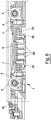
figure 6 show a view in larger scale of a central portion offigure 2 . - With reference to the above-mentioned
figures, 1 denotes in its entirety a supporting frame of a tool for removing aninternal weld bead 4 of a closed-section profile element constituted in the example by atube 2 obtained by welding. This tool is specifically structured for enabling adjustment of the cutting depth of abead remover 26 usable for the removal of saidweld bead 4 internally of thetube 2, which operation is commonly known as debeading. - The supporting frame 1 has an elongated shape and exhibits, together with the parts associated thereto, transverse dimensions enabling it to be contained internally of the
tube 2. The supporting frame 1 is associated, at anend 29 thereof, to an arm or rod, not illustrated in the accompanying figures, which projects from the open end of thetube 2 and is fixed externally thereof. - A plurality of
rolling elements 3 is constrained to the lower part of said supporting frame 1, whichrolling elements 3 are located at a pre-established mutual distance in a longitudinal direction. Therolling elements 3 partially project from the body of the supporting frame 1 and are predisposed to come into contact with the internal surface of thetube 2 in a diametrically-opposite zone to a zone whereon the internal weld bead 4 lies. - At least two
idle rollers 5 are predisposed superiorly of the supporting frame 1, whichrollers 5 are arranged longitudinally at a pre-established distance from one another and are mounted on small frames orlevers 6 that are mobile in a transverse direction with respect to the longitudinal axis of the supporting frame 1 so as to be positionable in any position comprised from at least an active position, at which therollers 5 are in contact with the inner surface of thetube 2 in proximity of theinternal weld bead 4, to at least an inactive position, at which therollers 5 are not in contact with the inner surface of thetube 2. - The
idle rollers 5 are arranged longitudinally, i.e. parallel to the longitudinal axis of the device, at a pre-established distance from one another on a same axial plane and exhibit an external rolling surface thereof profiled with acentral groove 25 dimensioned so as to house the saidinternal weld bead 4 internally thereof. - The
wheels 5 are commanded to carry out the transverse displacements thereof by command of a command mechanism havinginclined surfaces 7. - Said command mechanism having
inclined surfaces 7 is activated by a hydrauliclinear actuator 8. - The
inclined surfaces 7 exhibit an identical inclination to the longitudinal axis of the supporting frame 1 and are solidly constrained onslides 9 which are longitudinally slidable with respect to the body of the supporting frame 1 and mechanically connected, by astem 10, to thepiston 11 of the hydrauliclinear actuator 8 so that a longitudinal displacement of both theinclined surfaces 7 produces a transverse displacement of therollers 5 in the same direction. - The
rollers 5 are in fact rotatably mounted onsmall frames 6 or levers which at an end thereof are pivoted onposts 31 fixed to the supporting frame 1, while on the other end thereof they are predisposed to interact in contact with the respectiveinclined surfaces 7. In this way an axial displacement of theinclined surfaces 7 produces a rotation by a same entity, but in an opposite direction, of thesmall frames 6 or levers which in turn generates identical transverse displacements of thewheels 5. - The
piston 11 divides the internal volume of thecylinder 27 of the hydrauliclinear actuator 8 into twomanoeuvring chambers hydraulic conduits figure 1 , to twocorresponding command chambers hydraulic command cylinder 14, which is part of anexternal control console 15 and is provided with acontrol piston 16. - The
control piston 16 is provided with at least acontrol rod 17 on an end of which, external of thehydraulic control cylinder 14, anoperative adjustment knob 18 operates for enabling realization of the axial displacement in the two directions of thecontrol rod 17 and thecontrol piston 16 connected thereto with respect to thehydraulic control cylinder 14. - The
adjustment knob 18 is axially constrained and is coupled to the said end of thecontrol rod 17 by means of a coupling comprising anoperating screw 19. - The whole hydraulic circuit connecting the
manoeuvring chambers corresponding control chambers - The two
control chambers hydraulic control cylinder 14 can be, as for example is represented in the illustrated embodiment, exactly corresponding in terms of dimensions and capacity to the twomanoeuvring chambers linear actuator 8. The dimensions and capacities of thecontrol chambers manoeuvring chambers control chambers corresponding control chamber control piston 16. Therefore a finer adjustment of the axial displacement of theinclined surfaces 7 can be made, and therefore therollers 5 can exploit a greater sensitivity of adjustment i.e. greater axial displacements of thecontrol piston 16. - An
indicator 20 is solidly connected to thecontrol rod 17 of thecontrol piston 16, whichindicator 20 operates on a fixed graduated scale 21 so as to indicate the displacements of thecontrol piston 16 and consequently the axial displacements of thepiston 11 commanding the transverse displacements of therollers 5. - The plurality of
rolling elements 3 comprises two pairs ofsmall idle rollers 30 mounted on amobile frame 24; thesmall idle rollers 30 of each pair is flanked and arranged with relative axes that are not parallel to one another and lying on a transverse plane to the axis of the supporting frame 1. - The
mobile frame 24 is constrained to undergo guided displacements in a transverse direction with respect to the supporting frame 1 by action of contrast means 28. This enables the whole tool to rest with theidle rollers 30 on the internal surface of thetube 2 in a diametrically-opposite position to the position against which therollers 5 go to operate, thus realizing an adequate contrast. The contrast means 28 can be hydraulically-activated, pneumatically-activated or even elastic, by means of springs. - At least a
bead remover tool 26 is solidly fixed to the supporting frame 1 on the same axial plane in which therollers 5 are contained. - The assembly constituted by the
rolling elements 3, located in the lower part of the supporting frame 1, and therollers 5 is located, in an axial direction, in an opposite position to the cutting edge of thebead remover tool 26 with respect to an ideal plane perpendicular to the longitudinal axis of the supporting frame 1 and tangential to said cutting edge. - In the operation of the invention, in the initial step the
rollers 5 are in a pre-established position. Once the welder is activated, which fuses the edges of the tube that are flanked to one another, thecontrast elements 28 are activated to work on themobile frame 24, transversely distancing from the body of the device and operating the descent up to when therolling elements 3 arrive in contact with the lower zone of the internal surface of thetube 2. In this way a sort of expansion occurs which proceeds up to when all therolling elements 3 and therollers 5 are solidly in contact with the respective zones of the internal surface of thetube 2. - In this position, via the
hydraulic control cylinder 14 the hydrauliclinear actuator 8 is actuated to produce the transverse displacement of therollers 5, thus adjusting the relative position with respect thereto of thebead remover tool 26 and, consequently, the depth of the cut. - In the above-mentioned active configuration, i.e. with the tool in the work position, as schematically represented in
figure 1 , by actuating the hydrauliclinear actuator 8, theinclined surfaces 7 slide on theslides 9 and interact with the small frames or levers (6), causing a raising of thewheels 5. - By simply acting on the
hydraulic control cylinder 14 it is thus possible to adjust and regulate the work position of the bead remover tool with respect to thetube 2 and to theinternal weld bead 4. The displacements of thepiston 16 translate, by effect of the hydraulic connection between thehydraulic control cylinder 14 and the cylinder of thelinear actuator 8 and the consequent action exerted by theinclined surfaces 7 on therollers 5, into a displacement of therollers 5 that is transverse with respect to the axis of thetube 2. - This displacement is determined proportionally to the displacement induced by the
control piston 16. - The adjusting of the cutting depth is in fact essentially determined by the radial distance with respect to the axis of the
tube 2 which is realised between the cutting of thetool 26 and the rolling surfaces of therollers 5. - The
small idle rollers 30 act in opposition, contributing to maintaining the centred position of the tool with respect to thetube element 2. - The eventual insertion between the rod (not illustrated) and the supporting frame 1 of sensors able to measure the longitudinal component of the traction force or the variations in acceleration during the carrying-out of the debeading operations can enable obtaining a signalling of possible faults and thus correcting them by acting on the adjustment on the basis of the invention.
Claims (11)
- A device for adjusting cutting depth for the removal of longitudinal weld beads inside sections such as tubes and the like, comprising:- a supporting frame (1) of an elongated shape and transverse dimensions suitable for enabling it to be contained inside a section (2), the supporting frame (1) being associated, at one end thereof, with an arm or external rod;- a bead remover tool (26) solidly fixed to the supporting frame (1), wherein the bead remover tool (26) is fixed to the supporting frame (1) on the same axial plane in which the rollers (5) are contained;- at least two rollers (5), which are idle, arranged longitudinally at a pre-established distance from each other;characterised in that the device comprises:- a plurality of rolling elements (3) associated with said supporting frame (1) at a pre-established mutual distance in a longitudinal direction and that partially project out from the body of the same supporting frame and are capable of coming into contact with the inner surface of the section or tube (2) in a zone that is diametrically opposite the one whereon the internal weld bead (4) lies;- wherein said rollers (5) are mounted on small frames (6) that are movable in transverse directions with respect to the longitudinal axis of the supporting frame (1) from an active position, wherein the rollers (5) are in contact with the inner surface of the section or tube (2) in the proximity of the internal weld bead (4), to an inactive position, wherein the rollers (5) are not in contact with this inner surface of the section or tube (2), said rollers being commanded to shift transversely by a control mechanism having inclined surfaces (7).
- The device for adjusting cutting depth according to claim 1, characterized in that said control mechanism having inclined surfaces (7) is activated by a hydraulic linear actuator (8).
- The device for adjusting cutting depth according to claim 2, characterized in that said inclined surfaces (7) have the same inclination with respect to the longitudinal axis of the supporting frame (1) and are solidly constrained to slides (9), which are longitudinally slidable with respect to the body of the supporting frame (1) and mechanically connected to the piston (11) of the hydraulic linear actuator (8) by means of a stem (10).
- The device for adjusting cutting depth according to one of the preceding claims, characterized in that the at least two rollers (5) are idle, longitudinally arranged at a pre-established distance from each other on the same axial plane and the external rolling surface thereof is shaped with a central groove (25) that is dimensioned so as to house said internal weld bead (4) therein.
- The device for adjusting cutting depth according to the preceding claim, characterized in that the rollers (5) are mounted rotatably on small frames or levers (6), which, with a first end thereof, are pivoted on posts (31) fixed to the supporting frame (1), whereas the other end thereof is free and predisposed to interact in contact with the respective inclined surfaces (7); said rollers (5) can be positioned in any position ranging between an active position, wherein the rollers (5) are in contact with the inner surface of the tube (2) in the proximity of the internal weld bead (4), and at least one inactive position, wherein the rollers (5) are not in contact with this inner surface of the tube (2).
- The device for adjusting cutting depth according to one of claims 3 to 5, characterized in that the piston (11) divides the internal volume of the cylinder of the hydraulic linear actuator (8) into two manoeuvring chambers (12) and (13), which are connected in a like manner, by means of hydraulic conduits (22) and (23) to two corresponding control chambers (32) and (33) of a hydraulic control cylinder (14), which is part of a control console (15) and is equipped with a control piston (16); the control piston (16) being equipped with at least one control rod (17) and on one end thereof, outside of the hydraulic cylinder (14), there is an operative adjustment knob (18) suitable for enabling axial shifting of the control rod (17) and the control piston (16) connected to it, in the two directions with respect to the hydraulic control cylinder (14).
- The device for adjusting cutting depth according to claim 6, characterized in that the adjustment knob (18) is axially constrained and coupled to said end of the control rod (17) by means of coupling comprising an operating screw (19).
- The device for adjusting cutting depth according to claim 7, characterized in that the entire hydraulic circuit connecting the manoeuvring chambers (12) and (13) with the corresponding control chambers (32) and (33) is closed.
- The device for adjusting cutting depth according to claim 8, characterized in that an indicator (20) is solidly connected to the rod (17) of the control piston (16) and said indicator (20) operates on a fixed graduated scale (21) so as to indicate the shifting of the control piston (14).
- The device for adjusting cutting depth according to one of the preceding claims, characterized in that said plurality of rolling elements (3) comprises two pairs of small idle rollers (30) mounted on a movable frame (24); the small idle wheels (30) in each pair are side by side and arranged with axes that are not parallel to each other and lying on a plane transverse to the axis of the supporting frame (1), said movable frame (24) being constrained so as to undergo guided shifting, by means of contrast elements (28), in a transverse direction with respect to the supporting frame (1).
- The device for adjusting cutting depth according to one of the preceding claims, characterized in that it comprises at least one bead remover tool (26); the overall device being constituted by the plurality of rolling elements (3), which are placed in the lower part of said supporting frame (1), and said rollers (5), being located, in an axial direction, in a position opposite the cutting edge of the tool (26) with respect to an ideal plane perpendicular to the longitudinal axis of the supporting frame (1) and tangent to said cutting edge.
Applications Claiming Priority (1)
| Application Number | Priority Date | Filing Date | Title |
|---|---|---|---|
| ITMO20140004 | 2014-01-09 |
Publications (2)
| Publication Number | Publication Date |
|---|---|
| EP2893999A1 EP2893999A1 (en) | 2015-07-15 |
| EP2893999B1 true EP2893999B1 (en) | 2019-02-13 |
Family
ID=50116037
Family Applications (1)
| Application Number | Title | Priority Date | Filing Date |
|---|---|---|---|
| EP14196036.9A Active EP2893999B1 (en) | 2014-01-09 | 2014-12-03 | A device for adjusting cutting depth for removal of weld beads inside profile sections such as tubes and the like. |
Country Status (8)
| Country | Link |
|---|---|
| US (1) | US9486868B2 (en) |
| EP (1) | EP2893999B1 (en) |
| JP (1) | JP6153548B2 (en) |
| BR (1) | BR102015000260A2 (en) |
| CA (1) | CA2874134C (en) |
| ES (1) | ES2715695T3 (en) |
| MX (1) | MX357988B (en) |
| TR (1) | TR201903208T4 (en) |
Families Citing this family (5)
| Publication number | Priority date | Publication date | Assignee | Title |
|---|---|---|---|---|
| KR102124135B1 (en) * | 2018-11-20 | 2020-08-27 | 주식회사 케이티엠테크 | Exterior and inner bead removal roll stand for metal welding |
| CN112975179B (en) * | 2021-02-25 | 2022-08-26 | 中车长春轨道客车股份有限公司 | Motor train unit section bar cavity welding deformation control device and control method |
| JP7493127B2 (en) | 2021-03-17 | 2024-05-31 | Jfeスチール株式会社 | Device and method for grinding inner bead of square column, and method for manufacturing square column |
| CN114311332B (en) * | 2021-11-16 | 2024-07-05 | 海洋石油工程股份有限公司 | A new and efficient grooving device for concrete counterweight layer of submarine pipeline |
| CN115890250B (en) * | 2022-10-28 | 2025-07-18 | 定南色耐特智能科技股份有限公司 | Welding device for curled plate unit |
Family Cites Families (25)
| Publication number | Priority date | Publication date | Assignee | Title |
|---|---|---|---|---|
| US2237550A (en) * | 1939-01-24 | 1941-04-08 | Republic Steel Corp | Inside flash cutter |
| US2900879A (en) * | 1955-03-18 | 1959-08-25 | Tube Prod Ltd | Manufacture of seam-welded tubing |
| US2923208A (en) * | 1956-06-13 | 1960-02-02 | Babcock & Wilcox Co | Bead cutter mounting for inside bead trimmer |
| JPS4729663Y1 (en) * | 1968-09-04 | 1972-09-05 | ||
| GB1339598A (en) * | 1971-09-21 | 1973-12-05 | British Steel Corp | Internal bead trimmers |
| US3819898A (en) * | 1972-04-21 | 1974-06-25 | Olin Corp | Adjustable scarfing tool |
| US3834275A (en) * | 1973-07-25 | 1974-09-10 | Gen Motors Corp | Weld bead removal procedure |
| JPS51134990A (en) * | 1975-05-14 | 1976-11-22 | Erekutorosutarusukii Zaboodo C | Head for cutting casting fins on vertical directional inner surface of inner surface of welded tube |
| DE2940874C2 (en) * | 1979-10-09 | 1982-12-23 | Techno ARBED Deutschland GmbH, 6600 Saarbrücken | Device for internal deburring of longitudinally welded pipes |
| JPS5813284B2 (en) * | 1979-10-20 | 1983-03-12 | 新日本製鐵株式会社 | Internal bead cutting device for ERW pipes |
| DE3119943C2 (en) * | 1981-05-15 | 1986-06-26 | Mannesmann AG, 4000 Düsseldorf | Device for internal deburring of longitudinally welded pipes |
| DE3347146C1 (en) * | 1983-12-27 | 1985-03-14 | Techno ARBED Deutschland GmbH, 6600 Saarbrücken | Device for internal deburring of longitudinally welded pipes or profiles |
| JPS61109614U (en) * | 1984-12-25 | 1986-07-11 | ||
| JPS61192409A (en) * | 1985-02-20 | 1986-08-27 | Mitsubishi Heavy Ind Ltd | Removing device of projections in pipe shaped body |
| US4682921A (en) * | 1985-11-08 | 1987-07-28 | Pittsburgh Tube Company | Inside-tube scarfing tool |
| JPS62105712U (en) * | 1985-12-25 | 1987-07-06 | ||
| JPH0691437B2 (en) | 1987-01-09 | 1994-11-14 | 工業技術院長 | Method of generating large shock current using capacitor |
| JPH0422890Y2 (en) * | 1987-04-27 | 1992-05-27 | ||
| WO1988009231A1 (en) * | 1987-05-29 | 1988-12-01 | Uralsky Nauchno-Issledovatelsky Institut Trubnoi P | Device for removing internal burrs in welded pipes |
| JPH0533206Y2 (en) * | 1987-12-28 | 1993-08-24 | ||
| US5216792A (en) | 1990-06-30 | 1993-06-08 | Hoesch Aktiengesellschaft | Method of and device for obtaining short shavings trimmed from the seams inside longitudinally welded pipes |
| US5056972A (en) * | 1990-09-07 | 1991-10-15 | Nelson Tool Corporation | Deburring device |
| JPH10337609A (en) * | 1997-06-06 | 1998-12-22 | Izumi Shoji Kk | Method and apparatus for remotely operating internal bead cutting of steel pipe |
| JPH1133814A (en) * | 1997-07-22 | 1999-02-09 | Nkk Corp | Internal bead cutting device for ERW pipe |
| JP2002018633A (en) * | 2000-07-05 | 2002-01-22 | Nisshin Koki Kk | Cutting device for inner surface bead in facility for manufacturing pipe by high-frequency welding |
-
2014
- 2014-12-03 TR TR2019/03208T patent/TR201903208T4/en unknown
- 2014-12-03 ES ES14196036T patent/ES2715695T3/en active Active
- 2014-12-03 EP EP14196036.9A patent/EP2893999B1/en active Active
- 2014-12-08 US US14/563,417 patent/US9486868B2/en not_active Expired - Fee Related
- 2014-12-09 CA CA2874134A patent/CA2874134C/en not_active Expired - Fee Related
-
2015
- 2015-01-07 BR BR102015000260A patent/BR102015000260A2/en not_active Application Discontinuation
- 2015-01-08 MX MX2015000339A patent/MX357988B/en active IP Right Grant
- 2015-01-08 JP JP2015002584A patent/JP6153548B2/en not_active Expired - Fee Related
Non-Patent Citations (1)
| Title |
|---|
| None * |
Also Published As
| Publication number | Publication date |
|---|---|
| JP2015131345A (en) | 2015-07-23 |
| CA2874134C (en) | 2018-02-20 |
| BR102015000260A2 (en) | 2016-09-13 |
| TR201903208T4 (en) | 2019-06-21 |
| MX2015000339A (en) | 2015-07-17 |
| ES2715695T3 (en) | 2019-06-05 |
| MX357988B (en) | 2018-07-31 |
| JP6153548B2 (en) | 2017-06-28 |
| US9486868B2 (en) | 2016-11-08 |
| US20150190873A1 (en) | 2015-07-09 |
| EP2893999A1 (en) | 2015-07-15 |
| CA2874134A1 (en) | 2015-07-09 |
Similar Documents
| Publication | Publication Date | Title |
|---|---|---|
| US9486868B2 (en) | Device for adjusting cutting depth for removal of weld beads inside profile sections such as tubes and the like | |
| JP5801950B2 (en) | Manufacturing method and manufacturing apparatus for flange-free drawn parts | |
| EP3479943B1 (en) | Cutting-off machine to cut section bars, in particular made of aluminium, light alloys, pvc or the like | |
| BR112019023914A2 (en) | FOLDING MACHINE FOR METAL PLATES | |
| EP2845660B1 (en) | Automated tube straightening apparatus and method forstraightening a tube | |
| ES2905725T3 (en) | Method and forming device for the manufacture of a sheet metal component that has flanges | |
| ITBO20070538A1 (en) | PIECE PROCESSING DEVICE, IN PARTICULAR AERONAUTICAL PIECES OBTAINED FROM BLOCKS FULL OF RAW MATERIAL. | |
| CN105904768B (en) | A kind of automatic indentation system of corrugated paper for being used to produce packing case | |
| JP5393358B2 (en) | Plate bending press | |
| CA1037505A (en) | Stop mechanism for a bending press, plate shear or the like machines | |
| EP3127875B1 (en) | Cutting machine for cutting a glass sheet | |
| CN1325233C (en) | Rigid Floating Cutting Equipment | |
| AU2010206120A1 (en) | Method of measuring a length of sections of extrados or intrados curves of an elongated workpiece, and relevant length measuring instrument | |
| PT2077165E (en) | Sheet metal bending machine | |
| EP2827092B1 (en) | Cartridge loading machine with quick caliber change system | |
| SE526757C2 (en) | Locking device with movable backdrop | |
| CN204307995U (en) | A kind of copper bar bending device | |
| US2803226A (en) | Controlling mechanism for the toolholder of a machine-tool | |
| EP2325498B1 (en) | Fluid-dynamic circuit | |
| KR20120052930A (en) | Machine for making gears | |
| JP6397713B2 (en) | Tracking device | |
| KR101580476B1 (en) | Mold clamping device for press | |
| CA3020417C (en) | Device for producing reinforcements | |
| JP5659874B2 (en) | Machining diameter correction device | |
| ITTO960732A1 (en) | ADJUSTMENT DEVICE FOR A FOLDING GUIDE IN A SEWING MACHINE |
Legal Events
| Date | Code | Title | Description |
|---|---|---|---|
| PUAI | Public reference made under article 153(3) epc to a published international application that has entered the european phase |
Free format text: ORIGINAL CODE: 0009012 |
|
| 17P | Request for examination filed |
Effective date: 20141203 |
|
| AK | Designated contracting states |
Kind code of ref document: A1 Designated state(s): AL AT BE BG CH CY CZ DE DK EE ES FI FR GB GR HR HU IE IS IT LI LT LU LV MC MK MT NL NO PL PT RO RS SE SI SK SM TR |
|
| AX | Request for extension of the european patent |
Extension state: BA ME |
|
| R17P | Request for examination filed (corrected) |
Effective date: 20150612 |
|
| RBV | Designated contracting states (corrected) |
Designated state(s): AL AT BE BG CH CY CZ DE DK EE ES FI FR GB GR HR HU IE IS IT LI LT LU LV MC MK MT NL NO PL PT RO RS SE SI SK SM TR |
|
| STAA | Information on the status of an ep patent application or granted ep patent |
Free format text: STATUS: EXAMINATION IS IN PROGRESS |
|
| 17Q | First examination report despatched |
Effective date: 20180416 |
|
| RIC1 | Information provided on ipc code assigned before grant |
Ipc: B23D 1/08 20060101ALI20180919BHEP Ipc: B23D 1/00 20060101ALI20180919BHEP Ipc: B23D 1/24 20060101ALI20180919BHEP Ipc: B21C 37/08 20060101ALI20180919BHEP Ipc: B23D 1/10 20060101ALI20180919BHEP Ipc: B23D 79/02 20060101AFI20180919BHEP Ipc: B23D 1/26 20060101ALI20180919BHEP |
|
| GRAP | Despatch of communication of intention to grant a patent |
Free format text: ORIGINAL CODE: EPIDOSNIGR1 |
|
| STAA | Information on the status of an ep patent application or granted ep patent |
Free format text: STATUS: GRANT OF PATENT IS INTENDED |
|
| INTG | Intention to grant announced |
Effective date: 20181031 |
|
| GRAS | Grant fee paid |
Free format text: ORIGINAL CODE: EPIDOSNIGR3 |
|
| GRAA | (expected) grant |
Free format text: ORIGINAL CODE: 0009210 |
|
| STAA | Information on the status of an ep patent application or granted ep patent |
Free format text: STATUS: THE PATENT HAS BEEN GRANTED |
|
| AK | Designated contracting states |
Kind code of ref document: B1 Designated state(s): AL AT BE BG CH CY CZ DE DK EE ES FI FR GB GR HR HU IE IS IT LI LT LU LV MC MK MT NL NO PL PT RO RS SE SI SK SM TR |
|
| REG | Reference to a national code |
Ref country code: GB Ref legal event code: FG4D |
|
| REG | Reference to a national code |
Ref country code: CH Ref legal event code: EP Ref country code: AT Ref legal event code: REF Ref document number: 1095919 Country of ref document: AT Kind code of ref document: T Effective date: 20190215 |
|
| REG | Reference to a national code |
Ref country code: IE Ref legal event code: FG4D |
|
| REG | Reference to a national code |
Ref country code: DE Ref legal event code: R096 Ref document number: 602014040950 Country of ref document: DE |
|
| REG | Reference to a national code |
Ref country code: ES Ref legal event code: FG2A Ref document number: 2715695 Country of ref document: ES Kind code of ref document: T3 Effective date: 20190605 |
|
| REG | Reference to a national code |
Ref country code: LT Ref legal event code: MG4D |
|
| REG | Reference to a national code |
Ref country code: NL Ref legal event code: MP Effective date: 20190213 |
|
| PG25 | Lapsed in a contracting state [announced via postgrant information from national office to epo] |
Ref country code: FI Free format text: LAPSE BECAUSE OF FAILURE TO SUBMIT A TRANSLATION OF THE DESCRIPTION OR TO PAY THE FEE WITHIN THE PRESCRIBED TIME-LIMIT Effective date: 20190213 Ref country code: SE Free format text: LAPSE BECAUSE OF FAILURE TO SUBMIT A TRANSLATION OF THE DESCRIPTION OR TO PAY THE FEE WITHIN THE PRESCRIBED TIME-LIMIT Effective date: 20190213 Ref country code: NL Free format text: LAPSE BECAUSE OF FAILURE TO SUBMIT A TRANSLATION OF THE DESCRIPTION OR TO PAY THE FEE WITHIN THE PRESCRIBED TIME-LIMIT Effective date: 20190213 Ref country code: LT Free format text: LAPSE BECAUSE OF FAILURE TO SUBMIT A TRANSLATION OF THE DESCRIPTION OR TO PAY THE FEE WITHIN THE PRESCRIBED TIME-LIMIT Effective date: 20190213 Ref country code: PT Free format text: LAPSE BECAUSE OF FAILURE TO SUBMIT A TRANSLATION OF THE DESCRIPTION OR TO PAY THE FEE WITHIN THE PRESCRIBED TIME-LIMIT Effective date: 20190613 Ref country code: NO Free format text: LAPSE BECAUSE OF FAILURE TO SUBMIT A TRANSLATION OF THE DESCRIPTION OR TO PAY THE FEE WITHIN THE PRESCRIBED TIME-LIMIT Effective date: 20190513 |
|
| PG25 | Lapsed in a contracting state [announced via postgrant information from national office to epo] |
Ref country code: RS Free format text: LAPSE BECAUSE OF FAILURE TO SUBMIT A TRANSLATION OF THE DESCRIPTION OR TO PAY THE FEE WITHIN THE PRESCRIBED TIME-LIMIT Effective date: 20190213 Ref country code: HR Free format text: LAPSE BECAUSE OF FAILURE TO SUBMIT A TRANSLATION OF THE DESCRIPTION OR TO PAY THE FEE WITHIN THE PRESCRIBED TIME-LIMIT Effective date: 20190213 Ref country code: GR Free format text: LAPSE BECAUSE OF FAILURE TO SUBMIT A TRANSLATION OF THE DESCRIPTION OR TO PAY THE FEE WITHIN THE PRESCRIBED TIME-LIMIT Effective date: 20190514 Ref country code: LV Free format text: LAPSE BECAUSE OF FAILURE TO SUBMIT A TRANSLATION OF THE DESCRIPTION OR TO PAY THE FEE WITHIN THE PRESCRIBED TIME-LIMIT Effective date: 20190213 Ref country code: IS Free format text: LAPSE BECAUSE OF FAILURE TO SUBMIT A TRANSLATION OF THE DESCRIPTION OR TO PAY THE FEE WITHIN THE PRESCRIBED TIME-LIMIT Effective date: 20190613 Ref country code: BG Free format text: LAPSE BECAUSE OF FAILURE TO SUBMIT A TRANSLATION OF THE DESCRIPTION OR TO PAY THE FEE WITHIN THE PRESCRIBED TIME-LIMIT Effective date: 20190513 |
|
| REG | Reference to a national code |
Ref country code: AT Ref legal event code: MK05 Ref document number: 1095919 Country of ref document: AT Kind code of ref document: T Effective date: 20190213 |
|
| PG25 | Lapsed in a contracting state [announced via postgrant information from national office to epo] |
Ref country code: EE Free format text: LAPSE BECAUSE OF FAILURE TO SUBMIT A TRANSLATION OF THE DESCRIPTION OR TO PAY THE FEE WITHIN THE PRESCRIBED TIME-LIMIT Effective date: 20190213 Ref country code: RO Free format text: LAPSE BECAUSE OF FAILURE TO SUBMIT A TRANSLATION OF THE DESCRIPTION OR TO PAY THE FEE WITHIN THE PRESCRIBED TIME-LIMIT Effective date: 20190213 Ref country code: CZ Free format text: LAPSE BECAUSE OF FAILURE TO SUBMIT A TRANSLATION OF THE DESCRIPTION OR TO PAY THE FEE WITHIN THE PRESCRIBED TIME-LIMIT Effective date: 20190213 Ref country code: SK Free format text: LAPSE BECAUSE OF FAILURE TO SUBMIT A TRANSLATION OF THE DESCRIPTION OR TO PAY THE FEE WITHIN THE PRESCRIBED TIME-LIMIT Effective date: 20190213 Ref country code: AL Free format text: LAPSE BECAUSE OF FAILURE TO SUBMIT A TRANSLATION OF THE DESCRIPTION OR TO PAY THE FEE WITHIN THE PRESCRIBED TIME-LIMIT Effective date: 20190213 Ref country code: DK Free format text: LAPSE BECAUSE OF FAILURE TO SUBMIT A TRANSLATION OF THE DESCRIPTION OR TO PAY THE FEE WITHIN THE PRESCRIBED TIME-LIMIT Effective date: 20190213 |
|
| REG | Reference to a national code |
Ref country code: DE Ref legal event code: R097 Ref document number: 602014040950 Country of ref document: DE |
|
| PG25 | Lapsed in a contracting state [announced via postgrant information from national office to epo] |
Ref country code: PL Free format text: LAPSE BECAUSE OF FAILURE TO SUBMIT A TRANSLATION OF THE DESCRIPTION OR TO PAY THE FEE WITHIN THE PRESCRIBED TIME-LIMIT Effective date: 20190213 Ref country code: SM Free format text: LAPSE BECAUSE OF FAILURE TO SUBMIT A TRANSLATION OF THE DESCRIPTION OR TO PAY THE FEE WITHIN THE PRESCRIBED TIME-LIMIT Effective date: 20190213 |
|
| PLBE | No opposition filed within time limit |
Free format text: ORIGINAL CODE: 0009261 |
|
| STAA | Information on the status of an ep patent application or granted ep patent |
Free format text: STATUS: NO OPPOSITION FILED WITHIN TIME LIMIT |
|
| PG25 | Lapsed in a contracting state [announced via postgrant information from national office to epo] |
Ref country code: AT Free format text: LAPSE BECAUSE OF FAILURE TO SUBMIT A TRANSLATION OF THE DESCRIPTION OR TO PAY THE FEE WITHIN THE PRESCRIBED TIME-LIMIT Effective date: 20190213 |
|
| 26N | No opposition filed |
Effective date: 20191114 |
|
| PG25 | Lapsed in a contracting state [announced via postgrant information from national office to epo] |
Ref country code: SI Free format text: LAPSE BECAUSE OF FAILURE TO SUBMIT A TRANSLATION OF THE DESCRIPTION OR TO PAY THE FEE WITHIN THE PRESCRIBED TIME-LIMIT Effective date: 20190213 |
|
| REG | Reference to a national code |
Ref country code: CH Ref legal event code: PL |
|
| REG | Reference to a national code |
Ref country code: BE Ref legal event code: MM Effective date: 20191231 |
|
| PG25 | Lapsed in a contracting state [announced via postgrant information from national office to epo] |
Ref country code: MC Free format text: LAPSE BECAUSE OF FAILURE TO SUBMIT A TRANSLATION OF THE DESCRIPTION OR TO PAY THE FEE WITHIN THE PRESCRIBED TIME-LIMIT Effective date: 20190213 |
|
| GBPC | Gb: european patent ceased through non-payment of renewal fee |
Effective date: 20191203 |
|
| PG25 | Lapsed in a contracting state [announced via postgrant information from national office to epo] |
Ref country code: FR Free format text: LAPSE BECAUSE OF NON-PAYMENT OF DUE FEES Effective date: 20191231 Ref country code: LU Free format text: LAPSE BECAUSE OF NON-PAYMENT OF DUE FEES Effective date: 20191203 Ref country code: GB Free format text: LAPSE BECAUSE OF NON-PAYMENT OF DUE FEES Effective date: 20191203 Ref country code: IE Free format text: LAPSE BECAUSE OF NON-PAYMENT OF DUE FEES Effective date: 20191203 |
|
| PG25 | Lapsed in a contracting state [announced via postgrant information from national office to epo] |
Ref country code: BE Free format text: LAPSE BECAUSE OF NON-PAYMENT OF DUE FEES Effective date: 20191231 Ref country code: CH Free format text: LAPSE BECAUSE OF NON-PAYMENT OF DUE FEES Effective date: 20191231 Ref country code: LI Free format text: LAPSE BECAUSE OF NON-PAYMENT OF DUE FEES Effective date: 20191231 |
|
| REG | Reference to a national code |
Ref country code: ES Ref legal event code: FD2A Effective date: 20210528 |
|
| PG25 | Lapsed in a contracting state [announced via postgrant information from national office to epo] |
Ref country code: CY Free format text: LAPSE BECAUSE OF FAILURE TO SUBMIT A TRANSLATION OF THE DESCRIPTION OR TO PAY THE FEE WITHIN THE PRESCRIBED TIME-LIMIT Effective date: 20190213 |
|
| PG25 | Lapsed in a contracting state [announced via postgrant information from national office to epo] |
Ref country code: MT Free format text: LAPSE BECAUSE OF FAILURE TO SUBMIT A TRANSLATION OF THE DESCRIPTION OR TO PAY THE FEE WITHIN THE PRESCRIBED TIME-LIMIT Effective date: 20190213 Ref country code: HU Free format text: LAPSE BECAUSE OF FAILURE TO SUBMIT A TRANSLATION OF THE DESCRIPTION OR TO PAY THE FEE WITHIN THE PRESCRIBED TIME-LIMIT; INVALID AB INITIO Effective date: 20141203 |
|
| PG25 | Lapsed in a contracting state [announced via postgrant information from national office to epo] |
Ref country code: ES Free format text: LAPSE BECAUSE OF NON-PAYMENT OF DUE FEES Effective date: 20191204 |
|
| PG25 | Lapsed in a contracting state [announced via postgrant information from national office to epo] |
Ref country code: MK Free format text: LAPSE BECAUSE OF FAILURE TO SUBMIT A TRANSLATION OF THE DESCRIPTION OR TO PAY THE FEE WITHIN THE PRESCRIBED TIME-LIMIT Effective date: 20190213 |
|
| PG25 | Lapsed in a contracting state [announced via postgrant information from national office to epo] |
Ref country code: TR Free format text: LAPSE BECAUSE OF NON-PAYMENT OF DUE FEES Effective date: 20191203 |
|
| PGFP | Annual fee paid to national office [announced via postgrant information from national office to epo] |
Ref country code: IT Payment date: 20241216 Year of fee payment: 11 |
|
| PGFP | Annual fee paid to national office [announced via postgrant information from national office to epo] |
Ref country code: DE Payment date: 20241227 Year of fee payment: 11 |