EP2893954A1 - System and method for generating simulated electrogram - Google Patents
System and method for generating simulated electrogram Download PDFInfo
- Publication number
- EP2893954A1 EP2893954A1 EP13834431.2A EP13834431A EP2893954A1 EP 2893954 A1 EP2893954 A1 EP 2893954A1 EP 13834431 A EP13834431 A EP 13834431A EP 2893954 A1 EP2893954 A1 EP 2893954A1
- Authority
- EP
- European Patent Office
- Prior art keywords
- electrode
- electrogram
- pseudo
- unipolar
- sectional area
- Prior art date
- Legal status (The legal status is an assumption and is not a legal conclusion. Google has not performed a legal analysis and makes no representation as to the accuracy of the status listed.)
- Withdrawn
Links
Images



Classifications
-
- G—PHYSICS
- G06—COMPUTING OR CALCULATING; COUNTING
- G06F—ELECTRIC DIGITAL DATA PROCESSING
- G06F17/00—Digital computing or data processing equipment or methods, specially adapted for specific functions
- G06F17/10—Complex mathematical operations
- G06F17/11—Complex mathematical operations for solving equations, e.g. nonlinear equations, general mathematical optimization problems
-
- A—HUMAN NECESSITIES
- A61—MEDICAL OR VETERINARY SCIENCE; HYGIENE
- A61N—ELECTROTHERAPY; MAGNETOTHERAPY; RADIATION THERAPY; ULTRASOUND THERAPY
- A61N1/00—Electrotherapy; Circuits therefor
- A61N1/18—Applying electric currents by contact electrodes
- A61N1/32—Applying electric currents by contact electrodes alternating or intermittent currents
- A61N1/36—Applying electric currents by contact electrodes alternating or intermittent currents for stimulation
- A61N1/362—Heart stimulators
- A61N1/365—Heart stimulators controlled by a physiological parameter, e.g. heart potential
-
- A—HUMAN NECESSITIES
- A61—MEDICAL OR VETERINARY SCIENCE; HYGIENE
- A61B—DIAGNOSIS; SURGERY; IDENTIFICATION
- A61B5/00—Measuring for diagnostic purposes; Identification of persons
- A61B5/24—Detecting, measuring or recording bioelectric or biomagnetic signals of the body or parts thereof
- A61B5/316—Modalities, i.e. specific diagnostic methods
- A61B5/318—Heart-related electrical modalities, e.g. electrocardiography [ECG]
- A61B5/319—Circuits for simulating ECG signals
-
- A—HUMAN NECESSITIES
- A61—MEDICAL OR VETERINARY SCIENCE; HYGIENE
- A61B—DIAGNOSIS; SURGERY; IDENTIFICATION
- A61B5/00—Measuring for diagnostic purposes; Identification of persons
-
- A—HUMAN NECESSITIES
- A61—MEDICAL OR VETERINARY SCIENCE; HYGIENE
- A61B—DIAGNOSIS; SURGERY; IDENTIFICATION
- A61B5/00—Measuring for diagnostic purposes; Identification of persons
- A61B5/72—Signal processing specially adapted for physiological signals or for diagnostic purposes
- A61B5/7271—Specific aspects of physiological measurement analysis
- A61B5/7278—Artificial waveform generation or derivation, e.g. synthesizing signals from measured signals
-
- G—PHYSICS
- G16—INFORMATION AND COMMUNICATION TECHNOLOGY [ICT] SPECIALLY ADAPTED FOR SPECIFIC APPLICATION FIELDS
- G16H—HEALTHCARE INFORMATICS, i.e. INFORMATION AND COMMUNICATION TECHNOLOGY [ICT] SPECIALLY ADAPTED FOR THE HANDLING OR PROCESSING OF MEDICAL OR HEALTHCARE DATA
- G16H50/00—ICT specially adapted for medical diagnosis, medical simulation or medical data mining; ICT specially adapted for detecting, monitoring or modelling epidemics or pandemics
- G16H50/50—ICT specially adapted for medical diagnosis, medical simulation or medical data mining; ICT specially adapted for detecting, monitoring or modelling epidemics or pandemics for simulation or modelling of medical disorders
Definitions
- the present invention relates to a system and method for generating a pseudo electrogram, and more particularly, to a system and method for generating a pseudo electrogram for use in generation of a complex fractionated atrial electrogram (CFAE).
- CFAE complex fractionated atrial electrogram
- Cardiac arrhythmia is a rhythm disease of the heart in which the pulse is slower or faster than normal, or is irregular.
- Atrial fibrillation is a very common type of cardiac arrhythmia and is a refractory disease, and it is estimated that about 1.6 % of the population in Korea has the atrial fibrillation.
- the atrial fibrillation is a disease in which older people, especially 60 years old or more, are affected, and it has increased in younger people recently, and is not uncommon in cases which have a common family history.
- Atrial fibrillation Another characteristic of the atrial fibrillation is that the case of not feeling symptoms reaches to about 20 %.
- the risk of an ischemic stroke a cerebral infarction
- people without symptoms break down sometimes due to the stroke which is complicated by the atrial fibrillation.
- the atrial fibrillation is also an intractable arrhythmia that is difficult to treat as well as is often delayed in diagnosing.
- Treatments of the atrial fibrillation may be largely divided into three categories. The first is an antithrombotic therapy which prevents the strokes, the second is a therapy which relieves symptoms by adjusting the pulse so as not to accelerate, and the third is a fundamental therapy which eliminates the atrial fibrillation and maintains a normal pulse.
- a treatment developed to overcome the low efficiency and the risk of adverse effects of antiarrhythmic drugs as a fundamental therapy is called radiofrequency catheter ablation.
- the radiofrequency catheter ablation is a treatment developed so as to simplify the maze surgery which is originally used when heart surgeons perform heart valve surgeries.
- the radiofrequency catheter ablation has a recurrence rate, however, a cure rate of paroxysmal atrial fibrillation grows in a range of 85 % to 90 %, and it is possible to completely cure persistent atrial fibrillation in a range of 70 % to 75 %.
- the radiofrequency catheter ablation for the treatment of the cardiac arrhythmias is a method of performing a treatment so that electrical activities of the heart can be normally achieved by damaging the patient's heart tissues, however, there is a problem in that it is difficult to revive the damaged heart tissues. Therefore, an area in which the radiofrequency catheter ablation will be performed should be very carefully selected, and there is plenty of room for improvement in a mapping method and an ablation method.
- the present invention is directed to a system and method for generating a pseudo electrogram in which an electrogram for inducing a complex fractionated atrial electrogram is non-invasively generated using a pseudo electrode, and location data for performing radiofrequency catheter ablation is provided through the electrogram, electrical physiological activities found in the heart of a patient during surgery are predicted, and then a result of the prediction is predicted and diagnosed.
- a system for generating a pseudo electrogram including: a unipolar electrogram generation unit which generates a unipolar electrogram according to an action potential calculated from an electric physiological model of the heart using a pseudo electrode of which a cross-sectional area is adjusted; and a pseudo electrogram generation unit which generates a pseudo electrogram using the unipolar electrogram.
- the pseudo electrode may include a first electrode and a second electrode.
- the unipolar electrogram generation unit may generate the unipolar electrogram according to the following equation.
- S 1 a cross-sectional area of an electrode
- S 2 a cross-sectional area of a unit cell
- x 0 a location of a tip of a pseudo electrode on an x-axis
- k the number of cells occupied by the electrode on the x-axis
- y 0 a location of a tip of a pseudo electrode on a y-axis
- 1 the number of cells occupied by the electrode on the y-axis
- V an action potential
- the pseudo electrogram generation unit may calculate the pseudo electrogram using a difference between a unipolar electrogram of the first electrode and a unipolar electrogram of the second electrode.
- the system may further include a filtering unit which filters only a signal in a predetermined frequency range from the pseudo electrogram.
- the filtering unit may filter only a signal in a frequency range of 30 Hz to 300 Hz.
- a method for generating a pseudo electrogram including: generating a unipolar electrogram according to an action potential calculated from an electric physiological model of the heart using a pseudo electrode in which a cross-sectional area is adjusted; and generating a pseudo electrogram using the unipolar electrogram.
- the generating of the unipolar electrogram may generate the unipolar electrogram according to the following equation.
- S 1 a cross-sectional area of an electrode
- S 2 a cross-sectional area of a unit cell
- x 0 a location of a tip of a pseudo electrode on an x-axis
- k the number of cells occupied by the electrode on the x-axis
- y 0 a location of a tip of a pseudo electrode on a y-axis
- 1 the number of cells occupied by the electrode on the y-axis
- V an action potential
- the generating of the pseudo electrogram may calculate the pseudo electrogram using a difference between a unipolar electrogram of a first electrode and a unipolar electrogram of a second electrode.
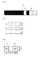
- FIG. 1 is a schematic view of a system for generating a pseudo electrogram according to an exemplary embodiment of the present invention
- FIG. 2 is a conceptual view of a pseudo electrode according to the exemplary embodiment of the present invention
- FIG. 3 is a conceptual view of a size of a cross-sectional area of the pseudo electrode according to the exemplary embodiment of the present invention.
- the system for generating the pseudo electrogram may include a unipolar electrogram generation unit 11 which generates a unipolar electrogram according to an action potential calculated from an electric physiological model of the heart using a pseudo electrode in which a cross-sectional area is adjusted according to a contact state, a pseudo electrogram generation unit 12 which generates a pseudo electrogram using the unipolar electrogram, and a filtering unit 13 which filters only signals in a predetermined frequency range from the pseudo electrogram.
- a unipolar electrogram generation unit 11 which generates a unipolar electrogram according to an action potential calculated from an electric physiological model of the heart using a pseudo electrode in which a cross-sectional area is adjusted according to a contact state
- a pseudo electrogram generation unit 12 which generates a pseudo electrogram using the unipolar electrogram
- a filtering unit 13 which filters only signals in a predetermined frequency range from the pseudo electrogram.
- the pseudo electrode according to the exemplary embodiment of the present invention may include a first electrode 21 and a second electrode 22.
- a cross-sectional area D of the pseudo electrode may be arbitrarily adjusted according to a contact state of an electrode.
- the cross-sectional area D of the pseudo electrode may be divided into three cases.
- the case of (a) shows a case in which the electrode contact state of the pseudo electrode is good, and in this case, it is preferable that the cross-sectional area D of the electrode is most largely adjusted.
- the case of (b) shows a case in which the electrode contact state of the pseudo electrode is generally good, and in this case, it is preferable that the cross-sectional area D of the electrode is set to be in an intermediate operation.
- the case of (c) shows a case in which the electrode contact state of the pseudo electrode is not good, and in this case, it is preferable that the cross-sectional area D of the electrode is minimally set.
- the cross-sectional area D of the pseudo electrode may be adjusted by the external setting.
- the unipolar electrogram generation unit 11 may generate a unipolar electrogram according to an action potential calculated from an electric physiological model of the heart using the pseudo electrode in which the cross-sectional area is adjusted according to the contact state.
- a method of calculating the action potential from the electric physiological model of the heart may use a ventricular cell model using the tenTusscher model, and an atrial model, which is based on the DiFrancesco and Noble models and uses the Nygren model partially made up of an LMCG model.
- the method of calculating the action potential from the electric physiological model of the heart may use other well-known techniques in addition to the above-described method, and detailed descriptions thereof will be omitted because it may obscure the gist of the invention.
- the unipolar electrogram generation unit 11 may generate the unipolar electrogram according to the following equation.
- S 1 a cross-sectional area of an electrode
- S 2 a cross-sectional area of a unit cell
- x 0 a location of a tip of a pseudo electrode on an x-axis
- k the number of cells occupied by the electrode on the x-axis
- y 0 a location of a tip of a pseudo electrode on a y-axis
- 1 the number of cells occupied by the electrode on the y-axis
- V an action potential
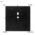
- FIG. 4 is a view showing settings of a cross-sectional area of a pseudo electrode according to an exemplary embodiment of the present invention
- FIG. 5 is a view showing an arrangement of the pseudo electrode according to the exemplary embodiment of the present invention
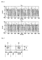
- FIG. 6 shows unipolar electrograms according to the exemplary embodiment of the present invention.
- the cross-sectional area of the pseudo electrode is set to 2 mm, and a length of the first electrode 21 and a length of the second electrode 22 are set to 2 mm and 3.5 mm, respectively.
- An area of the heart for generating the pseudo electrogram using the pseudo electrode is 25 ⁇ 25 (cm 2 ), an area of a unit cell is 0.25 ⁇ 0.25 (mm 2 ), and thus 1000 ⁇ 1000 unit cells may be distributed.
- the unipolar electrograms may be generated through the above-described process.
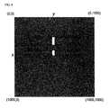
- FIG. 7 is a view showing settings of a cross-sectional area of a pseudo electrode according to another exemplary embodiment of the present invention
- FIG. 8 is a view showing an arrangement of the pseudo electrode according to the exemplary embodiment of the present invention
- FIG. 9 shows unipolar electrograms according to the exemplary embodiment of the present invention.
- the cross-sectional area of the pseudo electrode is set to 1 mm, and a length of the first electrode 21 and a length of the second electrode 22 are set to 2 mm and 3.5 mm, respectively.
- An area of the heart for generating the pseudo electrogram using the pseudo electrode is 25 ⁇ 25 (cm 2 ), an area of the unit cell is 0.25 ⁇ 0.25 (mm 2 ), and thus 1000 ⁇ 1000 unit cells may be distributed.
- the unipolar electrograms may be generated through the above-described process.
- FIG. 10 is a view showing settings of a cross-sectional area of a pseudo electrode according to still another exemplary embodiment of the present invention
- FIG. 11 is a view showing an arrangement of the pseudo electrode according to the exemplary embodiment of the present invention
- FIG. 12 shows unipolar electrograms according to the exemplary embodiment of the present invention.
- the cross-sectional area of the pseudo electrode is set to 0.25 mm, and a length of the first electrode 21 and a length of the second electrode 22 are set to 2 mm and 3.5 mm, respectively.
- An area of the heart for generating the pseudo electrogram using the pseudo electrode is 25 ⁇ 25 (cm 2 ), an area of the unit cell is 0.25 ⁇ 0.25 (mm 2 ), and thus 1000 ⁇ 1000 unit cells may be distributed.
- the unipolar electrograms may be generated through the above-described process.
- the pseudo electrogram generation unit 12 may calculate the pseudo electrogram using a difference between the unipolar electrogram of the first electrode 21 and the unipolar electrogram of the second electrode 22.
- FIG. 13 is a pseudo electrogram generated according to an exemplary embodiment of the present invention.
- the pseudo electrogram generation unit 12 may calculate the pseudo electrogram using Equation (2) through a difference between a first unipolar electrogram and a second unipolar electrogram which are calculated when an electrode contact state of the pseudo electrode is good.
- FIG. 14 is a pseudo electrogram generated according to another exemplary embodiment of the present invention.
- the pseudo electrogram generation unit 12 may calculate the pseudo electrogram using Equation (3) through a difference between a first unipolar electrogram and a second unipolar electrogram which are calculated when an electrode contact state of the pseudo electrode is generally good.
- FIG. 15 is a pseudo electrogram generated according to still another exemplary embodiment of the present invention.
- the pseudo electrogram generation unit 12 may calculate the pseudo electrogram using Equation (4) through a difference between a first unipolar electrogram and a second unipolar electrogram which are calculated when an electrode contact state of the pseudo electrode is not good.
- the filtering unit 13 may filter only signals in a predetermined frequency range from the pseudo electrogram and output the signals.
- the filtering unit 13 may filter only signals in a frequency range of 30 Hz to 500 Hz and output the signals, preferably may filter only signals in a frequency range of 30 Hz to 300 Hz and output the signals.
- FIG. 16 is a flowchart of a method for generating a pseudo electrogram according to an exemplary embodiment of the present invention.
- a unipolar electrogram is generated using an action potential calculated from the electric physiological model of the heart using a pseudo electrode in which a cross-sectional area is adjusted.
- the unipolar electrogram may be calculated by the following equation, and unipolar electrograms corresponding to the first electrode 21 and the second electrode 22 of the pseudo electrode, respectively, may be calculated (S1601).
- a pseudo electrogram may be generated using a difference between the unipolar electrogram of the first electrode 21 and the unipolar electrogram of the second electrode 22 (S1602).
- an electrogram for inducing a complex fractionated atrial electrogram can be non-invasively generated using a pseudo electrode.
- a pseudo electrogram generated using the pseudo electrode can be used for providing location data for performing radiofrequency catheter ablation, predicting electrical physiological activities found in the heart of a patient during surgery, and then predicting and diagnosing a result of the prediction.
- the term "unit” refers to software or a hardware component such as a field programmable gate array (FPGA) or an application specific integrated circuit (ASIC), which can perform certain functions.
- the unit is not limited to software or hardware.
- the unit may be configured in a recording medium which can be addressed or may be configured to execute at least one processor.
- Examples of the unit may include software components, object-oriented software components, class components, components such as task components, processes, functions, properties, procedures, subroutines, segments in program codes, drivers, firmware, microcode, circuits, data, databases, data structures, tables, arrays, and variables. Components and functions provided from units may be combined into a smaller number of components and units or may be separated into additional components and units.
- the components and units may execute at least one CPU in a device.
Landscapes
- Health & Medical Sciences (AREA)
- Engineering & Computer Science (AREA)
- Life Sciences & Earth Sciences (AREA)
- Public Health (AREA)
- Physics & Mathematics (AREA)
- Medical Informatics (AREA)
- Biomedical Technology (AREA)
- General Health & Medical Sciences (AREA)
- Pathology (AREA)
- Heart & Thoracic Surgery (AREA)
- Veterinary Medicine (AREA)
- Biophysics (AREA)
- Animal Behavior & Ethology (AREA)
- Molecular Biology (AREA)
- Surgery (AREA)
- Data Mining & Analysis (AREA)
- Cardiology (AREA)
- Mathematical Physics (AREA)
- General Physics & Mathematics (AREA)
- Databases & Information Systems (AREA)
- Physiology (AREA)
- Theoretical Computer Science (AREA)
- Mathematical Analysis (AREA)
- Pure & Applied Mathematics (AREA)
- Mathematical Optimization (AREA)
- Computational Mathematics (AREA)
- Artificial Intelligence (AREA)
- Primary Health Care (AREA)
- Epidemiology (AREA)
- Signal Processing (AREA)
- Psychiatry (AREA)
- Computer Vision & Pattern Recognition (AREA)
- Algebra (AREA)
- General Engineering & Computer Science (AREA)
- Software Systems (AREA)
- Operations Research (AREA)
- Nuclear Medicine, Radiotherapy & Molecular Imaging (AREA)
- Radiology & Medical Imaging (AREA)
- Measurement And Recording Of Electrical Phenomena And Electrical Characteristics Of The Living Body (AREA)
Abstract
Description
- This application claims priority to and the benefit of Korean Patent Application No.
2012-0099076, filed on Sep 07, 2012 - The present invention relates to a system and method for generating a pseudo electrogram, and more particularly, to a system and method for generating a pseudo electrogram for use in generation of a complex fractionated atrial electrogram (CFAE).
- Cardiac arrhythmia is a rhythm disease of the heart in which the pulse is slower or faster than normal, or is irregular. Atrial fibrillation is a very common type of cardiac arrhythmia and is a refractory disease, and it is estimated that about 1.6 % of the population in Korea has the atrial fibrillation. The atrial fibrillation is a disease in which older people, especially 60 years old or more, are affected, and it has increased in younger people recently, and is not uncommon in cases which have a common family history.
- Another characteristic of the atrial fibrillation is that the case of not feeling symptoms reaches to about 20 %. However, in the case of the atrial fibrillation, since the risk of an ischemic stroke (a cerebral infarction) is in a range of 5 % to 10 % per year (in a range of 15 % to 20 % of total cerebral infarction patients), people without symptoms break down sometimes due to the stroke which is complicated by the atrial fibrillation. As such, the atrial fibrillation is also an intractable arrhythmia that is difficult to treat as well as is often delayed in diagnosing. However, it is possible to fundamentally treat the atrial fibrillation due to developments of recent advanced medical technologies, and a treatment success rate is also greatly increasing.
- Treatments of the atrial fibrillation may be largely divided into three categories. The first is an antithrombotic therapy which prevents the strokes, the second is a therapy which relieves symptoms by adjusting the pulse so as not to accelerate, and the third is a fundamental therapy which eliminates the atrial fibrillation and maintains a normal pulse. A treatment developed to overcome the low efficiency and the risk of adverse effects of antiarrhythmic drugs as a fundamental therapy is called radiofrequency catheter ablation. The radiofrequency catheter ablation is a treatment developed so as to simplify the maze surgery which is originally used when heart surgeons perform heart valve surgeries. It is a treatment in which a thin electrode having a 3.5 mm diameter is inserted into a leg blood vessel and reaches the heart without incisions or general anesthesia, burns the tissues with radiofrequency energy or damages the tissues using cryotherapy, and thus fundamentally eliminates areas in which the atrial fibrillation appears. Since it is a very precise treatment, it takes about four hours to perform the treatment, and, there are advantages in which recovery thereof is faster than that of the case of performing surgery and it is possible to perform normal activities on the day after the treatment. The radiofrequency catheter ablation has a recurrence rate, however, a cure rate of paroxysmal atrial fibrillation grows in a range of 85 % to 90 %, and it is possible to completely cure persistent atrial fibrillation in a range of 70 % to 75 %.
- The radiofrequency catheter ablation for the treatment of the cardiac arrhythmias is a method of performing a treatment so that electrical activities of the heart can be normally achieved by damaging the patient's heart tissues, however, there is a problem in that it is difficult to revive the damaged heart tissues. Therefore, an area in which the radiofrequency catheter ablation will be performed should be very carefully selected, and there is plenty of room for improvement in a mapping method and an ablation method.
- The present invention is directed to a system and method for generating a pseudo electrogram in which an electrogram for inducing a complex fractionated atrial electrogram is non-invasively generated using a pseudo electrode, and location data for performing radiofrequency catheter ablation is provided through the electrogram, electrical physiological activities found in the heart of a patient during surgery are predicted, and then a result of the prediction is predicted and diagnosed.
- According to an aspect of the present invention, there is provided a system for generating a pseudo electrogram, including: a unipolar electrogram generation unit which generates a unipolar electrogram according to an action potential calculated from an electric physiological model of the heart using a pseudo electrode of which a cross-sectional area is adjusted; and a pseudo electrogram generation unit which generates a pseudo electrogram using the unipolar electrogram.
- The pseudo electrode may include a first electrode and a second electrode.
- The unipolar electrogram generation unit may generate the unipolar electrogram according to the following equation.

(S1: a cross-sectional area of an electrode, S2: a cross-sectional area of a unit cell, x0: a location of a tip of a pseudo electrode on an x-axis, k: the number of cells occupied by the electrode on the x-axis, y0: a location of a tip of a pseudo electrode on a y-axis, 1: the number of cells occupied by the electrode on the y-axis, V: an action potential) - The pseudo electrogram generation unit may calculate the pseudo electrogram using a difference between a unipolar electrogram of the first electrode and a unipolar electrogram of the second electrode.
- The system may further include a filtering unit which filters only a signal in a predetermined frequency range from the pseudo electrogram.
- The filtering unit may filter only a signal in a frequency range of 30 Hz to 300 Hz.
- According to another aspect of the present invention, there is provided a method for generating a pseudo electrogram, including: generating a unipolar electrogram according to an action potential calculated from an electric physiological model of the heart using a pseudo electrode in which a cross-sectional area is adjusted; and generating a pseudo electrogram using the unipolar electrogram.
- The generating of the unipolar electrogram may generate the unipolar electrogram according to the following equation.

(S1: a cross-sectional area of an electrode, S2: a cross-sectional area of a unit cell, x0: a location of a tip of a pseudo electrode on an x-axis, k: the number of cells occupied by the electrode on the x-axis, y0: a location of a tip of a pseudo electrode on a y-axis, 1: the number of cells occupied by the electrode on the y-axis, V: an action potential) - The generating of the pseudo electrogram may calculate the pseudo electrogram using a difference between a unipolar electrogram of a first electrode and a unipolar electrogram of a second electrode.
- The above and other objects, features and advantages of the present invention will become more apparent to those of ordinary skill in the art by describing in detail exemplary embodiments thereof with reference to the accompanying drawings, in which:
-
FIG. 1 is a schematic view of a system for generating a pseudo electrogram according to an exemplary embodiment of the present invention; -
FIG. 2 is a conceptual view of a pseudo electrode according to an exemplary embodiment of the present invention; -
FIG. 3 is a conceptual view of a size of a cross-sectional area of a pseudo electrode according to an exemplary embodiment of the present invention; -
FIG. 4 is a view showing settings of a cross-sectional area of a pseudo electrode according to an exemplary embodiment of the present invention; -
FIG. 5 is a view showing an arrangement of the pseudo electrode according to the exemplary embodiment of the present invention; -
FIG. 6 shows unipolar electrograms according to the exemplary embodiment of the present invention; -
FIG. 7 is a view showing settings of a cross-sectional area of a pseudo electrode according to another exemplary embodiment of the present invention; -
FIG. 8 is a view showing an arrangement of the pseudo electrode according to the exemplary embodiment of the present invention; -
FIG. 9 shows unipolar electrograms according to the exemplary embodiment of the present invention; -
FIG. 10 is a view showing settings of a cross-sectional area of a pseudo electrode according to still another exemplary embodiment of the present invention; -
FIG. 11 is a view showing an arrangement of the pseudo electrode according to the exemplary embodiment of the present invention; -
FIG. 12 shows unipolar electrograms according to the exemplary embodiment of the present invention; -
FIG. 13 is a pseudo electrogram generated according to an exemplary embodiment of the present invention; -
FIG. 14 is a pseudo electrogram generated according to another exemplary embodiment of the present invention; -
FIG. 15 is a pseudo electrogram generated according to still another exemplary embodiment of the present invention; and -
FIG. 16 is a flowchart of a method for generating a pseudo electrogram according to an exemplary embodiment of the present invention. - While the invention is susceptible to various modifications and alternative forms, specific embodiments thereof are shown by way of example in the drawings and will herein be described in detail. It should be understood, however, that there is no intent to limit the invention to the particular forms disclosed, but on the contrary, the invention is to cover all modifications, equivalents, and alternatives falling within the spirit and scope of the invention.
- It will be understood that, although the terms "first," "second," etc. may be used herein to describe various elements, these elements should not be limited by these terms. These terms are only used to distinguish one element from another. For example, a second element could be termed a first element, and, similarly, a first element could be termed a second element, without departing from the scope of the present invention. As used herein, the term "and/or" includes any and all combinations of one or more of the associated listed items.
- It will be understood that when an element is referred to as being "connected" or "coupled" to another element, it can be directly connected or coupled to the other element or intervening elements may be present. In contrast, when an element is referred to as being "directly connected" or "directly coupled" to another element, there are no intervening elements present.
- The terminology used herein is for the purpose of describing particular embodiments only and is not intended to be limiting of the invention. As used herein, the singular forms "a," "an," and "the" are intended to include the plural forms as well, unless the context clearly indicates otherwise. It will be further understood that the terms "comprises," "comprising," "includes," and/or "including," when used herein, specify the presence of stated features, integers, steps, operations, elements, and/or components, but do not preclude the presence or addition of one or more other features, integers, steps, operations, elements, components, and/or groups thereof.
- Unless otherwise defined, all terms (including technical and scientific terms) used herein have the same meaning as commonly understood by one of ordinary skill in the art to which this invention belongs. It will be further understood that terms, such as those defined in commonly used dictionaries, should be interpreted as having a meaning that is consistent with their meaning in the context of the relevant art and will not be interpreted in an idealized or overly formal sense unless expressly so defined herein.
- Hereinafter, exemplary embodiments of the invention will be described in detail with reference to the accompanying drawings. In order to facilitate overall understanding of the invention, like reference numerals in the drawings denote like elements, and thus the description thereof will not be repeated.
-
FIG. 1 is a schematic view of a system for generating a pseudo electrogram according to an exemplary embodiment of the present invention,FIG. 2 is a conceptual view of a pseudo electrode according to the exemplary embodiment of the present invention, andFIG. 3 is a conceptual view of a size of a cross-sectional area of the pseudo electrode according to the exemplary embodiment of the present invention. - Referring to
FIG. 1 , the system for generating the pseudo electrogram according to the exemplary embodiment of the present invention may include a unipolarelectrogram generation unit 11 which generates a unipolar electrogram according to an action potential calculated from an electric physiological model of the heart using a pseudo electrode in which a cross-sectional area is adjusted according to a contact state, a pseudoelectrogram generation unit 12 which generates a pseudo electrogram using the unipolar electrogram, and afiltering unit 13 which filters only signals in a predetermined frequency range from the pseudo electrogram. - Referring to
FIG. 2 , the pseudo electrode according to the exemplary embodiment of the present invention may include afirst electrode 21 and asecond electrode 22. - A cross-sectional area D of the pseudo electrode may be arbitrarily adjusted according to a contact state of an electrode. Referring to
FIG. 3 , the cross-sectional area D of the pseudo electrode may be divided into three cases. The case of (a) shows a case in which the electrode contact state of the pseudo electrode is good, and in this case, it is preferable that the cross-sectional area D of the electrode is most largely adjusted. The case of (b) shows a case in which the electrode contact state of the pseudo electrode is generally good, and in this case, it is preferable that the cross-sectional area D of the electrode is set to be in an intermediate operation. The case of (c) shows a case in which the electrode contact state of the pseudo electrode is not good, and in this case, it is preferable that the cross-sectional area D of the electrode is minimally set. The cross-sectional area D of the pseudo electrode may be adjusted by the external setting. - The unipolar
electrogram generation unit 11 may generate a unipolar electrogram according to an action potential calculated from an electric physiological model of the heart using the pseudo electrode in which the cross-sectional area is adjusted according to the contact state. - A method of calculating the action potential from the electric physiological model of the heart, for example, may use a ventricular cell model using the tenTusscher model, and an atrial model, which is based on the DiFrancesco and Noble models and uses the Nygren model partially made up of an LMCG model. The method of calculating the action potential from the electric physiological model of the heart may use other well-known techniques in addition to the above-described method, and detailed descriptions thereof will be omitted because it may obscure the gist of the invention.
- The unipolar
electrogram generation unit 11 may generate the unipolar electrogram according to the following equation.
(S1: a cross-sectional area of an electrode, S2: a cross-sectional area of a unit cell, x0: a location of a tip of a pseudo electrode on an x-axis, k: the number of cells occupied by the electrode on the x-axis, y0: a location of a tip of a pseudo electrode on a y-axis, 1: the number of cells occupied by the electrode on the y-axis, V: an action potential) - Hereinafter, a process of generating the unipolar electrogram according to the electrode contact state of the pseudo electrode will be described with reference to
FIGS. 4 to 12 . -
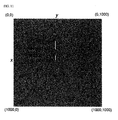
FIG. 4 is a view showing settings of a cross-sectional area of a pseudo electrode according to an exemplary embodiment of the present invention,FIG. 5 is a view showing an arrangement of the pseudo electrode according to the exemplary embodiment of the present invention, andFIG. 6 shows unipolar electrograms according to the exemplary embodiment of the present invention. - In the exemplary embodiment of the present invention, when the electrode contact state of the pseudo electrode is good, the cross-sectional area of the pseudo electrode is set to 2 mm, and a length of the
first electrode 21 and a length of thesecond electrode 22 are set to 2 mm and 3.5 mm, respectively. An area of the heart for generating the pseudo electrogram using the pseudo electrode is 25×25 (cm2), an area of a unit cell is 0.25×0.25 (mm2), and thus 1000×1000 unit cells may be distributed. - Referring to
FIG. 5 , when one corner of thefirst electrode 21 is located at a point (500, 500) and a tip electrode of the pseudo electrode is located thereover, a unipolar electrogram of thefirst electrode 21 may be calculated according to
second electrode 22 may be calculated according to
electrogram generation unit 11. - As shown in
FIG. 6 , the unipolar electrograms may be generated through the above-described process. -
FIG. 7 is a view showing settings of a cross-sectional area of a pseudo electrode according to another exemplary embodiment of the present invention,FIG. 8 is a view showing an arrangement of the pseudo electrode according to the exemplary embodiment of the present invention, andFIG. 9 shows unipolar electrograms according to the exemplary embodiment of the present invention. - In the exemplary embodiment of the present invention, when the electrode contact state of the pseudo electrode is generally good, the cross-sectional area of the pseudo electrode is set to 1 mm, and a length of the
first electrode 21 and a length of thesecond electrode 22 are set to 2 mm and 3.5 mm, respectively. An area of the heart for generating the pseudo electrogram using the pseudo electrode is 25×25 (cm2), an area of the unit cell is 0.25×0.25 (mm2), and thus 1000×1000 unit cells may be distributed. - Referring to
FIG. 8 , when one corner of thefirst electrode 21 is located at a point (500, 500) and a tip electrode of the pseudo electrode is located thereover, a unipolar electrogram of thefirst electrode 21 may be calculated according to
second electrode 22 may be calculated according to
electrogram generation unit 11. - As shown in
FIG. 9 , the unipolar electrograms may be generated through the above-described process. -
FIG. 10 is a view showing settings of a cross-sectional area of a pseudo electrode according to still another exemplary embodiment of the present invention,FIG. 11 is a view showing an arrangement of the pseudo electrode according to the exemplary embodiment of the present invention, andFIG. 12 shows unipolar electrograms according to the exemplary embodiment of the present invention. - In the exemplary embodiment of the present invention, when the electrode contact state of the pseudo electrode is not good, the cross-sectional area of the pseudo electrode is set to 0.25 mm, and a length of the
first electrode 21 and a length of thesecond electrode 22 are set to 2 mm and 3.5 mm, respectively. An area of the heart for generating the pseudo electrogram using the pseudo electrode is 25×25 (cm2), an area of the unit cell is 0.25×0.25 (mm2), and thus 1000×1000 unit cells may be distributed. - Referring to
FIG. 11 , when one corner of thefirst electrode 21 is located at a point (500, 500) and a tip electrode of the pseudo electrode is located thereover, a unipolar electrogram of thefirst electrode 21 may be calculated according to
second electrode 22 may be calculated according to
electrogram generation unit 11. - As shown in
FIG. 12 , the unipolar electrograms may be generated through the above-described process. - The pseudo
electrogram generation unit 12 may calculate the pseudo electrogram using a difference between the unipolar electrogram of thefirst electrode 21 and the unipolar electrogram of thesecond electrode 22. - An example of the process of generating the pseudo electrogram will be described using the unipolar electrograms generated through the processes shown in
FIGS. 4 to 12 . -
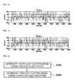
FIG. 13 is a pseudo electrogram generated according to an exemplary embodiment of the present invention. According to the exemplary embodiment of the present invention, the pseudoelectrogram generation unit 12 may calculate the pseudo electrogram using Equation (2) through a difference between a first unipolar electrogram and a second unipolar electrogram which are calculated when an electrode contact state of the pseudo electrode is good.
-
FIG. 14 is a pseudo electrogram generated according to another exemplary embodiment of the present invention. According to the exemplary embodiment of the present invention, the pseudoelectrogram generation unit 12 may calculate the pseudo electrogram using Equation (3) through a difference between a first unipolar electrogram and a second unipolar electrogram which are calculated when an electrode contact state of the pseudo electrode is generally good.
-
FIG. 15 is a pseudo electrogram generated according to still another exemplary embodiment of the present invention. According to the exemplary embodiment of the present invention, the pseudoelectrogram generation unit 12 may calculate the pseudo electrogram using Equation (4) through a difference between a first unipolar electrogram and a second unipolar electrogram which are calculated when an electrode contact state of the pseudo electrode is not good.
- The
filtering unit 13 may filter only signals in a predetermined frequency range from the pseudo electrogram and output the signals. For example, thefiltering unit 13 may filter only signals in a frequency range of 30 Hz to 500 Hz and output the signals, preferably may filter only signals in a frequency range of 30 Hz to 300 Hz and output the signals. -
FIG. 16 is a flowchart of a method for generating a pseudo electrogram according to an exemplary embodiment of the present invention. - A unipolar electrogram is generated using an action potential calculated from the electric physiological model of the heart using a pseudo electrode in which a cross-sectional area is adjusted. The unipolar electrogram may be calculated by the following equation, and unipolar electrograms corresponding to the
first electrode 21 and thesecond electrode 22 of the pseudo electrode, respectively, may be calculated (S1601).
(S1: a cross-sectional area of an electrode, S2: a cross-sectional area of a unit cell, x0: a location of a tip of a pseudo electrode on an x-axis, k: the number of cells occupied by the electrode on the x-axis, y0: a location of a tip of a pseudo electrode on a y-axis, 1: the number of cells occupied by the electrode on the y-axis, V: an action potential) - A pseudo electrogram may be generated using a difference between the unipolar electrogram of the
first electrode 21 and the unipolar electrogram of the second electrode 22 (S1602). - According to the system and method for generating the pseudo electrogram according to the exemplary embodiments of the present invention, an electrogram for inducing a complex fractionated atrial electrogram can be non-invasively generated using a pseudo electrode. Further, a pseudo electrogram generated using the pseudo electrode can be used for providing location data for performing radiofrequency catheter ablation, predicting electrical physiological activities found in the heart of a patient during surgery, and then predicting and diagnosing a result of the prediction.
- Here, the term "unit" refers to software or a hardware component such as a field programmable gate array (FPGA) or an application specific integrated circuit (ASIC), which can perform certain functions. However, the unit is not limited to software or hardware. The unit may be configured in a recording medium which can be addressed or may be configured to execute at least one processor. Examples of the unit may include software components, object-oriented software components, class components, components such as task components, processes, functions, properties, procedures, subroutines, segments in program codes, drivers, firmware, microcode, circuits, data, databases, data structures, tables, arrays, and variables. Components and functions provided from units may be combined into a smaller number of components and units or may be separated into additional components and units. In addition, the components and units may execute at least one CPU in a device.
- While the present invention has been described with reference to the exemplary embodiments, it should be understood by those skilled in the art that various changes and modifications may be made herein without departing from the scope of the present invention as defined by the appended claims.
Claims (9)
- A system for generating a pseudo electrogram, comprising:a unipolar electrogram generation unit configured to generate a unipolar electrogram according to an action potential calculated from an electric physiological model of the heart using a pseudo electrode in which a cross-sectional area is adjusted; anda pseudo electrogram generation unit configured to generate a pseudo electrogram using the unipolar electrogram.
- The system of claim 1, wherein the pseudo electrode comprises a first electrode and a second electrode.
- The system of claim 2, wherein the unipolar electrogram generation unit generates the unipolar electrogram according to the following equation.

(S1: a cross-sectional area of an electrode, S2: a cross-sectional area of a unit cell, x0: a location of a tip of a pseudo electrode on an x-axis, k: the number of cells occupied by the electrode on the x-axis, y0: a location of a tip of a pseudo electrode on a y-axis, 1: the number of cells occupied by the electrode on the y-axis, V: an action potential) - The system of claim 3, wherein the pseudo electrogram generation unit calculates the pseudo electrogram using a difference between a unipolar electrogram of the first electrode and a unipolar electrogram of the second electrode.
- The system of claim 1, further comprising a filtering unit configured to filter only a signal in a predetermined frequency range from the pseudo electrogram.
- The system of claim 1, wherein the filtering unit filters only a signal in a frequency range of 30 Hz to 300 Hz.
- A method of generating a pseudo electrogram, comprising:generating a unipolar electrogram according to an action potential calculated from an electric physiological model of the heart using a pseudo electrode in which a cross-sectional area is adjusted; andgenerating a pseudo electrogram using the unipolar electrogram.
- The method of claim 7, wherein the generating of the unipolar electrogram generates the unipolar electrogram according to the following equation.

(S1: a cross-sectional area of an electrode, S2: a cross-sectional area of a unit cell, x0: a location of a tip of a pseudo electrode on an x-axis, k: the number of cells occupied by the electrode on the x-axis, y0: a location of a tip of a pseudo electrode on a y-axis, 1: the number of cells occupied by the electrode on the y-axis, V: an action potential) - The method of claim 8, wherein the generating of the pseudo electrogram calculates the pseudo electrogram using a difference between a unipolar electrogram of a first electrode and a unipolar electrogram of a second electrode.
Applications Claiming Priority (2)
| Application Number | Priority Date | Filing Date | Title |
|---|---|---|---|
| KR1020120099076A KR101432368B1 (en) | 2012-09-07 | 2012-09-07 | System and method for generating pseudo electrogram |
| PCT/KR2013/008057 WO2014038883A1 (en) | 2012-09-07 | 2013-09-06 | System and method for generating simulated electrogram |
Publications (2)
| Publication Number | Publication Date |
|---|---|
| EP2893954A1 true EP2893954A1 (en) | 2015-07-15 |
| EP2893954A4 EP2893954A4 (en) | 2016-06-01 |
Family
ID=50237416
Family Applications (1)
| Application Number | Title | Priority Date | Filing Date |
|---|---|---|---|
| EP13834431.2A Withdrawn EP2893954A4 (en) | 2012-09-07 | 2013-09-06 | SYSTEM AND METHOD FOR SIMULATED ELECTROGRAM GENERATION |
Country Status (4)
| Country | Link |
|---|---|
| US (1) | US10360281B2 (en) |
| EP (1) | EP2893954A4 (en) |
| KR (1) | KR101432368B1 (en) |
| WO (1) | WO2014038883A1 (en) |
Families Citing this family (1)
| Publication number | Priority date | Publication date | Assignee | Title |
|---|---|---|---|---|
| WO2015153832A1 (en) | 2014-04-02 | 2015-10-08 | Siemens Aktiengesellschaft | System and method for characterization of electrical properties of the heart from medical images and body surface potentials |
Family Cites Families (12)
| Publication number | Priority date | Publication date | Assignee | Title |
|---|---|---|---|---|
| US4585004A (en) * | 1984-06-01 | 1986-04-29 | Cardiac Control Systems, Inc. | Heart pacing and intracardiac electrogram monitoring system and associated method |
| US5111816A (en) * | 1989-05-23 | 1992-05-12 | Ventritex | System configuration for combined defibrillator/pacemaker |
| US5692907A (en) | 1995-08-16 | 1997-12-02 | Pacesetter, Inc. | Interactive cardiac rhythm simulator |
| WO1999006112A1 (en) * | 1997-07-31 | 1999-02-11 | Case Western Reserve University | Electrolphysiological cardiac mapping system based on a non-contact non-expandable miniature multi-electrode catheter and method therefor |
| US20050202384A1 (en) | 2001-04-20 | 2005-09-15 | Medtronic, Inc. | Interactive computer model of the heart |
| US9629567B2 (en) * | 2006-01-12 | 2017-04-25 | Biosense Webster, Inc. | Mapping of complex fractionated atrial electrogram |
| US7751873B2 (en) * | 2006-11-08 | 2010-07-06 | Biotronik Crm Patent Ag | Wavelet based feature extraction and dimension reduction for the classification of human cardiac electrogram depolarization waveforms |
| US8359092B2 (en) * | 2007-11-29 | 2013-01-22 | Biosense Webster, Inc. | Determining locations of ganglia and plexi in the heart using complex fractionated atrial electrogram |
| AU2009302220B2 (en) * | 2008-10-09 | 2014-03-27 | The Regents Of The University Of California | Methods, system and apparatus for the detection, diagnosis and treatment of biological rhythm disorders |
| US8718750B2 (en) * | 2011-05-26 | 2014-05-06 | Biotronik Se & Co. Kg | Heart stimulator and method for A-V delay optimization |
| AU2012312066C1 (en) * | 2011-09-22 | 2016-06-16 | 460Medical, Inc. | Systems and methods for visualizing ablated tissue |
| WO2016183247A1 (en) * | 2015-05-12 | 2016-11-17 | St. Jude Medical, Cardiology Division, Inc. | Systems and methods for orientation independent sensing |
-
2012
- 2012-09-07 KR KR1020120099076A patent/KR101432368B1/en active Active
-
2013
- 2013-09-06 WO PCT/KR2013/008057 patent/WO2014038883A1/en not_active Ceased
- 2013-09-06 EP EP13834431.2A patent/EP2893954A4/en not_active Withdrawn
- 2013-09-06 US US14/426,400 patent/US10360281B2/en active Active
Also Published As
| Publication number | Publication date |
|---|---|
| EP2893954A4 (en) | 2016-06-01 |
| US10360281B2 (en) | 2019-07-23 |
| KR20140032625A (en) | 2014-03-17 |
| US20150242587A1 (en) | 2015-08-27 |
| KR101432368B1 (en) | 2014-08-20 |
| WO2014038883A1 (en) | 2014-03-13 |
Similar Documents
| Publication | Publication Date | Title |
|---|---|---|
| US20250318954A1 (en) | Systems and methods for ocular laser surgery and therapeutic treatments | |
| Office of the Surgeon General (US | Bone health and osteoporosis: a report of the surgeon general | |
| CN104840197B (en) | Machine and process for the source for being automatically positioned biological rhythm disorder | |
| JP2022531658A (en) | Systems and methods for noise reduction of physiological signals during electrical neural regulation | |
| US20110301586A2 (en) | Apparatus and Methods for Arrhythmia Treatment Based on Spectral Mapping During Sinus Rhythm | |
| US20170221262A1 (en) | Medical devices for mapping cardiac tissue and methods for displaying mapping data | |
| US20150250399A1 (en) | Medical devices for mapping cardiac tissue | |
| WO2021129027A1 (en) | Ablation system and nerve detection device therefor | |
| US9968783B2 (en) | Treatment for cardiac conductance abnormalities | |
| US20260114919A1 (en) | Systems and methods of denervation around subclavian arteries | |
| EP3409191B1 (en) | Cardiac electrophysiology machine including catheter stability while estimating impedance drop | |
| KR101443156B1 (en) | Apparatus for virtual catherter ablation of arrhythmias | |
| US20190298213A1 (en) | Method and system for predicting heart tissue activation | |
| US10360281B2 (en) | System and method for generating pseudo electrogram | |
| JP6900297B2 (en) | Defibrillation system | |
| CN118647328A (en) | EGM frequency analysis for damage assessment | |
| Joshi | Perioperative management of outpatients with implantable cardioverter defibrillators | |
| Rockswold et al. | Hypoxia and traumatic brain injury | |
| Deda et al. | Anteromedial approach to the orbit | |
| Pongratz et al. | Catheter Ablation in Complex Atrial Arrhythmias: Pilot Study Evaluating a 3D Wide-Band Dielectric Imaging System | |
| Daly et al. | The AF-FICIENT magnetic resonance imaging and endoscopy safety substudy: A visually guided radiofrequency balloon ablation catheter for pulmonary vein isolation | |
| RU2387364C2 (en) | Method of evaluating efficiency of left auricle posterior wall isolation | |
| Usurelu et al. | De Winter syndrome–clinical case | |
| Blackshear et al. | Immediate and Long-term Prevention of Thromboembolism in Atrial Fibrillation (AF) | |
| Reumann et al. | Simulating pulmonary vein activity leading to atrial fibrillation using a rule-based approach on realistic anatomical data |
Legal Events
| Date | Code | Title | Description |
|---|---|---|---|
| PUAI | Public reference made under article 153(3) epc to a published international application that has entered the european phase |
Free format text: ORIGINAL CODE: 0009012 |
|
| 17P | Request for examination filed |
Effective date: 20150405 |
|
| AK | Designated contracting states |
Kind code of ref document: A1 Designated state(s): AL AT BE BG CH CY CZ DE DK EE ES FI FR GB GR HR HU IE IS IT LI LT LU LV MC MK MT NL NO PL PT RO RS SE SI SK SM TR |
|
| AX | Request for extension of the european patent |
Extension state: BA ME |
|
| DAX | Request for extension of the european patent (deleted) | ||
| RA4 | Supplementary search report drawn up and despatched (corrected) |
Effective date: 20160504 |
|
| RIC1 | Information provided on ipc code assigned before grant |
Ipc: G06F 17/11 20060101ALI20160428BHEP Ipc: G06F 19/00 20110101ALI20160428BHEP Ipc: A61B 5/00 20060101ALI20160428BHEP Ipc: A61B 5/0402 20060101ALI20160428BHEP Ipc: A61N 1/365 20060101AFI20160428BHEP |
|
| STAA | Information on the status of an ep patent application or granted ep patent |
Free format text: STATUS: THE APPLICATION HAS BEEN WITHDRAWN |
|
| 18W | Application withdrawn |
Effective date: 20181001 |