EP2893390B1 - Pixel mapping, arranging, and imaging for round and square-based micro lens arrays to achieve full volume 3d and multi-directional motion - Google Patents
Pixel mapping, arranging, and imaging for round and square-based micro lens arrays to achieve full volume 3d and multi-directional motion Download PDFInfo
- Publication number
- EP2893390B1 EP2893390B1 EP13835055.8A EP13835055A EP2893390B1 EP 2893390 B1 EP2893390 B1 EP 2893390B1 EP 13835055 A EP13835055 A EP 13835055A EP 2893390 B1 EP2893390 B1 EP 2893390B1
- Authority
- EP
- European Patent Office
- Prior art keywords
- axis
- lenses
- image
- assembly
- array
- Prior art date
- Legal status (The legal status is an assumption and is not a legal conclusion. Google has not performed a legal analysis and makes no representation as to the accuracy of the status listed.)
- Revoked
Links
Images


Classifications
-
- B—PERFORMING OPERATIONS; TRANSPORTING
- B42—BOOKBINDING; ALBUMS; FILES; SPECIAL PRINTED MATTER
- B42D—BOOKS; BOOK COVERS; LOOSE LEAVES; PRINTED MATTER CHARACTERISED BY IDENTIFICATION OR SECURITY FEATURES; PRINTED MATTER OF SPECIAL FORMAT OR STYLE NOT OTHERWISE PROVIDED FOR; DEVICES FOR USE THEREWITH AND NOT OTHERWISE PROVIDED FOR; MOVABLE-STRIP WRITING OR READING APPARATUS
- B42D25/00—Information-bearing cards or sheet-like structures characterised by identification or security features; Manufacture thereof
- B42D25/30—Identification or security features, e.g. for preventing forgery
-
- B—PERFORMING OPERATIONS; TRANSPORTING
- B41—PRINTING; LINING MACHINES; TYPEWRITERS; STAMPS
- B41J—TYPEWRITERS; SELECTIVE PRINTING MECHANISMS, i.e. MECHANISMS PRINTING OTHERWISE THAN FROM A FORME; CORRECTION OF TYPOGRAPHICAL ERRORS
- B41J2/00—Typewriters or selective printing mechanisms characterised by the printing or marking process for which they are designed
-
- B—PERFORMING OPERATIONS; TRANSPORTING
- B41—PRINTING; LINING MACHINES; TYPEWRITERS; STAMPS
- B41M—PRINTING, DUPLICATING, MARKING, OR COPYING PROCESSES; COLOUR PRINTING
- B41M3/00—Printing processes to produce particular kinds of printed work, e.g. patterns
- B41M3/14—Security printing
-
- B—PERFORMING OPERATIONS; TRANSPORTING
- B42—BOOKBINDING; ALBUMS; FILES; SPECIAL PRINTED MATTER
- B42D—BOOKS; BOOK COVERS; LOOSE LEAVES; PRINTED MATTER CHARACTERISED BY IDENTIFICATION OR SECURITY FEATURES; PRINTED MATTER OF SPECIAL FORMAT OR STYLE NOT OTHERWISE PROVIDED FOR; DEVICES FOR USE THEREWITH AND NOT OTHERWISE PROVIDED FOR; MOVABLE-STRIP WRITING OR READING APPARATUS
- B42D15/00—Printed matter of special format or style not otherwise provided for
-
- B—PERFORMING OPERATIONS; TRANSPORTING
- B42—BOOKBINDING; ALBUMS; FILES; SPECIAL PRINTED MATTER
- B42D—BOOKS; BOOK COVERS; LOOSE LEAVES; PRINTED MATTER CHARACTERISED BY IDENTIFICATION OR SECURITY FEATURES; PRINTED MATTER OF SPECIAL FORMAT OR STYLE NOT OTHERWISE PROVIDED FOR; DEVICES FOR USE THEREWITH AND NOT OTHERWISE PROVIDED FOR; MOVABLE-STRIP WRITING OR READING APPARATUS
- B42D25/00—Information-bearing cards or sheet-like structures characterised by identification or security features; Manufacture thereof
- B42D25/30—Identification or security features, e.g. for preventing forgery
- B42D25/324—Reliefs
-
- B—PERFORMING OPERATIONS; TRANSPORTING
- B42—BOOKBINDING; ALBUMS; FILES; SPECIAL PRINTED MATTER
- B42D—BOOKS; BOOK COVERS; LOOSE LEAVES; PRINTED MATTER CHARACTERISED BY IDENTIFICATION OR SECURITY FEATURES; PRINTED MATTER OF SPECIAL FORMAT OR STYLE NOT OTHERWISE PROVIDED FOR; DEVICES FOR USE THEREWITH AND NOT OTHERWISE PROVIDED FOR; MOVABLE-STRIP WRITING OR READING APPARATUS
- B42D25/00—Information-bearing cards or sheet-like structures characterised by identification or security features; Manufacture thereof
- B42D25/30—Identification or security features, e.g. for preventing forgery
- B42D25/342—Moiré effects
-
- B—PERFORMING OPERATIONS; TRANSPORTING
- B44—DECORATIVE ARTS
- B44F—SPECIAL DESIGNS OR PICTURES
- B44F1/00—Designs or pictures characterised by special or unusual light effects
- B44F1/08—Designs or pictures characterised by special or unusual light effects characterised by colour effects
- B44F1/10—Changing, amusing, or secret pictures
-
- G—PHYSICS
- G02—OPTICS
- G02B—OPTICAL ELEMENTS, SYSTEMS OR APPARATUS
- G02B30/00—Optical systems or apparatus for producing three-dimensional [3D] effects, e.g. stereoscopic images
- G02B30/20—Optical systems or apparatus for producing three-dimensional [3D] effects, e.g. stereoscopic images by providing first and second parallax images to an observer's left and right eyes
- G02B30/26—Optical systems or apparatus for producing three-dimensional [3D] effects, e.g. stereoscopic images by providing first and second parallax images to an observer's left and right eyes of the autostereoscopic type
- G02B30/27—Optical systems or apparatus for producing three-dimensional [3D] effects, e.g. stereoscopic images by providing first and second parallax images to an observer's left and right eyes of the autostereoscopic type involving lenticular arrays
-
- G—PHYSICS
- G06—COMPUTING; CALCULATING OR COUNTING
- G06F—ELECTRIC DIGITAL DATA PROCESSING
- G06F3/00—Input arrangements for transferring data to be processed into a form capable of being handled by the computer; Output arrangements for transferring data from processing unit to output unit, e.g. interface arrangements
- G06F3/12—Digital output to print unit, e.g. line printer, chain printer
-
- G—PHYSICS
- G09—EDUCATION; CRYPTOGRAPHY; DISPLAY; ADVERTISING; SEALS
- G09F—DISPLAYING; ADVERTISING; SIGNS; LABELS OR NAME-PLATES; SEALS
- G09F19/00—Advertising or display means not otherwise provided for
- G09F19/12—Advertising or display means not otherwise provided for using special optical effects
- G09F19/14—Advertising or display means not otherwise provided for using special optical effects displaying different signs depending upon the view-point of the observer
Definitions
- the present invention relates, in general, to combining printed images with lens arrays to display three dimensional (3D) images with or without motion, and, more particularly, to a method of pixel mapping, providing arrangements of pixels, and imaging that is adapted for use with arrays of square or round-based micro lenses to provide enhanced 3D imagery with fuller volume and/or with multi-directional motion.
- anti-counterfeiting efforts often involve use of an anti-counterfeiting device or element that is made up of an array of lenses and an image printed onto the back of the lens array or onto an underlying substrate or surface (e.g., a sheet of paper or plastic).
- the anti-counterfeiting element may be used to display an image that is chosen to be unique and be an indicator that the item carrying the anti-counterfeiting element is not a counterfeit.
- anti-counterfeiting market is rapidly growing worldwide with anti-counterfeiting elements placed on a wide range of items such as upon currency (e.g., on a surface of a paper bill to help prevent copying) and on labels for retail products (e.g., labels on clothing showing authenticity).
- currency e.g., on a surface of a paper bill to help prevent copying
- labels for retail products e.g., labels on clothing showing authenticity
- moire patterns have been used for years in anti-counterfeiting elements with arrays of round lenses and with arrays of hexagonal arrays (or round and hexagonal lens arrays).
- the printed images provided in an ink layer under these lens arrays are small, fine images relative to the size of the lenses.
- a moire pattern is provided in the printed images in the form of a secondary and visually evident superimposed pattern that is created when two identical patterns on a surface are overlaid while being displaced or rotated a small amount from each other.
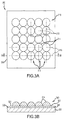
- FIG. 1 illustrates an exemplary assembly 100 that may be used as an anti-counterfeiting element.
- the assembly 100 includes a lens array 110 made up of side-by-side, parallel columns (or rows) 112 of round lenses 114, and it can be seen that the columns 112 are offset from each other (by about 50 percent) such that pairs of adjacent lenses 114 in the columns are not aligned (e.g., a lens in a next column is positioned in the space between two lenses in the previous column).
- a printed image 120 is provided in a layer of ink underneath the lens array 110 (on a back, planar surface of the lens array 110).
- the result which is difficult to see in Figure 1 , is a moire pattern that provides the illusion of depth of field to a viewer via the lenses 112 of the array 110 or, in some cases, the sense that the images are moving (motion or animation of the displayed items).
- the thickness of each of the lenses 112 is in the range of 0.5/1000 to 5/1000 inches (or 12 to about 125 microns), and the frequency of these lenses 112 in an array 110 is about 400 X 400 to over 1000 X 1000 per inch.
- moire patterns While helpful to reduce counterfeiting, use of moire patterns with round lens arrays has not been wholly satisfactory for the anti-counterfeiting market.
- One reason is that the effects that can be achieved with moire patterns are limited. For example, one cannot take a photograph and display 3D with a moire pattern.
- the moire patterns are used in the security and/or anti-counterfeiting industry in very fine lenses with focal lengths of about 20 to 75 microns and frequencies of over 500 lenses per inch in one axis or more than 250,000 lenses per square inch.
- the images underlying the lenses in the lens array are typically printed at least at 12,000 DPI (dots per inch) and may even be provided at over 25,000 DPI.
- micro-lens arrays are generally closely nested as shown in element 200 with its array 210 in Figure 2 .
- the array 210 uses hexagonal lenses that are provided in offset and overlapping columns 212 (e.g., side-by-side lenses 214 are not aligned in a row and are positioned to fill or be nested into space between two lenses of adjacent columns 212) to focus on an image or moire pattern 220 in an underlying ink layer.
- the element 200 is relatively easy to reverse engineer, which limits its usefulness as an anti-counterfeiting element.
- the patterns 220 underlying the lenses 214 can be seen with an inexpensive and readily available microscope, which allows one to determine the frequency of the images and patterns.
- the lenses 214 can be cast and re-molded, which leaves printing the identified images as the only hurdle for successfully copying the element 200 (and then counterfeiting a piece of currency or a label for a product).
- printing the image 220 is becoming easier to accomplish due to high resolution lasers and setters and other printing advances.
- the micro-lenses are printed using an emboss and fill technology, which limits the printing to one color due to the fact that the process tends to be self-contaminating after one color and also due to the fact that the process is difficult to control from a relative color-to-color pitch in the emboss-and-fill printing process.
- the invention provides for an assembly according to claim 1 ans a method according to claim 10.
- the inventors recognized that it may be beneficial to provide a different nesting of lenses in an array that can then be combined with an image having dual-axis interlacing.
- the lenses may be circular or square-based lenses that have their centers aligned such that the array is made up of parallel rows and columns of lenses (e.g., without having adjacent lenses being offset from each other as seen in the arrays of Figures 1 and 2 ).
- the image is printed from a print file generated from a matrix of frames of images taken from a plurality of points of view (POVs) along both a first axis (X axis) and also along a second axis (Y axis).
- the frames are interlaced in both directions to provide a pixel mapping to the lenses of the array.
- a visual display assembly that is useful as an anti-counterfeiting device on paper currency, product labels, and other objects.
- the assembly includes a film of transparent material including a first surface including an array of lenses and a second surface opposite the first surface.
- the assembly also includes a printed image proximate to the second surface.
- the printed image includes pixels of frames of one or more images interlaced relative to two orthogonal axes (printed from a file generated using dual-axis interlacing rather than single axis interlacing as in conventional lenticular printing).
- the lenses of the array are nested in a plurality of parallel rows, and adjacent ones of the lenses in columns of the array are aligned to be in a single one of the rows (e.g., no offsetting of adjacent lenses).
- the lenses may be round-based lenses or are square-based lenses.
- the lenses of the array are provided at 200 LPI (or a higher LPI) as measured along both of the two orthogonal axes.
- the lenses may each have a focal length of less than 10/1000 inches.
- the frames each include a different point of view (POV) of the one or more images.
- the frames include images from at least three POVs along a first of the two orthogonal axes, and the frames further include images from at least two additional POVs corresponding to each of the three POVs along the second of the two orthogonal axes.
- the printed image may be adapted such that an image displayed from a normal POV includes a first set of symbols and a second set of symbols, and, in an image displayed when the assembly is rotated from the normal POV about a first axis, the first and second sets of symbols move in opposite directions. Further, the printed image may be adapted such that in an image displayed, when the assembly is rotated from the normal POV about a second axis orthogonal to the first axis, the first and second symbols move in a single direction that is orthogonal to the second axis.
- the printed image can be adapted such that an image displayed from a normal POV includes a first set of symbols and a second set of symbols, and, in an image displayed when the assembly is rotated from the normal POV about a first axis, the first and second sets of symbols can move in a single direction that is parallel to the first axis of the assembly.
- the printed image is adapted such that in an image displayed when the assembly is rotated from the normal POV about a second axis orthogonal to the first axis, the first and second symbols move in a single direction that is parallel to the second axis.
- the printed image may include a wallpaper pattern (e.g., with icons, logos, and other symbols) and an overlay pattern.
- the printed image may include mapped pixels such that the wallpaper pattern is visible from a plurality of POVs (when the assembly is rotated/tilted to differing angles relative to a viewer's line of sight), and the overlay pattern has a range of differing visibilities over the plurality of POVs.
- the differing visibilities may include the overlay being invisible (or only faintly visible) to a viewer along a normal POV of the assembly while rotating or tilting the assembly away further and further from normal (in any direction in some cases) causes the darkness or brightness of the overlay pattern to increase until it is fully visible (or as dark or bright in color as it can be such as at some more extreme angle relative to normal such as an angle in the range of 45 to 60 degrees or the like).
- the present description is directed toward designs for assemblies of lens arrays combined with printed images provided in an ink layer.
- the assemblies can be used, for example but not as a limitation, as anti-counterfeiting elements or devices.
- the lens arrays differ from those shown in Figures 1 and 2 , in part, because the lenses are arranged in columns that are not vertically offset such that the lenses are provided in parallel columns and also in parallel rows (e.g., pairs of adjacent lenses in side-by-side columns are aligned with their center axes being collinear).
- the lenses may be round or square-based, and the underlying image has its pixels mapped and arranged such that the micro lens arrays produce a 3D displayed image with full volume and, in some cases, with multi-directional motion or animation.
- an item 300 (such as a piece of paper currency, a label for a product, or the like) is provided with an anti-counterfeiting element or device in the form of a lens array (round lens array) 310 covering or provided on top of a layer of ink 320 providing a printed image.
- the item 300 includes a substrate or body 305 such as a sheet of paper or plastic (e.g., paper to be used as currency or paper/plastic to be used for a product label).
- an image is printed via a layer of ink 320, and a lens array 310 is provided on an exposed surface of the ink layer 320 (e.g., the ink layer 317 and its pattern/image may be printed onto the substrate surface 307 or onto the back surface of the lens array 310).
- a lens array 310 is provided on an exposed surface of the ink layer 320 (e.g., the ink layer 317 and its pattern/image may be printed onto the substrate surface 307 or onto the back surface of the lens array 310).
- the lens array 310 is made up of a plurality of lenses 314 that each have a round base 317 abutting the surface 321 of the ink layer 320 and have a dome-shaped cross section as seen in Figure 3B .
- the round-based lenses or round lenses 314 are arranged in a number of columns 312 that are parallel as shown by parallel vertical or Y-axes 313 (axes passing through the center of the lenses 314 in columns 312) in Figure 3A .
- the lenses 314 are arranged such that pairs of lenses 314 in adjacent ones of the columns 312 are in contact or proximate at least at the bases 317 (as seen in Figures 3A and 3B ).
- the columns 312 are not vertically offset as seen in arrays 110, 210 of Figures 1 and 2 such that pairs of adjacent lenses 314 are aligned in rows as can be seen by parallel horizontal or X-axes 315 passing through centers of lenses 314 in the array 310 (e.g., the lenses 314 of the array 310 are both vertically and horizontally aligned due to the specific nesting shown in Figure 3A ).
- an item 400 (such as a piece of paper currency, a label for a product, or the like) is provided with an anti-counterfeiting element or device in the form of a lens array (round lens array) 410 covering or provided on top of a layer of ink 420 providing a printed image.
- the item 400 includes a substrate or body 405 such as a sheet of paper or plastic (e.g., paper to be used as currency or paper/plastic to be used for a product label).
- an image is printed via a layer of ink 420, and a lens array 410 is provided on an exposed surface of the ink layer 420 (e.g., the ink layer 417 and its pattern/image may be printed onto the substrate surface 407 or onto the back surface of the lens array 410).
- a lens array 410 is provided on an exposed surface of the ink layer 420 (e.g., the ink layer 417 and its pattern/image may be printed onto the substrate surface 407 or onto the back surface of the lens array 410).
- the lens array 410 is made up of a plurality of lenses 414 that each have a square base 417 abutting the surface 421 of the ink layer 420 and may have a dome-shaped cross section as seen in Figure 4B .
- the square-based lenses or square lenses 414 are arranged in a number of columns 412 that are parallel as shown by parallel vertical or Y-axes 413 (axes passing through the center of the lenses 414 in columns 412) in Figure 4A . Further, the lenses 414 are arranged such that pairs of lenses 414 in adjacent ones of the columns 412 are in contact or proximate at least at the bases 417 (as seen in Figures 4A and 4B ).
- the columns 412 are not vertically offset as seen in arrays 110, 210 of Figures 1 and 2 such that pairs of adjacent lenses 414 are aligned in rows as can be seen by parallel horizontal or X-axes 415 passing through centers of lenses 414 in the array 410 (e.g., the lenses 414 of the array 410 are both vertically and horizontally aligned due to the illustrated nesting of the lenses 414).
- the lenses may be provided at a frequency of as few as 150 lenses per linear inch in both the X and Y axes or up to about 4000 lenses per linear inch on each of the X and Y axes.
- the lenses are nested as shown in Figures 3A and 4A so that there is little or no interference from the adjoining or adjacent lenses when an image in ink layers 320, 420 are viewed by a viewer of the items 300, 400.
- Both stacked square-based and round-based lenses 414, 314 may be used to support the interfacing process described herein for providing the image/pattern in ink layer 320, 420. In some cases, the square-based lenses 314 may be preferred as these produce a fuller or full-filled image.
- the ink layers 320, 420 are adapted or designed for use with the lens arrays 310, 410 to provide full volume 3D displayed images with or without multi-directional motion or animation. Particularly, images are interlaced, similar to lenticular images, in the X-axis and also then in the Y-axis to create full volume 3D interlaced images.
- the lenses 314, 414 have a point focus for a viewer, and the resulting image (displayed image from light reflected from the ink layers 320, 420 via the lens arrays 310, 410) to the viewer is a 3D image in all directions, regardless of the viewpoint.
- lens arrays With a general understanding of the lens arrays and their configurations understood, it may be useful to discuss pixel arrangement, imaging, and mapping for circular-based and square-based lenses (e.g., design of the ink layers of the assemblies shown in Figures 3A-4B ).
- Traditional lenticular printing (interlaced printing of images for use with lenticular lens arrays) uses a certain number of files that are created from different points of view (or viewpoints) in order to get a 3D effect. For example, a point of view in a single plane is moved to the left or to the right to create a next point of view.
- Traditional lenticular printing also uses different frames from a sequence of images to create some motion or animation or other visual effects.
- interlacing e.g., the process of striping and arranging printed information to a given pitch to match a particular lenticular lens array.
- FIG. 5 illustrates a process 500 in which a set of files of a single image or scene 540 viewed from three different viewpoints 510, 520, and 530 (such as -45 degrees, orthogonal, and +45 degrees or the like) are obtained for use in printing.
- the viewpoints 510, 520, and 530 are views from the same scene taken along the horizontal or X-axis.
- the frames or viewpoints 510, 520, 530 resulting from the points of views are slightly different and are then combined in an interlacing process.
- this frame of interlaced images is combined with a sheet of lenticular material and viewed, the frame can generate depth perception or a 3D effect.
- circular and square-based lenses may be used in a lens array with a printed image, and these lenses allow the effects to work in two directions concurrently, e.g., in the horizontal and vertical directions at the same time.
- the fact that the visual effects are created in all directions also demands that a more complete set of frames or views from the same scene be provided in the printed image (or ink layer) used with round or square lens arrays.
- the inventors developed a new process (described below) for interlacing (or, more accurately, mapping, arranging, and imaging pixels) these sets of frames from a single scene.
- FIG. 6 shows a process 600 for obtaining additional frames or views from the scene 640 (which may be the same as scene/image 540).
- frames 610, 620, 630 from three different viewpoints e.g., +45 degrees relative to orthogonal to the Y-axis, orthogonal to the Y-axis, and -45 degrees relative to the Y-axis or the like
- viewpoints e.g., +45 degrees relative to orthogonal to the Y-axis, orthogonal to the Y-axis, and -45 degrees relative to the Y-axis or the like
- Figures 5-7 provide a simple example, but many other numbers of points of view may be utilized.
- a traditional lenticular printing may involve sue of 10 frames corresponding with 10 different view points along the X-axis (or Y-axis).
- the presently described interlacing or image printing process would involve 10 sets of ten frames each so that the total number of frames provides a matrix of 100 frames.
- the interlacing or printing process then involves mapping and imaging each of the 100 frames in individual pixels.
- the matrix of frame files (e.g., the matrix 700 of frame files of Figure 7 ) is preferably combined in order to generate the file to print and that, when printed and used with a predefined/particular lens array, can generate a desired visual effect.
- the matrix of frames would be (with the frame number providing the set number and the frame within that set): Frame 11 Frame 12 Frame 13 Frame 14 Frame 15 Frame 16 Frame 21 Frame 22 Frame 23 Frame 24 Frame 25 Frame 26 Frame 31 Frame 32 Frame 33 Frame 34 Frame 35 Frame 36 Frame 41 Frame 42 Frame 43 Frame 44 Frame 45 Frame 46 Frame 51 Frame 52 Frame 53 Frame 54 Frame 55 Frame 56 Frame 61 Frame 62 Frame 63 Frame 64 Frame 65 Frame 66
- a first step in mapping/imaging can be to combine in each row of frames from the matrix (e.g., as if vertical lenses were being used). This way a sequence of combined pixels is produced in the X axis from the same scene but from slightly different heights or points of view (from the Y axis). For example, the combining may start by interlacing the six frames from the first row of the matrix, interlacing the six frames from the second row, and so on until there is one interlaced file for each row of the matrix of frame files (images of a scene from differing points of view).
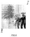
- Figure 8 illustrates an image 800 of the using the images from the matrix 700 of Figure 7 for one of the rows of the matrix.
- the resulting file providing image 800 is a combination of slices 810 from each frame in the particular row (interlaced image stripes or slices 810).
- a second step in mapping/imaging is to combine these vertically combined files (X axis) into one final file to use in printing.
- the information that is useful or even needed is one horizontal slice to concurrently or simultaneously create the effect in the other direction.
- a second mapping process (horizontal) is performed, but this time using the previously generated vertical pixel files as the input to create the bi-directional (X and Y axis) frames.
- the pixels in the files are vertically combined in the same sequence previously defined; (2) the files are regenerated with the horizontal information pursuant to the pixel map and, therefore, to create the print file; and (3) the result is a bi-directional pixel map with all of the 3D or motion information in both directions, which meant that, instead of having stripes or slices, the final file has squares with the data from the matrix arranged in a way that is similar to the frames in the matrix.
- this third item it may be important to note that when combined with the round or square-based lenses of an array, an image printed from this file will allow any viewpoint to be achieved/displayed to a viewer and will allow motion to be presented in any direction.
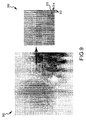
- Figure 9 illustrates an image 900 that may be printed for use with a round or square-based lens array from a final print file output from this second mapping/imaging step.
- this final linear image 900 one can see interlacing in a vertical direction with slices/stripes 912 and also in the horizontal direction with slices/stripes 914.
- the exploded and/or enlarged portion 910 is useful for showing this two-way interlacing and also for showing that the "square" composition (see, for example, square 916) of this final print file (two axis combination file).
- Mapping and imaging can also be performed using both the X axis and the Y axis to achieve a motion effect.
- the idea is to get a loop in an interlaced print image with the sequence of frames that describes or provides motion.
- This "loop" concept is also useful for the printing described herein but, again, with circular or square-based lenses, one must process a matrix of frames.
- the matrix typically should be arranged in a way that a loop sequence is viewed in each row and also in each line/column of the matrix simultaneously.
- the matrix of the 6 X 6 frames may be arranged as: Frame 5 Frame 6 Frame 1 Frame 2 Frame 3 Frame 4 Frame 6 Frame 1 Frame 2 Frame 3 Frame 4 Frame 5 Frame 1 Frame 2 Frame 3 Frame 4 Frame 5 Frame 6 Frame 2 Frame 3 Frame 4 Frame 5 Frame 6 Frame 1 Frame 3 Frame 4 Frame 5 Frame 6 Frame 1 Frame 3 Frame 4 Frame 5 Frame 6 Frame 1 Frame 2 Frame 4 Frame 5 Frame 6 Frame 1 Frame 2 Frame 3 Frame 5 Frame 6 Frame 1 Frame 2 Frame 3 Frame 5 Frame 6 Frame 1 Frame 1 Frame 2 Frame 3 Frame 5 Frame 6 Frame 1 Frame 2 Frame 3 Frame 3
- the arrangement provided in this matrix allows, when used to create a printed image, allows one to see a loop (through a circular or square-based lens array) in both directions (X and Y axis).
- the printed image also produces little to no distortion since each row and each column is slightly out of phase relative to the other nearby rows and columns.
- the interlacing process based on this matrix would then be the same as described above to obtain or produce a final interlaced file (also sometimes called an X and Y axes pixel file).
- the optical pitch of the lens should be precisely match the plate-making, proofing, or digital output device in two axes.
- the number of frames in both the X axis and the Y axis multiplied by the number of lenses should be equal (precisely equal in some cases) to the DPI (dots per inch) of the output device of the lenses' optical pitch.
- the exact lens LPI number that comes out of the construction of the sheets of lens array material is what is called mechanical pitch, but, depending on the viewing distance, those lenticules will focus on a different frequency meaning that when one combines the number of lines per inch of a certain frame there will not be a match with the number of lenticules per inch.
- a calibration process may be used (called a pitch test) to better determine the exact number of lines per inch that focus in that particular lens sheet or film at a given distance and for a particular printing device.
- the X-axis frame count multiplied by the number of lenses should be equal to the resolution of the output device (this should also hold true for the Y-axis).
- DPI generated during printing may not match the optical pitch of the printed lens. This may be due to distortion in the web or sheet process and/or due to typical shrinkage or expansion and distortion in the manufacture of a film. Even if the film is made precisely to match the optical pitch of the output device, the pitch may change significantly as the film is printed due to cylindrical distortion that is common in all printing processes (e.g., flexo, gravure, offset, letterpress, holography, emboss and fill, and the like). Also, the distortion may be greater in the repeat direction of the web or sheet around the cylinder.
- the desired optical pitch may be within some range of target (such as within 3 percent of the target).
- devices such as a VMR (Variable Main-scan Resolution) from Kodak or the like
- VMR Very Main-scan Resolution
- the pitch should be adjusted precisely using other techniques/tools so that the output device can run at the parent resolution in both axes without adversely effecting the integrity of the X and Y-axes interlaced image.
- the channels in both axes preferably stay precisely as planned in the file relative to the target optical pitch of the lens.
- the file can be "scaled" to the target number by interlacing the file in both axes at the closest whole integer. Such scaling may be performed either above or below the target optical pitch resulting in a DPI higher or lower than the target DPI.
- pixels can be added or subtracted throughout the file image.
- NF x OP DOR
- NF the number of frames
- OP the optical pitch
- DOR the device output resolution
- a 2400 DPI output device may be used for printing a combined X-axis and Y-axis file, and the printed image is intended for use with a 240 LPI lens (mechanical) that has a 239.53 optical pitch.
- the size of the file such as by 0.196 percent (i.e., from 240.0 divided by 239.53) while also keeping the same pixel size.
- a calculated number of pixel columns may be inserted that are in precise positions throughout the width of the file. In this particular example, if the file is 1 inch wide, the file has a total of 2400 pixels. Following this example further, one would need to insert 5 (4.7 rounded up to 5) pixels to decrease the interlaced LPI count while keeping the same resolution or pixel size.
- a software routine may be implemented in a computer system (e.g., software or code stored in memory may be executed by a processor computer to cause the computer to perform the described functions on an image file stored in memory or accessible by the processor/computer) that acts to choose the right places to add or clone pixels or to take out the needed number of columns of pixels without distorting the images.
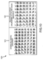
- Figure 10 provides a side-by-side comparison 1000 showing an image 1010 provided by an original combination (or dual axis) print file and an image 1020 provided by the same print file after adjustment.
- the adjustment in this example, was an enlargement of 0.7 percent via Adobe Photoshop.
- the image comparison 1000 shows how a simple pitch adjustment can ruin the pixel integrity if using a simple single axis or other traditional size adjustment technique.
- the image 1020 after adjustment is no longer pristine and the focus of the lenses of an array will likely yield a blurry image or an image that simply does not contain the targeted or desired visual effects (such as 3D in two directions or motion).
- the adjustment involving enlargement using one axis or an automatic adjustment through the rip acts to mix the images viewable by a viewer in an inconsistent way.
- ray mixing to the viewer occurs when the images of the matrices described above are reproduced or adjusted using Adobe Photoshop or other automatic processes. This is because the pixels are no longer uniform in both axes. Therefore, the lenses of a circular or square-based lens array focus on inconsistent numbers and the rays mix to the viewers. Instead of the viewer receiving all number "3's," the viewer may receive information under number "1's" and "4's” or the like at the same time. The viewing result or displayed image is of poor quality. The pixels' height and width is no longer the uniform exact height and width needed to achieve a good result as each pixel can vary in the printed image. The result is that the lenses focus on different images (rather than on the specific intended pixels), and the image is no longer pristine and, in many cases, is not even viewable.
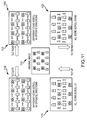
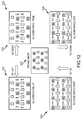
- Figures 11 and 12 illustrate two exemplary assemblies useful as anti-counterfeiting devices for currency or the like that are configured with a lens array and printed image to provide differing motion effects.
- the sets 1100 and 1200 of diagrams in Figures 11 and 12 are useful for showing how the round or square-based lens arrays when combined with a printed image with dual-axis interlacing/combination described herein can be effectively used to provide selected motion effects.
- the assemblies shown in Figures 11 and 12 are particularly useful as anti-counterfeiting devices (which may be applied to currency, product labels, and other objects/items) as they are very difficult to reproduce.
- a plan or orthogonal view 1110 of a lens/image assembly according to the present description is shown.
- the viewer is able to observe or view an original image with rows of two differing icons with the icons all being stationary or non-moving.
- the assembly is tilted or angled to the right (e.g., through or to an angle of 15 to 45 degrees or the like), and the interlacing of the matrix of frames (a set of different points of view (POVs) of the original image shown in view 1110 such as a matrix similar to that shown in Figure 7 ) is configured to cause the rows of different icons to move in opposite directions. For example, rows with padlock icons move to the right while company logos/icons move to the left.
- POVs points of view
- the assembly is tilted or angled to the left (e.g., through or to an angle of 15 to 45 degrees or the like), and the interlacing of the matrix of frames is configured to cause the rows of different icons again to move in opposite directions.
- rows of padlock icons may move to the left while the company logos/icons concurrently move to the right.
- the printed image is adapted to provide animation of the original image when the lens/printed image (or ink layer) is viewed from differing angles or points of view (e.g., the assembly or anti-counterfeiting device shown in view 1110 is pivoted about a first or vertical axis).
- the assembly of an array of lenses with an ink layer providing a dual-axis interlaced image provides animation or motion in more than one direction.
- the assembly is tilted or angled to upward (e.g., through or to an angle of 15 to 45 degrees or the like by pivoting about a second or horizontal axis of the assembly), and the interlacing of the matrix of frames (a set of different points of view (POVs) of the original image shown in view 1110 such as a matrix similar to that shown in Figure 7 ) is configured to cause the rows of different icons to move in a single direction (e.g., all move upward).
- a set of different points of view (POVs) of the original image shown in view 1110 such as a matrix similar to that shown in Figure 7
- the assembly is tilted or angled downward (e.g., through or to an angle of 15 to 45 degrees or the like about a horizontal axis of the assembly), and the interlacing of the matrix of frames is configured to cause the rows of different icons again to move in a single direction (e.g., all move downward).
- the printed image is adapted to provide animation of the original image when the lens/printed image (or ink layer) is viewed from differing angles or points of view (e.g., the assembly or anti-counterfeiting device shown in view 1110 is pivoted about a second or horizontal axis).
- a plan or orthogonal view 1210 of a lens/image assembly according to the present description is shown.
- the viewer is able to observe or view an original image with rows of two differing icons with the icons all being stationary or non-moving.
- the assembly is tilted or angled to the right (e.g., through or to an angle of 15 to 45 degrees or the like), and the interlacing of the matrix of frames (a set of different points of view (POVs) of the original image shown in view 1210 such as a matrix similar to that shown in Figure 7 ) is configured to cause the rows of different icons to move in a single direction (rather than in opposite directions as shown in 1120 of Figure 11 ).
- POVs points of view
- rows with padlock icons and company logos/icons all move to downward when the assembly (or anti-counterfeiting device) is tilted to the right.
- the assembly is tilted or angled to the left (e.g., through or to an angle of 15 to 45 degrees or the like), and the interlacing of the matrix of frames is configured to cause the rows of different icons again to move in a single direction such as upward.
- the printed image is adapted to provide animation of the original image when the lens/printed image (or ink layer) is viewed from differing angles or points of view (e.g., the assembly or anti-counterfeiting device shown in view 1210 is pivoted about a first or vertical axis).
- the animation as shown can be in a direction that is transverse relative to the pivoting directions.
- the assembly of an array of lenses with an ink layer providing a dual-axis interlaced image provides animation or motion in more than one direction.
- the assembly is tilted or angled to upward (e.g., through or to an angle of 15 to 45 degrees or the like by pivoting about a second or horizontal axis of the assembly), and the interlacing of the matrix of frames (a set of different points of view (POVs) of the original image shown in view 1210 such as a matrix similar to that shown in Figure 7 ) is configured to cause the rows of different icons to move in single direction but that one that differs from that found during left or right tilting (e.g., all move or scroll to the right).
- POVs points of view
- the assembly is tilted or angled downward (e.g., through or to an angle of 15 to 45 degrees or the like about a horizontal axis of the assembly), and the interlacing of the matrix of frames is configured to cause the rows of different icons again to move or scroll in a single direction (e.g., all move to the left).
- the printed image is adapted to provide animation of the original image when the lens/printed image (or ink layer) is viewed from differing angles or points of view (e.g., the assembly or anti-counterfeiting device shown in view 1210 is pivoted about a second or horizontal axis).
- Figure 13 illustrates a set of images or views 1300 of another lens/printed image (ink layer) assembly as may be seen by a viewer in differing positions or with the assembly tilted or moved to change the viewing angle for the viewer.
- the assembly may take the form of an array of round or square-based micro lens overlying a dual-axis interlaced image (printed onto the back, planar surface of the lens array or on a substrate (e.g., paper currency, a plastic card, a paper or plastic label, or the like) upon which the lens array is later attached).
- the interlaced image is printed using a print final that is generated as discussed above to combine a matrix of frames (e.g., sets of 2 to 4 or more frames of a single image/scene taken at differing POVs relative to the horizontal and vertical axes).
- image or view 1310 shows a straight-on or orthogonal view of the assembly or anti-counterfeiting device, and the image is a company logo in this example.
- Image or view 1320 is visible to a viewer when the assembly is tilted up as shown with arrow 1321 (the planar assembly is rotated upward about a horizontal or first axis of the assembly).
- view/image 1320 shows additional information relative to the original image seen in view 1310 such as the bottom side of the logo or object that has been the subject of the interlaced image file.
- Another image or view 1322 is visible by a viewer when the assembly is rotated or tilted to the right as shown with arrow 1323 (the planar assembly is rotated or tilted about a vertical axis (e.g., a second axis orthogonal or at least transverse to the first axis of the assembly)). More information or imagery is visible in the view 1322 such as the left side of the logo or other object that was the subject of the interlaced image file.
- FIG. 1324 Another view or image 1324 is viewed when the assembly is rotated or tilted 1325 downward (rotated about a horizontal or first axis), and, in this view 1324, information not seen in the other views is presented such as the top side of the logo or other imaged object.
- View or image 1326 provides more information or portions of the target object such as the right side of the logo/target object, and the view 1326 is visible when the assembly is rotated or tilted 1327 about a vertical or the second axis of the assembly.
- Figure 14 illustrates a set of views/images 1400 of another embodiment or implementation of a lens/printed image assembly (or anti-counterfeiting device) 1410.
- the assembly 1410 a micro lens array as described herein positioned over an dual-axis interlacing of a matrix of frames corresponding to differing images of a scene/object from differing points of view
- the front surface 1411 is provided by the outer surfaces of an array of round or square-based lenses.
- the viewer can see a background that contains a static wallpaper pattern (of icons and padlocks).
- the icons/image components may appear very deep in the plane of the film and may be visible in each viewing angle (e.g., are visible in views 1414, 1416 when the assembly 1410 is tilted right or left).
- the overlay pattern is in the plane of the film but is not visible (or only slightly visible) when viewed straight on as shown in view 1412 (but can be seen in views 1414 and 1416).
- View 1416 is useful for showing a display provided by the interlaced image of assembly 1410 when the assembly is tilted at a shallow angle (tilted or rotated slightly to the left about a vertical axis).
- a shallow angle e.g., up to about 15 degrees or the like
- the overlay pattern is only visible in black on the area of the film or front surface 1411 of the assembly 1410 that is closest to the viewer.
- the printed image may be configured such that tilting slightly (e.g., less than about 15 degrees) in any side direction (up, down, left, or right or rotating of the assembly 1410 about either the vertical or horizontal axis) cases the overlay pattern to gradually become visible (appears black in this example).
- the pattern is an "overlay" that appears to be on the top or covering over the icons or wallpaper pattern in the plane of the film (or outer surface 1411 of the assembly 1410).
- the overlay is first visible on the portion of the film or assembly 1410 closest to the viewer.
- the assembly 1410 is tilted further away from the viewer (such as to angles of about 30 to 45 degrees or more)
- more and more of the overlay pattern gradually becomes visible until the entire overlay pattern is visible when the assembly 1410 is viewed via surface 1411 at a predefined more extreme angle (e.g., an angle of 45 to 60 degrees or more relative to the normal view 1412).
- This can be seen in extreme angle view 1414 of Figure 14 where the assembly 1410 is rotated about a vertical axis (e.g., to the right) more than about 60 degrees.
- the overlay pattern is fully visible over the wallpaper pattern with the icons (logos and padlocks in this example) over the entire surface 1411 of the assembly/film 1410.
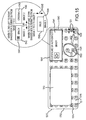
- Figure 15 illustrates an assembly 1510 of another embodiment of the present description.
- the assembly 1510 may be configured for use as an anti-counterfeiting device or label with a body/substrate, an ink layer providing a printed image with dual-axis interlacing of a matrix of differing POV frames as discussed herein, and an array of round or square-based lenses for viewing the printed image.
- the assembly 1510 may be a label (e.g., a 2-inch by 1 inch or other sized label) that may be printed down a web on 1.125-inch centers or the like during its manufacture.
- the assembly 1510 includes a front or upper surface 1512 (e.g., a thin lens array formed of transparent or at least translucent plastic or similar material) through which an interlace image may be viewed as shown.
- the printed image may include a void or blank space as shown with white (or other-colored) box 1513, which may be used for printing (e.g., flexo) barcodes and/or human-readable text, which may be added offline or in later processing (e.g., via thermal transfer printing).
- the assembly/label 1510 has a printed image has been specifically designed to provide a number of images and effects to make it more difficult to reproduce and to allow a viewer to readily verify its authenticity.
- the printed image presents a gray background 1516 (e.g., that may be subsurface printed (e.g., flexo)) upon which icons or symbols 1514, 1516 (colored and/or black) may be printed or layered.
- the symbol 1516 may take the form of a boundary (e.g. a circle) in which a second symbol or text 1517 is provided such as text (e.g., "OK") that should be completely inside the boundary to show the label 1510 is not a counterfeit or is authentic.
- the printed interlaced image may also include devices/components for further allowing a viewer to check the authenticity of the label 1510.
- a magnifying glass image 1520 may be incorporated into printing plates used to fabricate the assembly/label 1510 and appear on the plane of the film or surface 1512.
- One or more of the icons/symbols 1523, 1525 may be provided within the image 1520 such under the glass of the magnifying glass of image 1520.
- the printed image may be configured such that, when a viewer looks through the glass area of image 1520, the icons 1523 appear black and the icons 1525 appear blue, which may be a different color than these icons 1514, 1516 in the rest of the label 1510 (e.g., reverse the coloring of these icons when viewed under the glass image 1520). Further the icons 1523 and 1525 under the magnifying glass image 1520 may appear to be somewhat larger in size than the corresponding wallpaper/background versions of these icons 1514, 1516.
- the wallpaper icons 1530 may be designed to move in opposite (or the same) directions when the assembly 1510 is tilted about a first axis (e.g., the assembly/label is rotated/tilted to the left or right) while moving in the same (or opposite) directions when the assembly 1510 is tilted about a second axis (e.g., the assembly/label is rotated/tilted upward or downward).
- the corresponding icons/symbols 1523, 1525 under the magnifying glass image 1520 may be designed to move differently than those 1530 that are not under the glass.
- the icons 1523, 1525 may move together in a single direction under the glass image 1520 while the icons 1530 move in opposite directions when the assembly 1510 is rotated/tilted about a particular axis.
- the printed image under the lens array of assembly 1510 may further include a further element (e.g., a boxed/bordered display) 1540 to enhance security (or limit counterfeiting efforts further).
- the element 1540 may include a border 1541, which may be formed of a pattern that is difficult to reproduce such as a 0.15-mm (or other size) microtext border containing one or more intentional misspellings (e.g., the border appears solid to the naked eye of a viewer but misspelled words are evident under a microscope).
- a first image is displayed but, as shown in the exploded view, a second image 1542 is displayed in the element 1540 when the assembly 1510 is rotated 1543 about a first axis (e.g., rotated right or left about a vertical axis of assembly 1510).
- a third image 1544 may be displayed in the element 1540 when the assembly 1510 is rotated 1545 in another direction (e.g., rotated up or down about a horizontal axis of assembly 1510).
- Figure 16 illustrates a system 1600 adapted for use in fabricating of an assembly such as an anti-counterfeiting device as described herein.
- the system 1600 includes an imaging workstation 1610 with a processor 1612 for executing code or software programs to perform particular functions.
- the workstation 1610 may take the form of nearly any computer device with the processor 1612 acting to manage operation of input and output devices 1614 such as devices for allowing an operator of the station 1610 to view and input data useful by the mapping and imaging module 1620 to create a print file 1648 communicated as shown at 1675 to a print controller 1680.
- the CPU 1612 also manages memory 1630 accessible by the mapping and imaging module 1620.
- the mapping and imaging module 1620 performs the functions useful in performing the functions and processes described herein such as for generating frame sets 1640 from an original image 1632, creating a frame matrix 1646 from these image sets 1640, and producing a bidirectional bit map or print file 1648 from the frame matrix 1646.
- the memory 1630 may be used to store an original image 1632 that may include a background 1634 as well as one or more icons/symbols 1636 that may be provided as wallpaper (e.g., these elements may be layered over the background 1634).
- the module 1620 may act to generate a number of sets of frames 1640 from the original image 1632, and each of the sets 1640 may include 2 to 10 or more frames from differing points of view of the original image (e.g., see the sets of frames shown in Figure 7 that provide differing POV frames along two axes (X and Y axis frames/images of a base or original image 1632)).
- the module 1646 may generate a frame matrix 1646 as discussed above to properly map the pixels to provide proper X and Y axis interlacing with or without a motion effect.
- a bidirectional pixel map or print file 1648 is generated by combining the rows and columns of the matrix 1646 with proper sequencing (with all 3D and/or motion information in both directions such as with squares with the data from the matrix 1646 rather than stripes).
- the mapping and imaging module 1620 may generate the print file 1648 based on a variety of imaging/mapping parameters 1650.
- the lens array design information 1652 including whether the lenses are round or square, the optical pitch 1654, and the LPI 1656 values may be taken as input by the module 1620 to create the print file 1648.
- the device output resolution 1670 may be used by the module 1620 to create the print file 1648 such as to set the number of frames in the sets 1640 or the like.
- the parameters 1650 may also include motion parameters 1660 to define how to animate the original image with tilting/rotating of an assembly such as by setting the direction of movement of the icons/symbols and how fast movement occurs (how much rotation needed to achieve a particular motion effect and so on).
- the parameters 1650 may also include color parameters 1666 such as whether or not icons/symbols change colors with rotation of an assembly with an image printed from file 1648 and what such colors should be in the displayed image.
- the imaging workstation 1610 may communicate (in a wired or wireless manner such as over a digital communication network) this file 1648 to a print controller 1680 (e.g., another computer or computing device).
- the print controller 1682 may use this print file 1648 to fabricate a printing or embossing plate 1682, which can then be used to emboss a surface such as the planar/back side of a lens array with fabrication device 1684.
- This embossed surface can then be filled with one or more coatings/layers of ink to form a printed image in a lens array/printed image assembly (e.g., an anti-counterfeiting device).
- the controller 1680 may also use the print file 1648 to provide a digital file 1670 to a color, digital printer 1674 for printing of the dual-axis interlaced image on a surface such as the planar back side of a lens array or on a side of a piece of paper currency or a product label over which a lens array is later applied to provide an anti-counterfeiting device on the currency/label.
- FIG. 17 illustrates with a flow diagram a pixel adjustment method 1700 according to the present description.
- the method 1700 includes at 1710 performing a print test (e.g., with components 1680 to 1684 of Figure 16 ) to determine the optical pitch, in the X axis and also in the Y axis, of a lens array, which as discussed above, may vary from design.
- a target visual pitch is selected for a desired or input viewing distance (again, in the X and Y axes).
- the method 1700 may involve setting the target pitch at 416.88 for the X axis and 384.47 for the Y axis.
- the method 1700 continues at 1740 with interlacing the X and Y axes in the pixel map. This typically involves mapping at the nearest device output for the desired target pitch (e.g., 400 output is near to the pitches set at step 1730).
- the method 1700 includes calculating the different between the device output and the target optical pitch.
- the difference in the X axis is +4.22 percent (i.e., Target Pitch of 416.88 divided by the device output of 400) and the difference in the Y axis is -3.9 percent (e.g., Target Pitch of 384.47 divided by the device output of 400).
- the mapping and imaging module/software program acts to remove pixels based on the differences determined in step 1750.
- the module may remove 4.22 percent of the pixels by specifically targeting low information areas in the X axis.
- the module may also act to add 3.9 percent pixels in the Y axis.
- Step 1770 of method 1700 further explains this process with the module acting to identify pixels with less information for removal (e.g., evenly in the X axis in this example) while the adding of pixels may be performed by blending pixels (e.g., nearby pixels) (e.g., blending pixels are added in the Y axis).
- plates are output based on the print file modified to provide pixel adjustment.
- the plates for printing may be output at 4800 pixels in the X axis and 4800 pixels in the Y axis.
- the process 1700 retains integrity of the displayed image without blur, e.g., due to re-resolution pristine pixels.
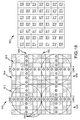
- FIG. 18 is useful for further explaining the process of providing dual-axis interlacing for a lens array of the present description.
- a small lens array or lenslet 1810 is shown in a plan or top view that includes four lenses 1812, 1814, 1816, and 1818 (with a more typical array having many more lenses).
- the lenses 1812, 1814, 1816, and 1818 are round-based lenses in this non-limiting example.
- a dual-axis printed image (or ink layer with a printed image) can be provided with each of the boxes 1813 in the figure being used to represent a pixel. Further, each of these "pixels" 1813 can be considered to be a lens focus point.
- the printed image provided in pixels 1813 when combined with lens array 1810 provides a display device that can be used to provide full 3D imagery as well as multi-directional motion.
- each lens 1812, 1814, 1816, 1818 may be used to display a looping image.
- the diagonal sets of pixels 1830 shown with shading may be used to provide a 45 degree tilt loop sweep while the horizontal and vertical sets of pixels 1820 shown with "stars" may be used to provide a side-to-side and up-and-down image loop.
- graph 1850 is useful for illustrating how an arrangement of 7 pixels by 7 pixels provided under each lens 1812, 1814, 1816, and 1818 may be printed with dual-axis combined/interlaced images to provide these effects.
- a mapping and imaging module (such as module 1620) may be used to select the proper frames to generate such a matrix and/or print map, and a print file can be generated from this mapping for use in printing the dual-axis interlaced images in each pixel as shown in graph 1850 so as to provide the visual effects described with pixels 1820, 1830.
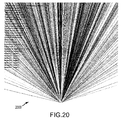
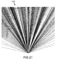
- Figures 19-21 are plots 1900, 2000, and 2100 showing ray tracing for assemblies of the present description, e.g., for a lens array combined with a dual-axis interlaced image.
- Figure 19 illustrates a plot 1900 of a tracing of rays 1920 using an assembly 1910 (e.g., an anti-counterfeiting device) configured as described herein.
- the assembly 1910 includes a lens array 1912 of round-based lenses 1914 overlying an ink layer/printed image 1916 including a number of interlaces 1918 (7 images are interlaced using dual-axis interlacing).
- the plot 1900 shows rays 1920 traced from idealized lenticular interlaced stripes 1918 in printed image/ink layer 1916.
- the order of the interlaces was modified so that to the viewer the image is properly interlaced.
- the radius of each lens 1914 was 1.23 mils
- the lenses 1914 were provided at 408 LPI
- the lenses 1914 were 3 mils thick
- the index of refraction was assumed to be 1.49.
- only zero width interlaces were represented with 7 interlaces 1918 per sets of two lenses 1914. Tracings were made over a range of +30 degrees to -30 degrees with 5 degree steps showing the near lenticule region.
- the plot 2000 is a filled-in ray trace showing a larger overall of view of the plot 1900 of Figure 19 .
- the interlaces for plot 2000 were taken to be 2 mils wide with 7 interlaces provided per set of two lenses. Five steps per interlace were traced, the range was +30 degrees to -30 degrees using 1 degree steps.
- the sequence of the interlaces was 6, 4, 2, 3, 7, 5, and 1.
- the plot 2100 is a trace done with a normal sequence of the interlaces (e.g., 1, 2, 3, 4, 5, 6, and 7) for a lens of radius 1.23 mils, lenses provided at 408 LPI, a lens thickness of 3 mils, and an index of refraction of 1.49.
- the lens width was taken at 2 mils, and there were 7 interlaces provided for each set of two lenses. Five steps were traced across each lens again with a range of +30 degrees to -30 degrees with 1 degree steps.
- the plots 1900, 2000, and 2100 show coding that is done by having multiple interlaces per multiple lenticules and the change in distribution to the viewer by changing the interlace sequence.
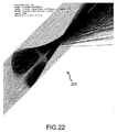
- Figure 22 is a plot 2200 of an off-axis ray tracing while Figure 23 is a corresponding spot diagram 2300 that may be generated to analyze a planned array/image design.
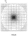
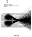
- Figures 24 and 25 are two additional spot plots or diagrams 2400 and 2500 for a round-based lens (or spherical lens), while Figure 26 is a plot 2600 of a ray tracing for the lens associated with the plots of Figures 24 and 25 .
- the radius of the lens for these latter three figures was 5 units and the focal plane was about 10 units (e.g., the units may be any unit such as mils).
- the description teaches a display assembly (e.g., an anti-counterfeiting device) that includes an array of round or square lenses combined with an ink layer with a printed image/pattern.
- the lens arrays are made up nested round or square lenses arranged as shown in Figures 3A-4B .
- the printed image/pattern provided in the ink layer (or layers) are aligned with the lens arrays (e.g., with the X and Y axes of the printed image), and the printed image/pattern is made up of vertically and horizontally mapped pixels (e.g., printed using a print file defining dual-axis interlacing (or interlacing in two axis) of frames of a matrix as discussed herein).
- the pixels may be of any type and often are adapted to match the output device with the viewer's optical pitch in two axes.
- the lens arrays may be provided at 200 or more LPI in both directions so as to provide 4000 lenses or more per square inch.
- the focal lengths of the lenses may vary, but some arrays have been implemented that have focal lengths of less than about 10/1000 inches for round and for square-based lenses.
- the printing of the dual-axis interlaced image for use with a lens array may be performed using one or more colors using the pixel mapping provided in a generated print file.
- diffractive techniques are used to create color with the separation of wave lengths, purposefully or accidentally, within the interlaced image in a round-based lens array.
- the printing step involves printing of an X and Y pixel-imaged file or pixel map so as to produce a printing plate or a digital image, either of which may be used to provide an ink layer with a printed image/pattern that is useful in combination with the round and square-based lenses as nested in an array as described herein (e.g., printing on the back or planar surface of the lens material to provide the X and Y axis pixel mapped images).
- an embossing plate is produced for use to emboss the back of the lens material (lens array). Then, the embossed back surface is filled with ink or metalized for use in holography in combination with a round or square-based lens array.
- printing may also occur on the front or contoured surface of the lens array.
- the printing may involve printing features, colors, or images directly on top of the lenses (i.e., the non-planar side of the lens array) in combination within printing on the back or planar side of the lenses using interlaced images.
- a number of unique visual or display effects can be achieved with the printed image viewed through one of the lens arrays of the present description.
- image mapping of the X and Y axes may be performed so that a wallpapered array of repeating icons (e.g., the company logos and padlocks of the exemplary figures) scroll or move across the substrate in opposite directions to each other when the substrate (or assembly or anti-counterfeiting device) is tilted left and right (rotated about a vertical or first axis) and in the same direction when the substrate is tilted up and down (rotated about a horizontal or second axis transverse to the first axis).
- This effect may be called "Continuum Movement in Opposite Directions."
- the image mapping is performed so that a wallpapered array of repeating icons moves or scrolls up and down across the surface of the assembly/anti-counterfeiting device when the assembly/device is tilted left and right (icons all move in the same direction) and left and right when the assembly/device is tilted up and down (again, all icons move in the same direction) (e.g., tilt left causes all icons to scroll or move upward, tilt right causes all icons to scroll move down, tilt up causes all icons to scroll right, and tilt down causes all icons to scroll left).
- This effect may be labeled "Continuum Movement in Orthogonal Directions.”
- Image mapping of the X axis and Y axis pixels may be performed such that when a volumetric icon or image like a company logo or a symbol has five viewable sides (e.g., a top side, a bottom side, a left side, a right side, and a face or front side). These five sides are viewable in three dimensions, with apparent depth and in full parallax, when the assembly/device is tilted or rotated in differing directs (orthogonal/normal view, tilt left, tilt right, tilt upward, and tilt downward or a positioning therebetween).
- the face of the 3D logo/symbol/icon may be a different color than the sides to create a more noticeable 3D effect, and this effect may be called "full volume 3D.”
- Another effect that can be achieved via the image mapping of the X axis and the Y axis described herein is to provide wallpaper with icons with another overlay pattern.
- the overlay pattern may be provided in the print file and resulting printed image so that it is hidden from view when the assembly is viewed from certain POVs (such as a normal POV) but gradually becomes more and more visible (in the plane of the film and wallpaper pattern) on top of the icons/symbols/logos of the wallpaper (such as when moved to angles of 30 to 60 degrees or the like from normal).
- POVs such as a normal POV
- processors include, but are not limited to, digital computer systems, microprocessors, application-specific integrated circuits (ASIC), general purpose computers, programmable controllers and field programmable gate arrays (FPGAs), all of which may be generically referred to herein as "processors.”
- ASIC application-specific integrated circuits
- FPGA field programmable gate arrays
- signal processing may be incorporated by an FPGA or an ASIC, or alternatively by an embedded or discrete processor. Therefore, other embodiments include program instructions resident on computer readable media which when implemented by such means enable them to implement various embodiments.
- Computer readable media include any form of a non-transient physical computer memory device.
- Examples of such a physical computer memory device include, but are not limited to, punch cards, magnetic disks or tapes, optical data storage systems, flash read only memory (ROM), non-volatile ROM, programmable ROM (PROM), erasable-programmable ROM (E-PROM), random access memory (RAM), or any other form of permanent, semi-permanent, or temporary memory storage system or device.
- Program instructions include, but are not limited to, computer-executable instructions executed by computer system processors and hardware description languages such as Very High Speed Integrated Circuit (VHSIC) Hardware Description Language (VHDL).
- VHSIC Very High Speed Integrated Circuit
- VHDL Hardware Description Language
Description
- The present invention relates, in general, to combining printed images with lens arrays to display three dimensional (3D) images with or without motion, and, more particularly, to a method of pixel mapping, providing arrangements of pixels, and imaging that is adapted for use with arrays of square or round-based micro lenses to provide enhanced 3D imagery with fuller volume and/or with multi-directional motion.
- There are presently many applications where it is desirable to view a printed image via an array of lenses. For example, anti-counterfeiting efforts often involve use of an anti-counterfeiting device or element that is made up of an array of lenses and an image printed onto the back of the lens array or onto an underlying substrate or surface (e.g., a sheet of paper or plastic). The anti-counterfeiting element may be used to display an image that is chosen to be unique and be an indicator that the item carrying the anti-counterfeiting element is not a counterfeit. The anti-counterfeiting market is rapidly growing worldwide with anti-counterfeiting elements placed on a wide range of items such as upon currency (e.g., on a surface of a paper bill to help prevent copying) and on labels for retail products (e.g., labels on clothing showing authenticity).
- In this regard, moire patterns have been used for years in anti-counterfeiting elements with arrays of round lenses and with arrays of hexagonal arrays (or round and hexagonal lens arrays). Typically, the printed images provided in an ink layer under these lens arrays are small, fine images relative to the size of the lenses. A moire pattern is provided in the printed images in the form of a secondary and visually evident superimposed pattern that is created when two identical patterns on a surface are overlaid while being displaced or rotated a small amount from each other.
- In such moire pattern-based anti-counterfeiting elements, some of the images may be printed in a frequency slightly more or less frequent than the one-to-one dimension of the lenses in two axes, and some of the images may be printed slightly differently relative to each other.
Figure 1 illustrates anexemplary assembly 100 that may be used as an anti-counterfeiting element. Theassembly 100 includes alens array 110 made up of side-by-side, parallel columns (or rows) 112 ofround lenses 114, and it can be seen that thecolumns 112 are offset from each other (by about 50 percent) such that pairs ofadjacent lenses 114 in the columns are not aligned (e.g., a lens in a next column is positioned in the space between two lenses in the previous column). - A printed image 120 is provided in a layer of ink underneath the lens array 110 (on a back, planar surface of the lens array 110). The result, which is difficult to see in
Figure 1 , is a moire pattern that provides the illusion of depth of field to a viewer via thelenses 112 of thearray 110 or, in some cases, the sense that the images are moving (motion or animation of the displayed items). Typically, the thickness of each of thelenses 112 is in the range of 0.5/1000 to 5/1000 inches (or 12 to about 125 microns), and the frequency of theselenses 112 in anarray 110 is about 400X 400 to over 1000X 1000 per inch. - While helpful to reduce counterfeiting, use of moire patterns with round lens arrays has not been wholly satisfactory for the anti-counterfeiting market. One reason is that the effects that can be achieved with moire patterns are limited. For example, one cannot take a photograph and display 3D with a moire pattern. Generally, the moire patterns are used in the security and/or anti-counterfeiting industry in very fine lenses with focal lengths of about 20 to 75 microns and frequencies of over 500 lenses per inch in one axis or more than 250,000 lenses per square inch. As a result, the images underlying the lenses in the lens array are typically printed at least at 12,000 DPI (dots per inch) and may even be provided at over 25,000 DPI. These micro-lens arrays are generally closely nested as shown in
element 200 with itsarray 210 inFigure 2 . Thearray 210 uses hexagonal lenses that are provided in offset and overlapping columns 212 (e.g., side-by-side lenses 214 are not aligned in a row and are positioned to fill or be nested into space between two lenses of adjacent columns 212) to focus on an image ormoire pattern 220 in an underlying ink layer. - One problem or issue with the use of such an
array 210 andimages 220 is that theelement 200 is relatively easy to reverse engineer, which limits its usefulness as an anti-counterfeiting element. Particularly, thepatterns 220 underlying thelenses 214 can be seen with an inexpensive and readily available microscope, which allows one to determine the frequency of the images and patterns. In addition, thelenses 214 can be cast and re-molded, which leaves printing the identified images as the only hurdle for successfully copying the element 200 (and then counterfeiting a piece of currency or a label for a product). Unfortunately, printing theimage 220 is becoming easier to accomplish due to high resolution lasers and setters and other printing advances. Typically, for anelement 200, the micro-lenses are printed using an emboss and fill technology, which limits the printing to one color due to the fact that the process tends to be self-contaminating after one color and also due to the fact that the process is difficult to control from a relative color-to-color pitch in the emboss-and-fill printing process. - Hence, there remains a need for advancements in the design and fabrication of assemblies or elements that combine a lens array with a printed image (layer of ink containing images/patterns) to display imagery. Such improvements may allow new anti-counterfeiting devices or elements to be produced for use with currency, labels, credit/debit cards, and other items, and these anti-counterfeiting devices preferably would be much more difficult if not nearly impossible to duplicate or copy. Further, there is a growing demand for such anti-counterfeiting devices to provide a surprising or "wow factor" with their displayed imagery such as images that float above and/or below a focal plane (e.g., more true 3D displays).
- Document
US 2006/0017979 A1 discloses an assembly according to the preamble ofclaim 1. - The invention provides for an assembly according to
claim 1 ans a method according to claim 10. - Briefly, the inventors recognized that it may be beneficial to provide a different nesting of lenses in an array that can then be combined with an image having dual-axis interlacing. For example, the lenses may be circular or square-based lenses that have their centers aligned such that the array is made up of parallel rows and columns of lenses (e.g., without having adjacent lenses being offset from each other as seen in the arrays of
Figures 1 and2 ). The image is printed from a print file generated from a matrix of frames of images taken from a plurality of points of view (POVs) along both a first axis (X axis) and also along a second axis (Y axis). The frames are interlaced in both directions to provide a pixel mapping to the lenses of the array. - More particularly, a visual display assembly is provided that is useful as an anti-counterfeiting device on paper currency, product labels, and other objects. The assembly includes a film of transparent material including a first surface including an array of lenses and a second surface opposite the first surface. The assembly also includes a printed image proximate to the second surface. The printed image includes pixels of frames of one or more images interlaced relative to two orthogonal axes (printed from a file generated using dual-axis interlacing rather than single axis interlacing as in conventional lenticular printing). The lenses of the array are nested in a plurality of parallel rows, and adjacent ones of the lenses in columns of the array are aligned to be in a single one of the rows (e.g., no offsetting of adjacent lenses).
- To provide the lens array, the lenses may be round-based lenses or are square-based lenses. The lenses of the array are provided at 200 LPI (or a higher LPI) as measured along both of the two orthogonal axes. The lenses may each have a focal length of less than 10/1000 inches. In some embodiments, the frames each include a different point of view (POV) of the one or more images. In such cases, the frames include images from at least three POVs along a first of the two orthogonal axes, and the frames further include images from at least two additional POVs corresponding to each of the three POVs along the second of the two orthogonal axes.
- In the assembly, the printed image may be adapted such that an image displayed from a normal POV includes a first set of symbols and a second set of symbols, and, in an image displayed when the assembly is rotated from the normal POV about a first axis, the first and second sets of symbols move in opposite directions. Further, the printed image may be adapted such that in an image displayed, when the assembly is rotated from the normal POV about a second axis orthogonal to the first axis, the first and second symbols move in a single direction that is orthogonal to the second axis.
- In other assemblies, the printed image can be adapted such that an image displayed from a normal POV includes a first set of symbols and a second set of symbols, and, in an image displayed when the assembly is rotated from the normal POV about a first axis, the first and second sets of symbols can move in a single direction that is parallel to the first axis of the assembly. In such embodiments of the assembly, the printed image is adapted such that in an image displayed when the assembly is rotated from the normal POV about a second axis orthogonal to the first axis, the first and second symbols move in a single direction that is parallel to the second axis.
- Another visual effect is achieved in other embodiments of the assembly. Particularly, the printed image may include a wallpaper pattern (e.g., with icons, logos, and other symbols) and an overlay pattern. Then, the printed image may include mapped pixels such that the wallpaper pattern is visible from a plurality of POVs (when the assembly is rotated/tilted to differing angles relative to a viewer's line of sight), and the overlay pattern has a range of differing visibilities over the plurality of POVs. For example, the differing visibilities may include the overlay being invisible (or only faintly visible) to a viewer along a normal POV of the assembly while rotating or tilting the assembly away further and further from normal (in any direction in some cases) causes the darkness or brightness of the overlay pattern to increase until it is fully visible (or as dark or bright in color as it can be such as at some more extreme angle relative to normal such as an angle in the range of 45 to 60 degrees or the like).
-
-
Fig. 1 is a top view of an assembly used as an anti-counterfeiting element or device with a lens array made up of side-by-side and vertically offset columns of round lenses (e.g., lenses are not arranged in linear rows in the array) overlying a printed moire pattern; -
Fig. 2 is a top view, similar to that ofFig. 1 , showing an assembly used as an anti-counterfeiting element or device with a lens array made up of side-by-side and vertically offset columns of hexagonal lenses (e.g., lenses not arranged in linear rows and tightly nested in abutting contact) overlying a printed moire pattern; -
Figs. 3A and 3B illustrate a top and sectional view taken atline 3B-3B, respectively, of an item such a piece of paper currency or a product label with an anti-counterfeiting device based on a round lens array; -
Figs. 4A and 4B illustrate a top and sectional view taken atline 4B-4B, respectively, of an item such as a paper currency or label with an anti-counterfeiting device or element provided on a surface that is based on a square lens array; -
Fig. 5 shows a process of obtaining frames or images associated with differing points of view taken of a scene along the horizontal or X-axis; -
Fig. 6 shows a process of obtaining frames or images associated with differing points of view taken of the scene ofFig. 5 along the vertical or Y-axis; -
Fig. 7 illustrates a larger set of frames or images obtained by taking differing viewpoints of a scene at each point along the X-axis (or Y-axis), e.g., multiple sets of frames to provide height; -
Fig. 8 illustrates an image provided by an exemplary interlaced file for one row of a matrix of frame files associated with multiple points of view (e.g., a vertically combined file); -
Fig. 9 illustrates an image provided by a combination print file (or two-way interlacing file or X and Y axis combination file) for use with a lens array of the present description; -
Fig. 10 illustrates a side-by-side comparison of an image of an original combination print file and an image of a combination print file adjusted (enlarged) as discussed in the description; -
Figs. 11 and12 illustrate views of two exemplary assemblies viewed from differing POVs, with the assembly being useful as anti-counterfeiting devices for currency or the like that are configured with a lens array and printed image to provide differing motion effects; -
Fig. 13 illustrates a number of views of another exemplary lens/printed image (ink layer) assembly (or anti-counterfeiting device) from a number of differing POVs; -
Fig. 14 illustrates a normal (or orthogonal/plan) view and tilted left and right views of another lens/printed image assembly (anti-counterfeiting device); -
Fig. 15 illustrates an assembly (e.g., an anti-counterfeiting device in the form of a label) incorporating a micro lens array provided over an ink layer containing a dual-axis interlaced set of images as described herein; -
Fig. 16 is a functional block diagram or schematic of a system for use in manufacturing anti-counterfeiting devices or lens/printed image assemblies of the present description; -
Fig. 17 illustrates a flow diagram of 0a pixel adjustment method according to the present description and as may be implemented with the system ofFig. 16 ; -
Fig. 18 provides a schematic and a print file (pixel mapping) showing a process of providing dual-axis interlacing of image frames to achieve visual effects described herein; -
Figs. 19-21 are plots showing ray tracing for assemblies of the present description, e.g., for a lens array combined with a dual-axis interlaced image; -
Fig. 22 is plot of an off-axis ray tracing; -
Fig. 23 is a spot diagram corresponding to an off-axis analysis ofFig. 22 ; -
Figs. 24 and25 are two additional spot plots or diagrams for a round-based lens (or spherical lens); and -
Fig. 26 is a plot of a ray tracing for the lens associated with the plots ofFigures 24 and25 . - Briefly, the present description is directed toward designs for assemblies of lens arrays combined with printed images provided in an ink layer. The assemblies can be used, for example but not as a limitation, as anti-counterfeiting elements or devices. The lens arrays differ from those shown in
Figures 1 and2 , in part, because the lenses are arranged in columns that are not vertically offset such that the lenses are provided in parallel columns and also in parallel rows (e.g., pairs of adjacent lenses in side-by-side columns are aligned with their center axes being collinear). The lenses may be round or square-based, and the underlying image has its pixels mapped and arranged such that the micro lens arrays produce a 3D displayed image with full volume and, in some cases, with multi-directional motion or animation. - In an embodiment shown in
Figures 3A and 3B , an item 300 (such as a piece of paper currency, a label for a product, or the like) is provided with an anti-counterfeiting element or device in the form of a lens array (round lens array) 310 covering or provided on top of a layer ofink 320 providing a printed image. As shown, theitem 300 includes a substrate orbody 305 such as a sheet of paper or plastic (e.g., paper to be used as currency or paper/plastic to be used for a product label). On asurface 307 of the substrate/body 305, an image is printed via a layer ofink 320, and alens array 310 is provided on an exposed surface of the ink layer 320 (e.g., theink layer 317 and its pattern/image may be printed onto thesubstrate surface 307 or onto the back surface of the lens array 310). - As shown, the
lens array 310 is made up of a plurality oflenses 314 that each have around base 317 abutting thesurface 321 of theink layer 320 and have a dome-shaped cross section as seen inFigure 3B . The round-based lenses orround lenses 314 are arranged in a number ofcolumns 312 that are parallel as shown by parallel vertical or Y-axes 313 (axes passing through the center of thelenses 314 in columns 312) inFigure 3A . Further, thelenses 314 are arranged such that pairs oflenses 314 in adjacent ones of thecolumns 312 are in contact or proximate at least at the bases 317 (as seen inFigures 3A and 3B ). Still further, thecolumns 312 are not vertically offset as seen inarrays Figures 1 and2 such that pairs ofadjacent lenses 314 are aligned in rows as can be seen by parallel horizontal orX-axes 315 passing through centers oflenses 314 in the array 310 (e.g., thelenses 314 of thearray 310 are both vertically and horizontally aligned due to the specific nesting shown inFigure 3A ). - In an embodiment shown in
Figures 4A and 4B , an item 400 (such as a piece of paper currency, a label for a product, or the like) is provided with an anti-counterfeiting element or device in the form of a lens array (round lens array) 410 covering or provided on top of a layer ofink 420 providing a printed image. As shown, theitem 400 includes a substrate orbody 405 such as a sheet of paper or plastic (e.g., paper to be used as currency or paper/plastic to be used for a product label). On asurface 407 of the substrate/body 405, an image is printed via a layer ofink 420, and alens array 410 is provided on an exposed surface of the ink layer 420 (e.g., theink layer 417 and its pattern/image may be printed onto thesubstrate surface 407 or onto the back surface of the lens array 410). - As shown, the
lens array 410 is made up of a plurality oflenses 414 that each have asquare base 417 abutting thesurface 421 of theink layer 420 and may have a dome-shaped cross section as seen inFigure 4B . The square-based lenses orsquare lenses 414 are arranged in a number ofcolumns 412 that are parallel as shown by parallel vertical or Y-axes 413 (axes passing through the center of thelenses 414 in columns 412) inFigure 4A . Further, thelenses 414 are arranged such that pairs oflenses 414 in adjacent ones of thecolumns 412 are in contact or proximate at least at the bases 417 (as seen inFigures 4A and 4B ). Still further, thecolumns 412 are not vertically offset as seen inarrays Figures 1 and2 such that pairs ofadjacent lenses 414 are aligned in rows as can be seen by parallel horizontal orX-axes 415 passing through centers oflenses 414 in the array 410 (e.g., thelenses 414 of thearray 410 are both vertically and horizontally aligned due to the illustrated nesting of the lenses 414). - In the
lens arrays Figures 3A and4A so that there is little or no interference from the adjoining or adjacent lenses when an image in ink layers 320, 420 are viewed by a viewer of theitems lenses ink layer lenses 314 may be preferred as these produce a fuller or full-filled image. - The ink layers 320, 420 are adapted or designed for use with the
lens arrays lenses lens arrays 310, 410) to the viewer is a 3D image in all directions, regardless of the viewpoint. - At this point, it may be useful to compare and contrast the effects that can be produced with a pixel mapping arrangement in ink layers 320, 420 combined with the lens arrays 310, 410 versus a conventional moire pattern-based assembly (see those shown in
Figures 1 and2 ) with the following effect listing: (1) float is provided by both moire and pixel mapping according to the present description; (2) float height is limited to 100 percent with moire patterns while 150 percent float can be achieved with pixel mapping-based embodiments; (3) 1-directional motion is provided by both techniques; (4) on-off is available/achievable only with pixel mapping techniques; (5) animation is also only available with the pixel mapping-based embodiments; (6) zoom cannot be provided using moire patterns but can be provided with pixel mapping; (7) true 3D is provided only with the pixel mapping-based embodiments described herein; (8) movement in opposite direction is also achievable only with the pixel mapping-based embodiments of the present description; (9) one image up/one side is another effect available only with the use of the pixel mapping-based embodiments; and (10) full volume 3D is only available via the use of the lens arrays and pixel mapping taught herein. As a result of some or all of these effects or aspects of the two techniques, the moire pattern-based anti-counterfeiting devices are easily reverse engineered while the pixel mapping-based anti-counterfeiting devices are impossible or nearly impossible to reversed engineer. - With a general understanding of the lens arrays and their configurations understood, it may be useful to discuss pixel arrangement, imaging, and mapping for circular-based and square-based lenses (e.g., design of the ink layers of the assemblies shown in
Figures 3A-4B ). Traditional lenticular printing (interlaced printing of images for use with lenticular lens arrays) uses a certain number of files that are created from different points of view (or viewpoints) in order to get a 3D effect. For example, a point of view in a single plane is moved to the left or to the right to create a next point of view. Traditional lenticular printing also uses different frames from a sequence of images to create some motion or animation or other visual effects. Once generated, the set of frames or files are combined in an interlaced file that is then printed onto the back of a lenticular lens array or onto a substrate upon which the lenticular lens array can be applied. The process to create the final file from the original frames is called "interlacing" (e.g., the process of striping and arranging printed information to a given pitch to match a particular lenticular lens array). - The interlacing on traditional lenticular material has just one direction, and the interlacing depends on the lens direction so that the striping is either horizontal or vertical). This process combines the frames so that the observer can see the effect working either in horizontally or vertically (but not both) according the lens direction.
Figure 5 illustrates aprocess 500 in which a set of files of a single image orscene 540 viewed from threedifferent viewpoints 510, 520, and 530 (such as -45 degrees, orthogonal, and +45 degrees or the like) are obtained for use in printing. Theviewpoints viewpoints - As shown in
Figures 3A-4D , circular and square-based lenses may be used in a lens array with a printed image, and these lenses allow the effects to work in two directions concurrently, e.g., in the horizontal and vertical directions at the same time. The fact that the visual effects are created in all directions also demands that a more complete set of frames or views from the same scene be provided in the printed image (or ink layer) used with round or square lens arrays. With this recognition by the inventors, the inventors developed a new process (described below) for interlacing (or, more accurately, mapping, arranging, and imaging pixels) these sets of frames from a single scene. - For example, circular or round-based lenses allow one to have not only one set of points of view as shown in
Figure 5 that may be useful with traditional lenticular lenses but to also have different sets of points of views from differing heights (or along the vertical or Y-axis).Figure 6 shows aprocess 600 for obtaining additional frames or views from the scene 640 (which may be the same as scene/image 540). As shown, frames 610, 620, 630 from three different viewpoints (e.g., +45 degrees relative to orthogonal to the Y-axis, orthogonal to the Y-axis, and -45 degrees relative to the Y-axis or the like) are obtained from animage 640 of a single scene. - One of the main differences between the presently described process and traditional lenticular printing, though, is the fact that now two or more sets of points of views or frames corresponding to such viewpoints is combined in an image file for printing. In other words, the interlacing is performed for view points along the vertical and along the horizontal axis. This means that instead of interlacing one sequence of frames the new interlacing process (or print file generation process) involves intelligently mapping a matrix of frame corresponding to differing viewpoints taken along both the X and Y-axes. In the present example, as shown in diagram 700 of
Figure 7 , there are threesets frames Figure 5 ) and then generating two additional vertical or Y-axis points of view for a single scene (as shown inFigure 6 ) (or vice versa). -
Figures 5-7 provide a simple example, but many other numbers of points of view may be utilized. For example, a traditional lenticular printing may involve sue of 10 frames corresponding with 10 different view points along the X-axis (or Y-axis). In contrast, the presently described interlacing or image printing process would involve 10 sets of ten frames each so that the total number of frames provides a matrix of 100 frames. According to the present description, the interlacing or printing process then involves mapping and imaging each of the 100 frames in individual pixels. - At this point, it may be useful to describe in more detail the mapping and imaging of X and Y-axes pixels to obtain an image file that can be printed for use with one of the lens arrays described herein (such as for use on currency or a product label as part of an anti-counterfeiting device). The matrix of frame files (e.g., the
matrix 700 of frame files ofFigure 7 ) is preferably combined in order to generate the file to print and that, when printed and used with a predefined/particular lens array, can generate a desired visual effect. For example, if one were to assume the use of six frames for each set of frames (instead of three as shown insets Figure 7 ), the matrix of frames would be (with the frame number providing the set number and the frame within that set):Frame 11 Frame 12 Frame 13 Frame 14 Frame 15 Frame 16 Frame 21 Frame 22 Frame 23Frame 24 Frame 25 Frame 26 Frame 31 Frame 32 Frame 33 Frame 34 Frame 35 Frame 36 Frame 41 Frame 42 Frame 43 Frame 44 Frame 45 Frame 46 Frame 51 Frame 52 Frame 53 Frame 54 Frame 55 Frame 56 Frame 61 Frame 62 Frame 63 Frame 64 Frame 65 Frame 66 - A first step in mapping/imaging can be to combine in each row of frames from the matrix (e.g., as if vertical lenses were being used). This way a sequence of combined pixels is produced in the X axis from the same scene but from slightly different heights or points of view (from the Y axis). For example, the combining may start by interlacing the six frames from the first row of the matrix, interlacing the six frames from the second row, and so on until there is one interlaced file for each row of the matrix of frame files (images of a scene from differing points of view). It may be useful to name the image sequences on a sequence from the top to the bottom of the matrix, and the first interlaced file may be "IF 01", which is a result from the first row, and so on until we have sixth interlaced file of "IF 06" from the sixth row for the exemplary (but not limiting) matrix provided above.
Figure 8 illustrates animage 800 of the using the images from thematrix 700 ofFigure 7 for one of the rows of the matrix. The resultingfile providing image 800 is a combination ofslices 810 from each frame in the particular row (interlaced image stripes or slices 810). - A second step in mapping/imaging is to combine these vertically combined files (X axis) into one final file to use in printing. The information that is useful or even needed is one horizontal slice to concurrently or simultaneously create the effect in the other direction. A second mapping process (horizontal) is performed, but this time using the previously generated vertical pixel files as the input to create the bi-directional (X and Y axis) frames.
- In this second step it is desirable that: (1) the pixels in the files are vertically combined in the same sequence previously defined; (2) the files are regenerated with the horizontal information pursuant to the pixel map and, therefore, to create the print file; and (3) the result is a bi-directional pixel map with all of the 3D or motion information in both directions, which meant that, instead of having stripes or slices, the final file has squares with the data from the matrix arranged in a way that is similar to the frames in the matrix. With regard to this third item, it may be important to note that when combined with the round or square-based lenses of an array, an image printed from this file will allow any viewpoint to be achieved/displayed to a viewer and will allow motion to be presented in any direction.
-
Figure 9 illustrates animage 900 that may be printed for use with a round or square-based lens array from a final print file output from this second mapping/imaging step. In this finallinear image 900, one can see interlacing in a vertical direction with slices/stripes 912 and also in the horizontal direction with slices/stripes 914. The exploded and/orenlarged portion 910 is useful for showing this two-way interlacing and also for showing that the "square" composition (see, for example, square 916) of this final print file (two axis combination file). - Mapping and imaging can also be performed using both the X axis and the Y axis to achieve a motion effect. In traditional lenticular printing, the idea is to get a loop in an interlaced print image with the sequence of frames that describes or provides motion. This "loop" concept is also useful for the printing described herein but, again, with circular or square-based lenses, one must process a matrix of frames. In order to get the loop sequence in all directions, the matrix typically should be arranged in a way that a loop sequence is viewed in each row and also in each line/column of the matrix simultaneously. For instance, if the input for printing is a sequence of six frames, the matrix of the 6 X 6 frames may be arranged as:
Frame 5Frame 6Frame 1Frame 2Frame 3Frame 4Frame 6Frame 1Frame 2Frame 3Frame 4Frame 5Frame 1Frame 2Frame 3Frame 4Frame 5Frame 6Frame 2Frame 3Frame 4Frame 5Frame 6Frame 1Frame 3Frame 4Frame 5Frame 6Frame 1Frame 2Frame 4Frame 5Frame 6Frame 1Frame 2Frame 3 - The arrangement provided in this matrix allows, when used to create a printed image, allows one to see a loop (through a circular or square-based lens array) in both directions (X and Y axis). The printed image also produces little to no distortion since each row and each column is slightly out of phase relative to the other nearby rows and columns. The interlacing process based on this matrix would then be the same as described above to obtain or produce a final interlaced file (also sometimes called an X and Y axes pixel file).
- In order to create a quality image in micro lens printing (printing for use with the lens arrays shown herein), the optical pitch of the lens should be precisely match the plate-making, proofing, or digital output device in two axes. In other words, the number of frames in both the X axis and the Y axis multiplied by the number of lenses should be equal (precisely equal in some cases) to the DPI (dots per inch) of the output device of the lenses' optical pitch. The exact lens LPI number that comes out of the construction of the sheets of lens array material is what is called mechanical pitch, but, depending on the viewing distance, those lenticules will focus on a different frequency meaning that when one combines the number of lines per inch of a certain frame there will not be a match with the number of lenticules per inch. Hence, a calibration process may be used (called a pitch test) to better determine the exact number of lines per inch that focus in that particular lens sheet or film at a given distance and for a particular printing device.
- Stated differently, the X-axis frame count multiplied by the number of lenses (optical pitch) should be equal to the resolution of the output device (this should also hold true for the Y-axis). One challenge is that the DPI generated during printing, even when carefully engineered, may not match the optical pitch of the printed lens. This may be due to distortion in the web or sheet process and/or due to typical shrinkage or expansion and distortion in the manufacture of a film. Even if the film is made precisely to match the optical pitch of the output device, the pitch may change significantly as the film is printed due to cylindrical distortion that is common in all printing processes (e.g., flexo, gravure, offset, letterpress, holography, emboss and fill, and the like). Also, the distortion may be greater in the repeat direction of the web or sheet around the cylinder.
- In the past, adjusting a file to match the target pitch and DPI was done in traditional linear lenticular optics with software tools such as Adobe PhotoShop or the like, and this process works well in a linear lens as may be used in a relatively course lens array. However, in a micro lens as used in the arrays discussed here (e.g., lenses provided at more than 200 LPI in any direction), the results using these conventional software tools or by simply allowing the rip in the image or place setter to make the adjustments are unsatisfactory as there may be severe quality problems. These quality problems may arise because the attempt to match the resolution, while it may work in some cases, often creates a corrupted file n which the image slices do not accurately state in their channels relative to the lens array.
- Again, this problem does not arise when using a thick lens array, but it is a problem that has to be addressed when using a micro lens array as taught herein because, otherwise, the image may become muddy or the printed image may not work at all to achieve the desired 3D or motion effects due to the rays in the channels mixing to the viewer. Such results are often due to uneven image slices and the interpolation of the files in the process. When examining the files microscopically after the adjustments made by the rip or other traditional graphic programs are used, one can see the interlaced slices are no longer uniform. Therefore, the images mix relative to the lens focus (e.g., one image may mix with another image (
Image 2 mixes withImage 4 and so on), which significantly reduces the quality of the image provided to or viewed by a viewer). Hence, when one considers this problem or challenge in the context of dual X-axis and Y-axis, full volume interlacing, the problem/challenge is significantly compounded and the output can be particularly messy such that the displayed image is not pleasing or even understandable for a viewer. - In some cases, the desired optical pitch may be within some range of target (such as within 3 percent of the target). In these cases, devices (such as a VMR (Variable Main-scan Resolution) from Kodak or the like) may be used to adjust the files to a precise number. However, since this process only works in one axis, it is not very useful for X-axis and Y-axis or full volume interlacing as discussed herein. For the imagery to work and be adjusted properly to print the film in nearly any condition, the inventors recognized that the pitch should be adjusted precisely using other techniques/tools so that the output device can run at the parent resolution in both axes without adversely effecting the integrity of the X and Y-axes interlaced image. The channels in both axes preferably stay precisely as planned in the file relative to the target optical pitch of the lens. Alternatively, the file can be "scaled" to the target number by interlacing the file in both axes at the closest whole integer. Such scaling may be performed either above or below the target optical pitch resulting in a DPI higher or lower than the target DPI. By either manual or automated software, pixels can be added or subtracted throughout the file image.
- It was previously mentioned that the number of frames used in the combined image multiplied by the optical pitch should equal to the exact resolution of the output device in both directions. This may be stated as: NF x OP = DOR where NF is the number of frames, OP is the optical pitch, and DOR is the device output resolution. One typical situation in this regard is that, despite the fact that the number of frames can be chosen, the number of frames has to be an integer. Further, the number of lenses per inch may vary from time-to-time because of the production batch of the lenses and ambient conditions when printing. As a result, one option to make the above equation work properly is to combine the images by choosing an integer number of frames and an optical pitch (even if is not the required one) that is close enough to obtain the exact resolution of the output device. Then, a correction can be made on the file in a way such that the pitch is adjusted without changing the resolution.
- Due to the complexity of this process, it may be useful to describe an exemplary (but not limiting) process of how these techniques can be successfully implemented to provide a printed image for use with a lens array of the present description. For example, a 2400 DPI output device may used for printing a combined X-axis and Y-axis file, and the printed image is intended for use with a 240 LPI lens (mechanical) that has a 239.53 optical pitch. This means that is desirable to combine 10 frames at 240 LPI to obtain the 2400 DPI needed for the assembly (e.g., an anti-counterfeiting device). So, the challenge presented is how to adjust the 240 LPI interlaced image to 239.53 without modifying the size of the file and losing the pixel integrity or changing the resolution.
- To make this adjustment, it may be useful to enlarge the size of the file such as by 0.196 percent (i.e., from 240.0 divided by 239.53) while also keeping the same pixel size. To this end, a calculated number of pixel columns may be inserted that are in precise positions throughout the width of the file. In this particular example, if the file is 1 inch wide, the file has a total of 2400 pixels. Following this example further, one would need to insert 5 (4.7 rounded up to 5) pixels to decrease the interlaced LPI count while keeping the same resolution or pixel size. A software routine (or smart algorithm) may be implemented in a computer system (e.g., software or code stored in memory may be executed by a processor computer to cause the computer to perform the described functions on an image file stored in memory or accessible by the processor/computer) that acts to choose the right places to add or clone pixels or to take out the needed number of columns of pixels without distorting the images.
-
Figure 10 provides a side-by-side comparison 1000 showing animage 1010 provided by an original combination (or dual axis) print file and animage 1020 provided by the same print file after adjustment. The adjustment, in this example, was an enlargement of 0.7 percent via Adobe Photoshop. Theimage comparison 1000 shows how a simple pitch adjustment can ruin the pixel integrity if using a simple single axis or other traditional size adjustment technique. As will be understood fromFigure 10 , theimage 1020 after adjustment is no longer pristine and the focus of the lenses of an array will likely yield a blurry image or an image that simply does not contain the targeted or desired visual effects (such as 3D in two directions or motion). The adjustment involving enlargement using one axis or an automatic adjustment through the rip acts to mix the images viewable by a viewer in an inconsistent way. - For example, ray mixing to the viewer occurs when the images of the matrices described above are reproduced or adjusted using Adobe Photoshop or other automatic processes. This is because the pixels are no longer uniform in both axes. Therefore, the lenses of a circular or square-based lens array focus on inconsistent numbers and the rays mix to the viewers. Instead of the viewer receiving all number "3's," the viewer may receive information under number "1's" and "4's" or the like at the same time. The viewing result or displayed image is of poor quality. The pixels' height and width is no longer the uniform exact height and width needed to achieve a good result as each pixel can vary in the printed image. The result is that the lenses focus on different images (rather than on the specific intended pixels), and the image is no longer pristine and, in many cases, is not even viewable.
-
Figures 11 and12 illustrate two exemplary assemblies useful as anti-counterfeiting devices for currency or the like that are configured with a lens array and printed image to provide differing motion effects. Particularly, thesets Figures 11 and12 are useful for showing how the round or square-based lens arrays when combined with a printed image with dual-axis interlacing/combination described herein can be effectively used to provide selected motion effects. Due in part to the complex interlacing processes, the assemblies shown inFigures 11 and12 are particularly useful as anti-counterfeiting devices (which may be applied to currency, product labels, and other objects/items) as they are very difficult to reproduce. - In the diagrams 1100 of
Figure 11 , a plan ororthogonal view 1110 of a lens/image assembly according to the present description is shown. The viewer is able to observe or view an original image with rows of two differing icons with the icons all being stationary or non-moving. In diagram orview 1120, the assembly is tilted or angled to the right (e.g., through or to an angle of 15 to 45 degrees or the like), and the interlacing of the matrix of frames (a set of different points of view (POVs) of the original image shown inview 1110 such as a matrix similar to that shown inFigure 7 ) is configured to cause the rows of different icons to move in opposite directions. For example, rows with padlock icons move to the right while company logos/icons move to the left. In contrast, in diagram orview 1122, the assembly is tilted or angled to the left (e.g., through or to an angle of 15 to 45 degrees or the like), and the interlacing of the matrix of frames is configured to cause the rows of different icons again to move in opposite directions. For example, rows of padlock icons may move to the left while the company logos/icons concurrently move to the right. In other words, the printed image is adapted to provide animation of the original image when the lens/printed image (or ink layer) is viewed from differing angles or points of view (e.g., the assembly or anti-counterfeiting device shown inview 1110 is pivoted about a first or vertical axis). - Significantly, the assembly of an array of lenses with an ink layer providing a dual-axis interlaced image provides animation or motion in more than one direction. In diagram or
view 1124, the assembly is tilted or angled to upward (e.g., through or to an angle of 15 to 45 degrees or the like by pivoting about a second or horizontal axis of the assembly), and the interlacing of the matrix of frames (a set of different points of view (POVs) of the original image shown inview 1110 such as a matrix similar to that shown inFigure 7 ) is configured to cause the rows of different icons to move in a single direction (e.g., all move upward). In contrast, in diagram orview 1126, the assembly is tilted or angled downward (e.g., through or to an angle of 15 to 45 degrees or the like about a horizontal axis of the assembly), and the interlacing of the matrix of frames is configured to cause the rows of different icons again to move in a single direction (e.g., all move downward). In other words, the printed image is adapted to provide animation of the original image when the lens/printed image (or ink layer) is viewed from differing angles or points of view (e.g., the assembly or anti-counterfeiting device shown inview 1110 is pivoted about a second or horizontal axis). - In the diagrams or
views 1200 ofFigure 12 , a plan ororthogonal view 1210 of a lens/image assembly according to the present description is shown. The viewer is able to observe or view an original image with rows of two differing icons with the icons all being stationary or non-moving. In diagram orview 1220, the assembly is tilted or angled to the right (e.g., through or to an angle of 15 to 45 degrees or the like), and the interlacing of the matrix of frames (a set of different points of view (POVs) of the original image shown inview 1210 such as a matrix similar to that shown inFigure 7 ) is configured to cause the rows of different icons to move in a single direction (rather than in opposite directions as shown in 1120 ofFigure 11 ). For example, rows with padlock icons and company logos/icons all move to downward when the assembly (or anti-counterfeiting device) is tilted to the right. In contrast, in diagram orview 1222, the assembly is tilted or angled to the left (e.g., through or to an angle of 15 to 45 degrees or the like), and the interlacing of the matrix of frames is configured to cause the rows of different icons again to move in a single direction such as upward. In the embodiment shown inFigure 12 , the printed image is adapted to provide animation of the original image when the lens/printed image (or ink layer) is viewed from differing angles or points of view (e.g., the assembly or anti-counterfeiting device shown inview 1210 is pivoted about a first or vertical axis). The animation as shown can be in a direction that is transverse relative to the pivoting directions. - Significantly, as discussed relative to
Figure 11 , the assembly of an array of lenses with an ink layer providing a dual-axis interlaced image provides animation or motion in more than one direction. In diagram orview 1224, the assembly is tilted or angled to upward (e.g., through or to an angle of 15 to 45 degrees or the like by pivoting about a second or horizontal axis of the assembly), and the interlacing of the matrix of frames (a set of different points of view (POVs) of the original image shown inview 1210 such as a matrix similar to that shown inFigure 7 ) is configured to cause the rows of different icons to move in single direction but that one that differs from that found during left or right tilting (e.g., all move or scroll to the right). In contrast, in diagram orview 1226, the assembly is tilted or angled downward (e.g., through or to an angle of 15 to 45 degrees or the like about a horizontal axis of the assembly), and the interlacing of the matrix of frames is configured to cause the rows of different icons again to move or scroll in a single direction (e.g., all move to the left). In other words, the printed image is adapted to provide animation of the original image when the lens/printed image (or ink layer) is viewed from differing angles or points of view (e.g., the assembly or anti-counterfeiting device shown inview 1210 is pivoted about a second or horizontal axis). -
Figure 13 illustrates a set of images orviews 1300 of another lens/printed image (ink layer) assembly as may be seen by a viewer in differing positions or with the assembly tilted or moved to change the viewing angle for the viewer. The assembly may take the form of an array of round or square-based micro lens overlying a dual-axis interlaced image (printed onto the back, planar surface of the lens array or on a substrate (e.g., paper currency, a plastic card, a paper or plastic label, or the like) upon which the lens array is later attached). The interlaced image is printed using a print final that is generated as discussed above to combine a matrix of frames (e.g., sets of 2 to 4 or more frames of a single image/scene taken at differing POVs relative to the horizontal and vertical axes). - In
Figure 12 , image orview 1310 shows a straight-on or orthogonal view of the assembly or anti-counterfeiting device, and the image is a company logo in this example. Image orview 1320 is visible to a viewer when the assembly is tilted up as shown with arrow 1321 (the planar assembly is rotated upward about a horizontal or first axis of the assembly). As shown, view/image 1320 shows additional information relative to the original image seen inview 1310 such as the bottom side of the logo or object that has been the subject of the interlaced image file. Another image orview 1322 is visible by a viewer when the assembly is rotated or tilted to the right as shown with arrow 1323 (the planar assembly is rotated or tilted about a vertical axis (e.g., a second axis orthogonal or at least transverse to the first axis of the assembly)). More information or imagery is visible in theview 1322 such as the left side of the logo or other object that was the subject of the interlaced image file. - Further, another view or
image 1324 is viewed when the assembly is rotated or tilted 1325 downward (rotated about a horizontal or first axis), and, in thisview 1324, information not seen in the other views is presented such as the top side of the logo or other imaged object. View orimage 1326 provides more information or portions of the target object such as the right side of the logo/target object, and theview 1326 is visible when the assembly is rotated or tilted 1327 about a vertical or the second axis of the assembly. -
Figure 14 illustrates a set of views/images 1400 of another embodiment or implementation of a lens/printed image assembly (or anti-counterfeiting device) 1410. As shown in view/displayedimagery 1412, the assembly 1410 (a micro lens array as described herein positioned over an dual-axis interlacing of a matrix of frames corresponding to differing images of a scene/object from differing points of view) is seen from a point of view that is normal or orthogonal to afront surface 1411 of theassembly 1410. In some embodiments, thefront surface 1411 is provided by the outer surfaces of an array of round or square-based lenses. As shown, the viewer can see a background that contains a static wallpaper pattern (of icons and padlocks). The icons/image components may appear very deep in the plane of the film and may be visible in each viewing angle (e.g., are visible inviews assembly 1410 is tilted right or left). The overlay pattern is in the plane of the film but is not visible (or only slightly visible) when viewed straight on as shown in view 1412 (but can be seen inviews 1414 and 1416). -
View 1416 is useful for showing a display provided by the interlaced image ofassembly 1410 when the assembly is tilted at a shallow angle (tilted or rotated slightly to the left about a vertical axis). When tilted at a shallow angle (e.g., up to about 15 degrees or the like), the overlay pattern is only visible in black on the area of the film orfront surface 1411 of theassembly 1410 that is closest to the viewer. The printed image may be configured such that tilting slightly (e.g., less than about 15 degrees) in any side direction (up, down, left, or right or rotating of theassembly 1410 about either the vertical or horizontal axis) cases the overlay pattern to gradually become visible (appears black in this example). The pattern is an "overlay" that appears to be on the top or covering over the icons or wallpaper pattern in the plane of the film (orouter surface 1411 of the assembly 1410). - At shallow angles, the overlay is first visible on the portion of the film or
assembly 1410 closest to the viewer. When theassembly 1410 is tilted further away from the viewer (such as to angles of about 30 to 45 degrees or more), more and more of the overlay pattern gradually becomes visible until the entire overlay pattern is visible when theassembly 1410 is viewed viasurface 1411 at a predefined more extreme angle (e.g., an angle of 45 to 60 degrees or more relative to the normal view 1412). This can be seen inextreme angle view 1414 ofFigure 14 where theassembly 1410 is rotated about a vertical axis (e.g., to the right) more than about 60 degrees. Inview 1414, the overlay pattern is fully visible over the wallpaper pattern with the icons (logos and padlocks in this example) over theentire surface 1411 of the assembly/film 1410. -
Figure 15 illustrates anassembly 1510 of another embodiment of the present description. Theassembly 1510 may be configured for use as an anti-counterfeiting device or label with a body/substrate, an ink layer providing a printed image with dual-axis interlacing of a matrix of differing POV frames as discussed herein, and an array of round or square-based lenses for viewing the printed image. For example, theassembly 1510 may be a label (e.g., a 2-inch by 1 inch or other sized label) that may be printed down a web on 1.125-inch centers or the like during its manufacture. Theassembly 1510 includes a front or upper surface 1512 (e.g., a thin lens array formed of transparent or at least translucent plastic or similar material) through which an interlace image may be viewed as shown. The printed image may include a void or blank space as shown with white (or other-colored)box 1513, which may be used for printing (e.g., flexo) barcodes and/or human-readable text, which may be added offline or in later processing (e.g., via thermal transfer printing). - The assembly/
label 1510 has a printed image has been specifically designed to provide a number of images and effects to make it more difficult to reproduce and to allow a viewer to readily verify its authenticity. For example, the printed image presents a gray background 1516 (e.g., that may be subsurface printed (e.g., flexo)) upon which icons orsymbols 1514, 1516 (colored and/or black) may be printed or layered. Thesymbol 1516 may take the form of a boundary (e.g. a circle) in which a second symbol ortext 1517 is provided such as text (e.g., "OK") that should be completely inside the boundary to show thelabel 1510 is not a counterfeit or is authentic. - The printed interlaced image may also include devices/components for further allowing a viewer to check the authenticity of the
label 1510. For example, amagnifying glass image 1520 may be incorporated into printing plates used to fabricate the assembly/label 1510 and appear on the plane of the film orsurface 1512. One or more of the icons/symbols image 1520 such under the glass of the magnifying glass ofimage 1520. Then, the printed image may be configured such that, when a viewer looks through the glass area ofimage 1520, theicons 1523 appear black and theicons 1525 appear blue, which may be a different color than theseicons icons glass image 1520 may appear to be somewhat larger in size than the corresponding wallpaper/background versions of theseicons - The
wallpaper icons 1530 may be designed to move in opposite (or the same) directions when theassembly 1510 is tilted about a first axis (e.g., the assembly/label is rotated/tilted to the left or right) while moving in the same (or opposite) directions when theassembly 1510 is tilted about a second axis (e.g., the assembly/label is rotated/tilted upward or downward). In contrast in some embodiments of thelabel 1510, the corresponding icons/symbols glass image 1520 may be designed to move differently than those 1530 that are not under the glass. For example, theicons glass image 1520 while theicons 1530 move in opposite directions when theassembly 1510 is rotated/tilted about a particular axis. - The printed image under the lens array of
assembly 1510 may further include a further element (e.g., a boxed/bordered display) 1540 to enhance security (or limit counterfeiting efforts further). Theelement 1540 may include aborder 1541, which may be formed of a pattern that is difficult to reproduce such as a 0.15-mm (or other size) microtext border containing one or more intentional misspellings (e.g., the border appears solid to the naked eye of a viewer but misspelled words are evident under a microscope). In the normal view as shown inFigure 15 , a first image is displayed but, as shown in the exploded view, asecond image 1542 is displayed in theelement 1540 when theassembly 1510 is rotated 1543 about a first axis (e.g., rotated right or left about a vertical axis of assembly 1510). To further enhance security, a third image 1544 may be displayed in theelement 1540 when theassembly 1510 is rotated 1545 in another direction (e.g., rotated up or down about a horizontal axis of assembly 1510). -
Figure 16 illustrates asystem 1600 adapted for use in fabricating of an assembly such as an anti-counterfeiting device as described herein. Thesystem 1600 includes animaging workstation 1610 with aprocessor 1612 for executing code or software programs to perform particular functions. Theworkstation 1610 may take the form of nearly any computer device with theprocessor 1612 acting to manage operation of input andoutput devices 1614 such as devices for allowing an operator of thestation 1610 to view and input data useful by the mapping andimaging module 1620 to create aprint file 1648 communicated as shown at 1675 to aprint controller 1680. TheCPU 1612 also managesmemory 1630 accessible by the mapping andimaging module 1620. - The mapping and
imaging module 1620 performs the functions useful in performing the functions and processes described herein such as for generating frame sets 1640 from anoriginal image 1632, creating aframe matrix 1646 from these image sets 1640, and producing a bidirectional bit map orprint file 1648 from theframe matrix 1646. For example, thememory 1630 may be used to store anoriginal image 1632 that may include a background 1634 as well as one or more icons/symbols 1636 that may be provided as wallpaper (e.g., these elements may be layered over the background 1634). - The
module 1620 may act to generate a number of sets offrames 1640 from theoriginal image 1632, and each of thesets 1640 may include 2 to 10 or more frames from differing points of view of the original image (e.g., see the sets of frames shown inFigure 7 that provide differing POV frames along two axes (X and Y axis frames/images of a base or original image 1632)). Themodule 1646 may generate aframe matrix 1646 as discussed above to properly map the pixels to provide proper X and Y axis interlacing with or without a motion effect. From thematrix 1648, a bidirectional pixel map orprint file 1648 is generated by combining the rows and columns of thematrix 1646 with proper sequencing (with all 3D and/or motion information in both directions such as with squares with the data from thematrix 1646 rather than stripes). - The mapping and
imaging module 1620 may generate theprint file 1648 based on a variety of imaging/mapping parameters 1650. For example, the lensarray design information 1652 including whether the lenses are round or square, theoptical pitch 1654, and theLPI 1656 values may be taken as input by themodule 1620 to create theprint file 1648. Further, thedevice output resolution 1670 may be used by themodule 1620 to create theprint file 1648 such as to set the number of frames in thesets 1640 or the like. Theparameters 1650 may also includemotion parameters 1660 to define how to animate the original image with tilting/rotating of an assembly such as by setting the direction of movement of the icons/symbols and how fast movement occurs (how much rotation needed to achieve a particular motion effect and so on). Theparameters 1650 may also includecolor parameters 1666 such as whether or not icons/symbols change colors with rotation of an assembly with an image printed fromfile 1648 and what such colors should be in the displayed image. - Once a
print file 1648 is created, theimaging workstation 1610 may communicate (in a wired or wireless manner such as over a digital communication network) thisfile 1648 to a print controller 1680 (e.g., another computer or computing device). Theprint controller 1682 may use thisprint file 1648 to fabricate a printing orembossing plate 1682, which can then be used to emboss a surface such as the planar/back side of a lens array withfabrication device 1684. This embossed surface can then be filled with one or more coatings/layers of ink to form a printed image in a lens array/printed image assembly (e.g., an anti-counterfeiting device). Thecontroller 1680 may also use theprint file 1648 to provide adigital file 1670 to a color,digital printer 1674 for printing of the dual-axis interlaced image on a surface such as the planar back side of a lens array or on a side of a piece of paper currency or a product label over which a lens array is later applied to provide an anti-counterfeiting device on the currency/label. - At this point, it may be useful to describe useful techniques for performing pixel adjustment that may be performed (at least in part) by a software module/program such as the mapping and
imaging module 1620 ofFigure 16 .Figure 17 illustrates with a flow diagram apixel adjustment method 1700 according to the present description. Themethod 1700 includes at 1710 performing a print test (e.g., withcomponents 1680 to 1684 ofFigure 16 ) to determine the optical pitch, in the X axis and also in the Y axis, of a lens array, which as discussed above, may vary from design. At 1720, a target visual pitch is selected for a desired or input viewing distance (again, in the X and Y axes). For example, as shown at 1730, themethod 1700 may involve setting the target pitch at 416.88 for the X axis and 384.47 for the Y axis. - The
method 1700 continues at 1740 with interlacing the X and Y axes in the pixel map. This typically involves mapping at the nearest device output for the desired target pitch (e.g., 400 output is near to the pitches set at step 1730). Instep 1750, themethod 1700 includes calculating the different between the device output and the target optical pitch. In this example, the difference in the X axis is +4.22 percent (i.e., Target Pitch of 416.88 divided by the device output of 400) and the difference in the Y axis is -3.9 percent (e.g., Target Pitch of 384.47 divided by the device output of 400). - At
step 1760, the mapping and imaging module/software program acts to remove pixels based on the differences determined instep 1750. In this example, the module may remove 4.22 percent of the pixels by specifically targeting low information areas in the X axis. The module may also act to add 3.9 percent pixels in the Y axis.Step 1770 ofmethod 1700 further explains this process with the module acting to identify pixels with less information for removal (e.g., evenly in the X axis in this example) while the adding of pixels may be performed by blending pixels (e.g., nearby pixels) (e.g., blending pixels are added in the Y axis). At 1780, plates are output based on the print file modified to provide pixel adjustment. In this working example, the plates for printing may be output at 4800 pixels in the X axis and 4800 pixels in the Y axis. At 1790, it is noted that theprocess 1700 retains integrity of the displayed image without blur, e.g., due to re-resolution pristine pixels. -
Figure 18 is useful for further explaining the process of providing dual-axis interlacing for a lens array of the present description. A small lens array orlenslet 1810 is shown in a plan or top view that includes fourlenses lenses lens array 1810, a dual-axis printed image (or ink layer with a printed image) can be provided with each of the boxes 1813 in the figure being used to represent a pixel. Further, each of these "pixels" 1813 can be considered to be a lens focus point. - The printed image provided in pixels 1813 when combined with
lens array 1810 provides a display device that can be used to provide full 3D imagery as well as multi-directional motion. For example, eachlens pixels 1830 shown with shading may be used to provide a 45 degree tilt loop sweep while the horizontal and vertical sets ofpixels 1820 shown with "stars" may be used to provide a side-to-side and up-and-down image loop. - With this in mind,
graph 1850 is useful for illustrating how an arrangement of 7 pixels by 7 pixels provided under eachlens graph 1850 so as to provide the visual effects described withpixels -
Figures 19-21 areplots Figure 19 illustrates aplot 1900 of a tracing ofrays 1920 using an assembly 1910 (e.g., an anti-counterfeiting device) configured as described herein. As shown, theassembly 1910 includes alens array 1912 of round-basedlenses 1914 overlying an ink layer/printedimage 1916 including a number of interlaces 1918 (7 images are interlaced using dual-axis interlacing). - The
plot 1900 showsrays 1920 traced from idealized lenticularinterlaced stripes 1918 in printed image/ink layer 1916. The order of the interlaces was modified so that to the viewer the image is properly interlaced. In this example, the radius of eachlens 1914 was 1.23 mils, thelenses 1914 were provided at 408 LPI, thelenses 1914 were 3 mils thick, and the index of refraction was assumed to be 1.49. For clarify, only zero width interlaces were represented with 7interlaces 1918 per sets of twolenses 1914. Tracings were made over a range of +30 degrees to -30 degrees with 5 degree steps showing the near lenticule region. - The
plot 2000 is a filled-in ray trace showing a larger overall of view of theplot 1900 ofFigure 19 . The interlaces forplot 2000 were taken to be 2 mils wide with 7 interlaces provided per set of two lenses. Five steps per interlace were traced, the range was +30 degrees to -30 degrees using 1 degree steps. The sequence of the interlaces was 6, 4, 2, 3, 7, 5, and 1. Theplot 2100 is a trace done with a normal sequence of the interlaces (e.g., 1, 2, 3, 4, 5, 6, and 7) for a lens of radius 1.23 mils, lenses provided at 408 LPI, a lens thickness of 3 mils, and an index of refraction of 1.49. The lens width was taken at 2 mils, and there were 7 interlaces provided for each set of two lenses. Five steps were traced across each lens again with a range of +30 degrees to -30 degrees with 1 degree steps. In summary, theplots - In analyzing use of the lens arrays of the present invention with dual-axis interlaced print images, it is useful to generate ray tracings and spot diagrams to check a planned array/image design. In this regard,
Figure 22 is aplot 2200 of an off-axis ray tracing whileFigure 23 is a corresponding spot diagram 2300 that may be generated to analyze a planned array/image design. Further,Figures 24 and25 are two additional spot plots or diagrams 2400 and 2500 for a round-based lens (or spherical lens), whileFigure 26 is aplot 2600 of a ray tracing for the lens associated with the plots ofFigures 24 and25 . The radius of the lens for these latter three figures was 5 units and the focal plane was about 10 units (e.g., the units may be any unit such as mils). - Although the invention has been described and illustrated with a certain degree of particularity, it is understood that the present disclosure has been made only by way of example, and that numerous changes in the combination and arrangement of parts can be resorted to by those skilled in the art without departing from the spirit and scope of the invention, as hereinafter claimed.
- The description teaches a display assembly (e.g., an anti-counterfeiting device) that includes an array of round or square lenses combined with an ink layer with a printed image/pattern. The lens arrays are made up nested round or square lenses arranged as shown in
Figures 3A-4B . The printed image/pattern provided in the ink layer (or layers) are aligned with the lens arrays (e.g., with the X and Y axes of the printed image), and the printed image/pattern is made up of vertically and horizontally mapped pixels (e.g., printed using a print file defining dual-axis interlacing (or interlacing in two axis) of frames of a matrix as discussed herein). The pixels may be of any type and often are adapted to match the output device with the viewer's optical pitch in two axes. The lens arrays may be provided at 200 or more LPI in both directions so as to provide 4000 lenses or more per square inch. The focal lengths of the lenses may vary, but some arrays have been implemented that have focal lengths of less than about 10/1000 inches for round and for square-based lenses. - The printing of the dual-axis interlaced image for use with a lens array may be performed using one or more colors using the pixel mapping provided in a generated print file. In some cases, diffractive techniques are used to create color with the separation of wave lengths, purposefully or accidentally, within the interlaced image in a round-based lens array. Particularly, the printing step involves printing of an X and Y pixel-imaged file or pixel map so as to produce a printing plate or a digital image, either of which may be used to provide an ink layer with a printed image/pattern that is useful in combination with the round and square-based lenses as nested in an array as described herein (e.g., printing on the back or planar surface of the lens material to provide the X and Y axis pixel mapped images). In other cases, an embossing plate is produced for use to emboss the back of the lens material (lens array). Then, the embossed back surface is filled with ink or metalized for use in holography in combination with a round or square-based lens array. In some cases, though, printing may also occur on the front or contoured surface of the lens array. For example, the printing may involve printing features, colors, or images directly on top of the lenses (i.e., the non-planar side of the lens array) in combination within printing on the back or planar side of the lenses using interlaced images.
- A number of unique visual or display effects can be achieved with the printed image viewed through one of the lens arrays of the present description. For example, image mapping of the X and Y axes may be performed so that a wallpapered array of repeating icons (e.g., the company logos and padlocks of the exemplary figures) scroll or move across the substrate in opposite directions to each other when the substrate (or assembly or anti-counterfeiting device) is tilted left and right (rotated about a vertical or first axis) and in the same direction when the substrate is tilted up and down (rotated about a horizontal or second axis transverse to the first axis). This effect may be called "Continuum Movement in Opposite Directions."
- In other cases, the image mapping is performed so that a wallpapered array of repeating icons moves or scrolls up and down across the surface of the assembly/anti-counterfeiting device when the assembly/device is tilted left and right (icons all move in the same direction) and left and right when the assembly/device is tilted up and down (again, all icons move in the same direction) (e.g., tilt left causes all icons to scroll or move upward, tilt right causes all icons to scroll move down, tilt up causes all icons to scroll right, and tilt down causes all icons to scroll left). This effect may be labeled "Continuum Movement in Orthogonal Directions."
- Image mapping of the X axis and Y axis pixels may be performed such that when a volumetric icon or image like a company logo or a symbol has five viewable sides (e.g., a top side, a bottom side, a left side, a right side, and a face or front side). These five sides are viewable in three dimensions, with apparent depth and in full parallax, when the assembly/device is tilted or rotated in differing directs (orthogonal/normal view, tilt left, tilt right, tilt upward, and tilt downward or a positioning therebetween). The face of the 3D logo/symbol/icon may be a different color than the sides to create a more noticeable 3D effect, and this effect may be called "full volume 3D."
- Another effect that can be achieved via the image mapping of the X axis and the Y axis described herein is to provide wallpaper with icons with another overlay pattern. Then, the overlay pattern may be provided in the print file and resulting printed image so that it is hidden from view when the assembly is viewed from certain POVs (such as a normal POV) but gradually becomes more and more visible (in the plane of the film and wallpaper pattern) on top of the icons/symbols/logos of the wallpaper (such as when moved to angles of 30 to 60 degrees or the like from normal). Further, it is not required that the entire printed image provide a single effect. Instead, different zones or portions of the printed image may be used to provide differing visual effects (e.g., any of the effects described herein).
- Several means are available to implement the systems and methods discussed in this specification. These means include, but are not limited to, digital computer systems, microprocessors, application-specific integrated circuits (ASIC), general purpose computers, programmable controllers and field programmable gate arrays (FPGAs), all of which may be generically referred to herein as "processors." For example, in one embodiment, signal processing may be incorporated by an FPGA or an ASIC, or alternatively by an embedded or discrete processor. Therefore, other embodiments include program instructions resident on computer readable media which when implemented by such means enable them to implement various embodiments. Computer readable media include any form of a non-transient physical computer memory device. Examples of such a physical computer memory device include, but are not limited to, punch cards, magnetic disks or tapes, optical data storage systems, flash read only memory (ROM), non-volatile ROM, programmable ROM (PROM), erasable-programmable ROM (E-PROM), random access memory (RAM), or any other form of permanent, semi-permanent, or temporary memory storage system or device. Program instructions include, but are not limited to, computer-executable instructions executed by computer system processors and hardware description languages such as Very High Speed Integrated Circuit (VHSIC) Hardware Description Language (VHDL).
- PROGRAM LISTING OR SUBROUTINE FOR RAY TRACING FOR DUAL-AXIS INTERLACING AND ROUND OR SQUARE-BASED LENS ARRAYS


Claims (15)
- A visual display assembly useful as an anti-counterfeiting device on paper currency, product labels, and other objects, comprising:a film of transparent material comprising a first surface including an array of lenses and a second surface opposite the first surface;a printed image proximate to the second surface, characterised in that the printed image comprising pixels of frames of one or more images, the frames of each image being interlaced relative to two orthogonal axes.
- The assembly of claim 1, wherein the lenses of the array are nested in a plurality of parallel rows and wherein adjacent ones of the lenses in columns of the array are aligned to be in a single one of the rows.
- The assembly of claim 1, wherein the lenses are round-based lenses or are square- based lenses and optionally,
wherein the lenses of the array are provided at 200 or more LPI as measured along both of the two orthogonal axes or,
wherein the lenses each have a focal length of less than 0.254 mm(10/1000 inches). - The assembly of claim 1, wherein the frames each comprises a different point of view (POV) of the one or more images and optionally,
wherein the frames comprise frames providing at least three POVs along a first of the two orthogonal axes and wherein the frames further comprise at least two additional POVs corresponding to each of the three POVs along the second of the two orthogonal axes. - The assembly of claim 1, wherein the printed image is adapted such that an image displayed from a normal POV includes a first set of symbols and a second set of symbols and wherein in an image displayed when the assembly is rotated from the normal POV about a first axis the first and second sets of symbols move in opposite directions.
- The assembly of claim 5, wherein the printed image is adapted such that in an image displayed, when the assembly is rotated from the normal POV about a second axis orthogonal to the first axis, the first and second symbols move in a single direction that is orthogonal to the second axis.
- The assembly of claim 1, wherein the printed image is adapted such that an image displayed from a normal POV includes a first set of symbols and a second set of symbols and wherein in an image displayed when the assembly is rotated from the normal POV about a first axis the first and second sets of symbols move in a single direction that is parallel to the first axis of the assembly.
- The assembly of claim 7, wherein the printed image is adapted such that in an image displayed, when the assembly is rotated from the normal POV about a second axis orthogonal to the first axis, the first and second symbols move in a single direction that is parallel to the second axis.
- The assembly of claim 1, wherein the printed image includes a wallpaper pattern and an overlay pattern and wherein the wallpaper pattern is visible from a plurality of POVs and the overlay pattern has a range of differing visibilities over the plurality of POVs.
- A method of fabricating an anti-counterfeiting device, comprising:generating a print file defining dual-axis interlacing of a matrix of image frames of one or more images, the frames of each image being interlaced;providing a transparent film comprising an array of lenses on a first surface; andbased on the print file, placing an ink layer on a second surface opposite the first surface, wherein the lenses of the array are round or square-based lenses that are nested in the array so as to be aligned in parallel rows and parallel columns.
- The method of claim 10, wherein the image frames comprise images from a plurality of points of view relative to a horizontal axis and to a vertical axis and optionally,
wherein the generating of the print file includes combining the image frames from rows of the matrix to obtain vertical pixel files comprising combined pixels in the X axis and then combining the vertical pixel files to obtain the print file and further optionally,
wherein the generating of the print file comprises adjusting a size of the print file to match an optical pitch of the array of lenses. - The method of claim 10, wherein the generating of the print file comprises providing interlaced images that when viewed through the array of lenses provide first and second image elements that move in different directions relative to each other when the anti- counterfeiting device is rotated about a first axis and optionally,
wherein the first and second image elements move in like directions relative to each other when the anti-counterfeiting device is rotated about a second axis orthogonal to the first axis. - The method of claim 10, wherein the generating of the print file comprises providing interlaced images that when viewed through the array of lenses provide first and second image elements that move in matching directions relative to each other when the anti-counterfeiting device is rotated about a first axis, the matching directions being parallel to the first axis and optionally,
wherein the first and second image elements move in second matching directions relative to each other when the anti-counterfeiting device is rotated about a second axis orthogonal to the first axis, the matching directions being parallel to the second axis. - The method of claim 10, wherein the lenses of the array are provided at 200 or more LPI as measured along two orthogonal axes and wherein the lenses each have a focal length of less than 0.254 mm (10/1000 inches).
- The method of claim 10, wherein the generating of the print file defining dual- axis interlacing of a matrix of image frames comprises mapping pixels to two or more of the lenses in the array in a non-sequential process and optionally,
wherein the non-sequential process is performed based on a viewing distribution for the lenses of the array and wherein the lenses of the array are non- linear lenses with a square or circular base.
Applications Claiming Priority (2)
| Application Number | Priority Date | Filing Date | Title |
|---|---|---|---|
| US201261743485P | 2012-09-05 | 2012-09-05 | |
| PCT/US2013/057926 WO2014039476A1 (en) | 2012-09-05 | 2013-09-04 | Pixel mapping, arranging, and imaging for round and square-based micro lens arrays to achieve full volume 3d and multi-directional motion |
Publications (3)
| Publication Number | Publication Date |
|---|---|
| EP2893390A1 EP2893390A1 (en) | 2015-07-15 |
| EP2893390A4 EP2893390A4 (en) | 2015-11-11 |
| EP2893390B1 true EP2893390B1 (en) | 2016-11-16 |
Family
ID=50187229
Family Applications (1)
| Application Number | Title | Priority Date | Filing Date |
|---|---|---|---|
| EP13835055.8A Revoked EP2893390B1 (en) | 2012-09-05 | 2013-09-04 | Pixel mapping, arranging, and imaging for round and square-based micro lens arrays to achieve full volume 3d and multi-directional motion |
Country Status (15)
| Country | Link |
|---|---|
| US (2) | US9132690B2 (en) |
| EP (1) | EP2893390B1 (en) |
| JP (1) | JP6277191B2 (en) |
| KR (1) | KR20150056568A (en) |
| CN (1) | CN104838304B (en) |
| AU (1) | AU2013312883B2 (en) |
| BR (1) | BR112015004922A2 (en) |
| CA (1) | CA2884155C (en) |
| HK (1) | HK1212454A1 (en) |
| IN (1) | IN2015DN02738A (en) |
| MX (1) | MX348176B (en) |
| PH (1) | PH12015500705B1 (en) |
| RU (1) | RU2621173C2 (en) |
| WO (1) | WO2014039476A1 (en) |
| ZA (1) | ZA201502322B (en) |
Families Citing this family (45)
| Publication number | Priority date | Publication date | Assignee | Title |
|---|---|---|---|---|
| US9052518B2 (en) * | 2012-11-30 | 2015-06-09 | Lumenco, Llc | Slant lens interlacing with linearly arranged sets of lenses |
| AU2013352469B2 (en) * | 2012-11-30 | 2017-08-24 | Lumenco, Llc | Slant lens interlacing |
| US9741150B2 (en) | 2013-07-25 | 2017-08-22 | Duelight Llc | Systems and methods for displaying representative images |
| US10286616B2 (en) * | 2013-08-19 | 2019-05-14 | Rolic Ag | Photo-alignable object |
| US9292886B2 (en) | 2013-08-27 | 2016-03-22 | Unittus, Inc. | Method and system for providing social media ecosystem classified listings |
| RU2661743C2 (en) * | 2013-09-04 | 2018-07-19 | ЛЮМЕНКО, ЭлЭлСи | Pixel mapping and printing for micro lens arrays to achieve dual-axis activation of images |
| US10766292B2 (en) | 2014-03-27 | 2020-09-08 | Crane & Co., Inc. | Optical device that provides flicker-like optical effects |
| BR112016021736A2 (en) | 2014-03-27 | 2017-08-15 | Visual Physics Llc | OPTICAL DEVICE PRODUCING SPARKLING-TYPE OPTICAL EFFECTS |
| CA2950595A1 (en) * | 2014-05-20 | 2015-11-26 | Hector Andres Porras Soto | Slant lens interlacing with linearly arranged sets of lenses |
| WO2015178894A1 (en) * | 2014-05-20 | 2015-11-26 | Lumenco, Llc | Slant lens interlacing with linearly arranged lenses |
| WO2015183243A1 (en) * | 2014-05-27 | 2015-12-03 | Rolith, Inc. | Anti-counterfeiting features and methods of fabrication and detection |
| EP3287295A1 (en) | 2014-07-17 | 2018-02-28 | Visual Physics, LLC | An improved polymeric sheet material for use in making polymeric security documents such as bank notes |
| KR102282003B1 (en) | 2014-08-07 | 2021-07-27 | 삼성전자 주식회사 | Electronic device and method for controlling display thereof |
| CN107945649A (en) * | 2014-08-11 | 2018-04-20 | 赵成载 | The three-dimensional label for moving pattern using fine pattern and lenticule |
| US20160133168A1 (en) * | 2014-11-06 | 2016-05-12 | Sung Jae Cho | Three-dimentional label having moving patterns using fine patterns and microlens |
| US10195890B2 (en) * | 2014-09-16 | 2019-02-05 | Crane Security Technologies, Inc. | Secure lens layer |
| WO2016065331A2 (en) | 2014-10-24 | 2016-04-28 | Wavefront Technology, Inc. | Optical products, masters for fabricating optical products, and methods for manufacturing masters and optical products |
| US10234690B2 (en) * | 2014-12-24 | 2019-03-19 | Koninklijke Philips N.V. | Autostereoscopic display device |
| US10459238B2 (en) * | 2014-12-24 | 2019-10-29 | Koninklijke Philips N.V. | Autostereoscopic display device |
| KR102630381B1 (en) | 2015-07-13 | 2024-01-29 | 웨이브프론트 테크놀로지, 인코퍼레이티드 | Optical products, masters for manufacturing optical products, and methods for manufacturing masters and optical products |
| US10377095B2 (en) | 2015-08-20 | 2019-08-13 | Hp Indigo B.V. | Printed facets |
| US20170123112A1 (en) * | 2015-10-28 | 2017-05-04 | Joel Scott Scarbrough | Multilayered Press Stable Lens Array Film |
| WO2017184581A1 (en) * | 2016-04-22 | 2017-10-26 | Wavefront Technology, Inc. | Optical switch devices |
| US11221448B2 (en) | 2019-04-19 | 2022-01-11 | Wavefront Technology, Inc. | Animated optical security feature |
| CN105845023A (en) * | 2016-05-04 | 2016-08-10 | 何炎权 | Anti-counterfeiting mark encryption method, anti-counterfeiting mark encryption device and manufacturing method of anti-counterfeiting mark encryption device |
| WO2018035126A1 (en) | 2016-08-15 | 2018-02-22 | Visual Physics, Llc | Anti-harvestable security feature |
| ES2866977T3 (en) * | 2016-10-14 | 2021-10-20 | Lumenco Llc | Lens-based security dedicated to individual colors for currency and brand authentication |
| US11590791B2 (en) | 2017-02-10 | 2023-02-28 | Crane & Co., Inc. | Machine-readable optical security device |
| CN108454264B (en) * | 2017-02-20 | 2020-09-29 | 中钞特种防伪科技有限公司 | Optical anti-counterfeiting element and optical anti-counterfeiting product using same |
| CN108454265B (en) * | 2017-02-20 | 2023-09-08 | 中钞特种防伪科技有限公司 | Anti-counterfeiting element and optical anti-counterfeiting product |
| EP3366474B1 (en) | 2017-02-22 | 2020-06-24 | KBA-NotaSys SA | Printing press with in-line casting device for the replication and formation of a micro-optical structure |
| US10244230B2 (en) * | 2017-03-01 | 2019-03-26 | Avalon Holographics Inc. | Directional pixel for multiple view display |
| EP3401114A1 (en) | 2017-05-12 | 2018-11-14 | KBA-NotaSys SA | Security element or document and process of producing the same |
| DE102017004586A1 (en) * | 2017-05-12 | 2018-11-15 | Giesecke+Devrient Currency Technology Gmbh | Micromirror device security element for producing an optically variable effect and manufacturing method for the security element |
| CN107688243A (en) * | 2017-10-20 | 2018-02-13 | 上海天马微电子有限公司 | A kind of display device |
| CN111132852A (en) | 2017-10-20 | 2020-05-08 | 伟福夫特科技公司 | Optical switching device |
| FR3075095B1 (en) * | 2017-12-14 | 2020-02-28 | Oberthur Fiduciaire Sas | ASSEMBLY OF A COMPLEX TRANSPARENCY DEVICE AND AT LEAST ONE MICRO-IMAGE NETWORK, AS WELL AS A SECURITY DOCUMENT COMPRISING SAME |
| JP7302828B2 (en) | 2018-01-03 | 2023-07-04 | ビジュアル フィジクス エルエルシー | Micro-optical security device with interactive dynamic security features |
| AU2018100183B4 (en) * | 2018-02-09 | 2018-08-16 | Ccl Secure Pty Ltd | Methods for multi-channel image interlacing |
| CN111361301B (en) * | 2020-04-01 | 2021-06-15 | 杭州美迪凯光电科技股份有限公司 | Ink-jet printing preparation method of LENS functional film |
| GB2594474B (en) | 2020-04-28 | 2022-05-11 | Koenig & Bauer Banknote Solutions Sa | Methods for designing and producing a security feature |
| GB2592719B (en) * | 2020-12-15 | 2024-01-17 | Koenig & Bauer Banknote Solutions Sa | Methods for designing and producing a security feature |
| CN115230364B (en) * | 2021-04-25 | 2024-03-29 | 中钞特种防伪科技有限公司 | Optical security element, method for designing an optical security element, security product and data carrier |
| GB2617578A (en) * | 2022-04-12 | 2023-10-18 | Koenig & Bauer Banknote Solutions Sa | Methods for designing a printed image for a security feature |
| US20240012181A1 (en) * | 2022-07-06 | 2024-01-11 | Lumenco, Llc | Micro-optic anticounterfeiting elements for currency and other items using virtual lens systems |
Citations (29)
| Publication number | Priority date | Publication date | Assignee | Title |
|---|---|---|---|---|
| US5074649A (en) | 1989-07-25 | 1991-12-24 | Nippon Sheet Glass Co., Ltd. | Plate with lens array |
| JPH04234699A (en) | 1991-01-08 | 1992-08-24 | Victor Co Of Japan Ltd | Optical card |
| WO1994027254A1 (en) | 1993-05-11 | 1994-11-24 | De La Rue Holographics Limited | Security device |
| DE19804858A1 (en) | 1998-01-30 | 1999-08-05 | Ralf Dr Paugstadt | Methods and devices for producing lenticular alternating images |
| WO1999066356A1 (en) | 1998-06-12 | 1999-12-23 | 4D-Vision Gmbh | Three-dimensional representation system |
| WO2001063341A1 (en) | 2000-02-22 | 2001-08-30 | 3M Innovative Properties Company | Sheeting with composite image that floats |
| US6483644B1 (en) | 1998-08-07 | 2002-11-19 | Phil Gottfried | Integral image, method and device |
| US6481844B1 (en) | 2000-11-17 | 2002-11-19 | Nortel Networks Limited | Apparatus, method and medium for providing an optical effect |
| US20030112523A1 (en) | 2000-03-17 | 2003-06-19 | Stephen Daniell | Lens arrays |
| WO2004034313A1 (en) | 2002-10-09 | 2004-04-22 | Commonwealth Scientific And Industrial Research Organisation | Security device |
| WO2004109599A1 (en) | 2003-06-04 | 2004-12-16 | Commonwealth Scientific And Industrial Research Organisation | Method of encoding a latent image |
| CN1580868A (en) | 2003-08-16 | 2005-02-16 | 劳国华 | Method for making omnibearing stereo picture and lens grating combination used thereof |
| US6870681B1 (en) | 1992-09-21 | 2005-03-22 | University Of Arkansas, N.A. | Directional image transmission sheet and method of making same |
| US6894809B2 (en) | 2002-03-01 | 2005-05-17 | Orasee Corp. | Multiple angle display produced from remote optical sensing devices |
| WO2005106601A2 (en) | 2004-04-30 | 2005-11-10 | De La Rue International Limited | Arrays of microlenses and arrays of microimages on transparent security substrates |
| US20060017979A1 (en) | 2004-07-20 | 2006-01-26 | Pixalen, Llc | Matrical imaging method and apparatus |
| WO2007076952A2 (en) | 2005-12-23 | 2007-07-12 | Giesecke & Devrient Gmbh | Security element |
| US7333268B2 (en) | 2003-11-21 | 2008-02-19 | Nanoventions Holdings, Llc | Micro-optic security and image presentation system |
| US7468842B2 (en) | 2004-11-22 | 2008-12-23 | Nanoventions Holdings, Llc | Image presentation and micro-optic security system |
| WO2009000528A1 (en) | 2007-06-25 | 2008-12-31 | Giesecke & Devrient Gmbh | Representation system |
| WO2009017824A2 (en) | 2007-08-01 | 2009-02-05 | Technical Graphics, Inc. | Improved micro-optic security device |
| US20090090221A1 (en) | 2006-04-28 | 2009-04-09 | Jens Lutzhoft | Device for Handling Pipes |
| WO2009141263A1 (en) | 2008-05-20 | 2009-11-26 | Gemalto Oy | Optically variable security element and identification document with such element |
| US20100017704A1 (en) | 2008-07-18 | 2010-01-21 | Yahoo! Inc. | Dynamic content layout |
| US7738175B2 (en) | 2003-11-21 | 2010-06-15 | Visual Physics, Llc | Micro-optic security and image presentation system providing modulated appearance of an in-plane image |
| WO2010094691A1 (en) | 2009-02-20 | 2010-08-26 | Rolling Optics Ab | Devices for integral images and manufacturing method therefore |
| CN101850680A (en) | 2010-05-24 | 2010-10-06 | 苏州苏大维格光电科技股份有限公司 | Safety film with dynamic three-dimensional effect |
| US20110261464A1 (en) | 2008-09-18 | 2011-10-27 | Hoffman Anthony L | Thin film high definition dimensional image display device and methods of making same |
| WO2013163287A1 (en) | 2012-04-25 | 2013-10-31 | Visual Physics, Llc | Security device for projecting a collection of synthetic images |
Family Cites Families (27)
| Publication number | Priority date | Publication date | Assignee | Title |
|---|---|---|---|---|
| US3768403A (en) | 1971-11-08 | 1973-10-30 | Tally Corp | High speed printer with leaflike impact means |
| US4054882A (en) * | 1973-01-22 | 1977-10-18 | International Business Machines Corporation | Non-sequential ink jet printing |
| US4858907A (en) | 1986-10-14 | 1989-08-22 | Bryce Office Systems, Inc. | System for feeding envelopes for simultaneous printing of addresses and bar codes |
| US5689603A (en) | 1993-07-07 | 1997-11-18 | Huth; Gerald C. | Optically interactive nanostructure |
| US5896230A (en) * | 1994-05-03 | 1999-04-20 | National Graphics, Inc. | Lenticular lens with multidimensional display having special effects layer |
| US6859534B1 (en) * | 1995-11-29 | 2005-02-22 | Alfred Alasia | Digital anti-counterfeiting software method and apparatus |
| US7068434B2 (en) * | 2000-02-22 | 2006-06-27 | 3M Innovative Properties Company | Sheeting with composite image that floats |
| US6424467B1 (en) | 2000-09-05 | 2002-07-23 | National Graphics, Inc. | High definition lenticular lens |
| US6795250B2 (en) | 2000-12-29 | 2004-09-21 | Lenticlear Lenticular Lens, Inc. | Lenticular lens array |
| PT1456810E (en) * | 2001-12-18 | 2011-07-25 | L 1 Secure Credentialing Inc | Multiple image security features for identification documents and methods of making same |
| US6694874B1 (en) | 2002-09-04 | 2004-02-24 | The United States Postal Service | Digital cancellation mark |
| US20050152040A1 (en) * | 2004-01-09 | 2005-07-14 | Goggins Timothy P. | Digitally imaged lenticular products incorporating a special effect feature |
| US7587066B2 (en) | 2005-12-15 | 2009-09-08 | Pitney Bowes Inc. | Method for detecting fraud in a value document such as a check |
| JP4997775B2 (en) * | 2006-02-07 | 2012-08-08 | セイコーエプソン株式会社 | Printer |
| US7916141B2 (en) | 2006-04-10 | 2011-03-29 | Choi Kum-Young | Image processing system using vector pixel |
| US8980504B2 (en) | 2006-05-11 | 2015-03-17 | Xerox Corporation | Substrate fluorescence mask utilizing a multiple color overlay for embedding information in printed documents |
| KR20090028523A (en) * | 2006-05-12 | 2009-03-18 | 크레인 앤드 캄파니 인코퍼레이티드 | A micro-optic film structure that alone or together with a security document or label projects images spatially coordinated with static images and/or other projected images |
| DE102007029204A1 (en) * | 2007-06-25 | 2009-01-08 | Giesecke & Devrient Gmbh | security element |
| WO2009139396A1 (en) * | 2008-05-01 | 2009-11-19 | 独立行政法人 国立印刷局 | Image forming material, and authenticity judgment device and authenticity judgment method |
| CN102282025B (en) * | 2008-11-18 | 2015-06-03 | 罗灵光学有限公司 | Optical device for providing synthetic integral image and method for identifying objects |
| US8203790B2 (en) * | 2009-04-01 | 2012-06-19 | Eastman Kodak Company | Micro-lens enhanced element |
| EP2488371A1 (en) * | 2009-10-15 | 2012-08-22 | Orell Füssli Sicherheitsdruck AG | Manufacturing security documents using 3d surface parameterization and halftone dithering |
| JP5200284B2 (en) * | 2009-12-15 | 2013-06-05 | 独立行政法人 国立印刷局 | Latent image printed matter |
| DE102009060191A1 (en) * | 2009-12-23 | 2011-06-30 | Giesecke & Devrient GmbH, 81677 | Method for producing a micro-optical representation arrangement |
| NL2004481C2 (en) * | 2010-03-31 | 2011-10-04 | Sagem Identification B V | METHOD FOR PRODUCING A THREE-DIMENSIONAL IMAGE BASED ON CALCULATED IMAGE ROTATIONS. |
| US9019613B2 (en) | 2012-09-05 | 2015-04-28 | Lumenco, Llc | Pixel mapping and printing for micro lens arrays to achieve dual-axis activation of images |
| KR20150093664A (en) * | 2012-12-12 | 2015-08-18 | 할도르 토프쉐 에이/에스 | One-pot method for the synthesis of cu-ssz-13, the compound obtained by the method and use thereof |
-
2013
- 2013-09-04 RU RU2015112287A patent/RU2621173C2/en active
- 2013-09-04 CA CA2884155A patent/CA2884155C/en active Active
- 2013-09-04 IN IN2738DEN2015 patent/IN2015DN02738A/en unknown
- 2013-09-04 EP EP13835055.8A patent/EP2893390B1/en not_active Revoked
- 2013-09-04 MX MX2015002911A patent/MX348176B/en active IP Right Grant
- 2013-09-04 CN CN201380055465.0A patent/CN104838304B/en active Active
- 2013-09-04 KR KR1020157008456A patent/KR20150056568A/en not_active Application Discontinuation
- 2013-09-04 AU AU2013312883A patent/AU2013312883B2/en active Active
- 2013-09-04 JP JP2015531154A patent/JP6277191B2/en not_active Expired - Fee Related
- 2013-09-04 WO PCT/US2013/057926 patent/WO2014039476A1/en active Application Filing
- 2013-09-04 US US14/017,415 patent/US9132690B2/en active Active
- 2013-09-04 BR BR112015004922A patent/BR112015004922A2/en not_active Application Discontinuation
-
2015
- 2015-03-27 PH PH12015500705A patent/PH12015500705B1/en unknown
- 2015-04-07 ZA ZA2015/02322A patent/ZA201502322B/en unknown
- 2015-08-07 US US14/820,861 patent/US9701150B2/en active Active
-
2016
- 2016-01-12 HK HK16100261.4A patent/HK1212454A1/en unknown
Patent Citations (33)
| Publication number | Priority date | Publication date | Assignee | Title |
|---|---|---|---|---|
| US5074649A (en) | 1989-07-25 | 1991-12-24 | Nippon Sheet Glass Co., Ltd. | Plate with lens array |
| JPH04234699A (en) | 1991-01-08 | 1992-08-24 | Victor Co Of Japan Ltd | Optical card |
| US6870681B1 (en) | 1992-09-21 | 2005-03-22 | University Of Arkansas, N.A. | Directional image transmission sheet and method of making same |
| WO1994027254A1 (en) | 1993-05-11 | 1994-11-24 | De La Rue Holographics Limited | Security device |
| DE19804858A1 (en) | 1998-01-30 | 1999-08-05 | Ralf Dr Paugstadt | Methods and devices for producing lenticular alternating images |
| WO1999066356A1 (en) | 1998-06-12 | 1999-12-23 | 4D-Vision Gmbh | Three-dimensional representation system |
| US6483644B1 (en) | 1998-08-07 | 2002-11-19 | Phil Gottfried | Integral image, method and device |
| WO2001063341A1 (en) | 2000-02-22 | 2001-08-30 | 3M Innovative Properties Company | Sheeting with composite image that floats |
| US20030112523A1 (en) | 2000-03-17 | 2003-06-19 | Stephen Daniell | Lens arrays |
| US6481844B1 (en) | 2000-11-17 | 2002-11-19 | Nortel Networks Limited | Apparatus, method and medium for providing an optical effect |
| US6894809B2 (en) | 2002-03-01 | 2005-05-17 | Orasee Corp. | Multiple angle display produced from remote optical sensing devices |
| WO2004034313A1 (en) | 2002-10-09 | 2004-04-22 | Commonwealth Scientific And Industrial Research Organisation | Security device |
| WO2004109599A1 (en) | 2003-06-04 | 2004-12-16 | Commonwealth Scientific And Industrial Research Organisation | Method of encoding a latent image |
| CN1580868A (en) | 2003-08-16 | 2005-02-16 | 劳国华 | Method for making omnibearing stereo picture and lens grating combination used thereof |
| US7333268B2 (en) | 2003-11-21 | 2008-02-19 | Nanoventions Holdings, Llc | Micro-optic security and image presentation system |
| US20110209328A1 (en) | 2003-11-21 | 2011-09-01 | Visual Physics, Llc | Micro-optic security and image presentation system presenting a synthetically magnified image that appears to lie above a given plane |
| US7738175B2 (en) | 2003-11-21 | 2010-06-15 | Visual Physics, Llc | Micro-optic security and image presentation system providing modulated appearance of an in-plane image |
| WO2005106601A2 (en) | 2004-04-30 | 2005-11-10 | De La Rue International Limited | Arrays of microlenses and arrays of microimages on transparent security substrates |
| US20060017979A1 (en) | 2004-07-20 | 2006-01-26 | Pixalen, Llc | Matrical imaging method and apparatus |
| US7468842B2 (en) | 2004-11-22 | 2008-12-23 | Nanoventions Holdings, Llc | Image presentation and micro-optic security system |
| US20090122412A1 (en) | 2005-05-18 | 2009-05-14 | Nanoventions Holdings, Llc | Image Presentation and Micro-Optic Security System |
| WO2007076952A2 (en) | 2005-12-23 | 2007-07-12 | Giesecke & Devrient Gmbh | Security element |
| US20090090221A1 (en) | 2006-04-28 | 2009-04-09 | Jens Lutzhoft | Device for Handling Pipes |
| AU2008267366A1 (en) | 2007-06-25 | 2008-12-31 | Giesecke+Devrient Currency Technology Gmbh | Depiction Arrangement |
| US20100182221A1 (en) | 2007-06-25 | 2010-07-22 | Giesecke & Devrient Gmbh | Representation system |
| WO2009000528A1 (en) | 2007-06-25 | 2008-12-31 | Giesecke & Devrient Gmbh | Representation system |
| WO2009017824A2 (en) | 2007-08-01 | 2009-02-05 | Technical Graphics, Inc. | Improved micro-optic security device |
| WO2009141263A1 (en) | 2008-05-20 | 2009-11-26 | Gemalto Oy | Optically variable security element and identification document with such element |
| US20100017704A1 (en) | 2008-07-18 | 2010-01-21 | Yahoo! Inc. | Dynamic content layout |
| US20110261464A1 (en) | 2008-09-18 | 2011-10-27 | Hoffman Anthony L | Thin film high definition dimensional image display device and methods of making same |
| WO2010094691A1 (en) | 2009-02-20 | 2010-08-26 | Rolling Optics Ab | Devices for integral images and manufacturing method therefore |
| CN101850680A (en) | 2010-05-24 | 2010-10-06 | 苏州苏大维格光电科技股份有限公司 | Safety film with dynamic three-dimensional effect |
| WO2013163287A1 (en) | 2012-04-25 | 2013-10-31 | Visual Physics, Llc | Security device for projecting a collection of synthetic images |
Non-Patent Citations (5)
| Title |
|---|
| DAVID E ROBERTS: "History of Lenticular and Related Autostereoscopic Methods", LEAP TECHNOLOGIES, 2003, XP007907267 |
| DOUGLAS DUNN ET AL.: "Personalized, Three Dimensional Floating Images for ID Documents", SOLUTIONS.3M, 2012, pages 1 - 15, XP055412108, Retrieved from the Internet <URL:http://solutions.3m.com/3MContentRetrievalAPI/BlobServlet?lmd=1327347196000&assetId=1319219225441&assetType=MMM_Image&blobAttribute=ImageFile> |
| DOUGLAS DUNN ET AL.: "Three-Dimensional Virtual Images for Security Applications", PROCEEDINGS OF SPIE- IS &T ELECTRONIC IMAGING, vol. 5310, 2004, pages 328 - 336, XP055412105 |
| ROGER OLSSON: "Synthesis, Coding, and Evaluation of 3D images Based on Integral Imaging", DOCTORAL THESIS NO.55, 2008, SUNDSVALL, SWEDEN, pages I - XXI,1 - 155, XP001562238, Retrieved from the Internet <URL:https://www.diva-portal.org/smash/get/diva2:1490/FULLTEXT01.pdf> |
| RUDOLF L. VAN RENESSE: "Optical Document Security. 2nd ed.", 1998, ARTECH HOUSE, pages: 207 - 210, XP055412112 |
Also Published As
| Publication number | Publication date |
|---|---|
| EP2893390A1 (en) | 2015-07-15 |
| EP2893390A4 (en) | 2015-11-11 |
| MX2015002911A (en) | 2016-01-20 |
| US9701150B2 (en) | 2017-07-11 |
| CN104838304A (en) | 2015-08-12 |
| WO2014039476A1 (en) | 2014-03-13 |
| KR20150056568A (en) | 2015-05-26 |
| JP6277191B2 (en) | 2018-02-07 |
| CN104838304B (en) | 2017-09-26 |
| ZA201502322B (en) | 2016-01-27 |
| JP2016502121A (en) | 2016-01-21 |
| HK1212454A1 (en) | 2016-06-10 |
| CA2884155A1 (en) | 2014-03-13 |
| RU2621173C2 (en) | 2017-05-31 |
| US20150343830A1 (en) | 2015-12-03 |
| AU2013312883A1 (en) | 2015-04-30 |
| MX348176B (en) | 2017-06-02 |
| PH12015500705A1 (en) | 2015-05-18 |
| RU2015112287A (en) | 2016-10-27 |
| PH12015500705B1 (en) | 2015-05-18 |
| IN2015DN02738A (en) | 2015-09-04 |
| BR112015004922A2 (en) | 2017-07-04 |
| AU2013312883B2 (en) | 2016-10-13 |
| CA2884155C (en) | 2017-04-11 |
| US20140063611A1 (en) | 2014-03-06 |
| US9132690B2 (en) | 2015-09-15 |
Similar Documents
| Publication | Publication Date | Title |
|---|---|---|
| EP2893390B1 (en) | Pixel mapping, arranging, and imaging for round and square-based micro lens arrays to achieve full volume 3d and multi-directional motion | |
| US9592700B2 (en) | Pixel mapping and printing for micro lens arrays to achieve dual-axis activation of images | |
| AU2014315695B2 (en) | Pixel mapping and printing for micro lens arrays to achieve dual-axis activation of images | |
| AU2013352469B2 (en) | Slant lens interlacing | |
| US9482791B2 (en) | Slant lens interlacing with linearly arranged sets of lenses | |
| CN103765297B (en) | Manufacture the method for iridescent image, the image obtained and include the equipment of this image | |
| US20240051325A1 (en) | Methods for designing and producing a security feature | |
| EP3146509B1 (en) | Slant lens interlacing with linearly arranged sets of lenses | |
| Kim et al. | 55.4: Super‐multiview Three‐dimensional Display System |
Legal Events
| Date | Code | Title | Description |
|---|---|---|---|
| PUAI | Public reference made under article 153(3) epc to a published international application that has entered the european phase |
Free format text: ORIGINAL CODE: 0009012 |
|
| 17P | Request for examination filed |
Effective date: 20150324 |
|
| AK | Designated contracting states |
Kind code of ref document: A1 Designated state(s): AL AT BE BG CH CY CZ DE DK EE ES FI FR GB GR HR HU IE IS IT LI LT LU LV MC MK MT NL NO PL PT RO RS SE SI SK SM TR |
|
| AX | Request for extension of the european patent |
Extension state: BA ME |
|
| RA4 | Supplementary search report drawn up and despatched (corrected) |
Effective date: 20151009 |
|
| RIC1 | Information provided on ipc code assigned before grant |
Ipc: G02B 27/22 20060101AFI20151005BHEP Ipc: B42D 25/00 20140101ALI20151005BHEP |
|
| DAX | Request for extension of the european patent (deleted) | ||
| GRAP | Despatch of communication of intention to grant a patent |
Free format text: ORIGINAL CODE: EPIDOSNIGR1 |
|
| RIC1 | Information provided on ipc code assigned before grant |
Ipc: G02B 27/22 20060101AFI20160504BHEP Ipc: B42D 25/00 20140101ALI20160504BHEP |
|
| REG | Reference to a national code |
Ref country code: HK Ref legal event code: DE Ref document number: 1212454 Country of ref document: HK |
|
| INTG | Intention to grant announced |
Effective date: 20160603 |
|
| GRAS | Grant fee paid |
Free format text: ORIGINAL CODE: EPIDOSNIGR3 |
|
| GRAA | (expected) grant |
Free format text: ORIGINAL CODE: 0009210 |
|
| STAA | Information on the status of an ep patent application or granted ep patent |
Free format text: STATUS: THE PATENT HAS BEEN GRANTED |
|
| AK | Designated contracting states |
Kind code of ref document: B1 Designated state(s): AL AT BE BG CH CY CZ DE DK EE ES FI FR GB GR HR HU IE IS IT LI LT LU LV MC MK MT NL NO PL PT RO RS SE SI SK SM TR |
|
| REG | Reference to a national code |
Ref country code: GB Ref legal event code: FG4D |
|
| REG | Reference to a national code |
Ref country code: CH Ref legal event code: EP |
|
| REG | Reference to a national code |
Ref country code: IE Ref legal event code: FG4D |
|
| REG | Reference to a national code |
Ref country code: AT Ref legal event code: REF Ref document number: 846450 Country of ref document: AT Kind code of ref document: T Effective date: 20161215 |
|
| REG | Reference to a national code |
Ref country code: DE Ref legal event code: R096 Ref document number: 602013014265 Country of ref document: DE |
|
| RAP2 | Party data changed (patent owner data changed or rights of a patent transferred) |
Owner name: LUMENCO LLC |
|
| REG | Reference to a national code |
Ref country code: CH Ref legal event code: NV Representative=s name: LEMAN CONSULTING S.A., CH |
|
| GRAM | Information related to correction after decision after decision to grant or to maintain patent in amended form deleted |
Free format text: ORIGINAL CODE: EPIDOSDCDEC |
|
| GRAT | Correction requested after decision to grant or after decision to maintain patent in amended form |
Free format text: ORIGINAL CODE: EPIDOSNCDEC |
|
| PG25 | Lapsed in a contracting state [announced via postgrant information from national office to epo] |
Ref country code: LV Free format text: LAPSE BECAUSE OF FAILURE TO SUBMIT A TRANSLATION OF THE DESCRIPTION OR TO PAY THE FEE WITHIN THE PRESCRIBED TIME-LIMIT Effective date: 20161116 |
|
| REG | Reference to a national code |
Ref country code: NL Ref legal event code: MP Effective date: 20161116 |
|
| REG | Reference to a national code |
Ref country code: LT Ref legal event code: MG4D |
|
| REG | Reference to a national code |
Ref country code: AT Ref legal event code: MK05 Ref document number: 846450 Country of ref document: AT Kind code of ref document: T Effective date: 20161116 |
|
| PG25 | Lapsed in a contracting state [announced via postgrant information from national office to epo] |
Ref country code: NL Free format text: LAPSE BECAUSE OF FAILURE TO SUBMIT A TRANSLATION OF THE DESCRIPTION OR TO PAY THE FEE WITHIN THE PRESCRIBED TIME-LIMIT Effective date: 20161116 Ref country code: GR Free format text: LAPSE BECAUSE OF FAILURE TO SUBMIT A TRANSLATION OF THE DESCRIPTION OR TO PAY THE FEE WITHIN THE PRESCRIBED TIME-LIMIT Effective date: 20170217 Ref country code: SE Free format text: LAPSE BECAUSE OF FAILURE TO SUBMIT A TRANSLATION OF THE DESCRIPTION OR TO PAY THE FEE WITHIN THE PRESCRIBED TIME-LIMIT Effective date: 20161116 Ref country code: NO Free format text: LAPSE BECAUSE OF FAILURE TO SUBMIT A TRANSLATION OF THE DESCRIPTION OR TO PAY THE FEE WITHIN THE PRESCRIBED TIME-LIMIT Effective date: 20170216 Ref country code: LT Free format text: LAPSE BECAUSE OF FAILURE TO SUBMIT A TRANSLATION OF THE DESCRIPTION OR TO PAY THE FEE WITHIN THE PRESCRIBED TIME-LIMIT Effective date: 20161116 |
|
| PG25 | Lapsed in a contracting state [announced via postgrant information from national office to epo] |
Ref country code: RS Free format text: LAPSE BECAUSE OF FAILURE TO SUBMIT A TRANSLATION OF THE DESCRIPTION OR TO PAY THE FEE WITHIN THE PRESCRIBED TIME-LIMIT Effective date: 20161116 Ref country code: FI Free format text: LAPSE BECAUSE OF FAILURE TO SUBMIT A TRANSLATION OF THE DESCRIPTION OR TO PAY THE FEE WITHIN THE PRESCRIBED TIME-LIMIT Effective date: 20161116 Ref country code: HR Free format text: LAPSE BECAUSE OF FAILURE TO SUBMIT A TRANSLATION OF THE DESCRIPTION OR TO PAY THE FEE WITHIN THE PRESCRIBED TIME-LIMIT Effective date: 20161116 Ref country code: ES Free format text: LAPSE BECAUSE OF FAILURE TO SUBMIT A TRANSLATION OF THE DESCRIPTION OR TO PAY THE FEE WITHIN THE PRESCRIBED TIME-LIMIT Effective date: 20161116 Ref country code: PT Free format text: LAPSE BECAUSE OF FAILURE TO SUBMIT A TRANSLATION OF THE DESCRIPTION OR TO PAY THE FEE WITHIN THE PRESCRIBED TIME-LIMIT Effective date: 20170316 Ref country code: PL Free format text: LAPSE BECAUSE OF FAILURE TO SUBMIT A TRANSLATION OF THE DESCRIPTION OR TO PAY THE FEE WITHIN THE PRESCRIBED TIME-LIMIT Effective date: 20161116 Ref country code: AT Free format text: LAPSE BECAUSE OF FAILURE TO SUBMIT A TRANSLATION OF THE DESCRIPTION OR TO PAY THE FEE WITHIN THE PRESCRIBED TIME-LIMIT Effective date: 20161116 |
|
| PG25 | Lapsed in a contracting state [announced via postgrant information from national office to epo] |
Ref country code: EE Free format text: LAPSE BECAUSE OF FAILURE TO SUBMIT A TRANSLATION OF THE DESCRIPTION OR TO PAY THE FEE WITHIN THE PRESCRIBED TIME-LIMIT Effective date: 20161116 Ref country code: RO Free format text: LAPSE BECAUSE OF FAILURE TO SUBMIT A TRANSLATION OF THE DESCRIPTION OR TO PAY THE FEE WITHIN THE PRESCRIBED TIME-LIMIT Effective date: 20161116 Ref country code: SK Free format text: LAPSE BECAUSE OF FAILURE TO SUBMIT A TRANSLATION OF THE DESCRIPTION OR TO PAY THE FEE WITHIN THE PRESCRIBED TIME-LIMIT Effective date: 20161116 Ref country code: DK Free format text: LAPSE BECAUSE OF FAILURE TO SUBMIT A TRANSLATION OF THE DESCRIPTION OR TO PAY THE FEE WITHIN THE PRESCRIBED TIME-LIMIT Effective date: 20161116 Ref country code: CZ Free format text: LAPSE BECAUSE OF FAILURE TO SUBMIT A TRANSLATION OF THE DESCRIPTION OR TO PAY THE FEE WITHIN THE PRESCRIBED TIME-LIMIT Effective date: 20161116 |
|
| REG | Reference to a national code |
Ref country code: DE Ref legal event code: R026 Ref document number: 602013014265 Country of ref document: DE |
|
| PLBI | Opposition filed |
Free format text: ORIGINAL CODE: 0009260 |
|
| PLBI | Opposition filed |
Free format text: ORIGINAL CODE: 0009260 |
|
| PG25 | Lapsed in a contracting state [announced via postgrant information from national office to epo] |
Ref country code: BG Free format text: LAPSE BECAUSE OF FAILURE TO SUBMIT A TRANSLATION OF THE DESCRIPTION OR TO PAY THE FEE WITHIN THE PRESCRIBED TIME-LIMIT Effective date: 20170216 Ref country code: SM Free format text: LAPSE BECAUSE OF FAILURE TO SUBMIT A TRANSLATION OF THE DESCRIPTION OR TO PAY THE FEE WITHIN THE PRESCRIBED TIME-LIMIT Effective date: 20161116 Ref country code: BE Free format text: LAPSE BECAUSE OF FAILURE TO SUBMIT A TRANSLATION OF THE DESCRIPTION OR TO PAY THE FEE WITHIN THE PRESCRIBED TIME-LIMIT Effective date: 20161116 Ref country code: IT Free format text: LAPSE BECAUSE OF FAILURE TO SUBMIT A TRANSLATION OF THE DESCRIPTION OR TO PAY THE FEE WITHIN THE PRESCRIBED TIME-LIMIT Effective date: 20161116 |
|
| REG | Reference to a national code |
Ref country code: FR Ref legal event code: PLFP Year of fee payment: 5 |
|
| 26 | Opposition filed |
Opponent name: GIESECKE+DEVRIENT CURRENCY TECHNOLOGY GMBH Effective date: 20170811 |
|
| PLAX | Notice of opposition and request to file observation + time limit sent |
Free format text: ORIGINAL CODE: EPIDOSNOBS2 |
|
| 26 | Opposition filed |
Opponent name: DE LA RUE INTERNATIONAL LIMITED Effective date: 20170816 Opponent name: CRANE&CO., INC. Effective date: 20170816 Opponent name: CCL SECURE PTY LTD Effective date: 20170816 |
|
| REG | Reference to a national code |
Ref country code: HK Ref legal event code: GR Ref document number: 1212454 Country of ref document: HK |
|
| PG25 | Lapsed in a contracting state [announced via postgrant information from national office to epo] |
Ref country code: SI Free format text: LAPSE BECAUSE OF FAILURE TO SUBMIT A TRANSLATION OF THE DESCRIPTION OR TO PAY THE FEE WITHIN THE PRESCRIBED TIME-LIMIT Effective date: 20161116 |
|
| PLBB | Reply of patent proprietor to notice(s) of opposition received |
Free format text: ORIGINAL CODE: EPIDOSNOBS3 |
|
| REG | Reference to a national code |
Ref country code: CH Ref legal event code: NV Representative=s name: IP PARTNERS J. WENGER, CH |
|
| PG25 | Lapsed in a contracting state [announced via postgrant information from national office to epo] |
Ref country code: MC Free format text: LAPSE BECAUSE OF FAILURE TO SUBMIT A TRANSLATION OF THE DESCRIPTION OR TO PAY THE FEE WITHIN THE PRESCRIBED TIME-LIMIT Effective date: 20161116 |
|
| REG | Reference to a national code |
Ref country code: IE Ref legal event code: MM4A |
|
| PG25 | Lapsed in a contracting state [announced via postgrant information from national office to epo] |
Ref country code: LU Free format text: LAPSE BECAUSE OF NON-PAYMENT OF DUE FEES Effective date: 20170904 |
|
| PG25 | Lapsed in a contracting state [announced via postgrant information from national office to epo] |
Ref country code: IE Free format text: LAPSE BECAUSE OF NON-PAYMENT OF DUE FEES Effective date: 20170904 |
|
| REG | Reference to a national code |
Ref country code: FR Ref legal event code: PLFP Year of fee payment: 6 |
|
| PG25 | Lapsed in a contracting state [announced via postgrant information from national office to epo] |
Ref country code: MT Free format text: LAPSE BECAUSE OF NON-PAYMENT OF DUE FEES Effective date: 20170904 |
|
| PG25 | Lapsed in a contracting state [announced via postgrant information from national office to epo] |
Ref country code: HU Free format text: LAPSE BECAUSE OF FAILURE TO SUBMIT A TRANSLATION OF THE DESCRIPTION OR TO PAY THE FEE WITHIN THE PRESCRIBED TIME-LIMIT; INVALID AB INITIO Effective date: 20130904 |
|
| RDAF | Communication despatched that patent is revoked |
Free format text: ORIGINAL CODE: EPIDOSNREV1 |
|
| STAA | Information on the status of an ep patent application or granted ep patent |
Free format text: STATUS: THE PATENT HAS BEEN GRANTED |
|
| APBM | Appeal reference recorded |
Free format text: ORIGINAL CODE: EPIDOSNREFNO |
|
| APBP | Date of receipt of notice of appeal recorded |
Free format text: ORIGINAL CODE: EPIDOSNNOA2O |
|
| APAH | Appeal reference modified |
Free format text: ORIGINAL CODE: EPIDOSCREFNO |
|
| PG25 | Lapsed in a contracting state [announced via postgrant information from national office to epo] |
Ref country code: CY Free format text: LAPSE BECAUSE OF FAILURE TO SUBMIT A TRANSLATION OF THE DESCRIPTION OR TO PAY THE FEE WITHIN THE PRESCRIBED TIME-LIMIT Effective date: 20161116 |
|
| APBQ | Date of receipt of statement of grounds of appeal recorded |
Free format text: ORIGINAL CODE: EPIDOSNNOA3O |
|
| REG | Reference to a national code |
Ref country code: DE Ref legal event code: R079 Ref document number: 602013014265 Country of ref document: DE Free format text: PREVIOUS MAIN CLASS: G02B0027220000 Ipc: G02B0030000000 |
|
| PG25 | Lapsed in a contracting state [announced via postgrant information from national office to epo] |
Ref country code: MK Free format text: LAPSE BECAUSE OF FAILURE TO SUBMIT A TRANSLATION OF THE DESCRIPTION OR TO PAY THE FEE WITHIN THE PRESCRIBED TIME-LIMIT Effective date: 20161116 |
|
| PG25 | Lapsed in a contracting state [announced via postgrant information from national office to epo] |
Ref country code: TR Free format text: LAPSE BECAUSE OF FAILURE TO SUBMIT A TRANSLATION OF THE DESCRIPTION OR TO PAY THE FEE WITHIN THE PRESCRIBED TIME-LIMIT Effective date: 20161116 |
|
| PG25 | Lapsed in a contracting state [announced via postgrant information from national office to epo] |
Ref country code: AL Free format text: LAPSE BECAUSE OF FAILURE TO SUBMIT A TRANSLATION OF THE DESCRIPTION OR TO PAY THE FEE WITHIN THE PRESCRIBED TIME-LIMIT Effective date: 20161116 Ref country code: IS Free format text: LAPSE BECAUSE OF FAILURE TO SUBMIT A TRANSLATION OF THE DESCRIPTION OR TO PAY THE FEE WITHIN THE PRESCRIBED TIME-LIMIT Effective date: 20170316 |
|
| PLAB | Opposition data, opponent's data or that of the opponent's representative modified |
Free format text: ORIGINAL CODE: 0009299OPPO |
|
| R26 | Opposition filed (corrected) |
Opponent name: CCL SECURE PTY LTD Effective date: 20170816 |
|
| PGFP | Annual fee paid to national office [announced via postgrant information from national office to epo] |
Ref country code: FR Payment date: 20210927 Year of fee payment: 9 |
|
| PGFP | Annual fee paid to national office [announced via postgrant information from national office to epo] |
Ref country code: DE Payment date: 20210929 Year of fee payment: 9 Ref country code: GB Payment date: 20210927 Year of fee payment: 9 |
|
| PGFP | Annual fee paid to national office [announced via postgrant information from national office to epo] |
Ref country code: CH Payment date: 20211004 Year of fee payment: 9 |
|
| REG | Reference to a national code |
Ref country code: DE Ref legal event code: R103 Ref document number: 602013014265 Country of ref document: DE Ref country code: DE Ref legal event code: R064 Ref document number: 602013014265 Country of ref document: DE |
|
| APBU | Appeal procedure closed |
Free format text: ORIGINAL CODE: EPIDOSNNOA9O |
|
| RDAG | Patent revoked |
Free format text: ORIGINAL CODE: 0009271 |
|
| STAA | Information on the status of an ep patent application or granted ep patent |
Free format text: STATUS: PATENT REVOKED |
|
| REG | Reference to a national code |
Ref country code: CH Ref legal event code: PL |
|
| REG | Reference to a national code |
Ref country code: FI Ref legal event code: MGE |
|
| 27W | Patent revoked |
Effective date: 20220324 |
|
| GBPR | Gb: patent revoked under art. 102 of the ep convention designating the uk as contracting state |
Effective date: 20220324 |
|
| P01 | Opt-out of the competence of the unified patent court (upc) registered |
Effective date: 20230531 |