EP2893292B1 - Extensometer remote arm actuation - Google Patents
Extensometer remote arm actuation Download PDFInfo
- Publication number
- EP2893292B1 EP2893292B1 EP13762968.9A EP13762968A EP2893292B1 EP 2893292 B1 EP2893292 B1 EP 2893292B1 EP 13762968 A EP13762968 A EP 13762968A EP 2893292 B1 EP2893292 B1 EP 2893292B1
- Authority
- EP
- European Patent Office
- Prior art keywords
- extensometer
- arm
- camming
- arms
- spool
- Prior art date
- Legal status (The legal status is an assumption and is not a legal conclusion. Google has not performed a legal analysis and makes no representation as to the accuracy of the status listed.)
- Active
Links
Images













Classifications
-
- G—PHYSICS
- G01—MEASURING; TESTING
- G01B—MEASURING LENGTH, THICKNESS OR SIMILAR LINEAR DIMENSIONS; MEASURING ANGLES; MEASURING AREAS; MEASURING IRREGULARITIES OF SURFACES OR CONTOURS
- G01B5/00—Measuring arrangements characterised by the use of mechanical techniques
- G01B5/30—Measuring arrangements characterised by the use of mechanical techniques for measuring the deformation in a solid, e.g. mechanical strain gauge
-
- F—MECHANICAL ENGINEERING; LIGHTING; HEATING; WEAPONS; BLASTING
- F16—ENGINEERING ELEMENTS AND UNITS; GENERAL MEASURES FOR PRODUCING AND MAINTAINING EFFECTIVE FUNCTIONING OF MACHINES OR INSTALLATIONS; THERMAL INSULATION IN GENERAL
- F16H—GEARING
- F16H37/00—Combinations of mechanical gearings, not provided for in groups F16H1/00 - F16H35/00
- F16H37/12—Gearings comprising primarily toothed or friction gearing, links or levers, and cams, or members of at least two of these types
- F16H37/122—Gearings comprising primarily toothed or friction gearing, links or levers, and cams, or members of at least two of these types for interconverting rotary motion and oscillating motion
-
- G—PHYSICS
- G01—MEASURING; TESTING
- G01B—MEASURING LENGTH, THICKNESS OR SIMILAR LINEAR DIMENSIONS; MEASURING ANGLES; MEASURING AREAS; MEASURING IRREGULARITIES OF SURFACES OR CONTOURS
- G01B7/00—Measuring arrangements characterised by the use of electric or magnetic techniques
- G01B7/16—Measuring arrangements characterised by the use of electric or magnetic techniques for measuring the deformation in a solid, e.g. by resistance strain gauge
-
- G—PHYSICS
- G01—MEASURING; TESTING
- G01N—INVESTIGATING OR ANALYSING MATERIALS BY DETERMINING THEIR CHEMICAL OR PHYSICAL PROPERTIES
- G01N3/00—Investigating strength properties of solid materials by application of mechanical stress
- G01N3/02—Details
- G01N3/06—Special adaptations of indicating or recording means
- G01N3/062—Special adaptations of indicating or recording means with mechanical indicating or recording means
Definitions
- the present disclosure relates to an extensometer wherein the actuation of the arms is performed by a separate rotating bar.
- An extensometer is an instrument that very accurately measures the extension of a test specimen in order to better capture the material properties of the specimen.
- a common extensometer is of the contacting type, which physically tracks two points in the specimen as the test takes place. These contacting points are typically in the form of arms that reach from the main body of the extensometer to the specimen location.
- the load cell on a test frame measures the force that is applied to the specimen. Since the arms are contacting the specimen, the load cell output will include not just the force applied to the specimen but also the additional force required to move the contacting arms. The force required to move these arms is called the running force. The running force also causes the contacting arms to deflect, causing errors in the extensometer readings. For these reasons, minimizing the running force is crucial to load output accuracy and extension accuracy.
- the actuation method employed in Figure 1 is based on the use of two eccentrically-mounted shafts that operate in a cam-action as shown in Figure 2 .
- the cam bars move synchronously until the high point rotates into contact with a tab on each arm of the arm pair, forcing the arms open as shown in Figure 4 .
- Another prior art approach is to have a system where sensitive strain gauges are attached to the ends of the arms.
- the device then lets the strain gauges track the displacement of the specimen until the end of the very limited travel of the strain gauges is about to be reached, at which point the instrument uses actuators to move the arms in the direction of specimen elongation to provide slack and allow more strain gauge travel.
- this architecture is immune to increased friction.
- the arm location is driven by motors even during testing, and not by the specimen itself.
- a remote arm actuation for extensometer is known from CN 201 740 701 U .
- the disclosure allows the actuation of the arms to be removed from the arms by use of a separate rotating bar so as to avoid or minimize placing active mechanics onto the arms.
- the disclosure overcomes many challenges and successfully packages the mechanism fully inside the instrument, resulting in many advantages. Many of the typical advantages are the result of implementing the rotating bar inside the unit, with a unique method of transferring the rotational motion of the bar located in the back of the extensometer, yet actuating the arms which are located in front and outside of the instrument.
- the extensometer 1000 includes an upper arm assembly 1002 and a lower arm assembly 1004 which are vertically aligned with each other along a vertical track 1006.
- Upper arm assembly 1002 includes two horizontally opposed contacting arms 1008, 1010 while lower arm assembly 1004 includes two horizontally opposed contacting arms 1012, 1014.
- the horizontally opposed contacting arms are pivotably articulated to grip respective ends of a specimen (not shown).
- the upper and lower arm assembly track the movement of engaged points on the sample thereby measuring strain in response to grips (not shown) which impart a stress on the sample.
- the resulting strain on the sample, in response to the stress is measured and plotted in order to determine the characteristics of the sample.
- the device of Figure 1 does not use a linear encoder to measure the displacement of the arms.
- Figures 2-4 show the details of the arm assemblies 1002, 1004 and the vertical track 1006 of the prior art embodiment of Figure 1 .
- Figures 5-7 are perspective views the lower arm mechanism 12 and associated rotating bar mechanism 14 of an embodiment of the extensometer 10 of the present disclosure.
- Lower arm mechanism 12 is mounted on a carriage 100 which rides on vertical tracks 102 in response to pulley mechanism 104.
- Lower arm mechanism 12 further includes first lower contacting arm 16 and second lower contacting arm 18 which can be urged together in a gripping configuration by contact force adjustment assembly 19, which may be manually operated.
- first and second lever arms 20, 22 have respective first and second distal ends 24, 26 pivotably attached to the central interior portions of first and second lower contacting arms 16, 18.
- First and second lower lever arms 20, 22 further include respective first and second central pivot points 28, 30, pivotably mounted on cross-support member 32.
- First and second ends 33, 35 of cross-support member 32 provide a resilient flexible mount for the proximal ends 37, 39 of respective first and second lower contacting arms 16, 18.
- First and second lower lever arms 20, 22 further include first and second proximal ends 34, 36 which include respective first and second boss roller elements 38, 40.
- First and second boss roller elements 38, 40 are captured or engaged so as to travel within respective first and second inclined guide slots 42, 44 formed in a V-type configuration within wedge 46.
- Wedge 46 is biased by compression spring 48, mounted between first and second proximal ends 34, 36 of respective first and second lower lever arms, which urges first and second proximal ends 34, 36 apart, thereby urging wedge 46 in the left-hand direction of the orientation of the illustration in Figure 7 .
- Wedge 46 is further attached to metal belt 50 (which may be implemented as a thin stainless steel shim), which is guided by rollers 52, 54, 56 and wrapped around spool 58 which is mounted on rotating bar 60.
- Rotating bar 60 goes through the arm assemblies inside of the extensometer. When bar 60 rotates, it winds the metal belt 50 around spool 58, thereby pulling wedge 46 to the right-most position in Figure 7 (acting against the force of compression spring 48), thereby urging the first and second roller elements 38, 40 toward each other and pivoting the first and second lower contacting arms 16, 18 to an open position. This operation is done with no direct cam action on the part of rotating bar 60, but rather by the motion of the metal belt 50.
- the spool 58 coils up the metal belt 50 and it in turn goes around the main structure of the extensometer 10 by means of rollers 52, 54, 56 until it pulls on wedge 46 and causes the motions as described above.
- compression spring 48 urging first and second proximal ends 34, 36 apart, the extensometer 10 works in the opposite way and returns to its closed position when the motor rotates bar 60 counter-clockwise.
- a single rotating bar 60 is provided for the extensometer 10, with a separate spool 58 provided on bar 60 for each of the lower and upper arm assemblies 12, 13. In this manner, the contacting arms of the lower and upper arm assemblies 12, 13 typically operate in unison.
- Figure 7 further illustrates how the first embodiment of the present disclosure prevents contact with the rotating bar 60 during arm carriage motion.
- an encoder-based extensometer architecture having a rotating bar actuate the arms to open and close creates a substantial obstacle in that the bar 60 must stop making contact after opening and after closing. The requirement comes as a result of the added friction on the arm assemblies due to the bar 60 making contact with the rolling assemblies to which the arms are attached.
- An objective in a contacting extensometer may be the goal of making the complete arm subassembly carriage have reduced or eliminated running forces due to weight which impinge upon critical elements (i.e., sometimes referred to by those skilled in the art as being "weightless").
- the arm carriages typically would have to be precisely counter-balanced and significant effort must be invested in keeping rolling surfaces as frictionless as possible. This is typically difficult to accomplish in order to maintain accuracy that having the bar making contact during testing is typically not practically feasible. The added friction would deflect the contacting arms and the forces required to move the carriages would typically both be expected to produce large errors.
- a mechanism is provided to back-drive the bar 60 from its open or closed angular position to a free position where there is no contact with the spool 58, which is mounted on spool bearing 85 on base plate 87.
- a vertically camming bearing profile 66 is provided along the outer edge of spool 58, upon which small bearing 68 rides.
- the bearing 68 is attached to a spring-loaded flexure 70 (which may be provided by a torsion spring assembly) that always ensures downward preloading.
- the vertically camming bearing profile 66 upon which the bearing 68 rides has a pocket 72 to capture or to detent engage bearing 68 in the lower closed position, and another in the upper open position (not shown).
- the upper open position may also be implemented with a stop pin rather than a pocket, because spring-loaded flexure 70 forces in the arms to bias the mechanism towards this position.
- the force of the spring-loaded flexure 70 also typically requires a precise shaping of vertically camming bearing profile 66, as opposed to a horizontal surface which may cause the first and second contacting arms 16, 18 to snap closed, which is unacceptable as the sharp contact points in the arms may damage specimens.
- This mechanism is intended to eliminate bar contact during carriage travel.
- the rear of carriage 100 includes a bearing 99 for riding in track 101.
- the motor In order to improve the performance of the vertically camming bearing profile, the motor typically must be controlled in such a way as to know when to stop turning and reverse direction, and when to stop the reverse motion and position itself in the free range. In other words, angular displacement must be limited so that the range of rotation of the rotating bar 60 is controlled.
- a flat wedge 76 with radial edges 78, 80 (i.e., pie-shaped or partially circular) that cross the path of a fixed optical switch 81 as it rotates with the bar 60.
- the radial edges 78, 80 break the optical signal and trigger the motor to stop or reverse, in effect acting as a rotary encoder.
- Figure 9b shows a top view of the mechanism with the bar 60 in the middle of the contact-free position.
- Figures 10a and 10b illustrate the advantages of moving the bar inside, to the back of the extensometer 10.
- An objective of an extensometer 10 may be to reach over a set of grips or other similar devices holding a specimen. As such, the amount of reach of the contacting arms is absolutely necessary for the instrument to be compatible with larger grips. There are, however, practical limitations as to how far arms can reach. The distance from the contacting point of the arms to the point where the measurement is made inside is incredibly sensitive to minute deflections, bearing surface imperfections, and increases in drag. Consequently, maximizing the amount of that distance devoted to actual test reach is crucial. This, in effect, means that any distance forward of the measurement encoder not free to clear grips is lost reach.
- Figure 11 is a perspective view of an embodiment of extensometer 10, including lower arm mechanism 12 and upper arm mechanism 13 (with substantially the same structure as lower arm mechanism 12, but typically inverted) while Figures 12-14 include further alternative variations of the disclosure.
- Figures 15 and 16 pertain to a mechanism of the spool bearing 85, mounted on base plate 87 of carriage 100, that holds the angular position of the rotating spool 58 to prevent contact with the bar 60.
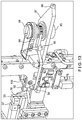
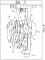
- This design has a similar cam structure 66 as illustrated in Figure 8 and is based on the use of torsion springs 92 to pivotably mount plate 94 onto plate 96, wherein rollers 95 are mounted on plate 94 are biased against cam structure 66 by the force of torsion springs 92, rather than the spring-loaded flexure 70 of Figure 8 , to provide substantially improved life.
- the ramp and pocket geometry is implemented by cam structure 66 and pocket 72, wherein pocket 72 can capture one of rollers 95.
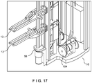
- Figure 17 is a perspective view of the opening bar system of the second embodiment of this disclosure.
- the rotating bar or opening bar 60 is supported on top and bottom by respective upper and lower pivots or bearings 82, 84 as shown in Figures 18a and 18b thereby allowing it to rotate along its length.
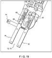
- the aspect ratio of the rotating bar 60 enables the device to be clear of the arms of lower and upper arm mechanisms 12, 13 in the closed arm position of Figure 19 . This clearance is typically important as it eliminates friction between the opening bar 60 and the arms 16, 18 of the lower and upper arm mechanisms 12, 13, thereby enabling the arms to follow the test sample with minimal drag.
- the rotating bar mechanism is used to open and close two sets of hinged mechanical arms on a long travel extensometer.
- Figures 22-27 are further perspective views of the further embodiments of the present disclosure. These embodiments include a device to mitigate debris from entering the device by the use of a constant force spring acting as a roll-up shade-type configuration and an improved way to repeatably adjust the tension of the spring that controls the amount of force the contacting arms puts on the specimen.
- the tensioner assembly shown on Figures 24-26 , includes knob 209 with markings which controls the extension of spring 211, which draws arms 214, 215 together.
- One end of spring 211 is held captive to arm 215 by means of a swiveling anchor, thereby allowing the spring to rotate freely on that end.
- the spring is held captive to arm 214 by being attached to threaded knob 209.
- Knob 209 is threaded against a threaded sleeve 208 that is fixed on to arm 214. As knob 209 is rotated, it changes the length of extension spring 211, altering the force with which spring 211 pulls the contacting arms 214, 215 together.
- knob 209 As knob 209 is rotated along the threads, more or less of knob 209 is exposed from beneath threaded sleeve 208.
- the amount of knob 209 exposed can be quantified by markings on knob 209.
- a user can rotate knob 209 to a desired contacting force setting and use the exposed markings on it as reference to achieve the same contacting force in future tests.
- FIGS 22-24 and 27 show the debris shield assemblies.
- Spring 200 is fed along channels on bilateral extrusions 203 and attached to a bracket 204 by means of a clamp 212.
- Bracket 204 is secured onto extrusion 203 using slide 207 on the opposite side. These two parts are clamped together with knob 206.
- Indicator plate 205 covers slide 207.
- the travel limit assemblies can slide vertically along features on extrusion 203 until the desired location. The user then tightens knob 206 and the vertical location becomes fixed.
- the extensometer design makes use of travel limits to protect the arms assemblies from damage by running into fixed objects in the test setup.
- the apparatus makes use of these travel limit assemblies to uncoil and recoil the constant force spring covering up gaps between extrusions 203 on positions the contacting arms will not use during a test.
- the open area of the extensometer is minimized and can thus mitigate the amount of debris from broken specimens and other environmental contaminants from finding their way into the extensometer.
- Element 216 shows areas covered by the debris shield assembly and element 217 shows exposed areas open to the inside of the extensometer. As the user sets the limits of travel, the apparatus automatically covers up unused areas with a low-cost design.
- the instrument will benefit from the inherent protection the mechanism gets by being inside the instrument. Specimen breaks can be very violent, dusty, and can send sections of specimens as projectiles. Also, any noise produced by the mechanism is muffled by being inside. The look of the instrument becomes cleaner and sleeker. Finally, this mechanism is less expensive, as there is no need for external covers or cosmetic consideration.
- the resulting apparatus typically achieves several advantages. If using an external rotating bar to actuate the arms, redesigned arms would be required to develop a longer-reach variant extensometer, an expensive and difficult technical task considered a sub-project on its own. With this disclosure, the arms typically do not change. Typically only the simple piece connecting the arms to the carriage needs to grow along with the length of the simple metal belt. This advantage is in addition to the aforementioned gain in reach by removing the mechanism itself. Together, this disclosure improves feasible arm reach while keeping development and part costs low.
Landscapes
- Physics & Mathematics (AREA)
- General Physics & Mathematics (AREA)
- General Engineering & Computer Science (AREA)
- Engineering & Computer Science (AREA)
- Biochemistry (AREA)
- Analytical Chemistry (AREA)
- Chemical & Material Sciences (AREA)
- General Health & Medical Sciences (AREA)
- Immunology (AREA)
- Pathology (AREA)
- Life Sciences & Earth Sciences (AREA)
- Health & Medical Sciences (AREA)
- Mechanical Engineering (AREA)
- Investigating Strength Of Materials By Application Of Mechanical Stress (AREA)
- A Measuring Device Byusing Mechanical Method (AREA)
Description
- The present disclosure relates to an extensometer wherein the actuation of the arms is performed by a separate rotating bar.
- An extensometer is an instrument that very accurately measures the extension of a test specimen in order to better capture the material properties of the specimen. A common extensometer is of the contacting type, which physically tracks two points in the specimen as the test takes place. These contacting points are typically in the form of arms that reach from the main body of the extensometer to the specimen location.
- For automatic contacting extensometers, it is necessary to have a means to make the contacting arms attach to and detach from the test specimen. Existing products make use of actuators, usually electric motors that are mounted to each of the two moving arms.
- During a test, the load cell on a test frame measures the force that is applied to the specimen. Since the arms are contacting the specimen, the load cell output will include not just the force applied to the specimen but also the additional force required to move the contacting arms. The force required to move these arms is called the running force. The running force also causes the contacting arms to deflect, causing errors in the extensometer readings. For these reasons, minimizing the running force is crucial to load output accuracy and extension accuracy.
- The idea of an external bar being used to remotely actuate the arms has been used before in an extensometer, notably the MFL by Mess & Feinwerktechnik (MF) shown on
Figure 1 . The device inFigure 1 does not use a linear encoder to measure the displacement of the arms. - The actuation method employed in
Figure 1 is based on the use of two eccentrically-mounted shafts that operate in a cam-action as shown inFigure 2 . Driven from a common actuator shown inFigure 3 , the cam bars move synchronously until the high point rotates into contact with a tab on each arm of the arm pair, forcing the arms open as shown inFigure 4 . - Another prior art approach is to have a system where sensitive strain gauges are attached to the ends of the arms. The device then lets the strain gauges track the displacement of the specimen until the end of the very limited travel of the strain gauges is about to be reached, at which point the instrument uses actuators to move the arms in the direction of specimen elongation to provide slack and allow more strain gauge travel. As a result, this architecture is immune to increased friction. The arm location is driven by motors even during testing, and not by the specimen itself.
- A remote arm actuation for extensometer is known from
CN 201 740 701 U . - A further example of extensometer is shown in
US 2 085 687 A . - The objective according to the invention is achieved by an extensometer comprising the features of claim 1. The dependent claims further develop the idea of the present invention.
- The disclosure allows the actuation of the arms to be removed from the arms by use of a separate rotating bar so as to avoid or minimize placing active mechanics onto the arms. The disclosure overcomes many challenges and successfully packages the mechanism fully inside the instrument, resulting in many advantages. Many of the typical advantages are the result of implementing the rotating bar inside the unit, with a unique method of transferring the rotational motion of the bar located in the back of the extensometer, yet actuating the arms which are located in front and outside of the instrument.
- Further objects and advantages of the disclosure will become apparent from the following description and from the accompanying drawings, wherein:
-
Figures 1-4 are illustrations of the prior art. -
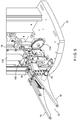
Figure 5 is perspective view of the rotating bar mechanism on the lower arm of a first embodiment of the present disclosure. -
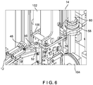
Figure 6 is a perspective view of the arm actuation mechanism of a first embodiment of the present disclosure. -
Figure 7 is a top cross-sectional view of the arm actuation mechanism of the first embodiment of the present disclosure. -
Figure 8 is a perspective view of a portion of the mechanism of the first embodiment of the present disclosure. -
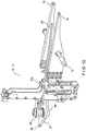
Figures 9a and 9b are side perspective and top plan views of a mechanism of the first embodiment of the present disclosure, for limiting angular displacement. -
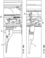
Figures 10a and 10b are side plan views of a mechanism the first embodiment of the present disclosure for eliminating bar contact during carriage travel. -
Figure 11 is a perspective view of the first embodiment of the present disclosure. -
Figures 12-14 are additional views of alternative mechanisms of the first embodiment of the present disclosure. -
Figures 15 and16 are perspective views of a mechanism that holds the angular position of the rotating spool. -
Figure 17 is a perspective view of the opening bar system of a second embodiment of the present disclosure. -
Figures 18a and 18b are top and bottom views, respectively, of the rotating bar pivot points of a second embodiment of the present disclosure. -
Figure 19 is a perspective view of the arms in the closed position in the second embodiment of the present disclosure. -
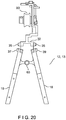
Figure 20 is a perspective view of the arms in the open position in response to the rotation of the bar in the second embodiment of the present disclosure. -
Figure 21 is a perspective view of a sliding roller in the second embodiment of the present disclosure. -
Figures 22-27 are further perspective views of the further embodiments of the present disclosure. - Referring now to the drawings in detail wherein like numerals indicate like elements throughout the several views, one sees that
Figure 1 , while prior art, illustrates the general structure of anextensometer 1000. Theextensometer 1000 includes anupper arm assembly 1002 and alower arm assembly 1004 which are vertically aligned with each other along avertical track 1006.Upper arm assembly 1002 includes two horizontally opposed contactingarms lower arm assembly 1004 includes two horizontally opposed contactingarms Figure 1 does not use a linear encoder to measure the displacement of the arms. -
Figures 2-4 show the details of thearm assemblies vertical track 1006 of the prior art embodiment ofFigure 1 . -
Figures 5-7 are perspective views thelower arm mechanism 12 and associatedrotating bar mechanism 14 of an embodiment of theextensometer 10 of the present disclosure.Lower arm mechanism 12 is mounted on acarriage 100 which rides onvertical tracks 102 in response topulley mechanism 104.Lower arm mechanism 12 further includes firstlower contacting arm 16 and second lower contactingarm 18 which can be urged together in a gripping configuration by contactforce adjustment assembly 19, which may be manually operated. As best shown inFigure 7 , first andsecond lever arms distal ends arms lower lever arms central pivot points cross-support member 32. First andsecond ends cross-support member 32 provide a resilient flexible mount for theproximal ends arms lower lever arms proximal ends boss roller elements boss roller elements inclined guide slots wedge 46. Wedge 46 is biased bycompression spring 48, mounted between first and secondproximal ends proximal ends wedge 46 in the left-hand direction of the orientation of the illustration inFigure 7 . Whencompression spring 48 urges thewedge 46 to a more left-hand position than shown inFigure 7 , the first andsecond roller elements guide slots second lever arms arms -
Wedge 46 is further attached to metal belt 50 (which may be implemented as a thin stainless steel shim), which is guided byrollers spool 58 which is mounted on rotatingbar 60. Rotatingbar 60 goes through the arm assemblies inside of the extensometer. Whenbar 60 rotates, it winds themetal belt 50 aroundspool 58, thereby pullingwedge 46 to the right-most position inFigure 7 (acting against the force of compression spring 48), thereby urging the first andsecond roller elements arms bar 60, but rather by the motion of themetal belt 50. As thebar 60 rotates clockwise, thespool 58 coils up themetal belt 50 and it in turn goes around the main structure of theextensometer 10 by means ofrollers wedge 46 and causes the motions as described above. By way ofcompression spring 48 urging first and second proximal ends 34, 36 apart, theextensometer 10 works in the opposite way and returns to its closed position when the motor rotatesbar 60 counter-clockwise. A singlerotating bar 60 is provided for theextensometer 10, with aseparate spool 58 provided onbar 60 for each of the lower andupper arm assemblies upper arm assemblies -
Figure 7 further illustrates how the first embodiment of the present disclosure prevents contact with the rotatingbar 60 during arm carriage motion. In an encoder-based extensometer architecture, having a rotating bar actuate the arms to open and close creates a substantial obstacle in that thebar 60 must stop making contact after opening and after closing. The requirement comes as a result of the added friction on the arm assemblies due to thebar 60 making contact with the rolling assemblies to which the arms are attached. An objective in a contacting extensometer may be the goal of making the complete arm subassembly carriage have reduced or eliminated running forces due to weight which impinge upon critical elements (i.e., sometimes referred to by those skilled in the art as being "weightless"). The arm carriages typically would have to be precisely counter-balanced and significant effort must be invested in keeping rolling surfaces as frictionless as possible. This is typically difficult to accomplish in order to maintain accuracy that having the bar making contact during testing is typically not practically feasible. The added friction would deflect the contacting arms and the forces required to move the carriages would typically both be expected to produce large errors. - As a result, a mechanism is provided to back-drive the
bar 60 from its open or closed angular position to a free position where there is no contact with thespool 58, which is mounted on spool bearing 85 onbase plate 87. As shown onFigure 8 , a vertically camming bearingprofile 66 is provided along the outer edge ofspool 58, upon whichsmall bearing 68 rides. Thebearing 68 is attached to a spring-loaded flexure 70 (which may be provided by a torsion spring assembly) that always ensures downward preloading. The vertically camming bearingprofile 66 upon which thebearing 68 rides has apocket 72 to capture or to detent engage bearing 68 in the lower closed position, and another in the upper open position (not shown). The upper open position may also be implemented with a stop pin rather than a pocket, because spring-loadedflexure 70 forces in the arms to bias the mechanism towards this position. The force of the spring-loadedflexure 70 also typically requires a precise shaping of vertically camming bearingprofile 66, as opposed to a horizontal surface which may cause the first and second contactingarms carriage 100 includes abearing 99 for riding intrack 101. - In order to improve the performance of the vertically camming bearing profile, the motor typically must be controlled in such a way as to know when to stop turning and reverse direction, and when to stop the reverse motion and position itself in the free range. In other words, angular displacement must be limited so that the range of rotation of the rotating
bar 60 is controlled. As shown onFigure 9a , in order to minimize or reduce expensive motion control, at the top of thebar 60 there is aflat wedge 76 withradial edges 78, 80 (i.e., pie-shaped or partially circular) that cross the path of a fixedoptical switch 81 as it rotates with thebar 60. The radial edges 78, 80 break the optical signal and trigger the motor to stop or reverse, in effect acting as a rotary encoder. This not only typically rotationally positions thebar 60 to be in an accurate and repeatable stop in the contact-free zone, but also stops the motor reverse direction at a precise point without over-torqueing the carriage assemblies.Figure 9b shows a top view of the mechanism with thebar 60 in the middle of the contact-free position. -
Figures 10a and 10b illustrate the advantages of moving the bar inside, to the back of theextensometer 10. An objective of anextensometer 10 may be to reach over a set of grips or other similar devices holding a specimen. As such, the amount of reach of the contacting arms is absolutely necessary for the instrument to be compatible with larger grips. There are, however, practical limitations as to how far arms can reach. The distance from the contacting point of the arms to the point where the measurement is made inside is incredibly sensitive to minute deflections, bearing surface imperfections, and increases in drag. Consequently, maximizing the amount of that distance devoted to actual test reach is crucial. This, in effect, means that any distance forward of the measurement encoder not free to clear grips is lost reach. Placing the mechanism at the back means zero reach lost to the actuation mechanism. For reference, note the difference in reach from an earlier concept using an external bar onFigure 10a versus the internal bar onFigure 10b . In an embodiment of the disclosure illustrated inFigure 10b , over 65 millimeters of additional reach resulted from the internal packaging of the bar at the rear of the extensometer, as compared to the extensometer ofFigure 10a . -
Figure 11 is a perspective view of an embodiment ofextensometer 10, includinglower arm mechanism 12 and upper arm mechanism 13 (with substantially the same structure aslower arm mechanism 12, but typically inverted) whileFigures 12-14 include further alternative variations of the disclosure. -
Figures 15 and16 pertain to a mechanism of the spool bearing 85, mounted onbase plate 87 ofcarriage 100, that holds the angular position of therotating spool 58 to prevent contact with thebar 60. This design has asimilar cam structure 66 as illustrated inFigure 8 and is based on the use of torsion springs 92 to pivotablymount plate 94 ontoplate 96, whereinrollers 95 are mounted onplate 94 are biased againstcam structure 66 by the force of torsion springs 92, rather than the spring-loadedflexure 70 ofFigure 8 , to provide substantially improved life. The ramp and pocket geometry is implemented bycam structure 66 andpocket 72, whereinpocket 72 can capture one ofrollers 95. - The second embodiment of the disclosure is illustrated in
Figures 17-21 .Figure 17 is a perspective view of the opening bar system of the second embodiment of this disclosure. In this second embodiment, the rotating bar or openingbar 60 is supported on top and bottom by respective upper and lower pivots orbearings Figures 18a and 18b thereby allowing it to rotate along its length. The aspect ratio of the rotatingbar 60 enables the device to be clear of the arms of lower andupper arm mechanisms Figure 19 . This clearance is typically important as it eliminates friction between the openingbar 60 and thearms upper arm mechanisms bar 60 is rotated so that its wider dimension is transverse between thearms arms bar 60 engage with the spring-loaded slidingrollers 86, 87 (which are freely rotating and traverse a longitudinal portion ofarms 16, 18) thereby reducing the friction between the openingbar 60 and thearms arms bar 60 as illustrated inFigures 20 and21 . The openingbar 60 can be motor driven or manually operated. Thearms vertical rollers 90 illustrated inFigure 21 allow the lower andupper arm mechanisms -
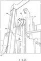
Figures 22-27 are further perspective views of the further embodiments of the present disclosure. These embodiments include a device to mitigate debris from entering the device by the use of a constant force spring acting as a roll-up shade-type configuration and an improved way to repeatably adjust the tension of the spring that controls the amount of force the contacting arms puts on the specimen. - The tensioner assembly, shown on
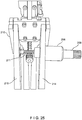
Figures 24-26 , includesknob 209 with markings which controls the extension ofspring 211, which drawsarms spring 211 is held captive toarm 215 by means of a swiveling anchor, thereby allowing the spring to rotate freely on that end. At the other end ofspring 211, the spring is held captive toarm 214 by being attached to threadedknob 209.Knob 209 is threaded against a threadedsleeve 208 that is fixed on toarm 214. Asknob 209 is rotated, it changes the length ofextension spring 211, altering the force with which spring 211 pulls the contactingarms knob 209 is rotated along the threads, more or less ofknob 209 is exposed from beneath threadedsleeve 208. The amount ofknob 209 exposed can be quantified by markings onknob 209. As a result, a user can rotateknob 209 to a desired contacting force setting and use the exposed markings on it as reference to achieve the same contacting force in future tests. -
Figures 22-24 and27 show the debris shield assemblies. There are two debris shield assemblies (upper and lower, mirrored) including a constant-force-spring 200 coiled around aspool assembly 202.Spring 200 is fed along channels onbilateral extrusions 203 and attached to abracket 204 by means of aclamp 212.Bracket 204 is secured ontoextrusion 203 usingslide 207 on the opposite side. These two parts are clamped together withknob 206.Indicator plate 205 coversslide 207. The travel limit assemblies can slide vertically along features onextrusion 203 until the desired location. The user then tightensknob 206 and the vertical location becomes fixed. The extensometer design makes use of travel limits to protect the arms assemblies from damage by running into fixed objects in the test setup. The apparatus makes use of these travel limit assemblies to uncoil and recoil the constant force spring covering up gaps betweenextrusions 203 on positions the contacting arms will not use during a test. As a result, the open area of the extensometer is minimized and can thus mitigate the amount of debris from broken specimens and other environmental contaminants from finding their way into the extensometer.Element 216 shows areas covered by the debris shield assembly andelement 217 shows exposed areas open to the inside of the extensometer. As the user sets the limits of travel, the apparatus automatically covers up unused areas with a low-cost design. - In conclusion, the instrument will benefit from the inherent protection the mechanism gets by being inside the instrument. Specimen breaks can be very violent, dusty, and can send sections of specimens as projectiles. Also, any noise produced by the mechanism is muffled by being inside. The look of the instrument becomes cleaner and sleeker. Finally, this mechanism is less expensive, as there is no need for external covers or cosmetic consideration.
- The resulting apparatus typically achieves several advantages. If using an external rotating bar to actuate the arms, redesigned arms would be required to develop a longer-reach variant extensometer, an expensive and difficult technical task considered a sub-project on its own. With this disclosure, the arms typically do not change. Typically only the simple piece connecting the arms to the carriage needs to grow along with the length of the simple metal belt. This advantage is in addition to the aforementioned gain in reach by removing the mechanism itself. Together, this disclosure improves feasible arm reach while keeping development and part costs low.
- Similarly, there is a growing need in the marketplace to use extensometers in high-temperature applications. By removing the actuating mechanism form the front of the instrument and being able to extend just one part with a thin cross section to gain additional reach, this product will readily be able to be configured for use in high-temperature chambers inside of which the arms must fully reside. The design can be easily adapted to only have high temperature-safe materials where required and the chamber opening can remain small.
- Thus the several aforementioned objects and advantages are most effectively attained. Although preferred embodiments of the invention have been disclosed and described in detail herein, it should be understood that this invention is in no sense limited thereby and its scope is to be determined by that of the appended claims.
Claims (10)
- An extensometer including:a first arm assembly (12) and a second arm assembly (13), each arm assembly including first and second reciprocating contact arms (16, 18);the first and second arm assemblies (12, 13) each including:a camming element (46), each camming element including first and second inclined camming slots (42, 44), which are inclined with respect to each other,a first lever arm (20) with a first proximal end (34) engaged within the first inclined camming slot (42) and a first distal end (24) engaged with the first contacting arm (16), and a first pivot point (28) between the first proximal end (34) and the first distal end (24);a second lever arm (22) with a second proximal end (36) engaged within the second inclined camming slot (44) and a second distal end (26) engaged with the second contacting arm (18), and a second pivot point (30) between the second proximal end (36) and the second distal end (26);a support member (32) upon which the first and second pivot points (38, 30) are pivotably mounted;wherein when the camming element (46) is in a first position, the first and second contact arms (16, 18) are urged toward each other and wherein when the camming element (46) is in a second position, the first and second contact arms (16, 18) are urged away from each other; anda drive mechanism configured to urge the camming element (46) from the first position to the second position, the drive mechanism being separated from the camming element; said extensometer further comprising a vertical track structure (102) upon which the first and second arm assemblies (12, 13) are configured to travel.
- The extensometer of Claim 1 wherein each support member (32) includes a first end (33) to which a proximal end (37) of the first contact arm (16) is resiliently flexibly mounted, and a second end (35) to which a proximal end (39) of the second contact arm (18) is resiliently flexibly mounted.
- The extensometer of Claim 2 wherein the camming element is a wedge (46) with said first and second inclined camming slots (42, 44), and wherein the first and second proximal ends (34, 36) of the respective first and second lever arms (20, 22) include respective first and second boss roller elements (38, 40) which are engaged so as to travel within the respective first and second inclined camming slots (42, 44).
- The extensometer of Claim 3 wherein the first and second arm assemblies (12, 13) each include a spring (48) for biasing the camming element (46) toward the first position.
- The extensometer of Claim 4 wherein the drive mechanism includes a rotating element (60) which rotates a spool (58), and wherein the extensometer further includes a belt (50) with a first end attached to the camming element (46) and a second end attached the spool (58), whereby when the rotating element (60) is rotated, the spool (58) rotates, thereby pulling the belt (50) and urging the camming element (46) from the first position to the second position.
- The extensometer of Claim 1 wherein the first and second contact arms (16, 18) of the first and second arm assemblies (12, 13) are on a first side of the track structure (102) and the rotating element (60) is on the other side of the track structure.
- The extensometer of Claim 6 wherein the rotating element is a rotating bar (60), and wherein the rotating bar is attached to an element with edges (78 80) which move in response to rotation of the rotating bar (60) and operate a switch (81) to indicate the desired range of motion of the rotating bar.
- The extensometer of Claim 7 wherein the element (60) includes radially oriented edges and wherein the switch (81) is an optical switch.
- The extensometer of Claim 8 wherein the spool (58) is mounted on a spool bearing (85), the spool bearing including a cammed surface with at least one pocket (72), and wherein the extensometer further includes a spring-loaded mechanism for engaging the at least one pocket (72) thereby maintaining an angular orientation of the spool (58).
- The extensometer of Claim 5 wherein the belt (50) is mounted on at least one roller (52, 54, 56) so that the belt passes from the first side to the second side of the vertical track structure (102).
Applications Claiming Priority (2)
| Application Number | Priority Date | Filing Date | Title |
|---|---|---|---|
| US201261697624P | 2012-09-06 | 2012-09-06 | |
| PCT/US2013/058337 WO2014039728A1 (en) | 2012-09-06 | 2013-09-05 | Extensometer remote arm actuation |
Publications (2)
| Publication Number | Publication Date |
|---|---|
| EP2893292A1 EP2893292A1 (en) | 2015-07-15 |
| EP2893292B1 true EP2893292B1 (en) | 2018-02-07 |
Family
ID=49182529
Family Applications (1)
| Application Number | Title | Priority Date | Filing Date |
|---|---|---|---|
| EP13762968.9A Active EP2893292B1 (en) | 2012-09-06 | 2013-09-05 | Extensometer remote arm actuation |
Country Status (4)
| Country | Link |
|---|---|
| US (1) | US9551560B2 (en) |
| EP (1) | EP2893292B1 (en) |
| CN (1) | CN104487797B (en) |
| WO (1) | WO2014039728A1 (en) |
Families Citing this family (8)
| Publication number | Priority date | Publication date | Assignee | Title |
|---|---|---|---|---|
| CN106537081B (en) * | 2014-08-07 | 2020-12-01 | 伊利诺斯工具制品有限公司 | Automatic Lateral Strain Extensometer Architecture |
| CN104359392B (en) * | 2014-11-10 | 2016-10-26 | 中国船舶重工集团公司第七○二研究所 | Rod-pulling type submerged structure deformation measuring device |
| CN105043863B (en) * | 2014-12-26 | 2018-04-10 | 高铁检测仪器(东莞)有限公司 | Semi-automatic point marking extensometer |
| JP6260562B2 (en) * | 2015-03-20 | 2018-01-17 | 株式会社島津製作所 | Displacement measuring device and material testing machine |
| CN105444727A (en) * | 2015-11-16 | 2016-03-30 | 武汉大学 | Measuring range adjusting device of electronic extensometer |
| JP6767049B2 (en) * | 2016-12-22 | 2020-10-14 | 株式会社インテスコ | Inter-marker elongation measuring device and inter-marker elongation measuring system including the device |
| CN111623744A (en) * | 2020-05-14 | 2020-09-04 | 湖北恒义智能科技有限公司 | A Surface Topography Acquisition and Measurement System |
| US11650039B1 (en) * | 2020-06-04 | 2023-05-16 | Julieta Kevorkian Hughes | Head-measuring device |
Family Cites Families (15)
| Publication number | Priority date | Publication date | Assignee | Title |
|---|---|---|---|---|
| US2085687A (en) * | 1933-01-11 | 1937-06-29 | Baldwin Southwark Corp | Extensometer |
| US2663085A (en) * | 1951-12-01 | 1953-12-22 | Baldwin Lima Hamilton Corp | Extensometer |
| US2827705A (en) * | 1954-05-12 | 1958-03-25 | United Shoe Machinery Corp | Apparatus for use in tensile testing |
| US4315372A (en) * | 1980-04-17 | 1982-02-16 | Fitness Motivation Institute Of America | Caliper for applying constant pressure to an object being measured |
| JPH0797070B2 (en) | 1984-11-29 | 1995-10-18 | 株式会社島津製作所 | Extensometer |
| US4823473A (en) * | 1986-09-19 | 1989-04-25 | Instron Corporation | Extensometer for material testing machine |
| CA1282259C (en) * | 1986-12-22 | 1991-04-02 | John Van Der Kuur | Extensometer |
| CN2116899U (en) * | 1992-03-11 | 1992-09-23 | 自贡市计量测试研究所 | Distance-changed join leading meter |
| CN2164015Y (en) * | 1993-08-01 | 1994-05-04 | 机械工业部长春试验机研究所 | Resistance strain gauge type stretching gauge |
| US5819428A (en) * | 1996-08-19 | 1998-10-13 | Mts Systems Corporation | Extensometer structure |
| US5899910A (en) * | 1996-09-17 | 1999-05-04 | Etman; Sameer A. | Direct acting cam gripping mechanism |
| JP2000234904A (en) * | 1999-02-12 | 2000-08-29 | Shimadzu Corp | Extensometer |
| US6910402B2 (en) * | 2003-08-13 | 2005-06-28 | National-Oilwell, L. P. | Pipe spinner |
| CN201096687Y (en) * | 2007-10-31 | 2008-08-06 | 刘莫峣 | Compressed average flexing meter |
| CN201740701U (en) * | 2010-07-23 | 2011-02-09 | 济南试金集团有限公司 | Automatic extensometer |
-
2013
- 2013-09-05 EP EP13762968.9A patent/EP2893292B1/en active Active
- 2013-09-05 CN CN201380036221.8A patent/CN104487797B/en active Active
- 2013-09-05 WO PCT/US2013/058337 patent/WO2014039728A1/en not_active Ceased
- 2013-09-05 US US14/424,484 patent/US9551560B2/en active Active
Also Published As
| Publication number | Publication date |
|---|---|
| WO2014039728A1 (en) | 2014-03-13 |
| EP2893292A1 (en) | 2015-07-15 |
| US20150204646A1 (en) | 2015-07-23 |
| CN104487797B (en) | 2017-06-16 |
| CN104487797A (en) | 2015-04-01 |
| US9551560B2 (en) | 2017-01-24 |
Similar Documents
| Publication | Publication Date | Title |
|---|---|---|
| US9551560B2 (en) | Extensometer remote arm actuation | |
| EP1180662B1 (en) | Position transducer | |
| US8254022B2 (en) | Sample positioning stage and method of operation | |
| JPS586882B2 (en) | extensometer | |
| CN108072352A (en) | A kind of shaft position sensor clamping device | |
| US20180112976A1 (en) | Mechanical strain extensometer | |
| CN106537081B (en) | Automatic Lateral Strain Extensometer Architecture | |
| US20110088481A1 (en) | Attachment displacement sensor for measuring the change in length of a sample and measuring method which uses such a sensor | |
| CN120333991B (en) | A tensile testing device for material testing | |
| JP2681243B2 (en) | Measuring device for dimensions and shapes of prismatic cylinders and prisms | |
| CN206816940U (en) | Position sensor of valve and intelligent positioner | |
| RU2016371C1 (en) | Device for measuring profiles of odd-shaped article cross sections | |
| CN113720512B (en) | Thrust detection device of electric actuating mechanism | |
| JPH10170208A (en) | Extensometer | |
| SU1441252A1 (en) | Device for measuring hardness | |
| SU600422A1 (en) | Adhesion meter for testing polymer coatings | |
| CN117782425A (en) | Torque wrench calibrating instrument | |
| SU1467373A1 (en) | Device for measuring sizes of inner surfaces of lengthy articles | |
| US8474323B1 (en) | Carpet deflection measurement device | |
| CN115200757A (en) | Measuring device for joint holding torque of support arm | |
| SU1733912A1 (en) | Contact spherometer | |
| RU73473U1 (en) | DEVICE FOR CONTROL OF MEASURING INSTRUMENTS, PREVIOUSLY OF CALIBERS-BRACKET | |
| CN117990511A (en) | A sample loading and testing device | |
| SU1682892A1 (en) | Material friction coefficient determining device | |
| SU807134A1 (en) | Device for determining mechanical properties of materials |
Legal Events
| Date | Code | Title | Description |
|---|---|---|---|
| PUAI | Public reference made under article 153(3) epc to a published international application that has entered the european phase |
Free format text: ORIGINAL CODE: 0009012 |
|
| 17P | Request for examination filed |
Effective date: 20141210 |
|
| AK | Designated contracting states |
Kind code of ref document: A1 Designated state(s): AL AT BE BG CH CY CZ DE DK EE ES FI FR GB GR HR HU IE IS IT LI LT LU LV MC MK MT NL NO PL PT RO RS SE SI SK SM TR |
|
| AX | Request for extension of the european patent |
Extension state: BA ME |
|
| DAX | Request for extension of the european patent (deleted) | ||
| GRAP | Despatch of communication of intention to grant a patent |
Free format text: ORIGINAL CODE: EPIDOSNIGR1 |
|
| INTG | Intention to grant announced |
Effective date: 20171006 |
|
| GRAS | Grant fee paid |
Free format text: ORIGINAL CODE: EPIDOSNIGR3 |
|
| GRAA | (expected) grant |
Free format text: ORIGINAL CODE: 0009210 |
|
| AK | Designated contracting states |
Kind code of ref document: B1 Designated state(s): AL AT BE BG CH CY CZ DE DK EE ES FI FR GB GR HR HU IE IS IT LI LT LU LV MC MK MT NL NO PL PT RO RS SE SI SK SM TR |
|
| REG | Reference to a national code |
Ref country code: GB Ref legal event code: FG4D |
|
| REG | Reference to a national code |
Ref country code: AT Ref legal event code: REF Ref document number: 968974 Country of ref document: AT Kind code of ref document: T Effective date: 20180215 Ref country code: CH Ref legal event code: EP |
|
| REG | Reference to a national code |
Ref country code: IE Ref legal event code: FG4D |
|
| REG | Reference to a national code |
Ref country code: DE Ref legal event code: R096 Ref document number: 602013032948 Country of ref document: DE |
|
| REG | Reference to a national code |
Ref country code: NL Ref legal event code: MP Effective date: 20180207 |
|
| REG | Reference to a national code |
Ref country code: AT Ref legal event code: MK05 Ref document number: 968974 Country of ref document: AT Kind code of ref document: T Effective date: 20180207 |
|
| PG25 | Lapsed in a contracting state [announced via postgrant information from national office to epo] |
Ref country code: FI Free format text: LAPSE BECAUSE OF FAILURE TO SUBMIT A TRANSLATION OF THE DESCRIPTION OR TO PAY THE FEE WITHIN THE PRESCRIBED TIME-LIMIT Effective date: 20180207 Ref country code: CY Free format text: LAPSE BECAUSE OF FAILURE TO SUBMIT A TRANSLATION OF THE DESCRIPTION OR TO PAY THE FEE WITHIN THE PRESCRIBED TIME-LIMIT Effective date: 20180207 Ref country code: NL Free format text: LAPSE BECAUSE OF FAILURE TO SUBMIT A TRANSLATION OF THE DESCRIPTION OR TO PAY THE FEE WITHIN THE PRESCRIBED TIME-LIMIT Effective date: 20180207 Ref country code: ES Free format text: LAPSE BECAUSE OF FAILURE TO SUBMIT A TRANSLATION OF THE DESCRIPTION OR TO PAY THE FEE WITHIN THE PRESCRIBED TIME-LIMIT Effective date: 20180207 Ref country code: LT Free format text: LAPSE BECAUSE OF FAILURE TO SUBMIT A TRANSLATION OF THE DESCRIPTION OR TO PAY THE FEE WITHIN THE PRESCRIBED TIME-LIMIT Effective date: 20180207 Ref country code: HR Free format text: LAPSE BECAUSE OF FAILURE TO SUBMIT A TRANSLATION OF THE DESCRIPTION OR TO PAY THE FEE WITHIN THE PRESCRIBED TIME-LIMIT Effective date: 20180207 Ref country code: NO Free format text: LAPSE BECAUSE OF FAILURE TO SUBMIT A TRANSLATION OF THE DESCRIPTION OR TO PAY THE FEE WITHIN THE PRESCRIBED TIME-LIMIT Effective date: 20180507 |
|
| PG25 | Lapsed in a contracting state [announced via postgrant information from national office to epo] |
Ref country code: BG Free format text: LAPSE BECAUSE OF FAILURE TO SUBMIT A TRANSLATION OF THE DESCRIPTION OR TO PAY THE FEE WITHIN THE PRESCRIBED TIME-LIMIT Effective date: 20180507 Ref country code: RS Free format text: LAPSE BECAUSE OF FAILURE TO SUBMIT A TRANSLATION OF THE DESCRIPTION OR TO PAY THE FEE WITHIN THE PRESCRIBED TIME-LIMIT Effective date: 20180207 Ref country code: AT Free format text: LAPSE BECAUSE OF FAILURE TO SUBMIT A TRANSLATION OF THE DESCRIPTION OR TO PAY THE FEE WITHIN THE PRESCRIBED TIME-LIMIT Effective date: 20180207 Ref country code: PL Free format text: LAPSE BECAUSE OF FAILURE TO SUBMIT A TRANSLATION OF THE DESCRIPTION OR TO PAY THE FEE WITHIN THE PRESCRIBED TIME-LIMIT Effective date: 20180207 Ref country code: SE Free format text: LAPSE BECAUSE OF FAILURE TO SUBMIT A TRANSLATION OF THE DESCRIPTION OR TO PAY THE FEE WITHIN THE PRESCRIBED TIME-LIMIT Effective date: 20180207 Ref country code: IS Free format text: LAPSE BECAUSE OF FAILURE TO SUBMIT A TRANSLATION OF THE DESCRIPTION OR TO PAY THE FEE WITHIN THE PRESCRIBED TIME-LIMIT Effective date: 20180607 Ref country code: LV Free format text: LAPSE BECAUSE OF FAILURE TO SUBMIT A TRANSLATION OF THE DESCRIPTION OR TO PAY THE FEE WITHIN THE PRESCRIBED TIME-LIMIT Effective date: 20180207 Ref country code: GR Free format text: LAPSE BECAUSE OF FAILURE TO SUBMIT A TRANSLATION OF THE DESCRIPTION OR TO PAY THE FEE WITHIN THE PRESCRIBED TIME-LIMIT Effective date: 20180508 |
|
| PG25 | Lapsed in a contracting state [announced via postgrant information from national office to epo] |
Ref country code: EE Free format text: LAPSE BECAUSE OF FAILURE TO SUBMIT A TRANSLATION OF THE DESCRIPTION OR TO PAY THE FEE WITHIN THE PRESCRIBED TIME-LIMIT Effective date: 20180207 Ref country code: RO Free format text: LAPSE BECAUSE OF FAILURE TO SUBMIT A TRANSLATION OF THE DESCRIPTION OR TO PAY THE FEE WITHIN THE PRESCRIBED TIME-LIMIT Effective date: 20180207 Ref country code: IT Free format text: LAPSE BECAUSE OF FAILURE TO SUBMIT A TRANSLATION OF THE DESCRIPTION OR TO PAY THE FEE WITHIN THE PRESCRIBED TIME-LIMIT Effective date: 20180207 Ref country code: AL Free format text: LAPSE BECAUSE OF FAILURE TO SUBMIT A TRANSLATION OF THE DESCRIPTION OR TO PAY THE FEE WITHIN THE PRESCRIBED TIME-LIMIT Effective date: 20180207 |
|
| REG | Reference to a national code |
Ref country code: DE Ref legal event code: R097 Ref document number: 602013032948 Country of ref document: DE |
|
| PG25 | Lapsed in a contracting state [announced via postgrant information from national office to epo] |
Ref country code: DK Free format text: LAPSE BECAUSE OF FAILURE TO SUBMIT A TRANSLATION OF THE DESCRIPTION OR TO PAY THE FEE WITHIN THE PRESCRIBED TIME-LIMIT Effective date: 20180207 Ref country code: SM Free format text: LAPSE BECAUSE OF FAILURE TO SUBMIT A TRANSLATION OF THE DESCRIPTION OR TO PAY THE FEE WITHIN THE PRESCRIBED TIME-LIMIT Effective date: 20180207 Ref country code: SK Free format text: LAPSE BECAUSE OF FAILURE TO SUBMIT A TRANSLATION OF THE DESCRIPTION OR TO PAY THE FEE WITHIN THE PRESCRIBED TIME-LIMIT Effective date: 20180207 Ref country code: CZ Free format text: LAPSE BECAUSE OF FAILURE TO SUBMIT A TRANSLATION OF THE DESCRIPTION OR TO PAY THE FEE WITHIN THE PRESCRIBED TIME-LIMIT Effective date: 20180207 |
|
| PLBE | No opposition filed within time limit |
Free format text: ORIGINAL CODE: 0009261 |
|
| STAA | Information on the status of an ep patent application or granted ep patent |
Free format text: STATUS: NO OPPOSITION FILED WITHIN TIME LIMIT |
|
| 26N | No opposition filed |
Effective date: 20181108 |
|
| PG25 | Lapsed in a contracting state [announced via postgrant information from national office to epo] |
Ref country code: SI Free format text: LAPSE BECAUSE OF FAILURE TO SUBMIT A TRANSLATION OF THE DESCRIPTION OR TO PAY THE FEE WITHIN THE PRESCRIBED TIME-LIMIT Effective date: 20180207 |
|
| PG25 | Lapsed in a contracting state [announced via postgrant information from national office to epo] |
Ref country code: MC Free format text: LAPSE BECAUSE OF FAILURE TO SUBMIT A TRANSLATION OF THE DESCRIPTION OR TO PAY THE FEE WITHIN THE PRESCRIBED TIME-LIMIT Effective date: 20180207 |
|
| REG | Reference to a national code |
Ref country code: CH Ref legal event code: PL |
|
| REG | Reference to a national code |
Ref country code: BE Ref legal event code: MM Effective date: 20180930 |
|
| REG | Reference to a national code |
Ref country code: IE Ref legal event code: MM4A |
|
| PG25 | Lapsed in a contracting state [announced via postgrant information from national office to epo] |
Ref country code: LU Free format text: LAPSE BECAUSE OF NON-PAYMENT OF DUE FEES Effective date: 20180905 |
|
| PG25 | Lapsed in a contracting state [announced via postgrant information from national office to epo] |
Ref country code: IE Free format text: LAPSE BECAUSE OF NON-PAYMENT OF DUE FEES Effective date: 20180905 |
|
| PG25 | Lapsed in a contracting state [announced via postgrant information from national office to epo] |
Ref country code: FR Free format text: LAPSE BECAUSE OF NON-PAYMENT OF DUE FEES Effective date: 20180930 Ref country code: BE Free format text: LAPSE BECAUSE OF NON-PAYMENT OF DUE FEES Effective date: 20180930 Ref country code: LI Free format text: LAPSE BECAUSE OF NON-PAYMENT OF DUE FEES Effective date: 20180930 Ref country code: CH Free format text: LAPSE BECAUSE OF NON-PAYMENT OF DUE FEES Effective date: 20180930 |
|
| PG25 | Lapsed in a contracting state [announced via postgrant information from national office to epo] |
Ref country code: MT Free format text: LAPSE BECAUSE OF NON-PAYMENT OF DUE FEES Effective date: 20180905 |
|
| PG25 | Lapsed in a contracting state [announced via postgrant information from national office to epo] |
Ref country code: TR Free format text: LAPSE BECAUSE OF FAILURE TO SUBMIT A TRANSLATION OF THE DESCRIPTION OR TO PAY THE FEE WITHIN THE PRESCRIBED TIME-LIMIT Effective date: 20180207 |
|
| PG25 | Lapsed in a contracting state [announced via postgrant information from national office to epo] |
Ref country code: PT Free format text: LAPSE BECAUSE OF FAILURE TO SUBMIT A TRANSLATION OF THE DESCRIPTION OR TO PAY THE FEE WITHIN THE PRESCRIBED TIME-LIMIT Effective date: 20180207 |
|
| PG25 | Lapsed in a contracting state [announced via postgrant information from national office to epo] |
Ref country code: HU Free format text: LAPSE BECAUSE OF FAILURE TO SUBMIT A TRANSLATION OF THE DESCRIPTION OR TO PAY THE FEE WITHIN THE PRESCRIBED TIME-LIMIT; INVALID AB INITIO Effective date: 20130905 Ref country code: MK Free format text: LAPSE BECAUSE OF NON-PAYMENT OF DUE FEES Effective date: 20180207 |
|
| P01 | Opt-out of the competence of the unified patent court (upc) registered |
Effective date: 20230606 |
|
| PGFP | Annual fee paid to national office [announced via postgrant information from national office to epo] |
Ref country code: DE Payment date: 20250929 Year of fee payment: 13 |
|
| PGFP | Annual fee paid to national office [announced via postgrant information from national office to epo] |
Ref country code: GB Payment date: 20250929 Year of fee payment: 13 |