EP2893289B1 - Distributed ordnance system, multiple stage ordnance system, and related methods - Google Patents
Distributed ordnance system, multiple stage ordnance system, and related methods Download PDFInfo
- Publication number
- EP2893289B1 EP2893289B1 EP13840177.3A EP13840177A EP2893289B1 EP 2893289 B1 EP2893289 B1 EP 2893289B1 EP 13840177 A EP13840177 A EP 13840177A EP 2893289 B1 EP2893289 B1 EP 2893289B1
- Authority
- EP
- European Patent Office
- Prior art keywords
- ordnance
- stage
- controller
- controllers
- firing unit
- Prior art date
- Legal status (The legal status is an assumption and is not a legal conclusion. Google has not performed a legal analysis and makes no representation as to the accuracy of the status listed.)
- Active
Links
Images


Classifications
-
- F—MECHANICAL ENGINEERING; LIGHTING; HEATING; WEAPONS; BLASTING
- F42—AMMUNITION; BLASTING
- F42B—EXPLOSIVE CHARGES, e.g. FOR BLASTING, FIREWORKS, AMMUNITION
- F42B15/00—Self-propelled projectiles or missiles, e.g. rockets; Guided missiles
- F42B15/01—Arrangements thereon for guidance or control
-
- F—MECHANICAL ENGINEERING; LIGHTING; HEATING; WEAPONS; BLASTING
- F02—COMBUSTION ENGINES; HOT-GAS OR COMBUSTION-PRODUCT ENGINE PLANTS
- F02K—JET-PROPULSION PLANTS
- F02K9/00—Rocket-engine plants, i.e. plants carrying both fuel and oxidant therefor; Control thereof
- F02K9/95—Rocket-engine plants, i.e. plants carrying both fuel and oxidant therefor; Control thereof characterised by starting or ignition means or arrangements
-
- F—MECHANICAL ENGINEERING; LIGHTING; HEATING; WEAPONS; BLASTING
- F42—AMMUNITION; BLASTING
- F42B—EXPLOSIVE CHARGES, e.g. FOR BLASTING, FIREWORKS, AMMUNITION
- F42B15/00—Self-propelled projectiles or missiles, e.g. rockets; Guided missiles
- F42B15/10—Missiles having a trajectory only in the air
- F42B15/12—Intercontinental ballistic missiles
-
- F—MECHANICAL ENGINEERING; LIGHTING; HEATING; WEAPONS; BLASTING
- F42—AMMUNITION; BLASTING
- F42B—EXPLOSIVE CHARGES, e.g. FOR BLASTING, FIREWORKS, AMMUNITION
- F42B15/00—Self-propelled projectiles or missiles, e.g. rockets; Guided missiles
- F42B15/36—Means for interconnecting rocket-motor and body section; Multi-stage connectors; Disconnecting means
-
- Y—GENERAL TAGGING OF NEW TECHNOLOGICAL DEVELOPMENTS; GENERAL TAGGING OF CROSS-SECTIONAL TECHNOLOGIES SPANNING OVER SEVERAL SECTIONS OF THE IPC; TECHNICAL SUBJECTS COVERED BY FORMER USPC CROSS-REFERENCE ART COLLECTIONS [XRACs] AND DIGESTS
- Y10—TECHNICAL SUBJECTS COVERED BY FORMER USPC
- Y10T—TECHNICAL SUBJECTS COVERED BY FORMER US CLASSIFICATION
- Y10T29/00—Metal working
- Y10T29/49—Method of mechanical manufacture
- Y10T29/49764—Method of mechanical manufacture with testing or indicating
Definitions
- the stage controllers 324A, 324B, 324C may be plug and play devices for each stage.
- the device When constructing a multiple stage device (e.g., multiple stage rocket motor 300) having a distributed ordnance control system, the device may be constructed and tested from bottom up.
- the first stage 302A may be constructed with the first safety plug 318A disconnected.
- the components of the first stage 302A may be isolated from power sources. The components may be safely tested without power, after which the second stage 302B may be constructed with the second safety plug 318B disconnected.
- FIG. 4 is a schematic diagram of an ordnance system 400 according to an embodiment of the present disclosure.
- the ordnance system 400 may include an ordnance controller 424, which may be configured as a stage controller as described above.
- the ordnance system 400 may include one or more firing units 430 (e.g., HVFUs), which may be configured generally as described above.
- the ordnance controller 424 may be coupled to a plurality of firing units 430 through common cabling 402.
- the common cabling 402 may include wiring for electronic safe and arm (ESA) power signals 440 and a logic power signal 442.
- ESA electronic safe and arm
- a distributed ordnance system may be employed in a variety of applications, such as in mining, drilling, demolition, among other applications in which it may be beneficial for an ordnance system to have ordnance controllers distributed to different areas (i.e., stages) relevant to a particular application.
Landscapes
- Engineering & Computer Science (AREA)
- General Engineering & Computer Science (AREA)
- Chemical & Material Sciences (AREA)
- Combustion & Propulsion (AREA)
- Aviation & Aerospace Engineering (AREA)
- Mechanical Engineering (AREA)
- Devices That Are Associated With Refrigeration Equipment (AREA)
- Pharmaceuticals Containing Other Organic And Inorganic Compounds (AREA)
Description
- The disclosure relates generally to ordnance systems. More specifically, the disclosure relates to a distributed ordnance system having a plurality of ordnance controllers for controlling a plurality of individually addressable firing units.
- Ordnance systems may employ firing units to initiate energetic materials (e.g., explosive, pyrotechnic, pyrotechnic, fuels, etc.) for initiation (e.g., detonation) of a device or system. Examples of such systems include automated weapon systems, aerospace systems such as rocket motors, airbag initiators, parachute harness connectors, and other systems. A firing unit containing an electronics assembly and an initiator/detonator may be utilized to initiate downstream energetic materials. Energetic materials, such as explosive materials, pyrotechnic materials, propellants and fuels, may be initiated with a variety of different types of energy including heat, chemical, mechanical, electrical, or optical. For example, energetic materials may be ignited by flame ignition (e.g., fuses or ignition of a priming explosive), impact (which often ignites a priming explosive), chemical interaction (e.g., contact with a reactive or activating fluid), or electrical ignition. Electrical ignition may occur in one of at least two ways. For example, a bridge element may be heated until auto ignition of the adjacent energetic material occurs, or the bridge element may be exploded by directly detonating the adjacent energetic material. Providing a proper signal structure may cause a firing unit to initiate a pyrotechnic or explosive charge, which may then activate an ordnance device for a specific motor event. These motor events may include motor initiation, stage separation, thrust vector control activation, payload faring ejection and separation, etc.
- Conventional ordnance systems, such as those employed in launch vehicles, may include a large number of electronic component designs, which may result in numerous electrical cabling that may be complex to route and may be relatively heavy. As a result, integration of such conventional ordnance systems during construction of a launch vehicle may be very time consuming and expensive.
- In addition, conventional ordnance systems may not be conducive (or even configured for) an end-to-end operational system check during construction or use. Testing of conventional ordnance systems may rely on statistical methods to satisfy reliability requirements rather than an internal built-in-in testing to assess and provide an understanding of a devices complete health or status at any given point in time.
US 2008/0092765 andUS 2003/0159609 represent the relevant prior art for the present invention - The above objectives are achieved by the respective features of appended
claims 1, 9 and 14. In one embodiment, a distributed ordnance system is disclosed. The distributed ordnance system comprises a plurality of ordnance controllers and a plurality of firing units. Each ordnance controller of the plurality of ordnance controller is operably coupled with at least one firing unit of the plurality of firing units, is configured to provide power signals to the at least one firing unit coupled therewith, and is configured to communicate with the at least one firing unit for initiation of an ordnance event. - In another embodiment, a multiple-stage ordnance system is disclosed. The multiple-stage ordnance system comprises a first stage and a second stage. The first stage comprises a first ordnance controller configured to control operation of a first ordnance event within the first stage, and at least one first firing unit operably coupled with the first ordnance controller to initiate the first ordnance event. The second stage comprises a second ordnance controller configured to control operation of a second ordnance event within the second stage, and at least one second firing unit operably coupled with the second ordnance controller to initiate the second ordnance event.
- In another embodiment, a method for controlling initiation of an energetic material is disclosed. The method comprises sending a control signal over a common communication bus to a plurality of ordnance controllers operably coupled to a plurality of firing units configured to ignite the energetic material. The control signal includes a message including an address corresponding to the firing unit to be armed and charged. The method further comprises sending a power signal over a common power bus to the plurality of ordnance controllers. The plurality of ordnance controllers are further configured for providing the power signal to the firing unit to be armed and charged.
-
-
FIG. 1 is a multiple-stage rocket motor having a conventional avionics control system and ordnance control system; -
FIG. 2 is a multiple-stage rocket motor having an avionics control system and ordnance control system according to an embodiment of the present disclosure; -
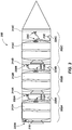
FIG. 3 is a cutaway side view of a rocket motor that includes an ordnance system including at least one firing unit according to an embodiment of the present disclosure; and -
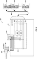
FIG. 4 is a schematic diagram of an ordnance system according to an embodiment of the present disclosure. - In the following description, reference is made to the accompanying drawings in which is shown, by way of illustration, specific embodiments of the present disclosure. Other embodiments may be utilized and changes may be made without departing from the scope of the appended claims. The following detailed description is not to be taken in a limiting sense, and the scope of the claimed invention is defined only by the appended claims. Furthermore, specific implementations shown and described are only examples and should not be construed as the only way to implement or partition the present disclosure into functional elements unless specified otherwise herein. It will be readily apparent to one of ordinary skill in the art that the various embodiments of the present disclosure may be practiced by numerous other partitioning solutions.
- In the following description, elements, circuits, and functions may be shown in block diagram form in order not to obscure the present disclosure in unnecessary detail. Additionally, block definitions and partitioning of logic between various blocks is exemplary of a specific implementation. It will be readily apparent to one of ordinary skill in the art that the present disclosure may be practiced by numerous other partitioning solutions. Those of ordinary skill in the art would understand that information and signals may be represented using any of a variety of different technologies and techniques. For example, data, instructions, commands, information, signals, bits, symbols, and chips that may be referenced throughout the above description may be represented by voltages, currents, electromagnetic waves, magnetic fields or particles, optical fields or particles, or any combination thereof. Some drawings may illustrate signals as a single signal for clarity of presentation and description. It will be understood by a person of ordinary skill in the art that the signal may represent a bus of signals, wherein the bus may have a variety of bit widths and the present disclosure may be implemented on any number of data signals including a single data signal.
- The various illustrative logical blocks, modules, and circuits described in connection with the embodiments disclosed herein may be implemented or performed with a general-purpose processor, a special-purpose processor, a Digital Signal Processor (DSP), an Application-Specific Integrated Circuit (ASIC), a Field-Programmable Gate Array (FPGA) or other programmable logic device, a controller, discrete gate or transistor logic, discrete hardware components, or any combination thereof designed to perform the functions described herein. A general-purpose processor may be a microprocessor, but in the alternative, the processor may be any conventional processor, controller, microcontroller, or state machine. A general-purpose processor may be considered a special-purpose processor while the general-purpose processor executes instructions (e.g., software code) stored on a computer-readable medium. A processor may also be implemented as a combination of computing devices, such as a combination of a DSP and a microprocessor, a plurality of microprocessors, one or more microprocessors in conjunction with a DSP core, or any other such configuration.
- Also, it is noted that the embodiments may be described in terms of a process that may be depicted as a flowchart, a flow diagram, a structure diagram, or a block diagram. Although a process may describe operational acts as a sequential process, many of these acts can be performed in another sequence, in parallel, or substantially concurrently. In addition, the order of the acts may be re-arranged. A process may correspond to a method, a function, a procedure, a subroutine, a subprogram, etc. Furthermore, the methods disclosed herein may be implemented in hardware, software, or both. If implemented in software, the functions may be stored or transmitted as one or more instructions or code on computer readable media. Computer-readable media includes both computer storage media and communication media, including any medium that facilitates transfer of a computer program from one place to another.
- It should be understood that any reference to an element herein using a designation such as "first," "second," and so forth does not limit the quantity or order of those elements, unless such limitation is explicitly stated. Rather, these designations may be used herein as a convenient method of distinguishing between two or more elements or instances of an element. Thus, a reference to first and second elements does not mean that only two elements may be employed or that the first element must precede the second element in some manner. In addition, unless stated otherwise, a set of elements may comprise one or more elements.
- Embodiments of the present disclosure include ordnance systems that may be integrated or utilized with various types of airframes including rockets, satellites, missiles, launch vehicles, or other such devices where ordnances are utilized to initiate various ordnance events. Such ordnances may include, for example, ignition devices, exploding bolts, actuators, gas generators, separation devices, pressure equalization and ventilation devices, and other similar devices, which are individually and collectively referred to hereinafter as "ordnances."
-
FIG. 1 is a multiple-stage rocket motor 100 having a conventionalavionics control system 110 andordnance control system 120. Theordnance control system 120 may be integrated with theavionics control system 110, such that theordnance control system 120 and theavionics control system 110 are located together (indicated byoval 101, which is enlarged asbox 101 to provide the additional detail shown). In addition, conventionally theordnance control system 120 and theavionics control system 110 are positioned at a location that is separate fromindividual stages stage rocket motor 100. For example, as shown inFIG. 1 , the electronics of theavionics control system 110 and theordnance control system 120 are located near thecone 104 of the multiple-stage rocket motor 100. - The
avionics control system 110 is configured to manage the flight controls for the multiple-stage rocket motor 100. Theavionics control system 110 may include various control units, sensors, monitoring systems, etc., such as aflight computer 112, aninertial measurement unit 114,telemetry encoder 116, andinstrumentation signal conditioner 118. Theordnance control system 120 may be configured to provide power and control for the various ordnance units (not shown) of thestages ordnance control system 120 may include power andordnance controller 122, power relay board 124, andordnance relay board 126. Power supplies, such asavionics battery 111 andordnance battery 121 may provide power for operation of the various components of theavionics control system 110 and theordnance control system 120. - As shown in
FIG. 1 , power signals 125 andcontrol signals 127 for the ordnance units are conventionally generated on individual wires. For example, eachindividual power signal 125 may be transmitted over a separate wire to an individual ordnance unit to provide power thereto. Likewise, eachindividual control signal 127 may be analog signals transmitted over a separate wire instructing individual components how to perform. Such a configuration may result in complicated cabling paths for the power distribution and control systems throughout thevarious stages stage rocket motor 100, which may result in implementation and spacing difficulties, noise issues, complexity in timing ordnance firing events as well as timing for other events, weight issues, among other potential issues recognized by the inventors. -
FIG. 2 is a multiple-stage rocket motor 200 having anavionics control system 210 andordnance control system 220 according to an embodiment of the present disclosure. Theordnance control system 220 may include at least some components that are separate from theavionics control system 210, such as being distributed throughout thevarious stages stage rocket motor 200. As indicated by oval 201 (which is enlarged asbox 201 to provide the additional detail shown), the electronics of theavionics control system 210 is located near thecone 204 of the multiple-stage rocket motor 200. As shown inFIG. 2 , some of the components associated with theordnance control system 220 may also be located near thecone 204 along with theavionics control system 210. - The
avionics control system 210 may be configured to manage at least some of the flight controls of the multiple-stage rocket motor 200. Theavionics control system 210 may include various control units, sensors, monitoring systems, etc., such as aflight computer 212, aninertial measurement unit 214, and atelemetry encoder 216. Theavionics control system 210 may also include other components not specifically shown inFIG. 2 , such as an instrumentation signal conditioner (FIG. 1 ). Theordnance control system 220 may be configured to provide power and control for the various ordnance units (not shown) of thestages ordnance control system 220 may include power controller andconditioner 222, and a plurality ofstage controllers stages stage rocket motor 200. Power components, such asavionics battery 211,ordnance battery 221, and ground umbilical 205 may be used to provide power for operation of the various components of theavionics control system 210 and theordnance control system 220. - The plurality of
stages first stage 202A, asecond stage 202B, and athird stage 202C. Similarly, other components associated with each stage may be referred to with a similar alphanumeric designation (i.e., 2##A, 2##B, 2##C). Eachstage own ordnance controller ordnance controllers respective stage ordnance controllers - The
stage controllers data communication signals 213 therebetween, and the power controller andconditioner 222 to receive power signals 223. Although shown as separate lines, the data communication signals 213 and the power signals 223 may be coupled to thestage controllers stage controllers conditioner 222 to receive itspower signal 223. In some embodiments, thestage controllers conditioner 222 that is tapped off of to receive itspower signal 223. According to the invention, thestage controllers conditioner 222 may pass through to enable an individual stage controller (e.g.,third stage controller 224C) to disable power to itself, as well as to the stage controllers downstream (e.g.,second stage controller 224B,first stage controller 224A). Such a configuration will be described more fully below with respect toFIGS. 3 and4 . - The
stage controllers respective power signals stage controllers flight computer 212 may send some commands to thestage controllers stage controllers flight computer 212. Thus, eachstage controller stage flight computer 212. In some embodiments, one or more of thestage controllers third stage 202C (which, inFIG. 2 , is the stage that is attached to the cone 204) may have its flight controls managed by theflight computer 212 because of the close proximity and being essentially part of the same stage. In such an embodiment, thethird stage controller 224C may have a more simple configuration than theother stage controllers stage controllers flight computer 212. - Having some of the functions of the
ordnance control system 220 and theavionics control system 210 distributed down to eachstage ordnance control system 220 and theavionics control system 210 may contribute to components (and therefore also the weight thereof) being distributed throughout the multiple-stage rocket motor 200 rather than being located at a single location near thecone 204. As a result, asstages stage rocket motor 200, the electronics that were associated therewith also drop off. Because such electronics also drop off with thestages stage rocket motor 200, the result of which may be an increased payload capability to reach orbit, or an increased range for a given volume of propellant in the motor. In addition, having a distributed common bus architecture may provide additional benefits in initial construction by havingstage controllers stage stages - Each of the
stage controllers appropriate stage controller stage controller stage controllers stage controller firing units FIG. 3 ), and the desired data or command to be conveyed. Thestage controllers -
FIG. 3 is a cutaway side view of arocket motor 300 that includes an ordnance system including at least one firing unit according to an embodiment of the present disclosure. In particular, therocket motor 300 is a multiple-stage rocket motor. In other words, therocket motor 300 includes a plurality ofstages motor respective stage stages first stage 302A, asecond stage 302B, and athird stage 302C. Similarly, other components associated with eachstage - Each
stage own ordnance controller more firing units firing units motors separation joints stages respective stage firing units energy device 316 is shown as being located on thefirst stage 302A; however, such an energy device 316 (or multiple energy devices) may be located on any of thestages - As an example, the
firing units U.S. Patent Application Serial No. 13/608,571 , filed on the same day as the present application, and entitled "High Voltage Firing Unit, Ordnance System, and Method of Operating Same." - Because the
ordnance controllers firing units stage ordnance controller stage controllers stage stage controllers FIG. 2 ), such that theordnance controller - The
stage controllers FIG. 2 ) that acts as a host to control thestage controllers stage controllers firing unit firing units stage controllers stage controllers firing units respective stage controller stage controllers safety plug stage controllers firing units other stage controllers first safety plug 318A may disconnect the power signals to thefirst stage controller 324A, such that thefirst stage controller 324A may not provide power to thefiring units 330A of thefirst stage 302A. Disconnecting thesecond safety plug 318B may disconnect the power signals to thesecond stage controller 324B, such that thesecond stage controller 318B may not provide power to the firingunits 330B of thesecond stage 302B. In addition, disconnecting thesecond safety plug 318B may further disconnect the power signals to thefirst stage controller 324A (and associatedfiring units 330A) because thefirst stage controller 324A is downstream from thesecond stage controller 324B. Thus, disconnecting thesecond safety plug 318B affects the power to thefirst stage 302A regardless of the status of thefirst safety plug 318A. Likewise, disconnecting thethird safety plug 318C may disconnect the power signals to thethird stage controller 324C, such that thethird stage controller 324C may not provide power to the firingunits 330C of thethird stage 302C, as well as thesecond stage controller 324B andthird stage controller 324C downstream. Stage controllers for additional stages, if present, may be have a similar affect for downstream stages. - As a result, the
stage controllers first stage 302A may be constructed with thefirst safety plug 318A disconnected. As a result, the components of thefirst stage 302A may be isolated from power sources. The components may be safely tested without power, after which thesecond stage 302B may be constructed with thesecond safety plug 318B disconnected. Because thesecond safety plug 318B being disconnected also disconnects power to the stages downstream (e.g.,first stage 302A), thefirst safety plug 318A may be connected without power being provided to thefirst stage controller 324A. Likewise, after construction and testing of thesecond stage 302B is complete, thethird stage 302C may be constructed and tested with thethird safety plug 318C disconnected. Because thethird safety plug 318C being disconnected also disconnects power to the stages downstream (e.g.,first stage 302A,second stage 302B), thefirst safety plug 318A and thesecond safety plug 318B may be connected without power being provided to thefirst stage controller 324A and thesecond stage controller 324A. Thus, the safety plug (e.g.,third safety plug 318C) of the top-most stage controller (e.g.,third stage controller 324A) provides a manual safety plug for the entire stack ofstage controllers - Such a stacked configuration may provide ease in constructing and testing the
stages finished rocket motor 300 after all stages are constructed. As a result, stages 302A, 302B, 302C may be processed individually without regard for the status of the safety plugs for the stages below. In addition, the lower stages (e.g., 302A) may not require access points for the safety plugs (e.g., 318A) because the safety plugs (e.g., 318A) may be connected at an intermediate point of construction rather than at final construction of all stages. In operation, as thestages -
FIG. 4 is a schematic diagram of anordnance system 400 according to an embodiment of the present disclosure. Theordnance system 400 may include anordnance controller 424, which may be configured as a stage controller as described above. In addition, theordnance system 400 may include one or more firing units 430 (e.g., HVFUs), which may be configured generally as described above. As shown inFIG. 4 , theordnance controller 424 may be coupled to a plurality of firingunits 430 throughcommon cabling 402. Thecommon cabling 402 may include wiring for electronic safe and arm (ESA) power signals 440 and alogic power signal 442. - The
ordnance controller 424 may be serially coupled (e.g., stacked) with one or more additional ordnance controllers (not shown inFIG. 4 ) that are similarly configured. For example, theordnance controller 424 may receive the ESA power signals 440 from another ordnance controller (incoming), pass the ESA power signals 440 through thesafety plug 418, and pass the ESA power signals 440 to another ordnance controller (outgoing). As discussed with respect toFIG. 4 , eachordnance controller 424 may be associated with a respective stage of a multiple-stage rocket for controlling the firingunits 430 associated therewith. Thesafety plug 418 are configured to manually disconnect the ESA power signals 440, which may disconnect power to theordnance controller 424 as well as the other ordnance controllers downstream. As a result, the firingunits 430 for the present stage and downstream stages may not be able to be armed or charged with thesafety plug 418 disconnected. - If the
ordnance controller 424 ofFIG. 4 is thefirst stage controller 324A (FIG. 3 ), the outgoing ESA power signals 440 may be disconnected, because there is no downstream stage. The incoming ESA power signals 440 may be received from thesecond stage controller 324B (FIG. 3 ). If theordnance controller 424 ofFIG. 4 is thethird stage controller 324C, the outgoing ESA power signals 440 may be connected to thesecond stage controller 324B. The incoming ESA power signals 440, however, may be received from the power controller and conditioner 222 (FIG. 2 ) rather than a previous stage. - The
ordnance controller 424 may be configured to control generation of the ESA power signals 440, such as in response to control signals during an arming sequence. For example, theordnance controller 424 may includecontrol logic 410, which may include ESA armingpower switches ordnance controller 424 may be configured to communicatedata signals 450 with the firingunits 430 over a digital bus to determine a status of the firingunits 430 when determining the proper time to generate the ESA power signals 440. In some embodiments, thelogic power signal 442 may be routed outside of thesafety plug 418, such that the control and monitoring units of the firingunits 430 may operate to monitor voltages and currents within the firingunits 430 even in the absence of the ESA power signals 440. - The ordnance systems described herein may enable an electronic communication system that may replace conventional mechanical safe and arms, flexible confined detonating cords, thru-bulkhead initiators, lanyard pull initiators, and the like. As a result, there may be a reduction in complexity and reduced number of components, which may further result in lower cost, higher reliability, enhanced safety, lower electrical power requirements, and simplified vehicle integration. While reference is given to a distributed ordnance system being used within a multiple-stage rocket, other embodiments are also contemplated. For example, a distributed ordnance system may be employed in a variety of applications, such as in mining, drilling, demolition, among other applications in which it may be beneficial for an ordnance system to have ordnance controllers distributed to different areas (i.e., stages) relevant to a particular application.
Claims (15)
- A distributed ordnance system, comprising:a plurality of ordnance controllers (122, 224, 324,424), anda plurality of firing units (330, 430), each firing unit configured to receive a plurality of electronic safe and arm (ESA) power signals from an associated ordnance controller for both arming and charging the firing unit prior to discharge, wherein each ordnance controller of the plurality of ordnance controller:is operably coupled with at least one firing unit of the plurality of firing units;is configured to provide the plurality of ESA power signals to the at least one firing unit coupled therewith;is configured to communicate with the at least one firing unit for initiation of an ordnance event;characterised in that the ordnance controller includes a safety plug (318, 418) configured to manually disconnect the plurality of ESA power signals for the associated ordnance controller.
- The distributed ordnance system of claim 1, wherein each ordnance controller is operably coupled with the at least one firing unit coupled therewith through a digital communication bus.
- The distributed ordnance system of claim 1 or claim 2, wherein at least one ordnance controller of the plurality of ordnance controllers is operably coupled to at least one additional firing unit of the plurality of firing units.
- The distributed ordnance system of claim 2, the plurality of ESA power signals and the digital communication bus are provided within common cabling.
- The distributed ordnance system of claim 2, wherein the plurality of ordnance controllers are operably coupled to each other with a common bus that includes the plurality of ESA power signals provided from a main controller to the plurality of ordnance controllers.
- The distributed ordnance system of claim 5, wherein the common bus includes the digital communication bus provided from the main controller to the plurality of ordnance controllers.
- The distributed ordnance system of claim 1, wherein the safety plug is configured to manually disconnect the plurality of ESA power signals from downstream ordnance controllers of the plurality of ordnance controllers.
- The distributed ordnance system of claim 1 or claim 2, wherein the plurality of firing units comprise a plurality of high voltage firing units.
- A multiple-stage ordnance system, comprising:a first stage (102A, 202A, 302A), comprising:a first ordnance controller (224A, 324A) configured to control operation of a first ordnance event within the first stage; andat least one first firing unit (330A, 430A) operably coupled with the first ordnance controller to initiate the first ordnance event;a first safety plug (318A) configured to receive at least one electronic safe and arm (ESA) power signal and selectively provide the ESA power signal to the at least one first firing unit according to a state of a manual disconnect for the first safety plug; anda second stage (102B, 202B, 302B), comprising:a second ordnance controller (224B, 324B) configured to control operation of a second ordnance event within the second stage;at least one second firing unit (330B, 430B) operably coupled with the second ordnance controller to initiate the second ordnance event; anda second safety plug (318B) configured to receive the at least one ESA power signal from the first stage, and selectively provide the ESA power signal to the at least one first firing unit according to a state of a manual disconnect for the second safety plug.
- The multiple-stage ordnance system of claim 9, wherein each of the at least one first firing unit and the at least one second firing unit is individually addressable by the respective one of the first ordnance controller and the second ordnance controller.
- The multiple-stage ordnance system of claim 9 or claim 10, wherein the first ordnance controller is further configured to manage flight controls for the first stage of a multiple-stage flight vehicle.
- The multiple-stage ordnance system of claim 9 or claim 10, further comprising:an avionics control system operably coupled with the first ordnance controller and the second ordnance controller over a common bus architecture; anda power controller and conditioner located proximate the avionics control system, the power controller and conditioner configured to generate the at least one ESA power signal to each of the first ordnance controller and the second ordnance controller.
- The multiple-stage ordnance system of claim 12, wherein the first safety plug is further configured to selectively provide the at least one ESA power signal to the second safety plug of the second ordnance controller according to the state of the manual disconnect for the first safety plug.
- A method for controlling initiation of an energetic material, the method comprising:sending a control signal over a common communication bus to a plurality of ordnance controllers operably coupled to a plurality of firing units configured to ignite the energetic material, the control signal including a message including an address corresponding to the firing unit to be armed and charged; andsending a power signal over a common power bus to the plurality of ordnance controllers through safety plugs that correspond to an associated ordnance controller for manually disconnecting the power signal, the plurality of ordnance controllers further configured for providing the power signal to the firing unit to be armed and charged.
- The method of claim 14, further comprising:sending a fire command signal to the firing unit after being armed and charged;releasing energy from an energy storage device of the firing unit to an initiator responsive to the fire command signal.
Applications Claiming Priority (2)
| Application Number | Priority Date | Filing Date | Title |
|---|---|---|---|
| US13/608,824 US9127918B2 (en) | 2012-09-10 | 2012-09-10 | Distributed ordnance system, multiple stage ordnance system, and related methods |
| PCT/US2013/058902 WO2014084948A2 (en) | 2012-09-10 | 2013-09-10 | Distributed ordnance system, multiple stage ordnance system, and related methods |
Publications (2)
| Publication Number | Publication Date |
|---|---|
| EP2893289A2 EP2893289A2 (en) | 2015-07-15 |
| EP2893289B1 true EP2893289B1 (en) | 2017-08-16 |
Family
ID=50231894
Family Applications (1)
| Application Number | Title | Priority Date | Filing Date |
|---|---|---|---|
| EP13840177.3A Active EP2893289B1 (en) | 2012-09-10 | 2013-09-10 | Distributed ordnance system, multiple stage ordnance system, and related methods |
Country Status (4)
| Country | Link |
|---|---|
| US (1) | US9127918B2 (en) |
| EP (1) | EP2893289B1 (en) |
| JP (1) | JP6368310B2 (en) |
| WO (1) | WO2014084948A2 (en) |
Families Citing this family (10)
| Publication number | Priority date | Publication date | Assignee | Title |
|---|---|---|---|---|
| GB2490528B (en) * | 2011-05-05 | 2013-04-17 | Ew Simulation Technology Ltd | A self-propelled flying apparatus adapted to emulate a hostile firing action |
| CN103899438B (en) * | 2014-04-16 | 2015-10-14 | 上海航天电子通讯设备研究所 | A kind of carrier rocket three selects two ignition mechanisms |
| TR201807025U5 (en) * | 2016-06-09 | 2018-06-21 | Aselsan Elektronik Sanayi Ve Ticaret Anonim Sirketi | MODULAR SEARCHER TITLE |
| US9810515B1 (en) | 2017-02-03 | 2017-11-07 | Pacific Scientific Energetic Materials Company (California) LLC | Multi-level networked ordnance system |
| CN107368020B (en) * | 2017-06-19 | 2019-09-06 | 北京航天发射技术研究所 | A Highly Reliable Pre-shoot Sequential Action Triggering Method |
| US11353304B2 (en) | 2020-08-18 | 2022-06-07 | Raytheon Company | Safe booster jettison for tactical missiles |
| RU2751731C1 (en) * | 2020-10-29 | 2021-07-16 | Акционерное общество "Военно-промышленная корпорация "Научно-производственное объединение машиностроения" | Method for controlling space-purpose rocket converted from multistage liquid ballistic rocket |
| RU2751729C1 (en) * | 2020-10-29 | 2021-07-16 | Акционерное общество "Военно-промышленная корпорация "Научно-производственное объединение машиностроения" | Space rocket control method |
| PE20250698A1 (en) * | 2022-06-22 | 2025-03-06 | Orica Int Pte Ltd | SYSTEMS AND METHODS/PROCESSES |
| US20250206471A1 (en) * | 2023-12-22 | 2025-06-26 | Beyond Gravity Sweden Ab | Multichannel actuation system |
Family Cites Families (23)
| Publication number | Priority date | Publication date | Assignee | Title |
|---|---|---|---|---|
| US3142959A (en) | 1959-09-11 | 1964-08-04 | Phillips Petroleum Co | Range control of self propelled missile |
| US4391195A (en) * | 1979-08-21 | 1983-07-05 | Shann Peter C | Detonation of explosive charges and equipment therefor |
| US4602565A (en) | 1983-09-26 | 1986-07-29 | Reynolds Industries Inc. | Exploding foil detonator |
| US4586437A (en) | 1984-04-18 | 1986-05-06 | Asahi Kasei Kogyo Kabushiki Kaisha | Electronic delay detonator |
| US4635552A (en) | 1985-08-15 | 1987-01-13 | The United States Of America As Represented By The Secretary Of The Air Force | Unique signal, safe and arm device |
| US5070789A (en) | 1990-06-27 | 1991-12-10 | Cxa Ltd./Cxa Ltee | Electric exploding bridge wire initiators |
| US5444598A (en) | 1993-09-29 | 1995-08-22 | Raymond Engineering Inc. | Capacitor exploding foil initiator device |
| US5825098A (en) | 1997-02-21 | 1998-10-20 | Breed Automotive Technologies, Inc. | Vehicle safety device controller |
| US5912428A (en) | 1997-06-19 | 1999-06-15 | The Ensign-Bickford Company | Electronic circuitry for timing and delay circuits |
| WO1999029517A1 (en) * | 1997-12-05 | 1999-06-17 | Seeber Engineering Gmbh | Device with a mark-holder hopper for stamping distinguishing marks on moving parts |
| US6634298B1 (en) | 1998-12-21 | 2003-10-21 | The United States Of America As Represented By The Secretary Of The Navy | Fireset for a low energy exploding foil initiator: SCR driven MOSFET switch |
| US6584907B2 (en) | 2000-03-17 | 2003-07-01 | Ensign-Bickford Aerospace & Defense Company | Ordnance firing system |
| US7752970B2 (en) * | 2000-09-06 | 2010-07-13 | Ps/Emc West, Llc | Networked electronic ordnance system |
| US6718881B2 (en) | 2001-09-07 | 2004-04-13 | Alliant Techsystems Inc. | Ordnance control and initiation system and related method |
| US6992877B2 (en) | 2002-03-13 | 2006-01-31 | Alliant Techsystems Inc. | Electronic switching system for a detonation device |
| AR046387A1 (en) * | 2003-07-15 | 2005-12-07 | Detnet South Africa Pty Ltd | DETONATOR SYSTEM AND DETONATOR PROGRAMMING. |
| US7412321B2 (en) * | 2003-08-14 | 2008-08-12 | De Sylva Robert F | System and method for selectively disabling a vehicle |
| US7261028B2 (en) * | 2003-12-22 | 2007-08-28 | Alliant Techsystems, Inc. | Ordnance system with common bus, method of operation and aerospace vehicle including same |
| US8104719B2 (en) | 2005-11-17 | 2012-01-31 | Raytheon Company | Digital interface unit (DIU) and method for controlling stages of a multi-stage missle |
| EP2029960B1 (en) | 2006-06-09 | 2011-04-20 | Detnet South Africa (Pty) Ltd | Detonator cross-talk reduction |
| NZ592333A (en) * | 2008-10-24 | 2014-10-31 | Battelle Memorial Institute | Electronic detonator system |
| US8213151B2 (en) | 2008-12-31 | 2012-07-03 | Pacific Scientific Energetic Materials Company (California), LLC | Methods and systems for defining addresses for pyrotechnic devices networked in an electronic ordnance system |
| US8573124B2 (en) * | 2010-05-11 | 2013-11-05 | Orbital Sciences Corporation | Electronic safe/arm system and methods of use thereof |
-
2012
- 2012-09-10 US US13/608,824 patent/US9127918B2/en active Active
-
2013
- 2013-09-10 JP JP2015531309A patent/JP6368310B2/en active Active
- 2013-09-10 WO PCT/US2013/058902 patent/WO2014084948A2/en not_active Ceased
- 2013-09-10 EP EP13840177.3A patent/EP2893289B1/en active Active
Non-Patent Citations (1)
| Title |
|---|
| None * |
Also Published As
| Publication number | Publication date |
|---|---|
| US9127918B2 (en) | 2015-09-08 |
| WO2014084948A3 (en) | 2014-08-28 |
| JP6368310B2 (en) | 2018-08-01 |
| JP2015534029A (en) | 2015-11-26 |
| US20140069289A1 (en) | 2014-03-13 |
| WO2014084948A2 (en) | 2014-06-05 |
| EP2893289A2 (en) | 2015-07-15 |
Similar Documents
| Publication | Publication Date | Title |
|---|---|---|
| US9127918B2 (en) | Distributed ordnance system, multiple stage ordnance system, and related methods | |
| EP2893290B1 (en) | High voltage firing unit, ordnance system, and method of operating same | |
| US4714020A (en) | Enabling device for a gas generator of a forced dispersion munitions dispenser | |
| US7934682B2 (en) | Aircraft safety system | |
| US7278658B2 (en) | Ordinance firing system for land vehicle | |
| US6718881B2 (en) | Ordnance control and initiation system and related method | |
| CN111392071B (en) | Initiating explosive device detonation control system and testing method thereof | |
| US9250051B1 (en) | Squib initiation sequencer | |
| US10518907B2 (en) | Spacecraft device initiation system | |
| EP1497608A2 (en) | Ordnance firing system | |
| US4911382A (en) | Safe electro ballistic escape sequencing system | |
| EP1424536A1 (en) | Ignition isolating interrupt circuit | |
| EP2867609B1 (en) | Intermediate voltage arming | |
| CN109795720B (en) | Detonation control design method of initiating explosive device for spacecraft cabin separation | |
| US20180069352A1 (en) | Electrical device with shunt, and receptacle | |
| US12235061B1 (en) | Smart store communication interface (SSCI) compatible squib design | |
| US4939438A (en) | Relay control assembly | |
| EP3947156A1 (en) | Multipoint payload release system | |
| US11548649B2 (en) | Aircraft escape system and ejection seat sequencer for ejection systems | |
| US3273337A (en) | Linear explosive type igniter train for rocket motor | |
| Interbartolo | Apollo spacecraft and saturn v launch vehicle pyrotechnics/explosive devices | |
| Webster | Space Shuttle Solid Rocket Booster pyrotechnic initiation system description and lessons learned | |
| KR20030017148A (en) | Rocket Onboard Safety Device for 2nd or 3rd Stage Ignition |
Legal Events
| Date | Code | Title | Description |
|---|---|---|---|
| PUAI | Public reference made under article 153(3) epc to a published international application that has entered the european phase |
Free format text: ORIGINAL CODE: 0009012 |
|
| 17P | Request for examination filed |
Effective date: 20150409 |
|
| AK | Designated contracting states |
Kind code of ref document: A2 Designated state(s): AL AT BE BG CH CY CZ DE DK EE ES FI FR GB GR HR HU IE IS IT LI LT LU LV MC MK MT NL NO PL PT RO RS SE SI SK SM TR |
|
| AX | Request for extension of the european patent |
Extension state: BA ME |
|
| DAX | Request for extension of the european patent (deleted) | ||
| RAP1 | Party data changed (applicant data changed or rights of an application transferred) |
Owner name: ORBITAL ATK, INC. |
|
| GRAP | Despatch of communication of intention to grant a patent |
Free format text: ORIGINAL CODE: EPIDOSNIGR1 |
|
| INTG | Intention to grant announced |
Effective date: 20170223 |
|
| GRAS | Grant fee paid |
Free format text: ORIGINAL CODE: EPIDOSNIGR3 |
|
| GRAA | (expected) grant |
Free format text: ORIGINAL CODE: 0009210 |
|
| AK | Designated contracting states |
Kind code of ref document: B1 Designated state(s): AL AT BE BG CH CY CZ DE DK EE ES FI FR GB GR HR HU IE IS IT LI LT LU LV MC MK MT NL NO PL PT RO RS SE SI SK SM TR |
|
| REG | Reference to a national code |
Ref country code: GB Ref legal event code: FG4D |
|
| REG | Reference to a national code |
Ref country code: CH Ref legal event code: EP |
|
| REG | Reference to a national code |
Ref country code: IE Ref legal event code: FG4D |
|
| REG | Reference to a national code |
Ref country code: AT Ref legal event code: REF Ref document number: 919485 Country of ref document: AT Kind code of ref document: T Effective date: 20170915 |
|
| REG | Reference to a national code |
Ref country code: DE Ref legal event code: R096 Ref document number: 602013025255 Country of ref document: DE |
|
| REG | Reference to a national code |
Ref country code: FR Ref legal event code: PLFP Year of fee payment: 5 |
|
| REG | Reference to a national code |
Ref country code: NL Ref legal event code: MP Effective date: 20170816 |
|
| REG | Reference to a national code |
Ref country code: LT Ref legal event code: MG4D |
|
| REG | Reference to a national code |
Ref country code: AT Ref legal event code: MK05 Ref document number: 919485 Country of ref document: AT Kind code of ref document: T Effective date: 20170816 |
|
| PG25 | Lapsed in a contracting state [announced via postgrant information from national office to epo] |
Ref country code: FI Free format text: LAPSE BECAUSE OF FAILURE TO SUBMIT A TRANSLATION OF THE DESCRIPTION OR TO PAY THE FEE WITHIN THE PRESCRIBED TIME-LIMIT Effective date: 20170816 Ref country code: LT Free format text: LAPSE BECAUSE OF FAILURE TO SUBMIT A TRANSLATION OF THE DESCRIPTION OR TO PAY THE FEE WITHIN THE PRESCRIBED TIME-LIMIT Effective date: 20170816 Ref country code: AT Free format text: LAPSE BECAUSE OF FAILURE TO SUBMIT A TRANSLATION OF THE DESCRIPTION OR TO PAY THE FEE WITHIN THE PRESCRIBED TIME-LIMIT Effective date: 20170816 Ref country code: NO Free format text: LAPSE BECAUSE OF FAILURE TO SUBMIT A TRANSLATION OF THE DESCRIPTION OR TO PAY THE FEE WITHIN THE PRESCRIBED TIME-LIMIT Effective date: 20171116 Ref country code: NL Free format text: LAPSE BECAUSE OF FAILURE TO SUBMIT A TRANSLATION OF THE DESCRIPTION OR TO PAY THE FEE WITHIN THE PRESCRIBED TIME-LIMIT Effective date: 20170816 Ref country code: SE Free format text: LAPSE BECAUSE OF FAILURE TO SUBMIT A TRANSLATION OF THE DESCRIPTION OR TO PAY THE FEE WITHIN THE PRESCRIBED TIME-LIMIT Effective date: 20170816 |
|
| PG25 | Lapsed in a contracting state [announced via postgrant information from national office to epo] |
Ref country code: ES Free format text: LAPSE BECAUSE OF FAILURE TO SUBMIT A TRANSLATION OF THE DESCRIPTION OR TO PAY THE FEE WITHIN THE PRESCRIBED TIME-LIMIT Effective date: 20170816 Ref country code: GR Free format text: LAPSE BECAUSE OF FAILURE TO SUBMIT A TRANSLATION OF THE DESCRIPTION OR TO PAY THE FEE WITHIN THE PRESCRIBED TIME-LIMIT Effective date: 20171117 Ref country code: IS Free format text: LAPSE BECAUSE OF FAILURE TO SUBMIT A TRANSLATION OF THE DESCRIPTION OR TO PAY THE FEE WITHIN THE PRESCRIBED TIME-LIMIT Effective date: 20171216 Ref country code: BG Free format text: LAPSE BECAUSE OF FAILURE TO SUBMIT A TRANSLATION OF THE DESCRIPTION OR TO PAY THE FEE WITHIN THE PRESCRIBED TIME-LIMIT Effective date: 20171116 Ref country code: LV Free format text: LAPSE BECAUSE OF FAILURE TO SUBMIT A TRANSLATION OF THE DESCRIPTION OR TO PAY THE FEE WITHIN THE PRESCRIBED TIME-LIMIT Effective date: 20170816 Ref country code: RS Free format text: LAPSE BECAUSE OF FAILURE TO SUBMIT A TRANSLATION OF THE DESCRIPTION OR TO PAY THE FEE WITHIN THE PRESCRIBED TIME-LIMIT Effective date: 20170816 Ref country code: PL Free format text: LAPSE BECAUSE OF FAILURE TO SUBMIT A TRANSLATION OF THE DESCRIPTION OR TO PAY THE FEE WITHIN THE PRESCRIBED TIME-LIMIT Effective date: 20170816 |
|
| PG25 | Lapsed in a contracting state [announced via postgrant information from national office to epo] |
Ref country code: RO Free format text: LAPSE BECAUSE OF FAILURE TO SUBMIT A TRANSLATION OF THE DESCRIPTION OR TO PAY THE FEE WITHIN THE PRESCRIBED TIME-LIMIT Effective date: 20170816 Ref country code: CZ Free format text: LAPSE BECAUSE OF FAILURE TO SUBMIT A TRANSLATION OF THE DESCRIPTION OR TO PAY THE FEE WITHIN THE PRESCRIBED TIME-LIMIT Effective date: 20170816 Ref country code: DK Free format text: LAPSE BECAUSE OF FAILURE TO SUBMIT A TRANSLATION OF THE DESCRIPTION OR TO PAY THE FEE WITHIN THE PRESCRIBED TIME-LIMIT Effective date: 20170816 |
|
| REG | Reference to a national code |
Ref country code: CH Ref legal event code: PL |
|
| REG | Reference to a national code |
Ref country code: DE Ref legal event code: R097 Ref document number: 602013025255 Country of ref document: DE |
|
| PG25 | Lapsed in a contracting state [announced via postgrant information from national office to epo] |
Ref country code: SM Free format text: LAPSE BECAUSE OF FAILURE TO SUBMIT A TRANSLATION OF THE DESCRIPTION OR TO PAY THE FEE WITHIN THE PRESCRIBED TIME-LIMIT Effective date: 20170816 Ref country code: EE Free format text: LAPSE BECAUSE OF FAILURE TO SUBMIT A TRANSLATION OF THE DESCRIPTION OR TO PAY THE FEE WITHIN THE PRESCRIBED TIME-LIMIT Effective date: 20170816 Ref country code: SK Free format text: LAPSE BECAUSE OF FAILURE TO SUBMIT A TRANSLATION OF THE DESCRIPTION OR TO PAY THE FEE WITHIN THE PRESCRIBED TIME-LIMIT Effective date: 20170816 Ref country code: MC Free format text: LAPSE BECAUSE OF FAILURE TO SUBMIT A TRANSLATION OF THE DESCRIPTION OR TO PAY THE FEE WITHIN THE PRESCRIBED TIME-LIMIT Effective date: 20170816 |
|
| PLBE | No opposition filed within time limit |
Free format text: ORIGINAL CODE: 0009261 |
|
| STAA | Information on the status of an ep patent application or granted ep patent |
Free format text: STATUS: NO OPPOSITION FILED WITHIN TIME LIMIT |
|
| REG | Reference to a national code |
Ref country code: IE Ref legal event code: MM4A |
|
| REG | Reference to a national code |
Ref country code: BE Ref legal event code: MM Effective date: 20170930 |
|
| PG25 | Lapsed in a contracting state [announced via postgrant information from national office to epo] |
Ref country code: LU Free format text: LAPSE BECAUSE OF NON-PAYMENT OF DUE FEES Effective date: 20170910 |
|
| 26N | No opposition filed |
Effective date: 20180517 |
|
| GBPC | Gb: european patent ceased through non-payment of renewal fee |
Effective date: 20171116 |
|
| PG25 | Lapsed in a contracting state [announced via postgrant information from national office to epo] |
Ref country code: IE Free format text: LAPSE BECAUSE OF NON-PAYMENT OF DUE FEES Effective date: 20170910 Ref country code: LI Free format text: LAPSE BECAUSE OF NON-PAYMENT OF DUE FEES Effective date: 20170930 Ref country code: CH Free format text: LAPSE BECAUSE OF NON-PAYMENT OF DUE FEES Effective date: 20170930 |
|
| PG25 | Lapsed in a contracting state [announced via postgrant information from national office to epo] |
Ref country code: BE Free format text: LAPSE BECAUSE OF NON-PAYMENT OF DUE FEES Effective date: 20170930 Ref country code: SI Free format text: LAPSE BECAUSE OF FAILURE TO SUBMIT A TRANSLATION OF THE DESCRIPTION OR TO PAY THE FEE WITHIN THE PRESCRIBED TIME-LIMIT Effective date: 20170816 |
|
| REG | Reference to a national code |
Ref country code: FR Ref legal event code: PLFP Year of fee payment: 6 |
|
| PG25 | Lapsed in a contracting state [announced via postgrant information from national office to epo] |
Ref country code: MT Free format text: LAPSE BECAUSE OF NON-PAYMENT OF DUE FEES Effective date: 20170910 |
|
| PG25 | Lapsed in a contracting state [announced via postgrant information from national office to epo] |
Ref country code: GB Free format text: LAPSE BECAUSE OF NON-PAYMENT OF DUE FEES Effective date: 20171116 |
|
| REG | Reference to a national code |
Ref country code: DE Ref legal event code: R082 Ref document number: 602013025255 Country of ref document: DE Representative=s name: BARDEHLE PAGENBERG PARTNERSCHAFT MBB PATENTANW, DE Ref country code: DE Ref legal event code: R081 Ref document number: 602013025255 Country of ref document: DE Owner name: NORTHROP GRUMMAN INNOVATION SYSTEMS, INC. (N.D, US Free format text: FORMER OWNER: ORBITAL ATK, INC., PLYMOUTH, MINN., US |
|
| PG25 | Lapsed in a contracting state [announced via postgrant information from national office to epo] |
Ref country code: HU Free format text: LAPSE BECAUSE OF FAILURE TO SUBMIT A TRANSLATION OF THE DESCRIPTION OR TO PAY THE FEE WITHIN THE PRESCRIBED TIME-LIMIT; INVALID AB INITIO Effective date: 20130910 |
|
| PG25 | Lapsed in a contracting state [announced via postgrant information from national office to epo] |
Ref country code: CY Free format text: LAPSE BECAUSE OF FAILURE TO SUBMIT A TRANSLATION OF THE DESCRIPTION OR TO PAY THE FEE WITHIN THE PRESCRIBED TIME-LIMIT Effective date: 20170816 |
|
| PG25 | Lapsed in a contracting state [announced via postgrant information from national office to epo] |
Ref country code: MK Free format text: LAPSE BECAUSE OF FAILURE TO SUBMIT A TRANSLATION OF THE DESCRIPTION OR TO PAY THE FEE WITHIN THE PRESCRIBED TIME-LIMIT Effective date: 20170816 |
|
| PG25 | Lapsed in a contracting state [announced via postgrant information from national office to epo] |
Ref country code: TR Free format text: LAPSE BECAUSE OF FAILURE TO SUBMIT A TRANSLATION OF THE DESCRIPTION OR TO PAY THE FEE WITHIN THE PRESCRIBED TIME-LIMIT Effective date: 20170816 |
|
| PG25 | Lapsed in a contracting state [announced via postgrant information from national office to epo] |
Ref country code: PT Free format text: LAPSE BECAUSE OF FAILURE TO SUBMIT A TRANSLATION OF THE DESCRIPTION OR TO PAY THE FEE WITHIN THE PRESCRIBED TIME-LIMIT Effective date: 20170816 |
|
| PG25 | Lapsed in a contracting state [announced via postgrant information from national office to epo] |
Ref country code: HR Free format text: LAPSE BECAUSE OF FAILURE TO SUBMIT A TRANSLATION OF THE DESCRIPTION OR TO PAY THE FEE WITHIN THE PRESCRIBED TIME-LIMIT Effective date: 20170816 |
|
| PG25 | Lapsed in a contracting state [announced via postgrant information from national office to epo] |
Ref country code: AL Free format text: LAPSE BECAUSE OF FAILURE TO SUBMIT A TRANSLATION OF THE DESCRIPTION OR TO PAY THE FEE WITHIN THE PRESCRIBED TIME-LIMIT Effective date: 20170816 |
|
| P01 | Opt-out of the competence of the unified patent court (upc) registered |
Effective date: 20230607 |
|
| PGFP | Annual fee paid to national office [announced via postgrant information from national office to epo] |
Ref country code: DE Payment date: 20250919 Year of fee payment: 13 |
|
| PGFP | Annual fee paid to national office [announced via postgrant information from national office to epo] |
Ref country code: IT Payment date: 20250923 Year of fee payment: 13 |
|
| PGFP | Annual fee paid to national office [announced via postgrant information from national office to epo] |
Ref country code: FR Payment date: 20250922 Year of fee payment: 13 |