EP2892606B1 - Cannula seal - Google Patents
Cannula seal Download PDFInfo
- Publication number
- EP2892606B1 EP2892606B1 EP13835879.1A EP13835879A EP2892606B1 EP 2892606 B1 EP2892606 B1 EP 2892606B1 EP 13835879 A EP13835879 A EP 13835879A EP 2892606 B1 EP2892606 B1 EP 2892606B1
- Authority
- EP
- European Patent Office
- Prior art keywords
- seal
- ribs
- hourglass
- cap portion
- cannula
- Prior art date
- Legal status (The legal status is an assumption and is not a legal conclusion. Google has not performed a legal analysis and makes no representation as to the accuracy of the status listed.)
- Active
Links
- 239000000463 material Substances 0.000 claims description 8
- 239000000314 lubricant Substances 0.000 claims description 3
- 150000001875 compounds Chemical class 0.000 description 8
- 238000007789 sealing Methods 0.000 description 7
- 229920001971 elastomer Polymers 0.000 description 6
- 238000003780 insertion Methods 0.000 description 5
- 230000037431 insertion Effects 0.000 description 5
- 241000405070 Percophidae Species 0.000 description 4
- 239000012530 fluid Substances 0.000 description 4
- 238000001356 surgical procedure Methods 0.000 description 3
- 229920002943 EPDM rubber Polymers 0.000 description 2
- 239000003292 glue Substances 0.000 description 2
- 229920003049 isoprene rubber Polymers 0.000 description 2
- 238000002324 minimally invasive surgery Methods 0.000 description 2
- 229920001195 polyisoprene Polymers 0.000 description 2
- 230000002787 reinforcement Effects 0.000 description 2
- JOYRKODLDBILNP-UHFFFAOYSA-N Ethyl urethane Chemical compound CCOC(N)=O JOYRKODLDBILNP-UHFFFAOYSA-N 0.000 description 1
- 210000001015 abdomen Anatomy 0.000 description 1
- 230000015572 biosynthetic process Effects 0.000 description 1
- 229920005556 chlorobutyl Polymers 0.000 description 1
- 230000000295 complement effect Effects 0.000 description 1
- 238000002574 cystoscopy Methods 0.000 description 1
- 238000001839 endoscopy Methods 0.000 description 1
- 238000003384 imaging method Methods 0.000 description 1
- 238000001746 injection moulding Methods 0.000 description 1
- 238000002357 laparoscopic surgery Methods 0.000 description 1
- 238000004519 manufacturing process Methods 0.000 description 1
- 230000013011 mating Effects 0.000 description 1
- 238000000034 method Methods 0.000 description 1
- 239000000203 mixture Substances 0.000 description 1
- 238000012986 modification Methods 0.000 description 1
- 230000004048 modification Effects 0.000 description 1
- 229920003225 polyurethane elastomer Polymers 0.000 description 1
- 230000001681 protective effect Effects 0.000 description 1
- 238000002432 robotic surgery Methods 0.000 description 1
- 229910052710 silicon Inorganic materials 0.000 description 1
- 239000010703 silicon Substances 0.000 description 1
- 229920002379 silicone rubber Polymers 0.000 description 1
- 239000004945 silicone rubber Substances 0.000 description 1
Images


Classifications
-
- A—HUMAN NECESSITIES
- A61—MEDICAL OR VETERINARY SCIENCE; HYGIENE
- A61M—DEVICES FOR INTRODUCING MEDIA INTO, OR ONTO, THE BODY; DEVICES FOR TRANSDUCING BODY MEDIA OR FOR TAKING MEDIA FROM THE BODY; DEVICES FOR PRODUCING OR ENDING SLEEP OR STUPOR
- A61M39/00—Tubes, tube connectors, tube couplings, valves, access sites or the like, specially adapted for medical use
- A61M39/22—Valves or arrangement of valves
- A61M39/26—Valves closing automatically on disconnecting the line and opening on reconnection thereof
-
- A—HUMAN NECESSITIES
- A61—MEDICAL OR VETERINARY SCIENCE; HYGIENE
- A61M—DEVICES FOR INTRODUCING MEDIA INTO, OR ONTO, THE BODY; DEVICES FOR TRANSDUCING BODY MEDIA OR FOR TAKING MEDIA FROM THE BODY; DEVICES FOR PRODUCING OR ENDING SLEEP OR STUPOR
- A61M39/00—Tubes, tube connectors, tube couplings, valves, access sites or the like, specially adapted for medical use
- A61M39/20—Closure caps or plugs for connectors or open ends of tubes
-
- A—HUMAN NECESSITIES
- A61—MEDICAL OR VETERINARY SCIENCE; HYGIENE
- A61M—DEVICES FOR INTRODUCING MEDIA INTO, OR ONTO, THE BODY; DEVICES FOR TRANSDUCING BODY MEDIA OR FOR TAKING MEDIA FROM THE BODY; DEVICES FOR PRODUCING OR ENDING SLEEP OR STUPOR
- A61M39/00—Tubes, tube connectors, tube couplings, valves, access sites or the like, specially adapted for medical use
- A61M39/02—Access sites
- A61M39/06—Haemostasis valves, i.e. gaskets sealing around a needle, catheter or the like, closing on removal thereof
- A61M2039/0633—Haemostasis valves, i.e. gaskets sealing around a needle, catheter or the like, closing on removal thereof the seal being a passive seal made of a resilient material with or without an opening
- A61M2039/064—Slit-valve
-
- A—HUMAN NECESSITIES
- A61—MEDICAL OR VETERINARY SCIENCE; HYGIENE
- A61M—DEVICES FOR INTRODUCING MEDIA INTO, OR ONTO, THE BODY; DEVICES FOR TRANSDUCING BODY MEDIA OR FOR TAKING MEDIA FROM THE BODY; DEVICES FOR PRODUCING OR ENDING SLEEP OR STUPOR
- A61M39/00—Tubes, tube connectors, tube couplings, valves, access sites or the like, specially adapted for medical use
- A61M39/02—Access sites
- A61M39/06—Haemostasis valves, i.e. gaskets sealing around a needle, catheter or the like, closing on removal thereof
- A61M2039/0633—Haemostasis valves, i.e. gaskets sealing around a needle, catheter or the like, closing on removal thereof the seal being a passive seal made of a resilient material with or without an opening
- A61M2039/0646—Duckbill-valve
-
- A—HUMAN NECESSITIES
- A61—MEDICAL OR VETERINARY SCIENCE; HYGIENE
- A61M—DEVICES FOR INTRODUCING MEDIA INTO, OR ONTO, THE BODY; DEVICES FOR TRANSDUCING BODY MEDIA OR FOR TAKING MEDIA FROM THE BODY; DEVICES FOR PRODUCING OR ENDING SLEEP OR STUPOR
- A61M39/00—Tubes, tube connectors, tube couplings, valves, access sites or the like, specially adapted for medical use
- A61M39/02—Access sites
- A61M39/06—Haemostasis valves, i.e. gaskets sealing around a needle, catheter or the like, closing on removal thereof
- A61M2039/0686—Haemostasis valves, i.e. gaskets sealing around a needle, catheter or the like, closing on removal thereof comprising more than one seal
-
- A—HUMAN NECESSITIES
- A61—MEDICAL OR VETERINARY SCIENCE; HYGIENE
- A61M—DEVICES FOR INTRODUCING MEDIA INTO, OR ONTO, THE BODY; DEVICES FOR TRANSDUCING BODY MEDIA OR FOR TAKING MEDIA FROM THE BODY; DEVICES FOR PRODUCING OR ENDING SLEEP OR STUPOR
- A61M39/00—Tubes, tube connectors, tube couplings, valves, access sites or the like, specially adapted for medical use
- A61M39/22—Valves or arrangement of valves
- A61M39/24—Check- or non-return valves
- A61M2039/2433—Valve comprising a resilient or deformable element, e.g. flap valve, deformable disc
Definitions
- Embodiments of the present invention are related to surgery and, in particular, to a cannula seal.
- Minimally invasive surgery allows a patient to be operated upon through one or more small incisions or a natural body orifice by using elongated surgical instruments introduced to an internal surgical site.
- an imaging device is also introduced to the surgical site in the same way so that a surgeon may see the instruments while working at the surgical site.
- the surgical site is often located inside a body cavity, such as the patient's abdomen.
- the body cavity may optionally be distended using a clear fluid such as an insufflation gas, typically CO 2 .
- the one or more surgical instruments are inserted through a cannula in order to reach the surgical site.
- Each cannula is inserted into an incision made in the patient, and one or more instruments are inserted through the cannula in order to reach the surgical site and to perform surgical operations.
- Cannula seals are used to provide a seal between the cannula and the inserted instrument, for example against insufflation gas leakage. Therefore, there is a need to develop improved cannula seals for surgery.
- EP 2 305 148 refers to a surgical access device including a valve housing and an instrument receiving element mounted in the valve housing having an aperture for flexibly receiving and directing instruments having a wide range of diameters.
- the instrument receiving element includes a braid or mesh tube generally shaped like an hourglass.
- the surgical access device may include an access septum seal molded from a gel material. The surgical access device can flexibly engage instruments having diameters ranging from about 3.5 mm to about 12.9 mm.
- EP 2 143 393 refers to a surgical protection device which has expandable insertion opening and trocar.
- a retaining element is provided in a portion of outer surface of protective elements for bringing into contact with the sealing element.
- WO 95/32019 refers to a trocar having a working channel extending along an axis between a distal end and a proximal end that includes a cannula at the distal end and a housing at the proximal end defining a working channel of the trocar.
- a valve disposed in the working channel separates the trocar into regions proximal of the valve and regions distal of the valve.
- the valve includes elastomeric means forming a first seal that is openly closable across the working channel.
- a wall of the valve extends radially outwardly of the elastomeric means and forms a second seal with the housing.
- the trocar also includes means for defining a passage extending from regions exterior of the trocar through the regions proximal of the valve and into the regions distal of the valve. Valve means disposed across this passage controls the administration of fluid through the passage and into the working channel of the cannula.
- US 2008/051739 refers to a seal assembly which establishes sealing engagement with a plurality of differently dimensioned instruments passing through a trocar.
- the seal assembly is a caged seal assembly movably disposed within the trocar and includes at least two seal segments disposable into and out of a sealing orientation relative to the instrument.
- a cage structure of the seal assembly includes at least two cage segments each connected to a seal segment, a biasing assembly connected to the cage structure and disposed and structured to normally bias the seal segments into sealing orientation.
- a cannula seal includes a cap portion, the cap portion fitting over a cannula; and a valve portion, the valve portion including an hourglass seal, a plurality of ribs formed around a perimeter of the hourglass seal, and a cross slit seal, the hourglass seal, the ribs and the cross slit seal being a single fabricated piece; wherein the hourglass seal includes a top sidewall and a bottom sidewall that meet at a junction; wherein each of the plurality of ribs extends along the top sidewall, across the junction, and along the bottom sidewall; and wherein the plurality of ribs includes four ribs evenly spaced around the junction, or the ribs of the plurality of ribs are aligned with slits of the cross slit seal.
- the cap portion includes a tab.
- the cap portion and the valve portion includes a tab.
- spatially relative terms such as “beneath”, “below”, “lower”, “above”, “upper”, “proximal”, “distal”, “horizontal”, “vertical” and the like-may be used to describe one element's or feature's relationship to another element or feature as illustrated in the figures.
- These spatially relative terms are intended to encompass different positions and orientations of the device in use or operation in addition to the position and orientation shown in the figures. For example, if the device in the figures is turned over, elements described as “below” or “beneath” other elements or features would then be “above” or “over” the other elements or features.
- the exemplary term “below” can encompass both positions and orientations of above and below.
- the device may be otherwise oriented (rotated 90 degrees or at other orientations), and the spatially relative descriptors used herein interpreted accordingly.
- descriptions of movement along and around various axes include various special device positions and orientations.
- the singular forms “a”, “an”, and “the” are intended to include the plural forms as well, unless the context indicates otherwise.
- the terms “comprises”, “comprising”, “includes”, and the like specify the presence of stated features, steps, operations, elements, and/or components but do not preclude the presence or addition of one or more other features, steps, operations, elements, components, and/or groups. Components described as coupled may be electrically or mechanically directly coupled, or they may be indirectly coupled via one or more intermediate components.
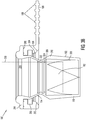
- FIG. 1 illustrates an exemplary cannula seal 100.
- cannula seal 100 includes a cap portion 104 and a valve portion 102, both of which may be formed, for example, of a polyisoprene rubber compound, silicone rubber, polyurethane elastomer, chlorobutyl rubber, ethylene propylene diene monomer (“EPDM”) rubber, or other compound.
- cap portion 104 and valve portion 102 are bonded together to form seal 100.
- seal 100 may be formed as a single continuous piece.
- Cap portion 104 allows seal 100 to mate with one end of a cannula (see e.g., Figure 4 ).
- Valve portion 102 provides the seal function, both with and without an inserted instrument.
- valve portion 102 includes a cross slit seal 110 and an hourglass seal 114.
- Cross slit seal 110 is illustrative of various duckbill type valves that may be used. Such valves seal on themselves in the absence of an inserted instrument.
- Duckbill type valves are formed from an elastomeric tube formed with inward folded walls to hold an end of the tube together so as to form various numbers of slits, such as one (single duckbill), two (double duckbill; cross slit), three (trifold; joker-type).
- the cross slit seal maintains its shape such that the two crossed slits are closed, thereby sealing against leakage across the seal.
- the seal resiliently deforms to allow the instrument to pass though.
- cross slit seal 110 is formed as two crossed slits 204 and 206 (shown in Figure 2 ).
- folded sidewalls 112 are concave. This concave shape helps to push the slits of seal 110 together in the presence of fluid pressure from outside the seal, such as from insufflation gas, because the force of the fluid near the slit is more directly across the slit.
- Hourglass seal 114 is arranged to seal around an instrument when the instrument is inserted through seal 100.
- Figure 1 illustrates an example with a single hourglass seal 114, multiple hourglass seals 114 can be included, stacked one atop another.
- hourglass seal 114 is sized to form a close fit with an instrument shaft when inserted through seal 100. This close fit may provide a slight clearance between hourglass seal 114 and the instrument shaft, or it may provide a slight friction fit. In some instances, hourglass seal 114 is sufficiently resilient that it will seal against instruments having different shaft diameters. For example, an hourglass seal 114 as depicted may provide sealing against both 12 mm and 13 mm instrument shaft diameters. Hourglass seal 114 provides an effective seal against an inserted instrument so that, for example, insufflation gas does not leak through seal 100 when an instrument is inserted.
- Cross slit seal 110 acts as a complement, providing an effective seal against, for example, insufflation gas leakage when the instrument is not inserted. Thus hourglass seal 114 and cross slit seal 110 work together to provide an effective seal against leakage through seal 100 whether or not an instrument is inserted.
- cap portion 104 includes a pull-off tab 106.
- Tab 106 assists the user in removing seal 100 from the top of a cannula.
- tab 106 can include ridges 108 that enhance the user's grip on tab 106.
- FIG. 2 illustrates some embodiments of seal 100.
- slits 204 and 206 of cross slit seal 110 are clearly shown. Further, an example of folded sidewalls 112 is illustrated.
- ribs 202 are formed around the outer perimeter of hourglass seal 114 in order to provide stiffening reinforcement for hourglass seal 114. Ribs 202 are formed integrally with hourglass seal 114, and hence with valve portion 102, so that the entire valve portion 102, including ribs 202, can be formed in, for example, a single injection molding process. In this way, the combined advantages of the hourglass and cross slit seals, plus the advantages offered by ribs 202, are formed as a single, inexpensively fabricated piece.
- the embodiment illustrated in Figure 2 has four ribs 202 (two are hidden from view) spaced apart approximately 90 degrees around the outer perimeter of hourglass seal 114. In other embodiments, other numbers of ribs 202 may be formed, such as three or six. In some embodiments, ribs 202 may be positioned around hourglass seal 114 to be aligned with the one or more slits in the duckbill valve.
- Ribs 202 provide several advantages for hourglass seal 114.
- ribs 202 add longitudinal (aligned from top to bottom) stiffness to hourglass seal 114 without substantially affecting the friction profile of hourglass seal 114.
- hourglass seal 114 is less likely to longitudinally deform as an instrument shaft moves through it-such longitudinal deformation causing a change in the friction profile between the instrument and seal.
- a relatively constant friction profile enhances smooth control, and may prevent or significantly reduce stick-slip, which is important during the constant insertion and withdrawal movements required in both manual and robotic surgery.
- the enhanced longitudinal stiffness that ribs 202 provide for hourglass seal 114 can help to prevent cross slit seal 110 from being damaged or pulled through seal 100 by an instrument being removed from seal 100.
- Figure 3A illustrates a cross section of an embodiment of seal 100.
- the cross section illustrated in Figure 3A does not pass through ribs 202.
- cross slit seal 110 includes sidewalls with a relatively thick portion 318 at the top that taper to a relatively thin portion 320 towards the bottom, close to slits 206 and 204.
- the relatively larger thickness (and consequent stiffness) of thick sidewall portion 318 helps to provide the ability of seal 110 to retain a round circumferential shape, and thus preserve cross slit seal 110's geometry for effective sealing.
- sidewall portion 320 helps to provide an enhanced closure of slits 206 and 204 when an instrument is not present and may provide an enhanced seal between the folded sidewall 112 and the instrument when an instrument is inserted through the slits.
- seal 114 is generally hourglass shaped (relatively larger diameter chambers joined by a relatively smaller diameter neck/waist region) and is formed from the sidewalls of two opposing generally cylindrical frustrums joined at their tops, shown as top sidewall 304 and bottom sidewall 306. Bottom sidewall 306 then joins with the thick top sidewall portion 318 of cross slit seal 110.
- Hourglass seal 114 is depicted as a lip seal that includes an O-ring type protrusion 302 (the lip portion of the seal) that is integrally formed at the junction of the two sidewalls 304 and 306 in valve portion 102, at the "neck" of the structure, where the inner diameter is smallest.
- Protrusion 302 extends inward from the sidewall junction to further reduce the inner diameter of the hourglass seal.
- more than one O-ring protrusion can be formed between sidewalls 304 and 306, the protrusions being positioned in a stacked series around the longitudinal axis.
- the O-ring type protrusion 302 may be omitted, so that either an annular flat or curved surface, or an annular vertex edge, is formed at the interior junction between sidewalls 304 and 306. Where applicable, features described in association with protrusion 302 are applicable in embodiments in which such a protrusion is not present.
- protrusion 302 is shown and described as an O-ring type, it should be understood that other protrusion shapes may be used to provide, for example, an annular flat or curved surface, or an annular vertex edge.
- seal 114 can include more than one protrusion.
- Figure 3B illustrates an embodiment where, in place of protrusion 302, multiple protrusions, protrusions 322 and 324, are provided.
- protrusions 322 and 324 may be formed with an inner diameter different from an inner diameter of one or more of the other protrusions, in order to accommodate a range of instrument shaft outer diameters.
- lubricant can be provided between stacked O-ring protrusions 322 and 324 in order to provide and control lubricant applied to an instrument.
- seal 114 can include any number of protrusions.
- Figure 3B further illustrates an instrument 330 being inserted through seal 100.
- Sidewalls 304 and 306 are shaped to support O-ring type protrusion 302 in such a way that some flexibility is allowed for lateral (aligned from side-to-side) motion of an instrument inserted into seal 100 and contacting O-ring protrusion 302. As shown in Figure 3A , each or both of sidewalls 304 and 306 can be tapered to be thinner where they join one another.
- This tapering may allow O-ring protrusion 302 to be relatively more resilient from side to side during manipulation of an instrument than if the sidewalls had a constant thickness, thus maintaining a seal against an instrument even if the instrument is manipulated in a fashion that distorts O-ring protrusion 302 or moves O-ring protrusion 302 away from the seal's centerline longitudinal axis.
- the sidewall tapering towards the neck of the hourglass seal allows O-ring protrusion 302 to move with the inserted instrument while maintaining an effective seal against the instrument shaft.
- sidewalls 304 and 306 can be longitudinally symmetrical in taper and extent. Such longitudinally symmetrical sidewalls 304 and 306 can provide a symmetrical friction profile for insertion and withdrawal of instruments inserted into seal 100, with resulting benefits as described above.
- O-ring protrusion 302's inner diameter is smaller than the outer diameter of the instrument that will be inserted into seal 100.
- a smaller diameter instrument can be accommodated by reducing the diameter of O-ring protrusion 302 accordingly.
- O-ring protrusion 302 themselves can be extended to reduce the diameter.
- the dimensions of side walls 304 and 306 can be adjusted to accommodate a smaller diameter O-ring protrusion 302.
- the overlap diameter can be chosen to maintain a seal under various conditions and to provide low friction for insertion of the instrument. The overlap can be chosen as a compromise with the contrary considerations of low friction and high seal effectiveness.
- cap portion 104 and valve portion 102 are joined at region 316 to form seal 100.
- One or more overflow traps 308 (one is shown in Figures 3A and 3B ; two in Figure 4 ) can be formed in either cap portion 104 or valve portion 102 as shown. Excess glue that is applied to the mating surfaces of cap portion 104 and valve portion 102 can be captured in overflow traps 308 before it overflows to an outside surface of valve portion 102 or cap portion 104. Any suitable glue, for example a medical grade cynoacrylate, can be used to bond cap portion 104 and valve portion 102 together. It should be understood that although the specific seal 100 embodiments are shown as being formed from separate cap 104 and valve 102 portions, for any design that can be accommodated by a relevant fabrication process, seal 100 may be formed as a single piece.
- an undercut region 310 is formed in cap portion 104 to receive a lip 404 of a cannula 402 (see Figure 4 ) and to hold seal 100 on cannula 402.
- top surface 314 of valve portion 102 can be rounded to help capture and guide an instrument into seal 100.
- surface 312 of cap portion 104 can be shaped (e.g., chamfered as shown) to facilitate the insertion of cap portion 104 over lip 404 of cannula 402 so that lip 404 is seated within undercut region 310.
- cap portion 104 is formed of a material (e.g., one rubber compound) that is relatively stiffer than the material used to form valve portion 102 (e.g., another rubber compound) in order to more effectively hold seal 100 on cannula 402.
- Valve portion 102 can be formed of a relatively softer rubber in order that cross slit seal 110 and hourglass seal 114 are more compliant and seal more effectively.
- the use of one compound for cap portion 104 and another compound for valve portion 102 allows a material to be chosen that best suits the function of each portion.
- the stiffness and other desirable material features of each of valve portion 102 and cap portion 104 can be adjusted in various embodiments by adjusting the composition of the compound used in formation.
- Valve portion 102 and cap portion 104 can be formed, for example of isoprene rubber.
- the isoprene rubber can be chlorinated, which reduces friction in cross slit seal 110 and in hourglass seal 114.
- valve portion 102 and cap portion 104 can be formed of polyisoprene rubber, silicon, or urethane.
- valve portion 102 and cap portion 104 can be made of a 30A to 60A durometer compound where valve portion 102 is a softer material than cap portion 104.
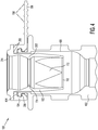
- Figure 4 shows a cross section of a seal 100 embodiment attached to an illustrative cannula 402.
- Cannula 402 is shaped to receive seal 100, and seal 100 is shaped to be removably attached to cannula 402.
- cannula 402 includes a lip 404 that is captured in undercut region 310.
- cannula 402 includes a bowl at its proximal end (farther away from the surgical site and outside the patient) that receives seal portion 102.
- the cross section of seal 100 is through ribs 202.
- ribs 202 can contact an inner surface of cannula 402, and this contact reinforces hourglass seal 114. The resulting reinforcement helps to increase the longitudinal stiffness as described above, and also to provide lateral stiffness for the hourglass seal 114.
- the outer surface of ribs 202 can be shaped to provide either a small clearance with, or a slight friction fit against, the cannula's inner wall.
Description
- This application claims priority to
U.S. Provisional Application No. 61/698,448, filed on September 7, 2012 - Embodiments of the present invention are related to surgery and, in particular, to a cannula seal.
- Minimally invasive surgery (e.g., endoscopy, laparoscopy, thoracoscopy, cystoscopy, and the like) allows a patient to be operated upon through one or more small incisions or a natural body orifice by using elongated surgical instruments introduced to an internal surgical site. In many instances, an imaging device is also introduced to the surgical site in the same way so that a surgeon may see the instruments while working at the surgical site. The surgical site is often located inside a body cavity, such as the patient's abdomen. The body cavity may optionally be distended using a clear fluid such as an insufflation gas, typically CO2. In traditional minimally invasive surgery, the one or more surgical instruments are inserted through a cannula in order to reach the surgical site. Each cannula is inserted into an incision made in the patient, and one or more instruments are inserted through the cannula in order to reach the surgical site and to perform surgical operations.
- Cannula seals are used to provide a seal between the cannula and the inserted instrument, for example against insufflation gas leakage. Therefore, there is a need to develop improved cannula seals for surgery.
-
EP 2 305 148 refers to a surgical access device including a valve housing and an instrument receiving element mounted in the valve housing having an aperture for flexibly receiving and directing instruments having a wide range of diameters. The instrument receiving element includes a braid or mesh tube generally shaped like an hourglass. The surgical access device may include an access septum seal molded from a gel material. The surgical access device can flexibly engage instruments having diameters ranging from about 3.5 mm to about 12.9 mm. -
EP 2 143 393 refers to a surgical protection device which has expandable insertion opening and trocar. A retaining element is provided in a portion of outer surface of protective elements for bringing into contact with the sealing element. -
WO 95/32019 -
US 2008/051739 refers to a seal assembly which establishes sealing engagement with a plurality of differently dimensioned instruments passing through a trocar. The seal assembly is a caged seal assembly movably disposed within the trocar and includes at least two seal segments disposable into and out of a sealing orientation relative to the instrument. A cage structure of the seal assembly includes at least two cage segments each connected to a seal segment, a biasing assembly connected to the cage structure and disposed and structured to normally bias the seal segments into sealing orientation. - The present invention provides a cannula seal as set out in the appended claims. In accordance with an aspect of the present invention, a cannula seal includes a cap portion, the cap portion fitting over a cannula; and a valve portion, the valve portion including an hourglass seal, a plurality of ribs formed around a perimeter of the hourglass seal, and a cross slit seal, the hourglass seal, the ribs and the cross slit seal being a single fabricated piece; wherein the hourglass seal includes a top sidewall and a bottom sidewall that meet at a junction; wherein each of the plurality of ribs extends along the top sidewall, across the junction, and along the bottom sidewall; and wherein the plurality of ribs includes four ribs evenly spaced around the junction, or the ribs of the plurality of ribs are aligned with slits of the cross slit seal. In some embodiments, the cap portion includes a tab. In some embodiments, the cap portion and the valve portion are integrally formed. In some embodiments, the cap portion and the valve portion are joined at a bonding region, which may include overflow traps.
- These and other embodiments are further discussed below with respect to the following figures.
-
-
Figure 1 illustrates an exemplary cannula seal. -
Figure 2 illustrates a cannula seal according to some embodiments of the present invention. -
Figure 3A illustrates a cross section of the cannula seal shown inFigure 1 . -
Figure 3B illustrates a cross section of another version of the cannula seal as shown inFigure 1 . -
Figure 4 illustrates an embodiment of a cannula seal according to the present invention inserted into a cannula. - In the following description, specific details are set forth describing some embodiments of the present invention. It will be apparent, however, to one skilled in the art that some embodiments may be practiced without some or all of these specific details. The specific embodiments disclosed herein are meant to be illustrative but not limiting. One skilled in the art may realize other elements that, although not specifically described here, are within the scope of this disclosure. In addition, to avoid unnecessary repetition, one or more features shown and described in association with one embodiment may be incorporated into other embodiments unless specifically described otherwise or if the one or more features would make an embodiment non-functional.
- Further, this description's terminology is not intended to limit the scope of the invention. For example, spatially relative terms-such as "beneath", "below", "lower", "above", "upper", "proximal", "distal", "horizontal", "vertical" and the like-may be used to describe one element's or feature's relationship to another element or feature as illustrated in the figures. These spatially relative terms are intended to encompass different positions and orientations of the device in use or operation in addition to the position and orientation shown in the figures. For example, if the device in the figures is turned over, elements described as "below" or "beneath" other elements or features would then be "above" or "over" the other elements or features. Thus, the exemplary term "below" can encompass both positions and orientations of above and below. The device may be otherwise oriented (rotated 90 degrees or at other orientations), and the spatially relative descriptors used herein interpreted accordingly. Likewise, descriptions of movement along and around various axes include various special device positions and orientations. In addition, the singular forms "a", "an", and "the" are intended to include the plural forms as well, unless the context indicates otherwise. And, the terms "comprises", "comprising", "includes", and the like specify the presence of stated features, steps, operations, elements, and/or components but do not preclude the presence or addition of one or more other features, steps, operations, elements, components, and/or groups. Components described as coupled may be electrically or mechanically directly coupled, or they may be indirectly coupled via one or more intermediate components.
-
Figure 1 illustrates anexemplary cannula seal 100. As illustrated inFigure 1 ,cannula seal 100 includes acap portion 104 and avalve portion 102, both of which may be formed, for example, of a polyisoprene rubber compound, silicone rubber, polyurethane elastomer, chlorobutyl rubber, ethylene propylene diene monomer ("EPDM") rubber, or other compound. As described in detail below, in someembodiments cap portion 104 andvalve portion 102 are bonded together to formseal 100. Alternatively,seal 100 may be formed as a single continuous piece.Cap portion 104 allowsseal 100 to mate with one end of a cannula (see e.g.,Figure 4 ).Valve portion 102 provides the seal function, both with and without an inserted instrument. As illustrated inFigure 1 ,valve portion 102 includes across slit seal 110 and anhourglass seal 114. -
Cross slit seal 110 is illustrative of various duckbill type valves that may be used. Such valves seal on themselves in the absence of an inserted instrument. Duckbill type valves are formed from an elastomeric tube formed with inward folded walls to hold an end of the tube together so as to form various numbers of slits, such as one (single duckbill), two (double duckbill; cross slit), three (trifold; joker-type). In the absence of an inserted object, the cross slit seal maintains its shape such that the two crossed slits are closed, thereby sealing against leakage across the seal. When an instrument is inserted through the seal, the seal resiliently deforms to allow the instrument to pass though. The resilient nature of the seal material keeps the slits close to the inserted instrument, and when the instrument is withdrawn, the seal returns to its closed position. As shown inFigure 1 , cross slitseal 110 is formed as two crossedslits 204 and 206 (shown inFigure 2 ). In some embodiments, folded sidewalls 112 are concave. This concave shape helps to push the slits ofseal 110 together in the presence of fluid pressure from outside the seal, such as from insufflation gas, because the force of the fluid near the slit is more directly across the slit. -
Hourglass seal 114 is arranged to seal around an instrument when the instrument is inserted throughseal 100. AlthoughFigure 1 illustrates an example with asingle hourglass seal 114, multiple hourglass seals 114 can be included, stacked one atop another. - The interior diameter of
hourglass seal 114 is sized to form a close fit with an instrument shaft when inserted throughseal 100. This close fit may provide a slight clearance betweenhourglass seal 114 and the instrument shaft, or it may provide a slight friction fit. In some instances,hourglass seal 114 is sufficiently resilient that it will seal against instruments having different shaft diameters. For example, anhourglass seal 114 as depicted may provide sealing against both 12 mm and 13 mm instrument shaft diameters.Hourglass seal 114 provides an effective seal against an inserted instrument so that, for example, insufflation gas does not leak throughseal 100 when an instrument is inserted. Cross slitseal 110 acts as a complement, providing an effective seal against, for example, insufflation gas leakage when the instrument is not inserted. Thushourglass seal 114 andcross slit seal 110 work together to provide an effective seal against leakage throughseal 100 whether or not an instrument is inserted. - As is further illustrated in
Figure 1 ,cap portion 104 includes a pull-offtab 106.Tab 106 assists the user in removingseal 100 from the top of a cannula. In some embodiments,tab 106 can includeridges 108 that enhance the user's grip ontab 106. -
Figure 2 illustrates some embodiments ofseal 100. As shown inFigure 2 , slits 204 and 206 ofcross slit seal 110 are clearly shown. Further, an example of foldedsidewalls 112 is illustrated. As is also shown inFigure 2 ,ribs 202 are formed around the outer perimeter ofhourglass seal 114 in order to provide stiffening reinforcement forhourglass seal 114.Ribs 202 are formed integrally withhourglass seal 114, and hence withvalve portion 102, so that theentire valve portion 102, includingribs 202, can be formed in, for example, a single injection molding process. In this way, the combined advantages of the hourglass and cross slit seals, plus the advantages offered byribs 202, are formed as a single, inexpensively fabricated piece. The embodiment illustrated inFigure 2 has four ribs 202 (two are hidden from view) spaced apart approximately 90 degrees around the outer perimeter ofhourglass seal 114. In other embodiments, other numbers ofribs 202 may be formed, such as three or six. In some embodiments,ribs 202 may be positioned aroundhourglass seal 114 to be aligned with the one or more slits in the duckbill valve. -
Ribs 202 provide several advantages forhourglass seal 114. First,ribs 202 add longitudinal (aligned from top to bottom) stiffness tohourglass seal 114 without substantially affecting the friction profile ofhourglass seal 114. Thus,hourglass seal 114 is less likely to longitudinally deform as an instrument shaft moves through it-such longitudinal deformation causing a change in the friction profile between the instrument and seal. A relatively constant friction profile enhances smooth control, and may prevent or significantly reduce stick-slip, which is important during the constant insertion and withdrawal movements required in both manual and robotic surgery. Further, the enhanced longitudinal stiffness thatribs 202 provide forhourglass seal 114 can help to preventcross slit seal 110 from being damaged or pulled throughseal 100 by an instrument being removed fromseal 100. Even if cross slitseal 110's sidewall starts to become inverted during instrument withdrawal, either from friction or from an instrument protrusion catching on an edge of a slit, the added longitudinal stability inhourglass seal 114 helps to prevent the cross slit seal from becoming fully inverted through the top ofseal 100, which then must be corrected in order to insert another instrument, and to prevent resulting damage to the cross slitseal 110, which would then have to be replaced during surgery. Thus, stiffeningribs 202 enhance the advantages of using bothhourglass seal 114 andcross slit seal 110 in asingle seal 100, while improving the number of cycles of use (the number of times an instrument can be inserted and removed from seal 100) forseal 100. -
Figure 3A illustrates a cross section of an embodiment ofseal 100. The cross section illustrated inFigure 3A does not pass throughribs 202. As shown inFigure 3A ,cross slit seal 110 includes sidewalls with a relativelythick portion 318 at the top that taper to a relativelythin portion 320 towards the bottom, close toslits thick sidewall portion 318 helps to provide the ability ofseal 110 to retain a round circumferential shape, and thus preservecross slit seal 110's geometry for effective sealing. Further, the relatively smaller thickness (and consequent flexibility and tendency to seal) ofsidewall portion 320 helps to provide an enhanced closure ofslits sidewall 112 and the instrument when an instrument is inserted through the slits. - As shown in
Figure 3A ,seal 114 is generally hourglass shaped (relatively larger diameter chambers joined by a relatively smaller diameter neck/waist region) and is formed from the sidewalls of two opposing generally cylindrical frustrums joined at their tops, shown astop sidewall 304 andbottom sidewall 306.Bottom sidewall 306 then joins with the thicktop sidewall portion 318 ofcross slit seal 110.Hourglass seal 114 is depicted as a lip seal that includes an O-ring type protrusion 302 (the lip portion of the seal) that is integrally formed at the junction of the twosidewalls valve portion 102, at the "neck" of the structure, where the inner diameter is smallest.Protrusion 302 extends inward from the sidewall junction to further reduce the inner diameter of the hourglass seal. In some embodiments, more than one O-ring protrusion can be formed betweensidewalls - In some embodiments, the O-
ring type protrusion 302 may be omitted, so that either an annular flat or curved surface, or an annular vertex edge, is formed at the interior junction betweensidewalls protrusion 302 are applicable in embodiments in which such a protrusion is not present. - In addition, although
protrusion 302 is shown and described as an O-ring type, it should be understood that other protrusion shapes may be used to provide, for example, an annular flat or curved surface, or an annular vertex edge. - In some embodiments, seal 114 can include more than one protrusion. For example,
Figure 3B illustrates an embodiment where, in place ofprotrusion 302, multiple protrusions,protrusions Figure 3B ,protrusions ring protrusions Figure 3B further illustrates aninstrument 330 being inserted throughseal 100. -
Sidewalls ring type protrusion 302 in such a way that some flexibility is allowed for lateral (aligned from side-to-side) motion of an instrument inserted intoseal 100 and contacting O-ring protrusion 302. As shown inFigure 3A , each or both ofsidewalls ring protrusion 302 to be relatively more resilient from side to side during manipulation of an instrument than if the sidewalls had a constant thickness, thus maintaining a seal against an instrument even if the instrument is manipulated in a fashion that distorts O-ring protrusion 302 or moves O-ring protrusion 302 away from the seal's centerline longitudinal axis. In other words, the sidewall tapering towards the neck of the hourglass seal allows O-ring protrusion 302 to move with the inserted instrument while maintaining an effective seal against the instrument shaft. Further, in some embodiments sidewalls 304 and 306 can be longitudinally symmetrical in taper and extent. Such longitudinallysymmetrical sidewalls seal 100, with resulting benefits as described above. - In some embodiments, O-
ring protrusion 302's inner diameter is smaller than the outer diameter of the instrument that will be inserted intoseal 100. A smaller diameter instrument can be accommodated by reducing the diameter of O-ring protrusion 302 accordingly. O-ring protrusion 302 themselves can be extended to reduce the diameter. In some embodiments, the dimensions ofside walls ring protrusion 302. The overlap diameter can be chosen to maintain a seal under various conditions and to provide low friction for insertion of the instrument. The overlap can be chosen as a compromise with the contrary considerations of low friction and high seal effectiveness. - Additionally, as shown in
Figures 3A and3B ,cap portion 104 andvalve portion 102 are joined atregion 316 to formseal 100. One or more overflow traps 308 (one is shown inFigures 3A and3B ; two inFigure 4 ) can be formed in eithercap portion 104 orvalve portion 102 as shown. Excess glue that is applied to the mating surfaces ofcap portion 104 andvalve portion 102 can be captured in overflow traps 308 before it overflows to an outside surface ofvalve portion 102 orcap portion 104. Any suitable glue, for example a medical grade cynoacrylate, can be used tobond cap portion 104 andvalve portion 102 together. It should be understood that although thespecific seal 100 embodiments are shown as being formed fromseparate cap 104 andvalve 102 portions, for any design that can be accommodated by a relevant fabrication process, seal 100 may be formed as a single piece. - As shown in
Figures 3A and3B , an undercutregion 310 is formed incap portion 104 to receive alip 404 of a cannula 402 (seeFigure 4 ) and to holdseal 100 oncannula 402. As an additional feature,top surface 314 ofvalve portion 102 can be rounded to help capture and guide an instrument intoseal 100. Additionally,surface 312 ofcap portion 104 can be shaped (e.g., chamfered as shown) to facilitate the insertion ofcap portion 104 overlip 404 ofcannula 402 so thatlip 404 is seated within undercutregion 310. - In some embodiments,
cap portion 104 is formed of a material (e.g., one rubber compound) that is relatively stiffer than the material used to form valve portion 102 (e.g., another rubber compound) in order to more effectively holdseal 100 oncannula 402.Valve portion 102 can be formed of a relatively softer rubber in order that cross slitseal 110 andhourglass seal 114 are more compliant and seal more effectively. The use of one compound forcap portion 104 and another compound forvalve portion 102 allows a material to be chosen that best suits the function of each portion. The stiffness and other desirable material features of each ofvalve portion 102 andcap portion 104 can be adjusted in various embodiments by adjusting the composition of the compound used in formation. -
Valve portion 102 andcap portion 104 can be formed, for example of isoprene rubber. In some embodiments, the isoprene rubber can be chlorinated, which reduces friction incross slit seal 110 and inhourglass seal 114. In some embodiments,valve portion 102 andcap portion 104 can be formed of polyisoprene rubber, silicon, or urethane. In some embodiments,valve portion 102 andcap portion 104 can be made of a 30A to 60A durometer compound wherevalve portion 102 is a softer material thancap portion 104.Figure 4 shows a cross section of aseal 100 embodiment attached to anillustrative cannula 402.Cannula 402 is shaped to receiveseal 100, and seal 100 is shaped to be removably attached tocannula 402. As such,cannula 402 includes alip 404 that is captured in undercutregion 310. Further,cannula 402 includes a bowl at its proximal end (farther away from the surgical site and outside the patient) that receivesseal portion 102. In theFigure 4 illustration, the cross section ofseal 100 is throughribs 202. As shown inFigure 4 ,ribs 202 can contact an inner surface ofcannula 402, and this contact reinforceshourglass seal 114. The resulting reinforcement helps to increase the longitudinal stiffness as described above, and also to provide lateral stiffness for thehourglass seal 114. The outer surface ofribs 202 can be shaped to provide either a small clearance with, or a slight friction fit against, the cannula's inner wall. - The above detailed description is provided to illustrate specific embodiments of the present invention and is not intended to be limiting. Numerous variations and modifications within the scope of the present invention are possible. The present invention is set forth in the following claims.
Claims (13)
- A cannula seal (100), comprising:a cap portion (104), the cap portion (104) fitting over a cannula; anda valve portion (102), the valve portion (102) includingan hourglass seal (114),a plurality of ribs (202) around a perimeter of the hourglass seal, anda cross slit seal (110);characterized in thatthe hourglass seal (114), the plurality of ribs (202) and the cross slit seal (110) are a single fabricated piece;wherein the hourglass seal (114) includes a top sidewall (304) and a bottom sidewall (306) that meet at a junction;wherein each of the plurality of ribs (202) extends along the top sidewall (304), across the junction, and along the bottom sidewall (206); andwherein the plurality of ribs includes four ribs (202) evenly spaced around the junction, or the ribs (202) of the plurality of ribs are aligned with slits of the cross slit seal (110).
- The seal (100) of claim 1, wherein the cap portion (104) includes a tab extending outward from an outer perimeter of the cap portion (104).
- The seal (100) of claim 1, wherein the cap portion (104) includes an undercut region that engages a lip on the cannula.
- The seal (100) of claim 1, wherein the cap portion (104) and the valve portion (102) are joined at a bonding region.
- The seal (100) of claim 4, wherein the bonding region includes one or more overflow traps.
- The seal (100) of claim 1, wherein the cap portion (104) is integrally formed with the valve portion (102).
- The seal (100) of claim 1, wherein the hourglass seal (114) includes an annular protrusion (322) at an inner of the junction of the sidewalls (304,306).
- The seal (100) of claim 7, wherein a thickness of at least one of the sidewalls (304,306) is tapered towards the junction.
- The seal (100) of claim 7, wherein a second annular protrusion (324) is provided adjacent the annular protrusion.
- The seal (100) of claim 9, including lubricant between the annular protrusion and the second annular protrusion, and preferably wherein the inner diameter is smaller than an outer shaft diameter.
- The seal (100) of claim 7, wherein the annular protrusion has an inner diameter sized to engage a shaft of an instrument.
- The seal (100) of claim 7, wherein the cross slit seal (110) includes a side wall, a thickness of the side wall of the cross slit seal (110) tapering towards a distal end of the cross slit seal (110), or
wherein the tapered side wall includes a folded wall (112) adjacent a slit (204,206), the folded wall (112) including a concave face. - The seal (100) of claim 1, wherein the cap portion (104) is formed of a stiffer material than is the valve portion (102).
Applications Claiming Priority (2)
| Application Number | Priority Date | Filing Date | Title |
|---|---|---|---|
| US201261698448P | 2012-09-07 | 2012-09-07 | |
| PCT/US2013/058617 WO2014039902A1 (en) | 2012-09-07 | 2013-09-06 | Cannula seal |
Publications (3)
| Publication Number | Publication Date |
|---|---|
| EP2892606A1 EP2892606A1 (en) | 2015-07-15 |
| EP2892606A4 EP2892606A4 (en) | 2016-03-02 |
| EP2892606B1 true EP2892606B1 (en) | 2019-08-28 |
Family
ID=50234040
Family Applications (1)
| Application Number | Title | Priority Date | Filing Date |
|---|---|---|---|
| EP13835879.1A Active EP2892606B1 (en) | 2012-09-07 | 2013-09-06 | Cannula seal |
Country Status (3)
| Country | Link |
|---|---|
| US (1) | US9913972B2 (en) |
| EP (1) | EP2892606B1 (en) |
| WO (1) | WO2014039902A1 (en) |
Families Citing this family (9)
| Publication number | Priority date | Publication date | Assignee | Title |
|---|---|---|---|---|
| EP3753510A1 (en) | 2014-03-17 | 2020-12-23 | Intuitive Surgical Operations, Inc. | Cannula seal assembly |
| US11400248B2 (en) * | 2015-06-23 | 2022-08-02 | Simplicity Airway, Inc. | Positive pressure ventilation elbow and related masks, systems, and methods |
| JP7019565B2 (en) * | 2015-06-23 | 2022-02-15 | シンプリシティ、エアウェイ、インコーポレイテッド | Positive pressure masks and related adapters, instruments and methods |
| CN105105842A (en) * | 2015-08-31 | 2015-12-02 | 杭州康基医疗器械有限公司 | Puncture outfit sealing cap with edges |
| US10151396B2 (en) * | 2015-11-29 | 2018-12-11 | Trong D Nguyen | Multi-purpose valve for vacuuming, de-vacuuming, gas injecting and pressure regulating |
| CN106806009B (en) * | 2015-12-02 | 2020-05-22 | 广州迪克医疗器械有限公司 | Anti-slip sealing ring for puncture outfit, sheath tube of puncture outfit and puncture outfit |
| WO2019222003A1 (en) * | 2018-05-15 | 2019-11-21 | Intuitive Surgical Operations, Inc. | Seal with curved rim |
| GB2594602B (en) * | 2018-12-13 | 2022-10-19 | Baska Kanag | A device for maintaining an airway in a patient |
| CN114129231A (en) * | 2020-09-03 | 2022-03-04 | 广州迪克医疗器械有限公司 | Pressure-resistant sealing ring for puncture outfit, puncture outfit sheath tube and puncture outfit |
Family Cites Families (23)
| Publication number | Priority date | Publication date | Assignee | Title |
|---|---|---|---|---|
| US4960412A (en) * | 1988-04-15 | 1990-10-02 | Universal Medical Instrument Corp. | Catheter introducing system |
| US5092857A (en) * | 1991-05-17 | 1992-03-03 | Fleischhacker John J | Hemostasis valve having support shoulders |
| US5269763A (en) * | 1991-07-18 | 1993-12-14 | Vernay Laboratories, Inc. | Self-sealing cannula cap |
| US5141498A (en) * | 1991-09-10 | 1992-08-25 | Unisurge, Incorporated | Flexible valve and device incorporating the same |
| US5197955A (en) * | 1991-10-18 | 1993-03-30 | Ethicon, Inc. | Universal seal for trocar assembly |
| US5496280A (en) | 1992-07-02 | 1996-03-05 | Applied Medical Resources Corporation | Trocar valve assembly |
| US5330437A (en) * | 1993-11-12 | 1994-07-19 | Ethicon Endo-Surgery | Self sealing flexible elastomeric valve and trocar assembly for incorporating same |
| US5814026A (en) | 1996-03-19 | 1998-09-29 | Yoon; Inbae | Endoscopic portal having a universal seal and methods for introducing instruments therethrough |
| DE69841230D1 (en) * | 1997-05-02 | 2009-11-19 | United States Surgical Corp | The cannula assembly |
| US7390317B2 (en) * | 2002-12-02 | 2008-06-24 | Applied Medical Resources Corporation | Universal access seal |
| US20040254534A1 (en) * | 2003-06-11 | 2004-12-16 | Bjorkman Bradford A. | Sliding connection assembly to facilitate lead stabilization |
| US7377909B2 (en) * | 2003-06-19 | 2008-05-27 | Claude L Rickerd | Connection assembly for use with splittable sheath |
| US7241276B2 (en) | 2003-08-06 | 2007-07-10 | Trivascular, Inc. | Passive hemostatic sheath valve |
| JP2007506527A (en) * | 2003-09-24 | 2007-03-22 | アプライド メディカル リソーシーズ コーポレイション | Anti-inversion trocar seal |
| US20060211992A1 (en) * | 2004-11-18 | 2006-09-21 | Laparoscopic Partners Llc | Surgical instrument seal assembly and triple lead thread |
| CN1907513A (en) * | 2006-07-31 | 2007-02-07 | 周泰立 | One-way valve for puncture outfit |
| JP5235017B2 (en) * | 2006-08-25 | 2013-07-10 | テレフレックス メディカル インコーポレイテッド | Floating seal device with frame |
| AU2007342106B2 (en) * | 2007-01-03 | 2013-01-24 | Cook Medical Technologies Llc | Valve assembly |
| CA2678185A1 (en) * | 2007-02-20 | 2008-08-28 | Tyco Healthcare Group Lp | Flexible external cannula sheath |
| US8109910B2 (en) * | 2008-02-14 | 2012-02-07 | Tyco Healthcare Group Lp | Flip-top design cannula |
| US20090234291A1 (en) * | 2008-02-21 | 2009-09-17 | Edwards Lifesciences Corporation | Cannula |
| DE102008033374A1 (en) | 2008-07-09 | 2010-01-14 | Aesculap Ag | Surgical protection device for a surgical sealing element and surgical sealing system |
| WO2010048542A1 (en) * | 2008-10-23 | 2010-04-29 | Michael Patton | Cannula seal |
-
2013
- 2013-09-06 US US14/020,561 patent/US9913972B2/en active Active
- 2013-09-06 EP EP13835879.1A patent/EP2892606B1/en active Active
- 2013-09-06 WO PCT/US2013/058617 patent/WO2014039902A1/en active Application Filing
Non-Patent Citations (1)
| Title |
|---|
| None * |
Also Published As
| Publication number | Publication date |
|---|---|
| EP2892606A1 (en) | 2015-07-15 |
| WO2014039902A1 (en) | 2014-03-13 |
| US20140074035A1 (en) | 2014-03-13 |
| EP2892606A4 (en) | 2016-03-02 |
| US9913972B2 (en) | 2018-03-13 |
Similar Documents
| Publication | Publication Date | Title |
|---|---|---|
| EP2892606B1 (en) | Cannula seal | |
| US10751087B2 (en) | Radial biasing devices for trocar assembly | |
| EP2378988B1 (en) | Pleated trocar shield | |
| US9017252B2 (en) | Access assembly with flexible cannulas | |
| EP3099254B1 (en) | Trocar | |
| US7914496B2 (en) | Access assembly with ribbed seal | |
| EP2170186B1 (en) | Duckbill seal with fluid drainage feature | |
| US5628732A (en) | Trocar with improved universal seal | |
| US8562520B2 (en) | Access port | |
| EP3539490B1 (en) | Optical trocar assembly | |
| US20110230724A1 (en) | Seal assembly for use with an access device | |
| WO2015123764A1 (en) | Instrument docking ports for trans-endoscopic and laparoscopic surgery access ports | |
| US11259840B2 (en) | Valve assemblies for surgical access assemblies | |
| CA2731487A1 (en) | Seal assembly for use with an access device |
Legal Events
| Date | Code | Title | Description |
|---|---|---|---|
| PUAI | Public reference made under article 153(3) epc to a published international application that has entered the european phase |
Free format text: ORIGINAL CODE: 0009012 |
|
| 17P | Request for examination filed |
Effective date: 20150318 |
|
| AK | Designated contracting states |
Kind code of ref document: A1 Designated state(s): AL AT BE BG CH CY CZ DE DK EE ES FI FR GB GR HR HU IE IS IT LI LT LU LV MC MK MT NL NO PL PT RO RS SE SI SK SM TR |
|
| AX | Request for extension of the european patent |
Extension state: BA ME |
|
| DAX | Request for extension of the european patent (deleted) | ||
| RA4 | Supplementary search report drawn up and despatched (corrected) |
Effective date: 20160203 |
|
| RIC1 | Information provided on ipc code assigned before grant |
Ipc: A61M 39/24 20060101ALI20160128BHEP Ipc: A61M 39/06 20060101AFI20160128BHEP Ipc: A61M 39/20 20060101ALI20160128BHEP |
|
| RAP1 | Party data changed (applicant data changed or rights of an application transferred) |
Owner name: INTUITIVE SURGICAL OPERATIONS INC. |
|
| RAP1 | Party data changed (applicant data changed or rights of an application transferred) |
Owner name: INTUITIVE SURGICAL OPERATIONS, INC. |
|
| STAA | Information on the status of an ep patent application or granted ep patent |
Free format text: STATUS: EXAMINATION IS IN PROGRESS |
|
| 17Q | First examination report despatched |
Effective date: 20180830 |
|
| GRAP | Despatch of communication of intention to grant a patent |
Free format text: ORIGINAL CODE: EPIDOSNIGR1 |
|
| STAA | Information on the status of an ep patent application or granted ep patent |
Free format text: STATUS: GRANT OF PATENT IS INTENDED |
|
| INTG | Intention to grant announced |
Effective date: 20190326 |
|
| GRAS | Grant fee paid |
Free format text: ORIGINAL CODE: EPIDOSNIGR3 |
|
| GRAA | (expected) grant |
Free format text: ORIGINAL CODE: 0009210 |
|
| STAA | Information on the status of an ep patent application or granted ep patent |
Free format text: STATUS: THE PATENT HAS BEEN GRANTED |
|
| AK | Designated contracting states |
Kind code of ref document: B1 Designated state(s): AL AT BE BG CH CY CZ DE DK EE ES FI FR GB GR HR HU IE IS IT LI LT LU LV MC MK MT NL NO PL PT RO RS SE SI SK SM TR |
|
| REG | Reference to a national code |
Ref country code: GB Ref legal event code: FG4D |
|
| REG | Reference to a national code |
Ref country code: CH Ref legal event code: EP |
|
| REG | Reference to a national code |
Ref country code: AT Ref legal event code: REF Ref document number: 1171608 Country of ref document: AT Kind code of ref document: T Effective date: 20190915 |
|
| REG | Reference to a national code |
Ref country code: IE Ref legal event code: FG4D |
|
| REG | Reference to a national code |
Ref country code: DE Ref legal event code: R096 Ref document number: 602013059834 Country of ref document: DE |
|
| REG | Reference to a national code |
Ref country code: NL Ref legal event code: MP Effective date: 20190828 |
|
| REG | Reference to a national code |
Ref country code: LT Ref legal event code: MG4D |
|
| PG25 | Lapsed in a contracting state [announced via postgrant information from national office to epo] |
Ref country code: NO Free format text: LAPSE BECAUSE OF FAILURE TO SUBMIT A TRANSLATION OF THE DESCRIPTION OR TO PAY THE FEE WITHIN THE PRESCRIBED TIME-LIMIT Effective date: 20191128 Ref country code: NL Free format text: LAPSE BECAUSE OF FAILURE TO SUBMIT A TRANSLATION OF THE DESCRIPTION OR TO PAY THE FEE WITHIN THE PRESCRIBED TIME-LIMIT Effective date: 20190828 Ref country code: BG Free format text: LAPSE BECAUSE OF FAILURE TO SUBMIT A TRANSLATION OF THE DESCRIPTION OR TO PAY THE FEE WITHIN THE PRESCRIBED TIME-LIMIT Effective date: 20191128 Ref country code: PT Free format text: LAPSE BECAUSE OF FAILURE TO SUBMIT A TRANSLATION OF THE DESCRIPTION OR TO PAY THE FEE WITHIN THE PRESCRIBED TIME-LIMIT Effective date: 20191230 Ref country code: LT Free format text: LAPSE BECAUSE OF FAILURE TO SUBMIT A TRANSLATION OF THE DESCRIPTION OR TO PAY THE FEE WITHIN THE PRESCRIBED TIME-LIMIT Effective date: 20190828 Ref country code: HR Free format text: LAPSE BECAUSE OF FAILURE TO SUBMIT A TRANSLATION OF THE DESCRIPTION OR TO PAY THE FEE WITHIN THE PRESCRIBED TIME-LIMIT Effective date: 20190828 Ref country code: SE Free format text: LAPSE BECAUSE OF FAILURE TO SUBMIT A TRANSLATION OF THE DESCRIPTION OR TO PAY THE FEE WITHIN THE PRESCRIBED TIME-LIMIT Effective date: 20190828 Ref country code: FI Free format text: LAPSE BECAUSE OF FAILURE TO SUBMIT A TRANSLATION OF THE DESCRIPTION OR TO PAY THE FEE WITHIN THE PRESCRIBED TIME-LIMIT Effective date: 20190828 |
|
| PG25 | Lapsed in a contracting state [announced via postgrant information from national office to epo] |
Ref country code: AL Free format text: LAPSE BECAUSE OF FAILURE TO SUBMIT A TRANSLATION OF THE DESCRIPTION OR TO PAY THE FEE WITHIN THE PRESCRIBED TIME-LIMIT Effective date: 20190828 Ref country code: ES Free format text: LAPSE BECAUSE OF FAILURE TO SUBMIT A TRANSLATION OF THE DESCRIPTION OR TO PAY THE FEE WITHIN THE PRESCRIBED TIME-LIMIT Effective date: 20190828 Ref country code: GR Free format text: LAPSE BECAUSE OF FAILURE TO SUBMIT A TRANSLATION OF THE DESCRIPTION OR TO PAY THE FEE WITHIN THE PRESCRIBED TIME-LIMIT Effective date: 20191129 Ref country code: IS Free format text: LAPSE BECAUSE OF FAILURE TO SUBMIT A TRANSLATION OF THE DESCRIPTION OR TO PAY THE FEE WITHIN THE PRESCRIBED TIME-LIMIT Effective date: 20191228 Ref country code: RS Free format text: LAPSE BECAUSE OF FAILURE TO SUBMIT A TRANSLATION OF THE DESCRIPTION OR TO PAY THE FEE WITHIN THE PRESCRIBED TIME-LIMIT Effective date: 20190828 Ref country code: LV Free format text: LAPSE BECAUSE OF FAILURE TO SUBMIT A TRANSLATION OF THE DESCRIPTION OR TO PAY THE FEE WITHIN THE PRESCRIBED TIME-LIMIT Effective date: 20190828 |
|
| REG | Reference to a national code |
Ref country code: AT Ref legal event code: MK05 Ref document number: 1171608 Country of ref document: AT Kind code of ref document: T Effective date: 20190828 |
|
| PG25 | Lapsed in a contracting state [announced via postgrant information from national office to epo] |
Ref country code: TR Free format text: LAPSE BECAUSE OF FAILURE TO SUBMIT A TRANSLATION OF THE DESCRIPTION OR TO PAY THE FEE WITHIN THE PRESCRIBED TIME-LIMIT Effective date: 20190828 |
|
| PG25 | Lapsed in a contracting state [announced via postgrant information from national office to epo] |
Ref country code: IT Free format text: LAPSE BECAUSE OF FAILURE TO SUBMIT A TRANSLATION OF THE DESCRIPTION OR TO PAY THE FEE WITHIN THE PRESCRIBED TIME-LIMIT Effective date: 20190828 Ref country code: RO Free format text: LAPSE BECAUSE OF FAILURE TO SUBMIT A TRANSLATION OF THE DESCRIPTION OR TO PAY THE FEE WITHIN THE PRESCRIBED TIME-LIMIT Effective date: 20190828 Ref country code: EE Free format text: LAPSE BECAUSE OF FAILURE TO SUBMIT A TRANSLATION OF THE DESCRIPTION OR TO PAY THE FEE WITHIN THE PRESCRIBED TIME-LIMIT Effective date: 20190828 Ref country code: DK Free format text: LAPSE BECAUSE OF FAILURE TO SUBMIT A TRANSLATION OF THE DESCRIPTION OR TO PAY THE FEE WITHIN THE PRESCRIBED TIME-LIMIT Effective date: 20190828 Ref country code: AT Free format text: LAPSE BECAUSE OF FAILURE TO SUBMIT A TRANSLATION OF THE DESCRIPTION OR TO PAY THE FEE WITHIN THE PRESCRIBED TIME-LIMIT Effective date: 20190828 Ref country code: PL Free format text: LAPSE BECAUSE OF FAILURE TO SUBMIT A TRANSLATION OF THE DESCRIPTION OR TO PAY THE FEE WITHIN THE PRESCRIBED TIME-LIMIT Effective date: 20190828 |
|
| PG25 | Lapsed in a contracting state [announced via postgrant information from national office to epo] |
Ref country code: CZ Free format text: LAPSE BECAUSE OF FAILURE TO SUBMIT A TRANSLATION OF THE DESCRIPTION OR TO PAY THE FEE WITHIN THE PRESCRIBED TIME-LIMIT Effective date: 20190828 Ref country code: SK Free format text: LAPSE BECAUSE OF FAILURE TO SUBMIT A TRANSLATION OF THE DESCRIPTION OR TO PAY THE FEE WITHIN THE PRESCRIBED TIME-LIMIT Effective date: 20190828 Ref country code: MC Free format text: LAPSE BECAUSE OF FAILURE TO SUBMIT A TRANSLATION OF THE DESCRIPTION OR TO PAY THE FEE WITHIN THE PRESCRIBED TIME-LIMIT Effective date: 20190828 Ref country code: SM Free format text: LAPSE BECAUSE OF FAILURE TO SUBMIT A TRANSLATION OF THE DESCRIPTION OR TO PAY THE FEE WITHIN THE PRESCRIBED TIME-LIMIT Effective date: 20190828 Ref country code: IS Free format text: LAPSE BECAUSE OF FAILURE TO SUBMIT A TRANSLATION OF THE DESCRIPTION OR TO PAY THE FEE WITHIN THE PRESCRIBED TIME-LIMIT Effective date: 20200224 |
|
| REG | Reference to a national code |
Ref country code: CH Ref legal event code: PL |
|
| REG | Reference to a national code |
Ref country code: DE Ref legal event code: R097 Ref document number: 602013059834 Country of ref document: DE |
|
| PLBE | No opposition filed within time limit |
Free format text: ORIGINAL CODE: 0009261 |
|
| STAA | Information on the status of an ep patent application or granted ep patent |
Free format text: STATUS: NO OPPOSITION FILED WITHIN TIME LIMIT |
|
| PG2D | Information on lapse in contracting state deleted |
Ref country code: IS |
|
| PG25 | Lapsed in a contracting state [announced via postgrant information from national office to epo] |
Ref country code: LU Free format text: LAPSE BECAUSE OF NON-PAYMENT OF DUE FEES Effective date: 20190906 Ref country code: LI Free format text: LAPSE BECAUSE OF NON-PAYMENT OF DUE FEES Effective date: 20190930 Ref country code: IE Free format text: LAPSE BECAUSE OF NON-PAYMENT OF DUE FEES Effective date: 20190906 Ref country code: CH Free format text: LAPSE BECAUSE OF NON-PAYMENT OF DUE FEES Effective date: 20190930 |
|
| REG | Reference to a national code |
Ref country code: BE Ref legal event code: MM Effective date: 20190930 |
|
| 26N | No opposition filed |
Effective date: 20200603 |
|
| PG25 | Lapsed in a contracting state [announced via postgrant information from national office to epo] |
Ref country code: SI Free format text: LAPSE BECAUSE OF FAILURE TO SUBMIT A TRANSLATION OF THE DESCRIPTION OR TO PAY THE FEE WITHIN THE PRESCRIBED TIME-LIMIT Effective date: 20190828 Ref country code: BE Free format text: LAPSE BECAUSE OF NON-PAYMENT OF DUE FEES Effective date: 20190930 |
|
| PG25 | Lapsed in a contracting state [announced via postgrant information from national office to epo] |
Ref country code: FR Free format text: LAPSE BECAUSE OF NON-PAYMENT OF DUE FEES Effective date: 20191028 |
|
| PG25 | Lapsed in a contracting state [announced via postgrant information from national office to epo] |
Ref country code: CY Free format text: LAPSE BECAUSE OF FAILURE TO SUBMIT A TRANSLATION OF THE DESCRIPTION OR TO PAY THE FEE WITHIN THE PRESCRIBED TIME-LIMIT Effective date: 20190828 |
|
| PG25 | Lapsed in a contracting state [announced via postgrant information from national office to epo] |
Ref country code: MT Free format text: LAPSE BECAUSE OF FAILURE TO SUBMIT A TRANSLATION OF THE DESCRIPTION OR TO PAY THE FEE WITHIN THE PRESCRIBED TIME-LIMIT Effective date: 20190828 Ref country code: HU Free format text: LAPSE BECAUSE OF FAILURE TO SUBMIT A TRANSLATION OF THE DESCRIPTION OR TO PAY THE FEE WITHIN THE PRESCRIBED TIME-LIMIT; INVALID AB INITIO Effective date: 20130906 |
|
| PG25 | Lapsed in a contracting state [announced via postgrant information from national office to epo] |
Ref country code: MK Free format text: LAPSE BECAUSE OF FAILURE TO SUBMIT A TRANSLATION OF THE DESCRIPTION OR TO PAY THE FEE WITHIN THE PRESCRIBED TIME-LIMIT Effective date: 20190828 |
|
| P01 | Opt-out of the competence of the unified patent court (upc) registered |
Effective date: 20230510 |
|
| PGFP | Annual fee paid to national office [announced via postgrant information from national office to epo] |
Ref country code: GB Payment date: 20230926 Year of fee payment: 11 |
|
| PGFP | Annual fee paid to national office [announced via postgrant information from national office to epo] |
Ref country code: DE Payment date: 20230928 Year of fee payment: 11 |