EP2892587B1 - Interface detector for blood processing system - Google Patents
Interface detector for blood processing system Download PDFInfo
- Publication number
- EP2892587B1 EP2892587B1 EP13716093.3A EP13716093A EP2892587B1 EP 2892587 B1 EP2892587 B1 EP 2892587B1 EP 13716093 A EP13716093 A EP 13716093A EP 2892587 B1 EP2892587 B1 EP 2892587B1
- Authority
- EP
- European Patent Office
- Prior art keywords
- light
- light beam
- blood
- scanning
- optical sensor
- Prior art date
- Legal status (The legal status is an assumption and is not a legal conclusion. Google has not performed a legal analysis and makes no representation as to the accuracy of the status listed.)
- Active
Links
Images







Classifications
-
- A—HUMAN NECESSITIES
- A61—MEDICAL OR VETERINARY SCIENCE; HYGIENE
- A61M—DEVICES FOR INTRODUCING MEDIA INTO, OR ONTO, THE BODY; DEVICES FOR TRANSDUCING BODY MEDIA OR FOR TAKING MEDIA FROM THE BODY; DEVICES FOR PRODUCING OR ENDING SLEEP OR STUPOR
- A61M1/00—Suction or pumping devices for medical purposes; Devices for carrying-off, for treatment of, or for carrying-over, body-liquids; Drainage systems
- A61M1/36—Other treatment of blood in a by-pass of the natural circulatory system, e.g. temperature adaptation, irradiation ; Extra-corporeal blood circuits
- A61M1/3693—Other treatment of blood in a by-pass of the natural circulatory system, e.g. temperature adaptation, irradiation ; Extra-corporeal blood circuits using separation based on different densities of components, e.g. centrifuging
-
- B—PERFORMING OPERATIONS; TRANSPORTING
- B04—CENTRIFUGAL APPARATUS OR MACHINES FOR CARRYING-OUT PHYSICAL OR CHEMICAL PROCESSES
- B04B—CENTRIFUGES
- B04B13/00—Control arrangements specially designed for centrifuges; Program control of centrifuges
-
- G—PHYSICS
- G01—MEASURING; TESTING
- G01N—INVESTIGATING OR ANALYSING MATERIALS BY DETERMINING THEIR CHEMICAL OR PHYSICAL PROPERTIES
- G01N21/00—Investigating or analysing materials by the use of optical means, i.e. using sub-millimetre waves, infrared, visible or ultraviolet light
- G01N21/17—Systems in which incident light is modified in accordance with the properties of the material investigated
- G01N21/55—Specular reflectivity
-
- G—PHYSICS
- G01—MEASURING; TESTING
- G01N—INVESTIGATING OR ANALYSING MATERIALS BY DETERMINING THEIR CHEMICAL OR PHYSICAL PROPERTIES
- G01N21/00—Investigating or analysing materials by the use of optical means, i.e. using sub-millimetre waves, infrared, visible or ultraviolet light
- G01N21/17—Systems in which incident light is modified in accordance with the properties of the material investigated
- G01N21/59—Transmissivity
-
- G—PHYSICS
- G01—MEASURING; TESTING
- G01N—INVESTIGATING OR ANALYSING MATERIALS BY DETERMINING THEIR CHEMICAL OR PHYSICAL PROPERTIES
- G01N21/00—Investigating or analysing materials by the use of optical means, i.e. using sub-millimetre waves, infrared, visible or ultraviolet light
- G01N21/17—Systems in which incident light is modified in accordance with the properties of the material investigated
- G01N21/59—Transmissivity
- G01N21/5907—Densitometers
-
- G—PHYSICS
- G01—MEASURING; TESTING
- G01N—INVESTIGATING OR ANALYSING MATERIALS BY DETERMINING THEIR CHEMICAL OR PHYSICAL PROPERTIES
- G01N33/00—Investigating or analysing materials by specific methods not covered by groups G01N1/00 - G01N31/00
- G01N33/48—Biological material, e.g. blood, urine; Haemocytometers
- G01N33/483—Physical analysis of biological material
- G01N33/487—Physical analysis of biological material of liquid biological material
- G01N33/49—Blood
- G01N33/491—Blood by separating the blood components
-
- A—HUMAN NECESSITIES
- A61—MEDICAL OR VETERINARY SCIENCE; HYGIENE
- A61M—DEVICES FOR INTRODUCING MEDIA INTO, OR ONTO, THE BODY; DEVICES FOR TRANSDUCING BODY MEDIA OR FOR TAKING MEDIA FROM THE BODY; DEVICES FOR PRODUCING OR ENDING SLEEP OR STUPOR
- A61M2202/00—Special media to be introduced, removed or treated
- A61M2202/04—Liquids
- A61M2202/0413—Blood
- A61M2202/0415—Plasma
-
- A—HUMAN NECESSITIES
- A61—MEDICAL OR VETERINARY SCIENCE; HYGIENE
- A61M—DEVICES FOR INTRODUCING MEDIA INTO, OR ONTO, THE BODY; DEVICES FOR TRANSDUCING BODY MEDIA OR FOR TAKING MEDIA FROM THE BODY; DEVICES FOR PRODUCING OR ENDING SLEEP OR STUPOR
- A61M2202/00—Special media to be introduced, removed or treated
- A61M2202/04—Liquids
- A61M2202/0413—Blood
- A61M2202/0427—Platelets; Thrombocytes
-
- A—HUMAN NECESSITIES
- A61—MEDICAL OR VETERINARY SCIENCE; HYGIENE
- A61M—DEVICES FOR INTRODUCING MEDIA INTO, OR ONTO, THE BODY; DEVICES FOR TRANSDUCING BODY MEDIA OR FOR TAKING MEDIA FROM THE BODY; DEVICES FOR PRODUCING OR ENDING SLEEP OR STUPOR
- A61M2202/00—Special media to be introduced, removed or treated
- A61M2202/04—Liquids
- A61M2202/0413—Blood
- A61M2202/0429—Red blood cells; Erythrocytes
-
- A—HUMAN NECESSITIES
- A61—MEDICAL OR VETERINARY SCIENCE; HYGIENE
- A61M—DEVICES FOR INTRODUCING MEDIA INTO, OR ONTO, THE BODY; DEVICES FOR TRANSDUCING BODY MEDIA OR FOR TAKING MEDIA FROM THE BODY; DEVICES FOR PRODUCING OR ENDING SLEEP OR STUPOR
- A61M2205/00—General characteristics of the apparatus
- A61M2205/33—Controlling, regulating or measuring
- A61M2205/3306—Optical measuring means
-
- B—PERFORMING OPERATIONS; TRANSPORTING
- B04—CENTRIFUGAL APPARATUS OR MACHINES FOR CARRYING-OUT PHYSICAL OR CHEMICAL PROCESSES
- B04B—CENTRIFUGES
- B04B13/00—Control arrangements specially designed for centrifuges; Program control of centrifuges
- B04B2013/006—Interface detection or monitoring of separated components
-
- G—PHYSICS
- G01—MEASURING; TESTING
- G01N—INVESTIGATING OR ANALYSING MATERIALS BY DETERMINING THEIR CHEMICAL OR PHYSICAL PROPERTIES
- G01N2201/00—Features of devices classified in G01N21/00
- G01N2201/06—Illumination; Optics
- G01N2201/061—Sources
- G01N2201/06113—Coherent sources; lasers
- G01N2201/0612—Laser diodes
-
- G—PHYSICS
- G01—MEASURING; TESTING
- G01N—INVESTIGATING OR ANALYSING MATERIALS BY DETERMINING THEIR CHEMICAL OR PHYSICAL PROPERTIES
- G01N2201/00—Features of devices classified in G01N21/00
- G01N2201/06—Illumination; Optics
- G01N2201/062—LED's
-
- G—PHYSICS
- G01—MEASURING; TESTING
- G01N—INVESTIGATING OR ANALYSING MATERIALS BY DETERMINING THEIR CHEMICAL OR PHYSICAL PROPERTIES
- G01N2201/00—Features of devices classified in G01N21/00
- G01N2201/06—Illumination; Optics
- G01N2201/063—Illuminating optical parts
- G01N2201/0636—Reflectors
-
- G—PHYSICS
- G01—MEASURING; TESTING
- G01N—INVESTIGATING OR ANALYSING MATERIALS BY DETERMINING THEIR CHEMICAL OR PHYSICAL PROPERTIES
- G01N2201/00—Features of devices classified in G01N21/00
- G01N2201/08—Optical fibres; light guides
Definitions
- the disclosure relates to blood treatment systems and methods. More particularly, the disclosure relates to systems and methods for optically detecting or monitoring characteristics of fluid (e.g., the location of an interface between separated blood components) within a centrifugal blood processing device.
- fluid e.g., the location of an interface between separated blood components
- Whole blood is typically separated into its constituents through centrifugation. This requires that the whole blood be passed through a centrifuge after it is withdrawn from, and before it is returned to, the blood source.
- the blood is preferably processed within a sealed, sterile fluid flow system during the centrifugation process.
- Typical blood processing systems include a disposable, sealed, and sterile flow circuit, including a centrifuge chamber portion, that is mounted in cooperation on a durable, reusable assembly containing the hardware (centrifuge, drive system, pumps, valve actuators, programmable controller, and the like) that rotates a centrifuge chamber and controls the flow through the fluid circuit.
- the centrifuge rotates the centrifuge chamber of the disposable flow circuit during processing.
- the heavier (greater specific gravity) components of the whole blood in the centrifuge chamber such as red blood cells
- the lighter (lower specific gravity) components migrate toward the inner or "low-G” wall of the centrifuge chamber.
- the boundary that forms between the denser red blood cells and the lighter plasma in the centrifuge chamber is commonly referred to as the interface.
- Various ones of these components can be selectively removed from the whole blood by providing appropriately located channeling structures and outlet ports in the flow circuit.
- plasma is separated from cellular blood components and collected, with the cellular blood components and a replacement fluid being returned to the blood source.
- red blood cells may be harvested from the centrifuge chamber and the rest of the blood constituents returned to the donor.
- Other processes are also possible including, without limitation, platelet collection, red blood cell exchanges, plasma exchanges, etc. In these procedures, the efficiency of the process is often dependent upon accurate identification and control of the position of the interface during centrifugation.
- a method for monitoring fluid within a blood processing system having a centrifuge assembly, in accordance with any of claims 11-15.
- the optical sensor system may include a white light source.
- An optical fiber bundle can extend between first and second ends being associated with the support arm of the yoke.
- the optical sensor system can be configured to direct a light toward the first end of the optical fiber bundle.
- the second end of the optical fiber bundle directs the light toward the light-transmissive portion.
- the blood separation chamber 22 can be variously constructed.
- Fig. 4 shows a representative embodiment.
- the chamber 22 shown in Fig. 4 allows for either single- or multi-stage processing.
- a first stage 24 separates whole blood into first and second components.
- one of the components may be transferred into a second stage 26 for further processing.
- one of the separated components is returned to the donor, while the other is removed from the first stage 24 and stored.
- whole blood in the first stage 24 is separated into cellular components (i.e., a high density red blood cell component) and substantially cell-free plasma (i.e., a low density component).
- the plasma is removed from the first stage 24 via the first outlet port 30 for collection and storage, while the cellular components are removed from the first stage 24 via the second outlet port 28 and returned to the donor or patient.
- it may instead be discarded after separation or treated by a secondary device and returned to the donor or patient.
- one of the components will be transferred from the first stage 24 to the second stage 26 via a port 34 associated with the second stage 26.
- the component transferred to the second stage 26 is further fractionated into sub-components such as plasma and platelet concentrate, with one of the sub-components (plasma in one embodiment) being removed from the second stage 26 via an outlet port 36 and the other sub-component (platelet concentrate in one embodiment) remaining in the second stage 26.
- the ports 28, 30, 32, 34, and 36 are arranged side-by-side along the top transverse edge of the chamber 22.
- the location of the interface 60 within the chamber 22 can dynamically shift during blood processing, as Figs. 6 and 7 show. If the location of the interface 60 is too high (that is, if it is too close to the low-G wall 64 and the removal port 30, as Fig. 6 shows), cellular components can spill over and into the low density collection region 52, potentially adversely affecting the quality of the low density components (typically plasma). On the other hand, if the location of the interface 60 is too low (that is, if it resides too far away from the low-G wall 64, as Fig. 7 shows), the collection efficiency of the system 10 may be impaired.
- the ramp 66 forms a tapered wedge that restricts the flow of fluid toward the first outlet port 30.
- the top edge of the ramp 66 extends to form a constricted passage 68 along the low-G wall 64.
- the plasma layer 58 must flow through the constricted passage 68 to reach the first outlet port 30.
- the ramp 66 makes the interface 60 between the RBC layer 56 and the plasma layer 58 more discernible for detection, displaying the RBC layer 56, plasma layer 58, and interface 60 for viewing through a light-transmissive portion of the high-G wall 62 of the chamber 22, as will be described in greater detail below.
- the optical sensor system 70 is secured to a fixture or wall 74 of the system 10.
- the wall 74 includes an opening 76 ( Fig. 9 ) through which light from the optical sensor system 70 may be directed toward and into the centrifuge assembly 14 via a light-transmissive portion thereof.
- the ramp 66 is translucent and comprises the light-transmissive portion of the centrifuge bowl 16, such that light from the optical sensor system 70 passes through the ramp 66 ( Figs. 13 and 14 ) to intersect the separated blood components thereon to determine the location of the interface 60, as will be described in greater detail herein.
- the optical sensor system 70 includes a variety of components, some of which are contained within a housing or case 78. Among the components mounted within the housing 78 is at least one light source 80 ( Figs. 10-12 ), which emits a source beam 82 of light.
- the optical sensor system 70 may include one or more components (e.g., the achromatic prism pairs 84 and aperture stop 86 of Figs. 10-12 ) configured to condition and/or focus the source beam 82 that exits the light source 80.
- the light source comprises one or more non-white, narrow spectrum light sources.
- the nature of the narrow spectrum light sources e.g., whether they are provided as light-emitting diode or in some other form
- the source light beam emitted by the narrow spectrum light sources e.g., the color of the light, if it is within the visible spectrum
- the optical sensor system 70 includes a beam splitter 94 that is configured to split the source beam 82 from the light source 80 into two beams 96 (reference beam or first split beam) and 98 (scanning beam or second split beam) ( Figs. 11 and 12 ).
- the beam splitter 94 comprises a beam splitter cube which splits the source beam 82, with a first split beam 96 being a reference beam that is reflected at an angle (e.g., 90° in the illustrated embodiment) toward the optical fiber 90 and a second split beam 98 being a scanning beam that is transmitted through the beam splitter cube 94 and toward the centrifuge assembly 14.
- the optical sensor system 70 may include one or more components (e.g., an achromatic prism pair 84 for color correction, as shown in Figs. 10-12 ) configured to condition and/or focus the reference beam 96 before it reaches the associated optical fiber 90, but the light received by the optical fiber 90 is essentially a direct view of the source beam 82 (albeit at a fraction of its original intensity) and gives an indication of the power level of the light source 80.
- the optical fiber 90 that receives the reference beam 96 may be referred to as the reference fiber.
- the reference fiber 90 may be associated with a light detector 88 that forms a feedback loop with a driver 100 of the light source 80 ( Fig. 15 ).
- a beam directing member 106 (e.g., a pair of mirrors) is employed between the beam splitter 94 and the scanning fibers 90a-90c to direct the reflected scanning beam 104 to the scanning fibers 90a-90c.
- the optical sensor system 70 may include one or more components (e.g., the achromatic prism pairs 84, direct vision prism 108, and aperture stop 86 of Figs. 10-12 ) configured to condition and/or focus the reflected scanning beam 104 prior to encountering the beam directing member 106.
- a direct vision prism 108 may be particularly advantageous for undoing any dispersion of a reflected beam having passed through the ramp 66 (which may be prismatic, as described below), thereby color-correcting the reflected beam.
- the scanning fibers 90a-90c may be oriented at an angle, such as at an approximately 25° to coincide with the angle at which the ramp 66 is oriented with respect to the rotational axis 110 of the centrifuge assembly 14.
- the interface 60 appears on the ramp 66 as a line oriented at approximately the same angle as that of the ramp 66 with respect to the rotational axis 110 of the centrifuge assembly 14.
- the scanning fibers 90a-90c along a line at the same approximate angle as the ramp 66, they will be also be oriented at approximately the same angle as the interface 60 on the ramp 66.
- the "interface" signals transmitted to the light detectors 88a associated with the scanning fibers 90a-90c will occur substantially simultaneously.
- the scanning fibers may be arranged for individual, rather than simultaneous adjustment, such as by providing an adjustable module or a surface of the housing with a plurality of sockets into which the various scanning fibers may be selectively inserted or removed to create different (e.g., non-linear) one- or two-dimensional scanning profiles.
- the optical sensor system 70 may be configured to have a horizontal resolution (i.e., a resolution in the plane of the centrifuge assembly 14) of approximately 100 ⁇ m or better, resulting in an accurate determination of the location of the interface 60.
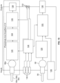
- Fig. 15 shows a plurality of representative light detectors 88, 88a.
- the lower detector 88 is associated with the reference fiber 90, as described above to form a feedback loop with the light source driver 100 to control the brightness of the light source 80.
- the upper light detector 88a of Fig. 15 is associated with one of the scanning fibers 90a-90c.
- Fig. 15 only shows one such detector 88a, but there may be one or more such detectors 88a for each scanning fiber 90a-90c provided in the optical sensor system 70.
- Each of these light detectors 88a receives the portion of the reflected beam 104 transmitted thereto by the associated scanning fiber 90a-90c. Each light detector 88a converts the light into a signal that may pass through one or more amplifiers 124 (e.g., a transimpedance amplifier, a gain amplifier, and/or a buffer amplifier), if provided.
- the individual signals represent a characteristic of the fluid (e.g., the location of its interface) or the nature of the fluid on the ramp 66 at the location monitored by the associated scanning fiber 90a-90c. For example, in one embodiment, as the ramp 66 comes into alignment with the optical sensor system 70, the detector(s) 88a will first sense light reflected through the plasma layer 58 on the ramp 66.
- a positive error signal indicates that the RBC layer 56 on the ramp 66 is too large (as Fig. 6 shows).
- the interface command module 128 generates a signal to adjust an operational parameter accordingly, such as by reducing the rate at which plasma is removed through a tube 130 associated with the first outlet port 30 under action of a pump 132 ( Fig. 16 ).
- the interface 60 moves away from the constricted passage 68 toward the desired control position (as Fig. 5 shows), where the error signal is zero.
- a negative error signal indicates that the RBC layer 56 on the ramp 66 is too small (as Fig. 7 shows).
- the interface command module 128 generates a signal to adjust an operational parameter accordingly, such as by increasing the rate at which plasma is removed through the first outlet port 30 and associated tube 130.
- the interface 60 moves toward the constricted passage 68 to the desired control position ( Fig. 5 ), where the error signal is again zero.
- the optical sensor system 70 may determine other information about the fluid in the blood separation chamber 22.
- the optical sensor system 70 may be configured to detect and read notations (e.g., bar codes) present on the centrifuge assembly 14 and/or the blood separation chamber 22.
- the optical sensor system 70 may be configured to gather spectrally-based information, thereby acting as a spectrometer. For example, when employing a white light source, different wavelengths of the light passing through the ramp 66 and fluid thereon will be absorbed by the different types of fluid that may appear on the ramp 66.
- the light that is reflected to a scanning fiber 90a-90c may be passed through a spectral beam splitter and then to a pair of light detectors 88a, with each detector receiving the unique wavelengths passed thereto and generating signals based on that data.
- the signals may be passed to a controller or processing module that considers the individual signals (e.g., considering red vs. blue light absorption) and/or compares them to historical signals (e.g., considering the difference in blue light absorption over time) to generate information about the fluid in the blood separation chamber 22 (e.g., lipid concentration, the presence of cellular blood components in separated plasma, platelet concentration, and hemolysis) and/or to cause adjustments in the operation of the system 10.
- the optical sensor system 70 may include additional or alternative components without departing from the scope of the present disclosure.
- Fig. 15 shows one or more power or status indicators 132 (which can be a visual indicator that the optical sensor system 70 is functional) and one or more voltage regulators 134 associated with the indicators 132, the driver 100, and various amplifiers 124.
- the system may also include various connectors 136 between the various components (e.g., BNC connectors, 3-pin connectors to a power source, etc.), as well as to other components that are not illustrated.
- centrifuge assemblies according to the present disclosure may be provided as umbilicus-driven (as illustrated in Figs. 1 and 2 ) or as direct-driven. If the centrifuge assembly is umbilicus-driven, additional steps may be taken to reduce the risk of the view of the ramp 66 by the optical sensor system 70 being blocked or obscured by the yoke 20 or umbilicus 38 during use.
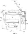
- a centrifuge assembly 14a having a modified yoke 20a is provided, as shown in Figs. 17-19 .
- the yoke 20a includes first and second support arms 200 and 202, which are shown as being generally diametrically opposed, with the centrifuge bowl 16 positioned therebetween.
- the yoke 20a is configured and operates generally according to the above description of the yoke 20 of Figs. 1 and 2 , with the exception that one of the support arms (illustrated as second support arm 202) defines an opening or aperture or window 204 therethrough.
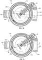
- the yoke window 204 is configured to provide a sight line through the support arm 202 to allow the optical sensor system 70 to view and monitor the ramp 66.
- the yoke window 204 is preferably significantly larger than the ramp 66 to maximize the visibility of the ramp 66 through the support arm 202, with a height H (the vertical dimension in the orientation of Fig. 17 ) that is greater than the height of the ramp 66 (shown in Fig. 17 as a pair of broken lines 206 to represent the multiple possible positions of the ramp 66 as the centrifuge bowl 16 is rotated) and a width or angular extent W ( Fig. 19 ) that is greater than the width or angular extent of the ramp 66.
- H the vertical dimension in the orientation of Fig. 17
- W Fig. 19
- the yoke window 204 is positioned with the ramp 66 centered along the height H of the yoke window 204 (i.e., with the vertical center of the ramp 66 being at the same elevation as the vertical center of the yoke window 204 in the orientation of Fig. 17 ), but it is also within the scope of the present disclosure for the ramp 66 to be closer to the top or bottom of the yoke window 204.
- the yoke window 204 preferably has a width or angular extent W equal to or greater than that of the opposing support arm 200 at the same elevation, with the other support arm 200 being diametrically opposed to the yoke window 204.
- the illustrated configuration may be preferred because of the fact that the yoke 20a rotates at one half the speed of the centrifuge bowl 16, as described above in greater detail. In such a rotational relationship, a 180° rotation of the yoke 20a will result in a 360° rotation of the centrifuge bowl 16.
- the ramp 66 will be at the same position (e.g., in position to be viewed by the optical sensor system 70) upon each 180° rotation of the yoke 20a. Accordingly, if the yoke is provided with visual obstructions or obstacles positioned 180° apart, then it may be that the view of the ramp 66 will be obstructed during consecutive 360° rotations of the centrifuge bowl 16.
- bracketing method is only one way of distinguishing between obstructed and unobstructed views of the ramp 66, and other methods of distinguishing between obstructed and unobstructed views of the ramp 66 may be employed without departing from the scope of the present disclosure.
- FIGs. 17-19 illustrate a two-armed yoke 20a, with one of the support arms 202 having a window 204 therethrough for improved visibility into the centrifuge bowl 16 from an externally located optical sensor system
- Fig. 20 shows only one support arm 302 of a yoke 20b. If the yoke 20b includes only one support arm 302, then the above-described concern of a visual obstruction located 180° away from the support arm 302 is effectively eliminated.
- a yoke 20b having an optical fiber bundle 300 associated therewith is provided.
- an optical fiber bundle 300 is secured to an exterior and/or an interior portion one of the yoke support arms 302, but it is also within the scope of the present disclosure for a single optical fiber bundle to be associated with two yoke support arms or for separate optical fiber bundles to be associated with each yoke support arm (if more than one support arm is provided).
- the optical fiber bundle 300 extends between a first or lower end 304 and a second or upper end 306.
- the lower end 304 is illustrated in greater detail in Figs. 21 and 22
- the upper end 306 is illustrated in greater detail in Fig. 23 .
- the optical fiber bundle 300 includes one or more of signal fibers 310 and one or more illumination fibers 312, all of which are configured to transmit light between the ends 304 and 306 of the optical fiber bundle 300.
- the signal fibers 310 are positioned at and directly adjacent to the central axis of the optical fiber bundle 300, while the illumination fibers 312 are positioned around the signal fibers 310, such as in a ring or annular arrangement.
- This configuration is advantageous when used in combination with the particular illumination and detection assembly 308 of Fig. 20 , but other fiber configurations (such as the mixed arrangement of signal fibers 310 and illumination fibers 312 shown in Fig. 23A or a configuration that positions the illumination fibers 312 at and directly adjacent to the central axis of the optical fiber bundle 300, with the signal fibers 310 positioned around the illumination fibers 312) may be employed with differently configured illumination and light detection assemblies.
- the illustrated illumination and detection assembly 308 comprises a central photodiode 314 or other suitable light detector aligned with the central axis of the optical fiber bundle 300 at its lower end 304 (to correspond to the location of the signal fibers 310 at and directly adjacent to the central axis of the optical fiber bundle 300) and a plurality of light-emitting diodes or laser diodes 316 or other suitable light sources arranged in a ring around the light detector 314 (to correspond to the location of the illumination fibers 312 at the lower end 304 of the optical fiber bundle 300).
- the light source(s) 316 may be spaced away from the light detector(s) 314 to prevent the light detector(s) 314 from receiving light from the light source(s) 316, in which case the lower end 304 of the optical fiber bundle 304 may be outwardly flared ( Figs. 21 and 22 ) to similarly separate the signal fibers 310 from the illumination fibers 310 and to maintain the fibers in proper registration with the associated components of the illumination and detection assembly 308.
- light is emitted by the light source(s) 316 in a direction substantially parallel to the rotational axis and received by the illumination fibers 310 at the lower end 304 of the optical fiber bundle 300.
- the illumination fibers 310 transmit the light to the upper end 306 of the optical fiber bundle 300, where it is directed onto the outer surface of the centrifuge bowl 16 in a generally radial direction, including the ramp 66 when it has rotated into light-receiving relationship with the upper end 306 of the optical fiber bundle 300.
- the light source(s) 316 may be configured to be always on or to only be on when the ramp 66 is in light-receiving relationship with the upper end 306 of the optical fiber bundle 300.
- Light from the illumination fibers 312 passes through the ramp 66 and the fluid thereon (as described above with respect to the embodiment of Figs. 1-16 ).
- the light is reflected back through the ramp 66 and out of the centrifuge bowl 16 (by a retroreflector or mirror or the like, as described above with respect to the embodiment of Figs. 1-16 ), where it is received by the signal fibers 310 at the upper end 306 of the optical fiber bundle 300.
- the signal fibers 310 transmit the reflected light from the upper end 306 of the optical fiber bundle 300 to the lower end 304 of the optical fiber bundle 300, where it is directed toward the light detector(s) 314.
- the light detector(s) 314 receives the light from the signal fibers 310 and transmits the data to a processor, such as the interface command module 126, for detecting and controlling the location of the interface on the ramp 66 and/or determining other information about the fluid on the ramp 66.
- a processor such as the interface command module 126
- a wide variety of information may be determined about the fluid processing region by providing two or more light sources 316 configured to emit light having differing wavelengths.
- the light sources 316 may operate simultaneously or be controlled to function separately (e.g, by switching selected light sources 316 on during one sampling session or rotation of the centrifuge bowl 16 and the switching those light sources 316 off and other light sources 316 on during another sampling session or rotation of the centrifuge bowl 16) to direct light of differing wavelengths into the fluid processing region, which different wavelengths may be used to determine different information about the fluid processing region (e.g., lipemia or hemolysis or the location of the interface, etc.).
- the light detector(s) 314 and the light source(s) 316 are all positioned at the same general location, which may be at a non-rotating surface of the centrifuge assembly 14b along the axis of rotation, but it is also within the scope of the present disclosure for the components to be located at different locations. It is also within the scope of the present disclosure for the illumination and signal fibers to be positioned at different locations.
- the illumination fibers 312 may be positioned as shown in Fig.
- the signal fibers 310 are at least partially positioned within the centrifuge bowl 16 to directly receive light from the illumination fibers 312 after it has passed through the ramp 66 (e.g., with the upper ends of the signal fibers 301 being located on the centrifuge spool behind the ramp 66, where the retroreflector or mirror would otherwise be to receive light transmitted through the ramp 66).
- the signal fibers 310 would then transmit the light from the illumination fibers 312 to the light detector 314, wherever it may be located.
- Optical sensor systems of the type illustrated in Fig. 20 have several advantages. For example, such a design takes advantage of the proximity of the optical fiber to the fluid processing region to implement a non-imaging light collection system. This allows for more generous alignment and focusing tolerances and illumination requirements in comparison to other known optical sensor systems. Additionally, on account of the light being directed into the fluid processing region from a position that rotates in the same direction as the fluid processing region, the signal received from the fluid processing region may be longer than a signal resulting from light directed into the fluid processing region from a stationary position (e.g., on the order of twice the duration).
- Systems of the type illustrated in Fig. 20 may be used alone or in combination with the other aspects described herein.
- the system of Fig. 20 may be used in combination with the optical sensor system 70 to act as an auxiliary optical sensor system in the event that the view of the optical sensor system 70 becomes obscured or obstructed or to monitor a different aspect of the fluid on the ramp 66.
Landscapes
- Health & Medical Sciences (AREA)
- Life Sciences & Earth Sciences (AREA)
- Engineering & Computer Science (AREA)
- General Health & Medical Sciences (AREA)
- Chemical & Material Sciences (AREA)
- Physics & Mathematics (AREA)
- Biomedical Technology (AREA)
- General Physics & Mathematics (AREA)
- Immunology (AREA)
- Analytical Chemistry (AREA)
- Pathology (AREA)
- Biochemistry (AREA)
- Hematology (AREA)
- Heart & Thoracic Surgery (AREA)
- Vascular Medicine (AREA)
- Animal Behavior & Ethology (AREA)
- Anesthesiology (AREA)
- Veterinary Medicine (AREA)
- Public Health (AREA)
- Cardiology (AREA)
- Food Science & Technology (AREA)
- Ecology (AREA)
- Urology & Nephrology (AREA)
- Medicinal Chemistry (AREA)
- Biophysics (AREA)
- Molecular Biology (AREA)
- External Artificial Organs (AREA)
- Investigating Or Analysing Materials By Optical Means (AREA)
- Centrifugal Separators (AREA)
Description
- The disclosure relates to blood treatment systems and methods. More particularly, the disclosure relates to systems and methods for optically detecting or monitoring characteristics of fluid (e.g., the location of an interface between separated blood components) within a centrifugal blood processing device.
- Various blood processing systems now make it possible to collect particular blood constituents, instead of whole blood, from a blood source. Typically, in such systems, whole blood is drawn from a blood source, the particular blood component or constituent is separated, removed, and collected, and the remaining blood constituents are returned to the blood source. Removing only particular constituents is advantageous when the blood source is a human donor, because potentially less time is needed for the donor's body to return to pre-donation levels, and donations can be made at more frequent intervals than when whole blood is collected. This increases the overall supply of blood constituents, such as plasma and platelets, made available for transfer and/or therapeutic treatment.
- Whole blood is typically separated into its constituents through centrifugation. This requires that the whole blood be passed through a centrifuge after it is withdrawn from, and before it is returned to, the blood source. To reduce contamination and possible infection (if the blood source is a human donor or patient), the blood is preferably processed within a sealed, sterile fluid flow system during the centrifugation process. Typical blood processing systems include a disposable, sealed, and sterile flow circuit, including a centrifuge chamber portion, that is mounted in cooperation on a durable, reusable assembly containing the hardware (centrifuge, drive system, pumps, valve actuators, programmable controller, and the like) that rotates a centrifuge chamber and controls the flow through the fluid circuit.
- The centrifuge rotates the centrifuge chamber of the disposable flow circuit during processing. As the centrifuge chamber is rotated by the centrifuge, the heavier (greater specific gravity) components of the whole blood in the centrifuge chamber, such as red blood cells, move radially outwardly away from the center of rotation toward the outer or "high-G" wall of the centrifuge chamber. The lighter (lower specific gravity) components, such as plasma, migrate toward the inner or "low-G" wall of the centrifuge chamber. The boundary that forms between the denser red blood cells and the lighter plasma in the centrifuge chamber is commonly referred to as the interface. Various ones of these components can be selectively removed from the whole blood by providing appropriately located channeling structures and outlet ports in the flow circuit. For example, in one blood separation procedure, plasma is separated from cellular blood components and collected, with the cellular blood components and a replacement fluid being returned to the blood source. Alternatively, red blood cells may be harvested from the centrifuge chamber and the rest of the blood constituents returned to the donor. Other processes are also possible including, without limitation, platelet collection, red blood cell exchanges, plasma exchanges, etc. In these procedures, the efficiency of the process is often dependent upon accurate identification and control of the position of the interface during centrifugation.
- It is known to employ an optical sensor system to monitor the flow of blood and/or blood components through the flow circuit in the centrifuge and determine various characteristics of the flow. For example,
U.S. Patent No. 6,899,666 to Brown relates to an optical sensor system for viewing into the centrifuge chamber for detecting and controlling the location of an interface between separated blood components in a centrifuge. While this system functions satisfactorily, there remains an opportunity to provide optical monitoring systems with improved interface detection and greater robustness. -
US 2009/129976 A1 describes a circuit for collecting a blood component includes a blood collection device provided with a blood collection needle through which blood is collected from a blood donor, a blood separator in which the blood collected by the above blood collection device is separated, a blood component collection bag in which a predetermined blood component separated by the above blood separator is collected, a blood line in which the blood collection needle is connected to an inlet of the blood separator, a line for removing an initial blood flow, which branches from a first branching portion formed in the blood line, and in which an initial flow of blood collected from the blood donor is removed, and an anticoagulant-injection line that branches from a second branching portion, formed in the line for removing the initial blood flow, and into which an anticoagulant is injected. - In one aspect, a blood processing system is provided in accordance with any of claims 1-10.
- In another aspect, a method is provided for monitoring fluid within a blood processing system having a centrifuge assembly, in accordance with any of claims 11-15.
- The optical sensor system can include a light source, a light detector, and an optical fiber providing a light path between the light source and the light detector.
- The optical sensor system may include a white light source.
- The optical sensor system is configured to emit a scanning light beam along a path toward the light-transmissive portion of the centrifuge assembly substantially parallel to, but off-set from, a radial line perpendicular to and passing through the rotational axis of the centrifuge assembly. The path of the scanning light beam is oriented so as to not pass through the rotational axis of the centrifuge assembly. The method includes directing a scanning light beam from an optical sensor system secured to a fixture of the blood processing system along a path substantially parallel to, but off-set from, a radial line perpendicular to and passing through the rotational axis of the centrifuge assembly, but oriented so as to not pass through the rotational axis of the centrifuge assembly, toward and into the centrifuge assembly so as to intersect the blood or at least one of the blood components. At least a portion of the scanning light beam is reflected after intersecting the blood or at least one of the blood components.
- The centrifuge assembly can include a yoke including a first support arm configured to rotate the light-transmissive portion and the fluid processing region about the rotational axis, the yoke being positioned between the light-transmissive portion and the optical sensor system and is configured to allow passage of at least a portion of the light through the first support arm as the light is directed toward the light-transmissive portion.
- An optical fiber bundle can extend between first and second ends being associated with the support arm of the yoke. The optical sensor system can be configured to direct a light toward the first end of the optical fiber bundle. The second end of the optical fiber bundle directs the light toward the light-transmissive portion.
-
-
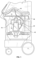
Fig. 1 is a side elevation view, with portions broken away and in section, of one example of a blood separation system employing aspects of the present invention, with a centrifuge bowl and spool of the system being shown in their operating position; -
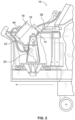
Fig. 2 is a side elevation view, with portions broken away and in section, of the system shown inFig. 1 , with the bowl and spool shown in an upright position for receiving a blood separation chamber; -
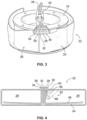
Fig. 3 is a top perspective view of the spool of the centrifuge shown inFig. 2 in its upright position and carrying the blood separation chamber; -
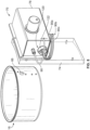
Fig. 4 is a plan view of the blood separation chamber shown inFig. 3 , out of association with the spool; -
Fig. 5 is an enlarged perspective view of an interface ramp carried by the centrifuge in association with the blood separation chamber, showing the centrifugally separated red blood cell layer, plasma layer, and interface within the chamber when in a desired location on the ramp; -
Fig. 6 is an enlarged perspective view of the interface ramp shown inFig. 5 , showing the red blood cell layer and interface at an undesired high location on the ramp; -
Fig. 7 is an enlarged perspective view of the interface ramp shown inFig. 5 , showing the red blood cell layer and interface at an undesired low location on the ramp; -
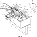
Fig. 8 is a front perspective view of the bowl of the centrifuge ofFig. 1 and an optical sensor system or assembly, inverted from the usual operating position for clarity, which may form a part of an interface controller to view the interface ramp during rotation of the bowl; -
Fig. 9 is a rear perspective view of the bowl and optical sensor system or assembly ofFig. 8 ; -
Fig. 10 is a cross-sectional view of the optical sensor system or assembly ofFig. 8 ; -
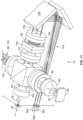
Fig. 11 is a perspective view of selected internal components of the optical sensor system or assembly ofFig. 8 , with a housing or case of the optical sensor assembly omitted for illustrative purposes; -
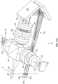
Fig. 11A is a perspective view of an alternative embodiment of the selected internal components of the optical sensor system ofFig. 11 ; -
Fig. 11B is a perspective view of another alternative embodiment of the selected internal components of the optical sensor system ofFig. 11 ; -
Fig. 12 is a top plan view of the bowl and optical sensor system or assembly ofFig. 8 , with a housing or case of the optical sensor system omitted for illustrative purposes; -
Figs. 13 and14 illustrate a light beam from the optical sensor system ofFig. 8 passing through the interface ramp of the centrifuge bowl and a centrifuge container or other fluid passage containing blood or blood components; -
Fig. 15 is a schematic view of the interconnectivity of selected electronic components of the optical sensor system ofFig. 8 ; -
Fig. 16 is a schematic view of the interface controller, incorporating the optical sensor system ofFig. 8 ; -
Fig. 17 is a perspective view of an alternative centrifuge yoke for use with optical sensor systems according to the present disclosure; -
Figs. 18 and 19 are cross-sectional views of the centrifuge and yoke ofFig. 17 , showing sight lines into the centrifuge in different centrifuge positions; -
Fig. 20 is a partial cross-sectional view of another embodiment of an alternative centrifuge yoke for use with optical sensor systems according to the present disclosure; -
Fig. 21 is a cross-sectional detail view of a lower end of an optical fiber bundle associated with the yoke ofFig. 20 ; -
Fig. 22 is an end view of the lower end of the optical fiber bundle associated with the yoke ofFig. 20 ; -
Fig. 23 is an end view of the upper end of the optical fiber bundle associated with the yoke ofFig. 20 ; and -
Fig. 23A is an end view of an alternative embodiment of the upper end of the optical fiber bundle associated with the yoke ofFig. 20 . - The embodiments disclosed herein are for the purpose of providing a description of the present subject matter, and it is understood that the subject matter may be embodied in various other forms and combinations not shown in detail. Therefore, specific embodiments and features disclosed herein are not to be interpreted as limiting the subject matter as defined in the accompanying claims.
-
Figs. 1 and2 show a centrifugalblood processing system 10 with an interface controller 12 (Fig. 16 ) having improved interface detection capabilities. The illustratedsystem 10 shares many centrifuge design aspects with a system currently marketed as the AMICUS® separator by Fenwal, Inc. of Lake Zurich, Illinois, as described in greater detail inU.S. Patent No. 5,868,696 . Thesystem 10 can be used for processing various fluids, but is particularly well suited for processing whole blood, blood components, or other suspensions of biological cellular materials. - While interface control and optical detection principles will be described herein with reference to one
particular system 10 andcentrifuge assembly 14, it should be understood that these principles may be employed with other fluid processing systems (e.g., other centrifugal blood separation systems and centrifuges) without departing from the scope of the present disclosure. - The
system 10 includes acentrifuge assembly 14 used to centrifugally separate blood components. Thesystem 10 may be programmed to separate blood into a variety of components (e.g., platelet concentrate, platelet-rich plasma, and red cells). It may be used for platelet collection, therapeutic plasma exchange, red cell exchange, red cell or plasma collection, or other blood processing applications. For illustrative purposes only, a platelet collection procedure and a therapeutic plasma exchange procedure will be described herein. However, the principles described and claimed herein may be employed with other blood separation procedures without departing from the scope of the present disclosure. - The illustrated
centrifuge assembly 14 shares certain design aspects with the one shown inU.S. Patent No. 5,316,667 to Brown et al. The illustrated centrifuge assembly, which is shown for purposes of illustration and not limitation, comprises abowl 16 and aspool 18. In one embodiment, thebowl 16 andspool 18 are pivoted on ayoke 20 between an operating position (Fig. 1 ) and a loading/unloading position (Fig. 2 ). Other methods of accessing thebowl 16 and thespool 18 may also be employed without departing from the scope of the present disclosure. The present subject matter may be used with centrifuges that do not employ such a spool and bowl, such as molded centrifuge chambers, centrifuge bowls with pre-formed processing chamber slots, or other designs. - When in the loading/unloading position, the
spool 18 can be opened by movement at least partially out of thebowl 16, asFig. 2 shows. In this position, the operator wraps a flexible blood separation chamber 22 (seeFig. 3 ) about thespool 18. Closure of thespool 18 andbowl 16 encloses thechamber 22 between the inner surface of thebowl 16 and the outer surface of the spool 18 (which collectively define the fluid processing region in which thechamber 22 is received) for processing. When closed, thespool 18 andbowl 16 are pivoted into the operating position ofFig. 1 for rotation about a rotational axis. - The
blood separation chamber 22 can be variously constructed.Fig. 4 shows a representative embodiment. - The
chamber 22 shown inFig. 4 allows for either single- or multi-stage processing. When used for multi-stage processing of whole blood, afirst stage 24 separates whole blood into first and second components. Depending on the nature of the separation procedure, one of the components may be transferred into asecond stage 26 for further processing. - As
Figs. 3 and 4 best show, there are threeports first stage 24. Depending on the particular blood processing procedure, the ports may have different functionality but, in an exemplary procedure, the port identified at 32 may be used for conveying blood (which may include anticoagulant) from a blood source or donor into thefirst stage 24. During such a procedure, the other twoports first stage 24. For example, thefirst outlet port 30 may convey a low density blood component from thefirst stage 24, while thesecond outlet port 28 may convey a high density blood component from thefirst stage 24. - In a method of carrying out single-stage processing, one of the separated components is returned to the donor, while the other is removed from the
first stage 24 and stored. For example, when carrying out a therapeutic plasma exchange procedure, whole blood in thefirst stage 24 is separated into cellular components (i.e., a high density red blood cell component) and substantially cell-free plasma (i.e., a low density component). The plasma is removed from thefirst stage 24 via thefirst outlet port 30 for collection and storage, while the cellular components are removed from thefirst stage 24 via thesecond outlet port 28 and returned to the donor or patient. Alternatively, rather than collecting and storing the plasma, it may instead be discarded after separation or treated by a secondary device and returned to the donor or patient. - If multi-stage processing is required, for example in a platelet collection procedure, one of the components (platelet-rich plasma) will be transferred from the
first stage 24 to thesecond stage 26 via aport 34 associated with thesecond stage 26. The component transferred to thesecond stage 26 is further fractionated into sub-components such as plasma and platelet concentrate, with one of the sub-components (plasma in one embodiment) being removed from thesecond stage 26 via anoutlet port 36 and the other sub-component (platelet concentrate in one embodiment) remaining in thesecond stage 26. In the illustrated embodiment, theports chamber 22. - While the
same ports first stage 24 are used as in the above-described therapeutic plasma exchange procedure, theports first stage 24 via theport 28 and is separated into red blood cells (i.e., the high density blood component) and platelet-rich plasma (i.e., the low density blood component). The red blood cells are returned to the donor (via the port 32), while the platelet-rich plasma is conveyed out of the first stage 24 (via the first outlet port 30) and into the second stage 26 (via the inlet port 34). In thesecond stage 26, the platelet-rich plasma is separated into platelet-poor plasma and platelet concentrate. The platelet-poor plasma is removed from the second stage 26 (via the outlet port 36), leaving platelet concentrate in thesecond stage 26 for eventual resuspension and transfer to one or more storage containers. - As best shown in
Fig. 3 , atubing umbilicus 38 is attached to theports second stages Figs. 1 and2 ). AsFig. 1 shows, a non-rotating (zero omega)holder 40 holds the upper portion of the umbilicus 38 in a non-rotating position above thespool 18 andbowl 16. Aholder 42 on theyoke 20 rotates the mid-portion of the umbilicus 38 at a first (one omega) speed about the suspendedspool 18 andbowl 16. Another holder 44 (Figs. 2 and3 ) mounts the lower end of the umbilicus 38 to thecentrifuge assembly 14. The inherent strength of the umbilicus 38 causes thecentrifuge assembly 14 to rotate at a second speed twice the one omega speed (the two omega speed). This known relative rotation of theumbilicus 38 keeps it from accumulating twisting, in this way avoiding the need for rotating seals. In an alternative embodiment, rather than theholder 42 rotating the umbilicus 38 to turn thecentrifuge assembly 14, a gear system may be employed to rotate theumbilicus 38 and/or thecentrifuge assembly 14 separately. It should be noted that the present subject matter can also be employed in direct-drive centrifuge assemblies (i.e., systems that rely on a gear train to rotate the centrifuge) and centrifuge assemblies using rotating seals, and is not limited to use in a seal-less centrifuge system. - As
Fig. 4 shows, a firstinterior seal 46 is located between the lowdensity outlet port 30 and the highdensity outlet port 28. A secondinterior seal 48 is located between the highdensity outlet port 28 and theblood inlet port 32. The interior seals 46 and 48 form a fluid passage 50 (an inlet for whole blood in an exemplary platelet collection procedure or an outlet for high density blood components in an exemplary therapeutic plasma exchange procedure) and a lowdensity collection region 52 in thefirst stage 24. Thesecond seal 48 also forms a fluid passage 54 (an outlet for high density blood components in an exemplary platelet collection procedure or a blood inlet in an exemplary therapeutic plasma exchange procedure) in thefirst stage 24. - In a platelet collection procedure, the
fluid passage 50 channels blood into thefirst stage 24, where it separates into an optically dense layer 56 (Fig. 5 ), which forms as larger and/or heavier blood particles move under the influence of centrifugal force toward the high-G (outer)wall 62. The opticallydense layer 56 will include red blood cells (and, hence, may be referred to herein as the "RBC layer") but, depending on the speed at which theassembly 14 is rotated, other cellular components (e.g., larger white blood cells) may also be present in theRBC layer 56. - Rather than flowing blood into the
first stage 24 by the fluid passage 50 (as in a platelet collection procedure), blood enters thefirst stage 24 by thefluid passage 54 in a therapeutic plasma exchange procedure, but is still separated into anRBC layer 56. In comparison to a platelet collection procedure, thecentrifuge assembly 14 rotates at a higher speed during a therapeutic plasma exchange procedure, creating a stronger separation field in thefirst stage 24. As a result of the stronger separation field, additional cellular components, namely white blood cells and platelets, will be present in a greater quantity in theRBC layer 56. - In both cases, the movement of the component(s) of the
RBC layer 56 displaces less dense blood components radially toward the low-G (inner)wall 64, forming a second, less opticallydense layer 58. In an exemplary platelet collection procedure, the less opticallydense layer 58 includes platelet-rich plasma (and, hence, will be referred to herein as the "plasma layer"). In an exemplary therapeutic plasma exchange procedure, the less opticallydense layer 58 includes substantially cell-free plasma. However, depending on the speed at which thecentrifuge assembly 14 is rotated and the length of time that the blood is resident in the centrifuge assembly, other components (e.g., smaller white blood cells) may also be present in theplasma layer 58. - The transition between the
RBC layer 56 and theplasma layer 56 is generally referred to as the interface 60 (Fig. 5 ). Platelets and white blood cells (which have a density greater than plasma and usually less than red blood cells) typically occupy this transition region, although that also varies with centrifuge speed and residence time, as is well known in the technical field. - The location of the
interface 60 within thechamber 22 can dynamically shift during blood processing, asFigs. 6 and 7 show. If the location of theinterface 60 is too high (that is, if it is too close to the low-G wall 64 and theremoval port 30, asFig. 6 shows), cellular components can spill over and into the lowdensity collection region 52, potentially adversely affecting the quality of the low density components (typically plasma). On the other hand, if the location of theinterface 60 is too low (that is, if it resides too far away from the low-G wall 64, asFig. 7 shows), the collection efficiency of thesystem 10 may be impaired. - In the illustrated embodiment, as
Fig. 5 shows, aramp 66 extends from the high-G wall 62 of thebowl 16 at an angle "A" across the lowdensity collection region 52. The angle "A," measured with respect to the axis of thefirst outlet port 30 is about 25° in one embodiment.Fig. 5 shows the orientation of theramp 66 when viewed from the low-G wall 64 of thespool 18.Fig. 4 shows, in phantom lines, the orientation of theramp 66 when viewed from the high-G wall 62 of thebowl 16. - Further details of the angled relationship of the
ramp 66 and thefirst outlet port 30 can be found inU.S. Patent No. 5,632,893 to Brown et al. , which is incorporated herein by reference. Theramp 66 shown inFigs. 5-7 may be considered a simplified or representational version of an actual ramp that would be used in practice. For example,Figs. 8-9 and13-14 illustrate a particular ramp configuration that may be particularly advantageous for imaging and interface-detection purposes, as will be described in greater detail below. However, theramp 66 may be variously configured without departing from the scope of the present disclosure. - The
ramp 66 forms a tapered wedge that restricts the flow of fluid toward thefirst outlet port 30. The top edge of theramp 66 extends to form aconstricted passage 68 along the low-G wall 64. Theplasma layer 58 must flow through the constrictedpassage 68 to reach thefirst outlet port 30. - As
Fig. 5 shows, theramp 66 makes theinterface 60 between theRBC layer 56 and theplasma layer 58 more discernible for detection, displaying theRBC layer 56,plasma layer 58, andinterface 60 for viewing through a light-transmissive portion of the high-G wall 62 of thechamber 22, as will be described in greater detail below. - Further details of the
separation chamber 22 and its operation may be found inU.S. Patent No. 5,316,667 . - In one embodiment, the interface controller 12 (
Fig. 16 ) includes an optical sensor system or assembly 70 (seeFigs. 8-12 ) positioned at a location outside of thecentrifuge assembly 14. Theoptical sensor system 70 is oriented to detect the location of theinterface 60 theRBC layer 56 and theplasma layer 58 on theramp 66. If theinterface 60 detected by theoptical sensor system 70 is at an improper location (e.g., in the locations ofFigs. 6 or 7 ), theinterface controller 12 is functional to correct the location of theinterface 60, as will be described in greater detail herein. - Referring to
Figs. 8-12 , theoptical sensor system 70 is secured to a fixture orwall 74 of thesystem 10. Thewall 74 includes an opening 76 (Fig. 9 ) through which light from theoptical sensor system 70 may be directed toward and into thecentrifuge assembly 14 via a light-transmissive portion thereof. In the illustrated embodiment, theramp 66 is translucent and comprises the light-transmissive portion of thecentrifuge bowl 16, such that light from theoptical sensor system 70 passes through the ramp 66 (Figs. 13 and14 ) to intersect the separated blood components thereon to determine the location of theinterface 60, as will be described in greater detail herein. - The
optical sensor system 70 includes a variety of components, some of which are contained within a housing orcase 78. Among the components mounted within thehousing 78 is at least one light source 80 (Figs. 10-12 ), which emits asource beam 82 of light. Theoptical sensor system 70 may include one or more components (e.g., the achromatic prism pairs 84 and aperture stop 86 ofFigs. 10-12 ) configured to condition and/or focus thesource beam 82 that exits thelight source 80. For example, if provided, anachromatic prism pair 84 provides a color correction function by directing two color wavelengths (e.g., blue and red) along a desired path or angle, while anaperture stop 86 controls and limits the amount of light from thelight source 80 allowed to pass further through theoptical sensor system 70. It should be understood that, depending on the nature of thelight source 80, selected components (e.g., the achromatic prism pairs 84) may be omitted from theoptical sensor system 70. Similarly, additional components may also be incorporated into theoptical sensor system 70 without departing from the scope of the present disclosure. - In the illustrated embodiment, the
light source 80 comprises a light-emitting diode which emits a sourcelight beam 82 or a plurality of light-emitting diodes that combine to emit a sourcelight beam 82. Thelight source 80 may emit a single- or multiple-wavelength sourcelight beam 82, but in a preferred embodiment, comprises a white light source that is configured to emit a multi-wavelength, white sourcelight beam 82. If provided as a white light source, thelight source 80 may comprise one or more true white lights (e.g., incandescent or filament lights or light-emitting diodes) or a plurality of differently colored light sources (e.g., red, green, and blue light-emitting diodes arranged on a common die) that combine to simulate or approximate a white light. In one embodiment, thelight source 80 is of the type which emits a white sourcelight beam 82 exhibiting a relatively high spectral power distribution in the red and blue wavelength spectra, such as a warm white LUXEON® light-emitting diode of Philips Lumileds Lighting Company of San Jose, California. - In other embodiments, other types of light sources and source beams may be employed without departing from the scope of the present disclosure. For example, in another embodiment, the light source comprises one or more non-white, narrow spectrum light sources. The nature of the narrow spectrum light sources (e.g., whether they are provided as light-emitting diode or in some other form) and the source light beam emitted by the narrow spectrum light sources (e.g., the color of the light, if it is within the visible spectrum) may vary and is not limited to a particular type of light source or a particular wavelength of light. In one exemplary embodiment, a narrow spectrum light source comprises a light-emitting diode configured to emit a red source light beam, in which case the light source may be provided as a deep red LUXEON® light-emitting diode of Philips Lumileds Lighting Company of San Jose, California. Other narrow spectrum red light sources may also be employed, as well as other narrow spectrum light sources configured to emit a beam having any other suitable wavelength. If the light source is configured to emit a relatively wide bandwidth source beam, it may be preferred to also provide one or more filters configured to narrow the bandwidth of either the source beam emitted by the light source and/or the bandwidth of a light beam returning to the
optical sensor system 70 after having interacted with the fluid processing region. - The
optical sensor system 70 also includes a plurality oflight detectors Fig. 15 ). Thelight detectors light detectors housing 78, and may be mounted in a separate housing. This may be advantageous for the purpose of spacing thelight detectors centrifuge assembly 14. Additionally, such a configuration allows for a compact optical module design, which is relatively immune to electrical noise and vibration while allowing for electrically immune light transmission from the optical module to a separate electronics module that can be modified and upgraded for different functionality without affecting the optical module design. For example, if not otherwise provided, a separate electronics module could be modified and upgraded to include spectral splitting and analysis without modifying the optical module. - In embodiments having the
light detectors housing 78, they may be in communication with the interior of thehousing 78 via optical fibers 90-90c (Figs. 8-10 and15 ). In the illustrated embodiment, there are four optical fibers 90-90c (one referred to herein as areference fiber 90 and the others referred to herein asscanning fibers 90a-90c) extending between thehousing 78 and fourlight detectors Fig. 15 is simplified to show only onedetector 88a, but in the illustrated embodiment there are a plurality, preferably three or six, ofsuch detectors 88a). However, in other embodiments, there may be a different number of optical fibers and light detectors, at least one and preferably a plurality, such as three or more. For example, a beam splitter may be positioned at a downstream end of an optical fiber to split a beam exiting the optical fiber into two beams, with each beam going to a different light detector. - In the illustrated embodiment, the upstream or inlet (light-receiving) ends of the optical fibers 90-90c are oriented at an angle to the initial direction 92 of the source
light beam 82, as shown inFigs. 10-12 . In one embodiment, the upstream or inlet ends of the optical fibers 90-90c are positioned to receive light along a direction perpendicular to the initial direction 92 of the sourcelight beam 82. The optical fibers 90-90c are configured to receive at least a portion of the light emitted by thelight source 80, so selected components of theoptical sensor system 70 may be configured to direct light from thelight source 80 toward one or more of the optical fibers 90-90c. For example, in the illustrated embodiment, theoptical sensor system 70 includes abeam splitter 94 that is configured to split thesource beam 82 from thelight source 80 into two beams 96 (reference beam or first split beam) and 98 (scanning beam or second split beam) (Figs. 11 and12 ). In one embodiment, thebeam splitter 94 comprises a beam splitter cube which splits thesource beam 82, with afirst split beam 96 being a reference beam that is reflected at an angle (e.g., 90° in the illustrated embodiment) toward theoptical fiber 90 and asecond split beam 98 being a scanning beam that is transmitted through thebeam splitter cube 94 and toward thecentrifuge assembly 14. - The
optical sensor system 70 may include one or more components (e.g., anachromatic prism pair 84 for color correction, as shown inFigs. 10-12 ) configured to condition and/or focus thereference beam 96 before it reaches the associatedoptical fiber 90, but the light received by theoptical fiber 90 is essentially a direct view of the source beam 82 (albeit at a fraction of its original intensity) and gives an indication of the power level of thelight source 80. For this reason, theoptical fiber 90 that receives thereference beam 96 may be referred to as the reference fiber. As such, thereference fiber 90 may be associated with alight detector 88 that forms a feedback loop with adriver 100 of the light source 80 (Fig. 15 ). It may be advantageous for thelight source 80 to emit asource beam 82 having a substantially uniform or constant brightness, and any fluctuations in the brightness of thesource beam 82 are directly reflected in the brightness of thereference beam 96 and, hence, the strength of the signal transmitted from thelight detector 88 to thedriver 100. Thedriver 100 or a controller may make adjustments to the power delivered to thelight source 80 to maintain the brightness of thesource beam 82 at a substantially uniform level. In other embodiments, the brightness of thesource beam 82 may be measured and used as an input to measure fluid characteristics (e.g., lipemia or hemolysis), apart from or in addition to the brightness being controlled. It is also within the scope of the present disclosure for the brightness to be measured to determine light output degradation over time, either apart from or in addition to the brightness being controlled. Thelight detector 88 may be directly associated with thedriver 100 or, as shown inFig. 15 , include one or more intermediate devices (e.g., an interface processing module 126) that may measure or condition or otherwise interact with the signal from thelight detector 88 prior to reaching thedriver 100 or otherwise use the signal for other purposes. - In an alternative embodiment, the
reference fiber 90 is eliminated and thelight detector 88 that is positioned downstream of thereference fiber 90 in the above-described embodiment is instead positioned within thehousing 78. For example,Fig. 11A shows an embodiment in which thelight detector 88 is placed in substantially the same location and in the same orientation as thereference fiber 90 inFigs. 10 and11 . In such an embodiment, thelight detector 88 directly receives light, rather than having light transmitted thereto by thereference fiber 90. By such a configuration, other components of the optical sensor system 70 (e.g., lens 84) may also be eliminated or modified. In other embodiments, one or more of the otheroptical fibers 90a-90c may be eliminated and replaced with a light detector that is positioned in the same or a similar position and orientation in thehousing 78. - In another alternative embodiment which omits the
reference fiber 90, thelight detector 88 is placed in a different location within the housing 78 (Fig. 11B ), rather than being positioned at the location of thereference fiber 90 inFigs. 10 and11 . In the embodiment ofFig. 11B , thelight detector 88 is positioned adjacent to thelight source 80, which may include being positioned on the same printed circuit board as the light source 80 (if thelight source 80 is mounted on a printed circuit board), but may include any other suitable location. By such a configuration, other components of the optical sensor system 70 (in addition to the reference fiber 90) may be eliminated or modified, as appropriate. - Depending on the exact location of the
light detector 88, its orientation may vary, provided that it is oriented so as to be in at least partial light-receiving relationship with respect to thelight source 80. In one embodiment, thelight detector 88 is oriented at an angle with respect to the general path of thesource beam 82. In the illustrated embodiment, a substantially side-lookinglight detector 88 is provided, with thelight detector 88 being oriented generally perpendicular to the path of thesource beam 82. In other embodiments, thelight detector 88 may be positioned elsewhere within thehousing 78 and oriented differently, but it has been found that a side-lookinglight detector 88 positioned adjacent to thelight source 80 is particularly advantageous in terms of monitoring and controlling the level of light emitted by thelight source 80. - Regardless of the exact location of the optical fibers and/or light detectors, the
scanning beam 98 is transmitted through the beam splitter 94 (or other suitable light-directing member) and toward thecentrifuge assembly 14. Thescanning beam 98 may pass through a lens orprotective window 102 prior to reaching thecentrifuge assembly 14. Thewindow 102 may serve a number of purposes, which may include focusing thescanning beam 98 at the proper location of thecentrifuge assembly 14 and/or protecting the components of theoptical sensor system 70 contained within thehousing 78 from debris present within thesystem 10. As will be described in greater detail herein, thescanning beam 98 passes through theinterface ramp 66 and the fluids positioned thereon (including the interface 60) before being reflected back to theoptical sensor system 70. The reflected second split beam or reflectedscanning beam 104 passes through thewindow 102 and encounters thebeam splitter 94, which directs at least a portion of the reflectedscanning beam 104 at an angle to the path 92 of the scanning beam 98 (Fig. 12 ). The path 92 of thescanning beam 98 coincides with the direction in which the reflectedscanning beam 104 returns to the optical sensor system 70 (as well as the initial direction of the source light beam 82). In the illustrated embodiment, thebeam splitter 94 directs at least a portion of the reflectedsecond scanning 104 at a 90° angle to the path 92 of thescanning beam 98. Hence, it will be seen that the reflectedscanning beam 104 is directed in the opposite direction of thereference beam 96 by thebeam splitter 94. - In one embodiment, one or more
optical fibers 90a-90c may be positioned to directly receive the reflectedscanning beam 104 from the beam splitter 94 (i.e., being positioned along or adjacent to the same axis as thereference fiber 90, but oriented on the opposite side of thebeam splitter 94 and facing the opposite direction). In another embodiment, such as the one illustrated inFigs. 8-11 , the optical fiber(s) 90a-90c configured to receive the reflected scanning beam 104 (which may be referred to as scanning fibers) are positioned generally adjacent to thereference fiber 90. More particularly, the illustratedscanning fibers 90a-90c are positioned below and in the same plane as thereference fiber 90, on the same side of thebeam splitter 94 and facing in the same direction. Such a configuration may be advantageous for a number of reasons, such as space considerations and accessibility of the fibers for maintenance, replacement, and/or upgrade purposes. An optical barrier or other shielding surface may be interposed between thereference fiber 90 and thescanning fibers 90a-90c to prevent thereference beam 96 from illuminating thescanning fibers 90a-90c or the reflectedscanning beam 104 illuminating thereference fiber 90. - In the illustrated embodiment, to facilitate the fiber positioning described above, a beam directing member 106 (e.g., a pair of mirrors) is employed between the
beam splitter 94 and thescanning fibers 90a-90c to direct the reflectedscanning beam 104 to thescanning fibers 90a-90c. Theoptical sensor system 70 may include one or more components (e.g., the achromatic prism pairs 84,direct vision prism 108, and aperture stop 86 ofFigs. 10-12 ) configured to condition and/or focus the reflectedscanning beam 104 prior to encountering thebeam directing member 106. Adirect vision prism 108 may be particularly advantageous for undoing any dispersion of a reflected beam having passed through the ramp 66 (which may be prismatic, as described below), thereby color-correcting the reflected beam. - As for the relative position of the
optical sensor system 70 with respect to thecentrifuge assembly 14,Fig. 12 shows that the path 92 of thescanning beam 98 is parallel to, but offset from, a radial line perpendicular to and passing through therotational axis 110 of thecentrifuge assembly 14. Hence, it can be seen that the beam emitted by theoptical sensor system 70 to analyze the blood and/or blood components in thecentrifuge assembly 14 neither passes through nor is parallel to therotational axis 110 of thecentrifuge assembly 14. This may be advantageous depending on the configuration of theramp 66. For example,Figs. 13 and14 are cross-sectional views of theramp 66, which shows it with an angledinner face 112 and an angledouter face 114, which effectively make the ramp 66 a prism. As used in reference to the faces of theramp 66, the term "angled" refers to the fact that the inner and outer faces of theramp 66 are non-tangential to the substantially circular perimeter of thebowl 16. - In the illustrated embodiment, the
inner ramp face 112 is angled at approximately 29° (from a horizontal line, in the orientation ofFigs. 13 and14 ) and theouter ramp face 114 is angled at approximately 26.4° (from a horizontal line, in the orientation ofFigs. 13 and14 ), resulting in an approximately 55.4° prism. To minimize ghosting (show inFig. 14 as rays 116) and maintain focus of light through theramp 66 in view of the material (which may be a polycarbonate material in one embodiment) and configuration of the ramp 66 (i.e., as a prism), it has been found that causing thescanning beam 98 to encounter theouter ramp face 114 at an angle is advantageous. By offsetting the path 92 of the scanning beam 92 from therotational axis 110 of thecentrifuge assembly 14, theramp 66 will be at an angle to the path 92 when thescanning beam 98 encounters theouter ramp face 114. In one embodiment, theramp 66 is approximately 10° from center (seeFig. 12 ) when it comes into the field of vision of theoptical sensor system 70. In other embodiments, it may be advantageous for theramp 66 to be at a different angle or even centered when it comes into the field of vision of theoptical sensor system 70. - As for the individual faces of the
ramp 66, theinner ramp face 112 is angled to display the location of theinterface 60, as described in greater detail above with respect toFigs. 5-7 . Accordingly, it is theinner ramp face 112 that thescanning beam 98 is focused upon to detect the location of theinterface 60. Theouter ramp face 114 is angled to contribute to focusing thescanning beam 98 on theinner ramp face 112 at all times that theramp 66 is within the field of vision of theoptical sensor system 70. Depending on the configuration of theoptical sensor system 70, multiple samples or readings (of the order of one hundred, in some embodiments) can be taken each time theramp 66 rotates through the field of view of theoptical sensor system 70.Figs. 13 and14 illustrate two exemplary positions of theramp 66 during a single pass of theramp 66 through the field of vision of theoptical sensor system 70, withFig. 13 showing a portion of the right side of theinner ramp face 112 being scanned or viewed andFig. 14 showing a portion of the left-center side of theinner ramp face 112 being scanned or viewed. It will be seen that, in both positions, thescanning beam 98 is focused on theinner ramp face 112, where theinterface 60 is displayed. - As shown in
Figs. 13 and14 and noted above, at least a portion of the source beam 82 (which takes the form of thescanning beam 98 in the illustrated embodiment) is directed toward the rotatingbowl 16 to pass through the light-transmissive portion thereof, theramp 66, and the blood or blood component displayed thereon. In the illustrated embodiment, thebowl 16 is transparent to the light emitted by thelight source 80 only in the region at which theinterface ramp 66 is incorporated into the bowl 16 (Figs. 8 and12 ). In the illustrated embodiment, the region comprises a window or opening cut out in thebowl 16, which receives at least a portion of theramp 66. The remainder of thebowl 16 that passes through the path of theoptical sensor system 70 comprises an opaque or light absorbing material. In the illustrated embodiment, theoptical sensor system 70 remains stationary during operation of theblood processing system 10, as thespool 18 andbowl 16 rotate at a two omega speed. Thus, theoptical sensor system 70 may be provided as a continuous or an always-on system (i.e., shining light on thecentrifuge assembly 14 even when theramp 66 is out of the field of vision of the optical sensor system 70) or as an intermittent or gated system that only emits a source beam when theramp 66 is within the field of vision. - The light from the
source 80 passes through theramp 66, to be focused on theinner ramp face 112 and the fluid displayed thereon (e.g., the separated blood components and interface 60). At least a portion of the light (i.e., the portion not absorbed or reflected by the fluids) continues through theblood separation chamber 22 and hits thespool 18. Thespool 18 may carry a light-reflective material or light reflector 118 (Figs. 13 and14 ) behind theinterface ramp 66 to return the light passing through theramp 66, the fluid on theramp 66, and theblood separation chamber 22. In the illustrated embodiment, thelight reflector 118 comprises a retroreflector configured to reflect the light along the same path by which it strikes the retroreflector, as shown inFigs. 13 and14 . It may be advantageous for the path 92 of thescanning beam 98 to coincide with the direction in which the reflectedscanning beam 104 returns to theoptical sensor system 70. For example, by employing coaxial scanning and reflected scanning beams 98 and 104, it is ensured that bothbeams source beam 82 enters thebeam splitter 94 to the point where the reflectedscanning beam 104 exits thebeam splitter 94 to be focused on thescanning fibers 90a-90c. As used herein, the term "optical components" refers to the surfaces and objects through which a light beam passes. In the case of the scanning and reflected scanning beams 98 and 104, the optical components include the walls of theblood separation chamber 22, the fluids contained within theblood separation chamber 22, theramp 66, thebeam splitter 94, and thewindow 102. While it is preferred to employ a retroreflector to provide substantially coaxial scanning and reflected scanning beams 98 and 104, it is also within the scope of the present disclosure to employ alight reflector 118 comprising a mirror or the like, which reflects a light at the same angle at which the light is incident to the mirror. Light reflectors that reflect thescanning beam 98 at some other angle may also be employed without departing from the scope of the present disclosure. - The light reflected by the
light reflector 118 passes again through theramp 66, but in the other direction toward theoptical sensor system 70 as a reflected beam or reflectedscanning beam 104. The reflectedbeam 104 returned to theoptical sensor system 70 is ultimately directed to one or more of thelight detectors 88a for analysis. The reflectedbeam 104 may be directed to the light detector(s) in any suitable way without departing from the scope of the present disclosure, but in the illustrated embodiment, it is directed to a plurality oflight detectors 88a via the operation of thebeam splitter 94, thebeam deflecting mirror 106, and thescanning fibers 90a-90c associated with thelight detectors 88a, as described above in greater detail. - The reflected
beam 104 is larger than theindividual scanning fibers 90a-90c, so each scanning fiber will only receive a portion of the reflectedbeam 104. Accordingly, by arranging the scanning fibers in different configurations, different locations and portions of the reflectedbeam 104 may be captured and analyzed. For example, in the illustrated embodiment, threescanning fibers 90a-90c are arranged in a generally vertical line below the reference fiber 90 (Fig. 8 ), thereby taking readings of upper, lower, and central portions or locations of the reflectedbeam 104. While it is within the scope of the present disclosure for a single reference fiber or light detector to be used to analyze the reflectedbeam 104, it may be advantageous to employ a plurality of fibers and detectors to develop a more complete picture of the interface location. Additionally, the effect of noise on the signals ultimately received by the light detectors may be reduced by considering a plurality of readings from different locations, and accuracy improved. - As noted above, the
ramp 66 may be oriented at an approximately 25° angle with respect to therotational axis 110 of thecentrifuge assembly 14, which results in theinterface 60 appearing on theinner ramp face 112 as a line angled at an approximately 25° angle with respect to therotational axis 110. If thescanning fibers 90a-90c are arranged in a vertical line (as shown inFig. 8 ), they will register the presence of theinterface 60 at different times. For example, in one embodiment, the upper end of theangled interface 60 may move into the field of vision of theoptical sensor system 70 before the lower end does. In this case, at some point during a particular scanning session, the upper portion of thescanning beam 98 will pass through theinterface 60 on theramp 66 while the central and lower portions of thescanning beam 98 will pass through some other fluid on the ramp 66 (e.g., theRBC layer 56 or the plasma layer 58). At this point, the reflectedbeam 104 is returned to and received by thescanning fibers 90a-90c, with only thelowermost scanning fiber 90c being positioned to receive that portion of the reflectedbeam 104 that has passed through the interface 60 (on account of the illustratedbeam directing member 106 inverting the image of the reflected beam 104). As thecentrifuge assembly 14 continues to rotate through the field of vision of theoptical sensor system 70, the lower portions of thescanning beam 98 will eventually pass through theinterface 60, to be registered by the central and uppermost scanning fibers at later points in time. Accordingly, the "interface" signals transmitted to thelight detectors 88a associated with thescanning fibers 90a-90c will occur at different times to reflect the fact that theinterface 60 appears as an angled line on theramp 66. - In an alternative embodiment, rather than positioning the
scanning fibers 90a-90c in a vertical line, they may be oriented at an angle, such as at an approximately 25° to coincide with the angle at which theramp 66 is oriented with respect to therotational axis 110 of thecentrifuge assembly 14. As described above, theinterface 60 appears on theramp 66 as a line oriented at approximately the same angle as that of theramp 66 with respect to therotational axis 110 of thecentrifuge assembly 14. Thus, by orienting thescanning fibers 90a-90c along a line at the same approximate angle as theramp 66, they will be also be oriented at approximately the same angle as theinterface 60 on theramp 66. With thescanning fibers 90a-90c arranged at the same angle as theinterface 60, the "interface" signals transmitted to thelight detectors 88a associated with thescanning fibers 90a-90c will occur substantially simultaneously. - By considering the previous two examples of optical fiber orientations, it will be seen that the location of the
scanning fibers 90a-90c effectively determines the locations on theramp 66 that are being monitored by theoptical sensor system 70. Thus, while the two different scanning fiber arrangements will detect the same location of theinterface 60 on theramp 66, they consider different regions of theramp 66 in doing so. In one embodiment, to give theoptical sensor system 70 additional flexibility, thescanning fibers 90a-90c may be mounted together on an adjustable module. In the illustrated embodiment, thescanning fibers 90a-90c are mounted together on anadjustable module 120 having a tubular collar 122 (Fig. 8 ) extending outside of thehousing 78, which may be grasped and rotated to simultaneously adjust the arrangement of all of thescanning fibers 90a-90c. In other embodiments, the scanning fibers may be arranged for individual, rather than simultaneous adjustment, such as by providing an adjustable module or a surface of the housing with a plurality of sockets into which the various scanning fibers may be selectively inserted or removed to create different (e.g., non-linear) one- or two-dimensional scanning profiles. Theoptical sensor system 70 may be configured to have a horizontal resolution (i.e., a resolution in the plane of the centrifuge assembly 14) of approximately 100 µm or better, resulting in an accurate determination of the location of theinterface 60. - As for the
light detectors interface 60 on theramp 66,Fig. 15 shows a plurality of representativelight detectors lower detector 88 is associated with thereference fiber 90, as described above to form a feedback loop with thelight source driver 100 to control the brightness of thelight source 80. The upperlight detector 88a ofFig. 15 is associated with one of thescanning fibers 90a-90c.Fig. 15 only shows onesuch detector 88a, but there may be one or moresuch detectors 88a for eachscanning fiber 90a-90c provided in theoptical sensor system 70. Each of theselight detectors 88a receives the portion of the reflectedbeam 104 transmitted thereto by the associatedscanning fiber 90a-90c. Eachlight detector 88a converts the light into a signal that may pass through one or more amplifiers 124 (e.g., a transimpedance amplifier, a gain amplifier, and/or a buffer amplifier), if provided. The individual signals represent a characteristic of the fluid (e.g., the location of its interface) or the nature of the fluid on theramp 66 at the location monitored by the associatedscanning fiber 90a-90c. For example, in one embodiment, as theramp 66 comes into alignment with theoptical sensor system 70, the detector(s) 88a will first sense light reflected through theplasma layer 58 on theramp 66. Eventually, theRBC layer 56 adjacent theinterface 60 on theramp 66 will enter the optical path of theoptical sensor system 70. TheRBC layer 56 absorbs at least a portion of the light and thereby reduces the previously sensed intensity of the reflected light. The intensity of the reflected light transmitted to the detector(s) 88a is indicative of the amount of light that is not absorbed by theRBC layer 56 adjacent to theinterface 60. - The signal(s) from the
optical sensor system 70 are transmitted to an interface processing module 126 (Fig. 16 ), which can determine the location of theinterface 60 on theramp 66 relative to the constrictedpassage 68. A more detailed discussion of the algorithms by which an exemplary interface controller receives and processes signals to determine the location of the interface on the ramp may be found inU.S. Patent No. 6,312,607 to Brown et al. - When the location of the
interface 60 on theramp 66 has been determined, theinterface processing module 126 outputs that information to an interface command element or module 128 (Fig. 16 ). Theinterface command module 128 may include a comparator, which compares the interface location output with a desired interface location to generate an error signal. The error signal may take a number of forms but, in one embodiment, may be expressed in terms of a targeted red blood cell percentage value (i.e., the percentage of theramp 66 which should be occupied by the RBC layer 56). - When the control value is expressed in terms of a targeted red blood cell percentage value, a positive error signal indicates that the
RBC layer 56 on theramp 66 is too large (asFig. 6 shows). Theinterface command module 128 generates a signal to adjust an operational parameter accordingly, such as by reducing the rate at which plasma is removed through atube 130 associated with thefirst outlet port 30 under action of a pump 132 (Fig. 16 ). Theinterface 60 moves away from the constrictedpassage 68 toward the desired control position (asFig. 5 shows), where the error signal is zero. - A negative error signal indicates that the
RBC layer 56 on theramp 66 is too small (asFig. 7 shows). Theinterface command module 128 generates a signal to adjust an operational parameter accordingly, such as by increasing the rate at which plasma is removed through thefirst outlet port 30 and associatedtube 130. Theinterface 60 moves toward the constrictedpassage 68 to the desired control position (Fig. 5 ), where the error signal is again zero. - Besides determining the location of an interface, the
optical sensor system 70 may determine other information about the fluid in theblood separation chamber 22. For example, theoptical sensor system 70 may be configured to detect and read notations (e.g., bar codes) present on thecentrifuge assembly 14 and/or theblood separation chamber 22. Alternatively, rather than intensity-based information, theoptical sensor system 70 may be configured to gather spectrally-based information, thereby acting as a spectrometer. For example, when employing a white light source, different wavelengths of the light passing through theramp 66 and fluid thereon will be absorbed by the different types of fluid that may appear on theramp 66. The light that is reflected to ascanning fiber 90a-90c may be passed through a spectral beam splitter and then to a pair oflight detectors 88a, with each detector receiving the unique wavelengths passed thereto and generating signals based on that data. The signals may be passed to a controller or processing module that considers the individual signals (e.g., considering red vs. blue light absorption) and/or compares them to historical signals (e.g., considering the difference in blue light absorption over time) to generate information about the fluid in the blood separation chamber 22 (e.g., lipid concentration, the presence of cellular blood components in separated plasma, platelet concentration, and hemolysis) and/or to cause adjustments in the operation of thesystem 10. - Furthermore, the
optical sensor system 70 may include additional or alternative components without departing from the scope of the present disclosure. For example,Fig. 15 shows one or more power or status indicators 132 (which can be a visual indicator that theoptical sensor system 70 is functional) and one ormore voltage regulators 134 associated with theindicators 132, thedriver 100, andvarious amplifiers 124. The system may also includevarious connectors 136 between the various components (e.g., BNC connectors, 3-pin connectors to a power source, etc.), as well as to other components that are not illustrated. In other embodiments, a non-white, non-LED light source and/or non-photodiode light detectors (e.g., a camera sensor or an area sensor array or a linear sensor array) may be employed and/or other illustrated components may be replaced with non-illustrated components suited to perform a similar or comparable function. - As described above, centrifuge assemblies according to the present disclosure may be provided as umbilicus-driven (as illustrated in
Figs. 1 and2 ) or as direct-driven. If the centrifuge assembly is umbilicus-driven, additional steps may be taken to reduce the risk of the view of theramp 66 by theoptical sensor system 70 being blocked or obscured by theyoke 20 orumbilicus 38 during use. - According to one approach, a
centrifuge assembly 14a having a modifiedyoke 20a is provided, as shown inFigs. 17-19 . Theyoke 20a includes first andsecond support arms centrifuge bowl 16 positioned therebetween. Theyoke 20a is configured and operates generally according to the above description of theyoke 20 ofFigs. 1 and2 , with the exception that one of the support arms (illustrated as second support arm 202) defines an opening or aperture orwindow 204 therethrough. As will be described in greater detail, theyoke window 204 is configured to provide a sight line through thesupport arm 202 to allow theoptical sensor system 70 to view and monitor theramp 66. Accordingly, theyoke window 204 is preferably significantly larger than theramp 66 to maximize the visibility of theramp 66 through thesupport arm 202, with a height H (the vertical dimension in the orientation ofFig. 17 ) that is greater than the height of the ramp 66 (shown inFig. 17 as a pair ofbroken lines 206 to represent the multiple possible positions of theramp 66 as thecentrifuge bowl 16 is rotated) and a width or angular extent W (Fig. 19 ) that is greater than the width or angular extent of theramp 66. Preferably, theyoke window 204 is positioned with theramp 66 centered along the height H of the yoke window 204 (i.e., with the vertical center of theramp 66 being at the same elevation as the vertical center of theyoke window 204 in the orientation ofFig. 17 ), but it is also within the scope of the present disclosure for theramp 66 to be closer to the top or bottom of theyoke window 204. - Increasing the width or angular extent W of the
yoke window 204 increases the visibility of theramp 66 by theoptical sensor system 70. As best shown inFigs. 18 and 19 , theyoke window 204 preferably has a width or angular extent W equal to or greater than that of the opposingsupport arm 200 at the same elevation, with theother support arm 200 being diametrically opposed to theyoke window 204. By such a configuration, there is never one visual obstruction or obstacle (e.g., one of thesupport arms 200, 202) positioned 180° from another visual obstruction or obstacle (e.g., the other support arm). By way of example,Fig. 18 shows opposing first andsecond sight lines centrifuge bowl 16 from a position outside of thecentrifuge assembly 14a (e.g., from the position of the optical sensor system 70). When thefirst sight line 208 is blocked by the first support arm 200 (Fig. 18 ), there is visibility into thecentrifuge bowl 16 180° away along thesecond sight line 210 via theyoke window 204. When thesecond sight line 210 is blocked by the second support arm 202 (Fig. 19 ), there is visibility into thecentrifuge bowl 16 180° away along thefirst sight line 208 to the side of thefirst support arm 200. - The illustrated configuration may be preferred because of the fact that the
yoke 20a rotates at one half the speed of thecentrifuge bowl 16, as described above in greater detail. In such a rotational relationship, a 180° rotation of theyoke 20a will result in a 360° rotation of thecentrifuge bowl 16. Thus, theramp 66 will be at the same position (e.g., in position to be viewed by the optical sensor system 70) upon each 180° rotation of theyoke 20a. Accordingly, if the yoke is provided with visual obstructions or obstacles positioned 180° apart, then it may be that the view of theramp 66 will be obstructed during consecutive 360° rotations of thecentrifuge bowl 16. In contrast, if the yoke is provided so as to eliminate any obstructions positioned 180° apart (as in the embodiment ofFigs. 17-19 ), then even if the view of theramp 66 is obstructed at one time, the view of theramp 66 by theoptical sensor system 70 will be clear during the next 360° rotation of thecentrifuge bowl 16. - In connection with the
yoke 20a ofFigs. 17-19 (or provided separately), theoptical sensor system 70 may include a component that can distinguish between an obstructed or partially obstructed view and an unobstructed view. This functionality may be incorporated one of the existing components (e.g., the interface processing module 126) or instead be provided by a separate component. In one embodiment, this is accomplished by bracketing the time it takes to scan theramp 66 twice and comparing the pulse-widths of the two scans obtained during that time period. A partially obstructed scan will have a shorter pulse-width than an unobstructed scan, while a fully obstructed scan will have no pulse-width. By bracketing the time it takes to scan theramp 66 twice, a fully obstructed scan with no pulse-width may be considered, whereas such a scan may be ignored or missed if the distinguishing device only detects and measures non-zero pulse-widths. When one of the scans has a greater pulse-width than the other, the scan having the larger pulse-width may be selected for further processing and use in the control system. If the pulse-widths of the scans are the same or approximately the same, either one or both of the scans may be selected for further processing and use in the control system. It should be understood that this bracketing method is only one way of distinguishing between obstructed and unobstructed views of theramp 66, and other methods of distinguishing between obstructed and unobstructed views of theramp 66 may be employed without departing from the scope of the present disclosure. - While
Figs. 17-19 illustrate a two-armed yoke 20a, with one of thesupport arms 202 having awindow 204 therethrough for improved visibility into thecentrifuge bowl 16 from an externally located optical sensor system, it is also within the scope of the present disclosure to omit one of the support arms. For example,Fig. 20 shows only onesupport arm 302 of ayoke 20b. If theyoke 20b includes only onesupport arm 302, then the above-described concern of a visual obstruction located 180° away from thesupport arm 302 is effectively eliminated. - According to another aspect of the present disclosure that is illustrated in
Fig. 20 , ayoke 20b having anoptical fiber bundle 300 associated therewith is provided. In the illustrated embodiment, anoptical fiber bundle 300 is secured to an exterior and/or an interior portion one of theyoke support arms 302, but it is also within the scope of the present disclosure for a single optical fiber bundle to be associated with two yoke support arms or for separate optical fiber bundles to be associated with each yoke support arm (if more than one support arm is provided). Theoptical fiber bundle 300 extends between a first orlower end 304 and a second orupper end 306. Thelower end 304 is illustrated in greater detail inFigs. 21 and 22 , while theupper end 306 is illustrated in greater detail inFig. 23 . Thelower end 304 is oriented in light-receiving and light-transmitting relationship to an illumination and detection assembly oroptical sensor system 308, which will be described in greater detail. Theupper end 306 is directed toward thecentrifuge bowl 16 of thecentrifuge assembly 14b, in light-receiving and light-transmitting relationship to theramp 66 of thecentrifuge bowl 16. There may be an air gap between the upper and lower ends of theoptical fiber bundle 300 and thecentrifuge bowl 16 and illumination anddetection assembly 308, respectively, thereby avoiding the need to use an optical slip ring or fiber optic rotary joint or the like. - The
optical fiber bundle 300 includes one or more ofsignal fibers 310 and one ormore illumination fibers 312, all of which are configured to transmit light between theends optical fiber bundle 300. In one embodiment, thesignal fibers 310 are positioned at and directly adjacent to the central axis of theoptical fiber bundle 300, while theillumination fibers 312 are positioned around thesignal fibers 310, such as in a ring or annular arrangement. This configuration is advantageous when used in combination with the particular illumination anddetection assembly 308 ofFig. 20 , but other fiber configurations (such as the mixed arrangement ofsignal fibers 310 andillumination fibers 312 shown inFig. 23A or a configuration that positions theillumination fibers 312 at and directly adjacent to the central axis of theoptical fiber bundle 300, with thesignal fibers 310 positioned around the illumination fibers 312) may be employed with differently configured illumination and light detection assemblies. - The illumination and
detection assembly 308 ofFig. 20 includes at least onelight detector 314 and at least onelight source 316. The illustrated light detector(s) 314 and the light source(s) 316 are configured to correspond generally to the locations of thesignal fibers 310 andillumination fibers 312, respectively. In particular, the illustrated illumination anddetection assembly 308 comprises acentral photodiode 314 or other suitable light detector aligned with the central axis of theoptical fiber bundle 300 at its lower end 304 (to correspond to the location of thesignal fibers 310 at and directly adjacent to the central axis of the optical fiber bundle 300) and a plurality of light-emitting diodes orlaser diodes 316 or other suitable light sources arranged in a ring around the light detector 314 (to correspond to the location of theillumination fibers 312 at thelower end 304 of the optical fiber bundle 300). The light source(s) 316 may be spaced away from the light detector(s) 314 to prevent the light detector(s) 314 from receiving light from the light source(s) 316, in which case thelower end 304 of theoptical fiber bundle 304 may be outwardly flared (Figs. 21 and 22 ) to similarly separate thesignal fibers 310 from theillumination fibers 310 and to maintain the fibers in proper registration with the associated components of the illumination anddetection assembly 308. - In use, light is emitted by the light source(s) 316 in a direction substantially parallel to the rotational axis and received by the
illumination fibers 310 at thelower end 304 of theoptical fiber bundle 300. Theillumination fibers 310 transmit the light to theupper end 306 of theoptical fiber bundle 300, where it is directed onto the outer surface of thecentrifuge bowl 16 in a generally radial direction, including theramp 66 when it has rotated into light-receiving relationship with theupper end 306 of theoptical fiber bundle 300. The light source(s) 316 may be configured to be always on or to only be on when theramp 66 is in light-receiving relationship with theupper end 306 of theoptical fiber bundle 300. Light from theillumination fibers 312 passes through theramp 66 and the fluid thereon (as described above with respect to the embodiment ofFigs. 1-16 ). The light is reflected back through theramp 66 and out of the centrifuge bowl 16 (by a retroreflector or mirror or the like, as described above with respect to the embodiment ofFigs. 1-16 ), where it is received by thesignal fibers 310 at theupper end 306 of theoptical fiber bundle 300. Thesignal fibers 310 transmit the reflected light from theupper end 306 of theoptical fiber bundle 300 to thelower end 304 of theoptical fiber bundle 300, where it is directed toward the light detector(s) 314. The light detector(s) 314 receives the light from thesignal fibers 310 and transmits the data to a processor, such as theinterface command module 126, for detecting and controlling the location of the interface on theramp 66 and/or determining other information about the fluid on theramp 66. - According to one embodiment, a wide variety of information may be determined about the fluid processing region by providing two or more
light sources 316 configured to emit light having differing wavelengths. Thelight sources 316 may operate simultaneously or be controlled to function separately (e.g, by switching selectedlight sources 316 on during one sampling session or rotation of thecentrifuge bowl 16 and the switching thoselight sources 316 off and otherlight sources 316 on during another sampling session or rotation of the centrifuge bowl 16) to direct light of differing wavelengths into the fluid processing region, which different wavelengths may be used to determine different information about the fluid processing region (e.g., lipemia or hemolysis or the location of the interface, etc.). - In the illustrated embodiment, the light detector(s) 314 and the light source(s) 316 are all positioned at the same general location, which may be at a non-rotating surface of the
centrifuge assembly 14b along the axis of rotation, but it is also within the scope of the present disclosure for the components to be located at different locations. It is also within the scope of the present disclosure for the illumination and signal fibers to be positioned at different locations. For example, theillumination fibers 312 may be positioned as shown inFig. 20 , while thesignal fibers 310 are at least partially positioned within thecentrifuge bowl 16 to directly receive light from theillumination fibers 312 after it has passed through the ramp 66 (e.g., with the upper ends of the signal fibers 301 being located on the centrifuge spool behind theramp 66, where the retroreflector or mirror would otherwise be to receive light transmitted through the ramp 66). Thesignal fibers 310 would then transmit the light from theillumination fibers 312 to thelight detector 314, wherever it may be located. - Optical sensor systems of the type illustrated in
Fig. 20 have several advantages. For example, such a design takes advantage of the proximity of the optical fiber to the fluid processing region to implement a non-imaging light collection system. This allows for more generous alignment and focusing tolerances and illumination requirements in comparison to other known optical sensor systems. Additionally, on account of the light being directed into the fluid processing region from a position that rotates in the same direction as the fluid processing region, the signal received from the fluid processing region may be longer than a signal resulting from light directed into the fluid processing region from a stationary position (e.g., on the order of twice the duration). - Systems of the type illustrated in
Fig. 20 may be used alone or in combination with the other aspects described herein. For example, the system ofFig. 20 may be used in combination with theoptical sensor system 70 to act as an auxiliary optical sensor system in the event that the view of theoptical sensor system 70 becomes obscured or obstructed or to monitor a different aspect of the fluid on theramp 66.
Claims (15)
- A blood processing system (10), comprising:a centrifuge assembly (14, 14a, 14b) having a rotational axis (110) and includinga light-transmissive portion (66),a light reflector (118), anda fluid processing region at least partially positioned between the light-transmissive portion (66) and the light reflector (118); andan optical sensor system (70) secured to a fixture (74) of the blood processing system (10) and configured to emit a scanning light beam (98) along a path (92) toward the light-transmissive portion (66) of the centrifuge assembly (14, 14a, 14b) that is substantially parallel to, but offset from, a radial line perpendicular to and passing through the rotational axis (110) of the centrifuge assembly (14, 14a, 14b), whereinthe light-transmissive portion (66) of the centrifuge assembly (14, 14a, 14b) is configured to transmit at least a portion of the scanning light beam (98) to the fluid processing region and the light reflector (118), andthe light reflector (118) is configured to reflect at least a portion (104) of the scanning light beam (98) toward the optical sensor system (70) along a path substantially coaxial to the path (92) of the scanning light beam (98) from the optical sensor system (70) toward the light-transmissive portion (66) of the centrifuge assembly (14, 14a, 14b).
- The blood processing system (10) of claim 1, wherein the light reflector (118) comprises a retroreflector.
- The blood processing system (10) of any one of the preceding claims, wherein the optical sensor system (70) further includesa first light detector (88),a source light (80) configured to emit a source light beam (82), anda beam splitter (94) configured toreceive and split the source light beam (82) into said scanning light beam (98) and a reference light beam (96),direct the scanning light beam (98) toward the light-transmissive portion (66) of the centrifuge assembly (14, 14a, 14b), anddirect the reference light beam (96) toward the first light detector (88).
- The blood processing system of claim 3, wherein the beam splitter is configured to direct the scanning light beam and the reference light beam in substantially perpendicular directions.
- The blood processing system of any one of claims 3-4, whereinthe optical sensor system further includes a second light detector, andthe beam splitter is configured to direct the reflected scanning light beam toward the second light detector.
- The blood processing system (10) of any one of claims 3-5, wherein the optical sensor system (70) further includes a controller associated with the first light detector (88) and the source light (80) and configured to adjust the brightness of the source light beam (82) based at least in part on a characteristic of the reference light beam (96).
- The blood processing system (10) of claim 1, wherein the optical sensor system (70) includesa light source (80), preferably a white light source (80);a light detector (88, 88a); andan optical fiber (90, 90a, 90b, 90c) providing a light path between the light source (80) and the light detector (88, 88a).
- The blood processing system (10) of claim 7, further comprising a housing (78), wherein the light source (80) is at least partially positioned within the housing (78), the light detector (88, 88a) is positioned outside of the housing (78), and the optical fiber (90, 90a, 90b, 90c) is connected to the housing (78).
- The blood processing system (10) of claim 1, wherein the optical sensor system (70) includesa light source configured to emit the scanning light beam, anda plurality of light detectors, configured to detect at least one characteristic of the reflected scanning light beam (104) at different locations.
- The blood processing system (10) of claim 1, wherein the centrifuge assembly (14a) includes a yoke (20a) including a first support arm (202) configured to rotate the light-transmissive portion (66) and the fluid processing region about the rotational axis (110), the yoke (20a) being positioned between the light-transmissive portion (66) and the optical sensor system (70) and configured to allow passage of at least a portion of the scanning light beam (98) through the first support arm (202) as the scanning light beam (98) is directed toward the light-transmissive portion (66).
- A method of monitoring fluid within a blood processing system (10) having a centrifuge assembly (14, 14a, 14b) with a rotational axis (110), the method comprising:separating blood in a centrifuge assembly (14, 14a, 14b) into at least two blood components (56, 58);directing a scanning light beam (98) from an optical sensor system (70) secured to a fixture (74) of the blood processing system (10) along a path (92) toward and into the centrifuge assembly (14, 14a, 14b) so as to intersect the blood or at least one of the blood components (56, 58), wherein said path is substantially parallel to, but offset from, a radial line perpendicular to and passing through the rotational axis (110) of the centrifuge assembly (14, 14a, 14b);reflecting at least a portion (104) of the scanning light beam (98) after intersecting the blood or at least one of the blood components (56, 58), thereby directing the reflected portion (104) of the scanning light beam (98) along a path out of the centrifuge assembly (14, 14a, 14b) that is substantially coaxial to the path (92) of the scanning light beam (98) toward and into the centrifuge assembly (14, 14a, 14b); andreceiving and analyzing at least a portion of the reflected portion (104) of the scanning light beam (98).
- The method of claim 11, wherein said reflecting at least a portion (104) of the scanning light beam (98) includes reflecting at least a portion (104) of the scanning light beam (98) with a retroreflector (118).
- The method of any one of claims 11-12, wherein the reflected portion of the scanning light beam is directed in a direction substantially perpendicular to the path of the scanning light beam toward and into the centrifuge assembly prior to said receiving and analyzing at least a portion of the reflected portion of the scanning light beam.
- The method of any one of claims 11-13, further comprisingsplitting a source light beam (82) into said scanning light beam (98) and a reference light beam (96) prior to said directing a scanning light beam (98), anddirecting the reference light beam (96) toward a light detector (88) substantially simultaneously with said directing a scanning light beam (98).
- The method of claim 14, further comprising receiving and analyzing at least a portion of the reference light beam (96) and adjusting the brightness of the source light beam (82) based at least in part on a characteristic of the reference light beam (96).
Applications Claiming Priority (2)
| Application Number | Priority Date | Filing Date | Title |
|---|---|---|---|
| US201261696343P | 2012-09-04 | 2012-09-04 | |
| PCT/US2013/031494 WO2014039091A1 (en) | 2012-09-04 | 2013-03-14 | Interface detector for blood processing system |
Publications (3)
| Publication Number | Publication Date |
|---|---|
| EP2892587A1 EP2892587A1 (en) | 2015-07-15 |
| EP2892587C0 EP2892587C0 (en) | 2024-07-03 |
| EP2892587B1 true EP2892587B1 (en) | 2024-07-03 |
Family
ID=48093080
Family Applications (1)
| Application Number | Title | Priority Date | Filing Date |
|---|---|---|---|
| EP13716093.3A Active EP2892587B1 (en) | 2012-09-04 | 2013-03-14 | Interface detector for blood processing system |
Country Status (7)
| Country | Link |
|---|---|
| US (3) | US9594020B2 (en) |
| EP (1) | EP2892587B1 (en) |
| JP (4) | JP6250053B2 (en) |
| CN (3) | CN111494743B (en) |
| AU (2) | AU2013313352B2 (en) |
| IN (1) | IN2015DN01424A (en) |
| WO (1) | WO2014039091A1 (en) |
Families Citing this family (27)
| Publication number | Priority date | Publication date | Assignee | Title |
|---|---|---|---|---|
| CN111494743B (en) | 2012-09-04 | 2023-08-22 | 汾沃有限公司 | Blood treatment system and method of monitoring fluid within a blood treatment system |
| CN107923838B (en) * | 2015-06-16 | 2021-11-26 | 泰斯科有限公司 | Biological material measuring instrument |
| WO2016204533A1 (en) | 2015-06-16 | 2016-12-22 | (주)타스컴 | Biological material measuring instrument |
| CN106111356B (en) * | 2016-06-29 | 2019-03-19 | 四川南格尔生物科技有限公司 | A kind of detection device and detection method |
| CN109085143B (en) * | 2016-08-25 | 2021-01-12 | 邵明秀 | Blood concentration detection device |
| WO2018053217A1 (en) * | 2016-09-16 | 2018-03-22 | Fenwal, Inc. | Blood separation systems and methods employing centrifugal and spinning membrane separation techniques |
| US11364331B2 (en) * | 2016-09-21 | 2022-06-21 | Fenwal, Inc. | Methods and systems for maintaining patient fluid balance during an extracorporeal therapeutic cell treatment |
| EP3372259B1 (en) | 2017-03-07 | 2022-11-23 | Fenwal, Inc. | System and methods for separating blood under conditions of reduced plasma clarity |
| US10561784B2 (en) * | 2017-05-31 | 2020-02-18 | Fenwal, Inc. | Stationary optical monitoring system for blood processing system |
| GB201718859D0 (en) | 2017-11-15 | 2017-12-27 | Smith & Nephew | Sensor positioning for sensor enabled wound therapy dressings and systems |
| US10919049B2 (en) | 2017-12-22 | 2021-02-16 | Fenwal, Inc. | Convertible fluid processing assemblies |
| US10893829B2 (en) | 2018-04-13 | 2021-01-19 | Fenwal, Inc. | Optical detection and measurement of hematocrit and free hemoglobin concentration |
| EP3578971B1 (en) | 2018-06-05 | 2021-12-15 | Fenwal, Inc. | Determination of cause of redness in biological fluid |
| US11137344B2 (en) | 2018-11-28 | 2021-10-05 | Fenwal, Inc. | Optical mixing of fluids |
| US11311823B2 (en) | 2019-03-05 | 2022-04-26 | Fenwal, Inc. | Collection of mononuclear cells and peripheral blood stem cells |
| EP3705147B1 (en) | 2019-03-05 | 2024-11-06 | Fenwal, Inc. | Collection, genome editing, and washing of t-cell lymphocytes |
| EP4238596B1 (en) | 2019-05-23 | 2025-04-02 | Fenwal, Inc. | Centrifugal separation and collection of red blood cells or both red blood cells and plasma |
| US11484891B2 (en) | 2019-05-23 | 2022-11-01 | Fenwal, Inc. | Adjustment of target interface location between separated fluid components in a centrifuge |
| US11957828B2 (en) | 2019-09-16 | 2024-04-16 | Fenwal, Inc. | Dynamic adjustment of algorithms for separation and collection of blood components |
| EP3834858A1 (en) | 2019-12-12 | 2021-06-16 | Fenwal, Inc. | Systems enabling alternative approaches to therapeutic red blood cell exchange and/or therapeutic plasma exchange |
| IT202000006712A1 (en) * | 2020-03-31 | 2021-10-01 | Medica S P A | SYSTEM FOR MEASURING INTRINSIC PARAMETERS OF AN ORGANIC FLUID CIRCULATING IN A DUCT |
| US12247912B2 (en) * | 2020-09-30 | 2025-03-11 | Fenwal, Inc. | Automated adjustment of the position of the light source of a detection assembly for increased light reception |
| EP4035700B1 (en) | 2021-01-29 | 2025-03-05 | Fenwal, Inc. | Automated splitting of a fluid into uneven volumes |
| US11898967B2 (en) | 2021-02-02 | 2024-02-13 | Fenwal, Inc. | Predicting malfunction and failure of centrifuge umbilicus |
| US12235208B2 (en) | 2021-04-15 | 2025-02-25 | Fenwal, Inc. | Adjustment of the thickness of a biological fluid being monitored by an optical detection assembly |
| CN117259035B (en) * | 2023-09-08 | 2024-09-06 | 江苏赛德力制药机械制造有限公司 | Automatic centrifuge control system and method based on machine vision |
| EP4628121A1 (en) | 2024-03-28 | 2025-10-08 | Fenwal, Inc. | Dynamic adjustment of light intensity and/or signal amplification in a centrifuge optical sensor assembly |
Citations (4)
| Publication number | Priority date | Publication date | Assignee | Title |
|---|---|---|---|---|
| EP0342730A2 (en) * | 1988-05-02 | 1989-11-23 | Theodorus Schouten | Device for determining the erythrocyte sedimentation rate of blood samples |
| US5260598A (en) * | 1991-10-04 | 1993-11-09 | Fresenius Ag | Device for separation of media into their components having means for detection and adjustment of the phase boundary |
| EP0885619A1 (en) * | 1997-06-16 | 1998-12-23 | Terumo Kabushiki Kaisha | Blood component collecting apparatus |
| US20090129976A1 (en) * | 2005-07-08 | 2009-05-21 | Yoshiteru Hoshino | Circuit For Collecting Blood Component And Apparatus For Collecting Blood Component |
Family Cites Families (68)
| Publication number | Priority date | Publication date | Assignee | Title |
|---|---|---|---|---|
| US3727066A (en) | 1968-02-16 | 1973-04-10 | Baxter Laboratories Inc | Probe photometer with fluid sensing device |
| US3752995A (en) | 1972-04-07 | 1973-08-14 | Coulter Electronics | Blank value storing photometer |
| US3778171A (en) | 1972-11-09 | 1973-12-11 | Beckman Instruments Inc | Sample cell for ultracentrifuge utilizing-multiple-beam interference optics |
| US4409820A (en) | 1981-06-17 | 1983-10-18 | Irwin Nash | Apparatus and method for use in quantitative analysis of a fluid suspension |
| DE3301113C2 (en) | 1983-01-14 | 1985-01-10 | Fresenius AG, 6380 Bad Homburg | Method and device for separating media |
| US4468219A (en) | 1983-12-20 | 1984-08-28 | International Business Machines Corporation | Pump flow rate compensation system |
| HU192531B (en) | 1984-01-26 | 1987-06-29 | Mueszeripari Muevek Lab | Multifunctional centrifuge |
| US5573678A (en) | 1987-01-30 | 1996-11-12 | Baxter International Inc. | Blood processing systems and methods for collecting mono nuclear cells |
| US5632893A (en) | 1987-01-30 | 1997-05-27 | Baxter Internatinoal Inc. | Enhanced yield blood processing systems with angled interface control surface |
| US4834890A (en) | 1987-01-30 | 1989-05-30 | Baxter International Inc. | Centrifugation pheresis system |
| US5104526A (en) | 1987-01-30 | 1992-04-14 | Baxter International Inc. | Centrifugation system having an interface detection system |
| US5656163A (en) | 1987-01-30 | 1997-08-12 | Baxter International Inc. | Chamber for use in a rotating field to separate blood components |
| US5628915A (en) | 1987-01-30 | 1997-05-13 | Baxter International Inc. | Enhanced yield blood processing systems and methods establishing controlled vortex flow conditions |
| US4810090A (en) | 1987-08-24 | 1989-03-07 | Cobe Laboratories, Inc. | Method and apparatus for monitoring blood components |
| US4937637A (en) * | 1989-02-10 | 1990-06-26 | Kollmorgen Corporation | Dual reading head transmission/reflection densitometer |
| US5316667A (en) | 1989-05-26 | 1994-05-31 | Baxter International Inc. | Time based interface detection systems for blood processing apparatus |
| CA2009226A1 (en) * | 1990-02-02 | 1991-08-02 | Marek T. Wlodarczyk | Fiber optic sensors |
| GB2262992B (en) | 1990-06-21 | 1995-07-05 | Reynolds Software Inc | Method and apparatus for wave analysis and event recognition |
| US5639382A (en) | 1991-12-23 | 1997-06-17 | Baxter International Inc. | Systems and methods for deriving recommended storage parameters for collected blood components |
| US6319471B1 (en) | 1992-07-10 | 2001-11-20 | Gambro, Inc. | Apparatus for producing blood component products |
| JPH08500898A (en) | 1992-04-16 | 1996-01-30 | ザ ダウ ケミカル カンパニー | An improved method for interpreting complex data to detect abnormal equipment or processing behavior |
| JP3146285B2 (en) * | 1992-10-22 | 2001-03-12 | バクスター、インターナショナル、インコーポレイテッド | Time-based interface detection system for blood processing equipment |
| US5746708A (en) | 1993-12-22 | 1998-05-05 | Baxter International Inc. | Peristaltic pump tube holder with pump tube shield and cover |
| US5437598A (en) | 1994-01-21 | 1995-08-01 | Cobe Laboratories, Inc. | Automation of plasma sequestration |
| US5570697A (en) | 1994-07-15 | 1996-11-05 | Vixel Corporation | Sensor for analyzing molecular species |
| DE19515870C1 (en) * | 1995-04-29 | 1996-08-14 | Fresenius Ag | Centrifuge controlled by laser beam scanner differentiates between fractions |
| US6312607B1 (en) * | 1995-06-07 | 2001-11-06 | Baxter International Inc. | Blood processing systems and methods which optically monitor incremental platelet volumes in a plasma constituent |
| US5961842A (en) | 1995-06-07 | 1999-10-05 | Baxter International Inc. | Systems and methods for collecting mononuclear cells employing control of packed red blood cell hematocrit |
| US5958250A (en) | 1995-06-07 | 1999-09-28 | Baxter International Inc. | Blood processing systems and methods which optically derive the volume of platelets contained in a plasma constituent |
| WO1997020634A1 (en) | 1995-12-01 | 1997-06-12 | Baker Hughes Incorporated | Method and apparatus for controlling and monitoring continuous feed centrifuge |
| WO1998043720A1 (en) | 1997-04-03 | 1998-10-08 | Baxter International Inc. | Interface detection and control systems and methods |
| US5980760A (en) | 1997-07-01 | 1999-11-09 | Baxter International Inc. | System and methods for harvesting mononuclear cells by recirculation of packed red blood cells |
| US6063292A (en) | 1997-07-18 | 2000-05-16 | Baker Hughes Incorporated | Method and apparatus for controlling vertical and horizontal basket centrifuges |
| US6254784B1 (en) * | 1997-10-30 | 2001-07-03 | Baxter International Inc. | Optical interface detection system for centrifugal blood processing |
| US8885913B2 (en) * | 1999-01-25 | 2014-11-11 | Amnis Corporation | Detection of circulating tumor cells using imaging flow cytometry |
| JP4260962B2 (en) * | 1999-02-10 | 2009-04-30 | 住友電気工業株式会社 | Multiple retroreflectors and manufacturing method thereof |
| US6589153B2 (en) * | 2001-09-24 | 2003-07-08 | Medtronic, Inc. | Blood centrifuge with exterior mounted, self-balancing collection chambers |
| JP2003287532A (en) * | 2002-03-28 | 2003-10-10 | Fuji Photo Film Co Ltd | Blood test unit |
| JP2003329896A (en) * | 2002-05-14 | 2003-11-19 | Precise Gauges Co Ltd | Method and device for aligning optical component |
| WO2004023974A2 (en) * | 2002-09-10 | 2004-03-25 | Euro-Celtique, S.A. | Apparatus and method for non-invasive measurement of blood constituents |
| US7524316B2 (en) * | 2002-10-31 | 2009-04-28 | Cooltouch, Inc. | Endovenous closure of varicose veins with mid infrared laser |
| CN103454191B (en) * | 2003-07-02 | 2016-01-06 | 泰尔茂比司特公司 | For the method utilizing predicted data analytical algorithm to control blood processing centrifugation machine |
| US7327443B2 (en) * | 2004-07-01 | 2008-02-05 | Gambro Bct, Inc | Stroboscopic LED light source for blood processing apparatus |
| CN100432727C (en) * | 2004-01-28 | 2008-11-12 | 株式会社东芝 | Laser incident optics |
| US7087177B2 (en) * | 2004-04-16 | 2006-08-08 | Baxter International Inc. | Methods for determining flow rates of biological fluids |
| WO2006012352A2 (en) * | 2004-06-28 | 2006-02-02 | Haemonetics Corporation | Blood component separation system with stationary separation chamber |
| KR100601964B1 (en) * | 2004-09-07 | 2006-07-19 | 삼성전자주식회사 | Photodetector for multi-channel multicolor measurement and adopts channel sample analyzer |
| JP4388907B2 (en) * | 2005-03-17 | 2009-12-24 | 横浜ゴム株式会社 | Moving object detection device and speed measurement device |
| US20060197038A1 (en) * | 2005-06-13 | 2006-09-07 | Xerox Corporation | Incoming sheet skew, lateral and process position detection with an angled transverse sensor array bar |
| WO2007109540A2 (en) * | 2006-03-17 | 2007-09-27 | The General Hospital Corporation | Arrangement, method and computer-accessible medium for identifying characteristics of at least a portion of a blood vessel contained within a tissue using spectral domain low coherence interferometry |
| CN101501472A (en) * | 2006-08-17 | 2009-08-05 | 科安比司特公司 | Blood processing equipment with robust automatic process control |
| JP5017079B2 (en) * | 2007-01-26 | 2012-09-05 | 株式会社トプコン | Optical image measuring device |
| CA2699523A1 (en) * | 2007-09-13 | 2009-03-19 | Duke University | Apparatuses, systems, and methods for low-coherence interferometry (lci) |
| US7812951B2 (en) * | 2007-09-27 | 2010-10-12 | Rockwell Automation Technologies, Inc. | Color sensors using polarimetric techniques |
| JP4477677B2 (en) * | 2008-01-16 | 2010-06-09 | 古河電気工業株式会社 | Optical module and manufacturing method thereof |
| EP2260588B1 (en) * | 2008-02-24 | 2017-12-27 | Finisar Corporation | Method and apparatus for demodulating and regenerating phase modulated optical signals |
| US20160028210A1 (en) * | 2008-04-04 | 2016-01-28 | CVI Laser, LLC. | Compact, thermally stable multi-laser engine |
| CN104237539A (en) * | 2009-04-07 | 2014-12-24 | 连接Dx股份有限公司 | Hand-held scanner systems and methods for reading point of care test results |
| JP5590340B2 (en) * | 2009-06-29 | 2014-09-17 | 日本電気株式会社 | Electric field / magnetic field probe |
| DE102009036044A1 (en) | 2009-08-04 | 2011-02-10 | Fresenius Medical Care Deutschland Gmbh | Device and method for detecting blood or blood components in the fluid system of an apparatus for extracorporeal blood treatment |
| WO2011040599A1 (en) * | 2009-10-02 | 2011-04-07 | シャープ株式会社 | Device for monitoring blood vessel conditions and method for monitoring same |
| US8494431B2 (en) * | 2009-10-23 | 2013-07-23 | Xerox Corporation | Duplex sheet registration |
| US8556793B2 (en) * | 2011-02-04 | 2013-10-15 | Fenwal, Inc. | Control of interface between separated blood components under lipemic and hemolytic conditions |
| JP2012245285A (en) * | 2011-05-31 | 2012-12-13 | Fujifilm Corp | Light source device |
| US9794016B2 (en) * | 2011-10-05 | 2017-10-17 | University Of Central Florida Research Foundation, Inc. | Systems and methods for processing space-multiplexed optical signals |
| US8781547B2 (en) * | 2011-10-28 | 2014-07-15 | Medtronic, Inc. | Method and apparatus for calibrating an absolute oxygen saturation sensor |
| US9618455B2 (en) * | 2012-08-20 | 2017-04-11 | Siemens Healthcare Diagnostics Inc. | Clam-shell luminometer |
| CN111494743B (en) | 2012-09-04 | 2023-08-22 | 汾沃有限公司 | Blood treatment system and method of monitoring fluid within a blood treatment system |
-
2013
- 2013-03-14 CN CN202010151648.4A patent/CN111494743B/en active Active
- 2013-03-14 WO PCT/US2013/031494 patent/WO2014039091A1/en not_active Ceased
- 2013-03-14 EP EP13716093.3A patent/EP2892587B1/en active Active
- 2013-03-14 JP JP2015531063A patent/JP6250053B2/en active Active
- 2013-03-14 US US14/422,188 patent/US9594020B2/en active Active
- 2013-03-14 IN IN1424DEN2015 patent/IN2015DN01424A/en unknown
- 2013-03-14 CN CN201610737388.2A patent/CN106377813B/en active Active
- 2013-03-14 AU AU2013313352A patent/AU2013313352B2/en active Active
- 2013-03-14 CN CN201380046188.7A patent/CN104602725B/en active Active
-
2017
- 2017-01-25 US US15/414,717 patent/US10209185B2/en active Active
- 2017-03-14 AU AU2017201732A patent/AU2017201732B2/en active Active
- 2017-11-21 JP JP2017223636A patent/JP2018086264A/en active Pending
-
2018
- 2018-12-11 US US16/215,711 patent/US10768107B2/en active Active
-
2019
- 2019-11-08 JP JP2019202896A patent/JP6989579B2/en active Active
-
2021
- 2021-12-02 JP JP2021196319A patent/JP7337137B2/en active Active
Patent Citations (4)
| Publication number | Priority date | Publication date | Assignee | Title |
|---|---|---|---|---|
| EP0342730A2 (en) * | 1988-05-02 | 1989-11-23 | Theodorus Schouten | Device for determining the erythrocyte sedimentation rate of blood samples |
| US5260598A (en) * | 1991-10-04 | 1993-11-09 | Fresenius Ag | Device for separation of media into their components having means for detection and adjustment of the phase boundary |
| EP0885619A1 (en) * | 1997-06-16 | 1998-12-23 | Terumo Kabushiki Kaisha | Blood component collecting apparatus |
| US20090129976A1 (en) * | 2005-07-08 | 2009-05-21 | Yoshiteru Hoshino | Circuit For Collecting Blood Component And Apparatus For Collecting Blood Component |
Also Published As
| Publication number | Publication date |
|---|---|
| AU2017201732B2 (en) | 2018-11-01 |
| IN2015DN01424A (en) | 2015-07-03 |
| CN111494743A (en) | 2020-08-07 |
| EP2892587C0 (en) | 2024-07-03 |
| US10209185B2 (en) | 2019-02-19 |
| US20170131203A1 (en) | 2017-05-11 |
| JP6250053B2 (en) | 2017-12-20 |
| JP7337137B2 (en) | 2023-09-01 |
| WO2014039091A1 (en) | 2014-03-13 |
| JP2020036930A (en) | 2020-03-12 |
| US10768107B2 (en) | 2020-09-08 |
| US20190120761A1 (en) | 2019-04-25 |
| US9594020B2 (en) | 2017-03-14 |
| AU2013313352A1 (en) | 2015-04-09 |
| CN104602725B (en) | 2017-04-26 |
| CN106377813B (en) | 2020-03-24 |
| CN106377813A (en) | 2017-02-08 |
| JP6989579B2 (en) | 2022-01-05 |
| JP2015530156A (en) | 2015-10-15 |
| JP2022028921A (en) | 2022-02-16 |
| US20150219558A1 (en) | 2015-08-06 |
| CN104602725A (en) | 2015-05-06 |
| EP2892587A1 (en) | 2015-07-15 |
| AU2013313352B2 (en) | 2017-03-02 |
| CN111494743B (en) | 2023-08-22 |
| JP2018086264A (en) | 2018-06-07 |
| AU2017201732A1 (en) | 2017-03-30 |
Similar Documents
| Publication | Publication Date | Title |
|---|---|---|
| US10768107B2 (en) | Interface detector for blood processing system | |
| US10258998B2 (en) | Optical monitoring system for blood processing system | |
| EP3578971B1 (en) | Determination of cause of redness in biological fluid | |
| WO1998043720A1 (en) | Interface detection and control systems and methods | |
| US10893829B2 (en) | Optical detection and measurement of hematocrit and free hemoglobin concentration | |
| US20190193091A1 (en) | Convertible Fluid Processing Assemblies |
Legal Events
| Date | Code | Title | Description |
|---|---|---|---|
| PUAI | Public reference made under article 153(3) epc to a published international application that has entered the european phase |
Free format text: ORIGINAL CODE: 0009012 |
|
| 17P | Request for examination filed |
Effective date: 20150303 |
|
| AK | Designated contracting states |
Kind code of ref document: A1 Designated state(s): AL AT BE BG CH CY CZ DE DK EE ES FI FR GB GR HR HU IE IS IT LI LT LU LV MC MK MT NL NO PL PT RO RS SE SI SK SM TR |
|
| AX | Request for extension of the european patent |
Extension state: BA ME |
|
| DAX | Request for extension of the european patent (deleted) | ||
| STAA | Information on the status of an ep patent application or granted ep patent |
Free format text: STATUS: EXAMINATION IS IN PROGRESS |
|
| 17Q | First examination report despatched |
Effective date: 20200415 |
|
| STAA | Information on the status of an ep patent application or granted ep patent |
Free format text: STATUS: REQUEST FOR EXAMINATION WAS MADE |
|
| PUAG | Search results despatched under rule 164(2) epc together with communication from examining division |
Free format text: ORIGINAL CODE: 0009017 |
|
| STAA | Information on the status of an ep patent application or granted ep patent |
Free format text: STATUS: EXAMINATION IS IN PROGRESS |
|
| 17Q | First examination report despatched |
Effective date: 20220706 |
|
| B565 | Issuance of search results under rule 164(2) epc |
Effective date: 20220706 |
|
| RIC1 | Information provided on ipc code assigned before grant |
Ipc: G01N 33/49 20060101ALI20220701BHEP Ipc: G01N 21/59 20060101ALI20220701BHEP Ipc: A61M 1/36 20060101AFI20220701BHEP |
|
| GRAP | Despatch of communication of intention to grant a patent |
Free format text: ORIGINAL CODE: EPIDOSNIGR1 |
|
| STAA | Information on the status of an ep patent application or granted ep patent |
Free format text: STATUS: GRANT OF PATENT IS INTENDED |
|
| INTG | Intention to grant announced |
Effective date: 20231120 |
|
| GRAJ | Information related to disapproval of communication of intention to grant by the applicant or resumption of examination proceedings by the epo deleted |
Free format text: ORIGINAL CODE: EPIDOSDIGR1 |
|
| STAA | Information on the status of an ep patent application or granted ep patent |
Free format text: STATUS: EXAMINATION IS IN PROGRESS |
|
| GRAP | Despatch of communication of intention to grant a patent |
Free format text: ORIGINAL CODE: EPIDOSNIGR1 |
|
| STAA | Information on the status of an ep patent application or granted ep patent |
Free format text: STATUS: GRANT OF PATENT IS INTENDED |
|
| INTC | Intention to grant announced (deleted) | ||
| INTG | Intention to grant announced |
Effective date: 20240326 |
|
| GRAS | Grant fee paid |
Free format text: ORIGINAL CODE: EPIDOSNIGR3 |
|
| GRAA | (expected) grant |
Free format text: ORIGINAL CODE: 0009210 |
|
| STAA | Information on the status of an ep patent application or granted ep patent |
Free format text: STATUS: THE PATENT HAS BEEN GRANTED |
|
| AK | Designated contracting states |
Kind code of ref document: B1 Designated state(s): AL AT BE BG CH CY CZ DE DK EE ES FI FR GB GR HR HU IE IS IT LI LT LU LV MC MK MT NL NO PL PT RO RS SE SI SK SM TR |
|
| REG | Reference to a national code |
Ref country code: CH Ref legal event code: EP |
|
| REG | Reference to a national code |
Ref country code: DE Ref legal event code: R096 Ref document number: 602013085850 Country of ref document: DE |
|
| U01 | Request for unitary effect filed |
Effective date: 20240710 |
|
| U07 | Unitary effect registered |
Designated state(s): AT BE BG DE DK EE FI FR IT LT LU LV MT NL PT SE SI Effective date: 20240724 |
|
| PG25 | Lapsed in a contracting state [announced via postgrant information from national office to epo] |
Ref country code: NO Free format text: LAPSE BECAUSE OF FAILURE TO SUBMIT A TRANSLATION OF THE DESCRIPTION OR TO PAY THE FEE WITHIN THE PRESCRIBED TIME-LIMIT Effective date: 20241003 |
|
| PG25 | Lapsed in a contracting state [announced via postgrant information from national office to epo] |
Ref country code: PL Free format text: LAPSE BECAUSE OF FAILURE TO SUBMIT A TRANSLATION OF THE DESCRIPTION OR TO PAY THE FEE WITHIN THE PRESCRIBED TIME-LIMIT Effective date: 20240703 Ref country code: GR Free format text: LAPSE BECAUSE OF FAILURE TO SUBMIT A TRANSLATION OF THE DESCRIPTION OR TO PAY THE FEE WITHIN THE PRESCRIBED TIME-LIMIT Effective date: 20241004 |
|
| PG25 | Lapsed in a contracting state [announced via postgrant information from national office to epo] |
Ref country code: IS Free format text: LAPSE BECAUSE OF FAILURE TO SUBMIT A TRANSLATION OF THE DESCRIPTION OR TO PAY THE FEE WITHIN THE PRESCRIBED TIME-LIMIT Effective date: 20241103 |
|
| PG25 | Lapsed in a contracting state [announced via postgrant information from national office to epo] |
Ref country code: CZ Free format text: LAPSE BECAUSE OF FAILURE TO SUBMIT A TRANSLATION OF THE DESCRIPTION OR TO PAY THE FEE WITHIN THE PRESCRIBED TIME-LIMIT Effective date: 20240703 Ref country code: HR Free format text: LAPSE BECAUSE OF FAILURE TO SUBMIT A TRANSLATION OF THE DESCRIPTION OR TO PAY THE FEE WITHIN THE PRESCRIBED TIME-LIMIT Effective date: 20240703 |
|
| PG25 | Lapsed in a contracting state [announced via postgrant information from national office to epo] |
Ref country code: RS Free format text: LAPSE BECAUSE OF FAILURE TO SUBMIT A TRANSLATION OF THE DESCRIPTION OR TO PAY THE FEE WITHIN THE PRESCRIBED TIME-LIMIT Effective date: 20241003 Ref country code: ES Free format text: LAPSE BECAUSE OF FAILURE TO SUBMIT A TRANSLATION OF THE DESCRIPTION OR TO PAY THE FEE WITHIN THE PRESCRIBED TIME-LIMIT Effective date: 20240703 |
|
| PG25 | Lapsed in a contracting state [announced via postgrant information from national office to epo] |
Ref country code: RS Free format text: LAPSE BECAUSE OF FAILURE TO SUBMIT A TRANSLATION OF THE DESCRIPTION OR TO PAY THE FEE WITHIN THE PRESCRIBED TIME-LIMIT Effective date: 20241003 Ref country code: PL Free format text: LAPSE BECAUSE OF FAILURE TO SUBMIT A TRANSLATION OF THE DESCRIPTION OR TO PAY THE FEE WITHIN THE PRESCRIBED TIME-LIMIT Effective date: 20240703 Ref country code: NO Free format text: LAPSE BECAUSE OF FAILURE TO SUBMIT A TRANSLATION OF THE DESCRIPTION OR TO PAY THE FEE WITHIN THE PRESCRIBED TIME-LIMIT Effective date: 20241003 Ref country code: IS Free format text: LAPSE BECAUSE OF FAILURE TO SUBMIT A TRANSLATION OF THE DESCRIPTION OR TO PAY THE FEE WITHIN THE PRESCRIBED TIME-LIMIT Effective date: 20241103 Ref country code: HR Free format text: LAPSE BECAUSE OF FAILURE TO SUBMIT A TRANSLATION OF THE DESCRIPTION OR TO PAY THE FEE WITHIN THE PRESCRIBED TIME-LIMIT Effective date: 20240703 Ref country code: GR Free format text: LAPSE BECAUSE OF FAILURE TO SUBMIT A TRANSLATION OF THE DESCRIPTION OR TO PAY THE FEE WITHIN THE PRESCRIBED TIME-LIMIT Effective date: 20241004 Ref country code: ES Free format text: LAPSE BECAUSE OF FAILURE TO SUBMIT A TRANSLATION OF THE DESCRIPTION OR TO PAY THE FEE WITHIN THE PRESCRIBED TIME-LIMIT Effective date: 20240703 Ref country code: CZ Free format text: LAPSE BECAUSE OF FAILURE TO SUBMIT A TRANSLATION OF THE DESCRIPTION OR TO PAY THE FEE WITHIN THE PRESCRIBED TIME-LIMIT Effective date: 20240703 |
|
| PG25 | Lapsed in a contracting state [announced via postgrant information from national office to epo] |
Ref country code: SM Free format text: LAPSE BECAUSE OF FAILURE TO SUBMIT A TRANSLATION OF THE DESCRIPTION OR TO PAY THE FEE WITHIN THE PRESCRIBED TIME-LIMIT Effective date: 20240703 |
|
| PG25 | Lapsed in a contracting state [announced via postgrant information from national office to epo] |
Ref country code: SK Free format text: LAPSE BECAUSE OF FAILURE TO SUBMIT A TRANSLATION OF THE DESCRIPTION OR TO PAY THE FEE WITHIN THE PRESCRIBED TIME-LIMIT Effective date: 20240703 |
|
| U20 | Renewal fee for the european patent with unitary effect paid |
Year of fee payment: 13 Effective date: 20250327 |
|
| PLBE | No opposition filed within time limit |
Free format text: ORIGINAL CODE: 0009261 |
|
| STAA | Information on the status of an ep patent application or granted ep patent |
Free format text: STATUS: NO OPPOSITION FILED WITHIN TIME LIMIT |
|
| 26N | No opposition filed |
Effective date: 20250404 |
|
| PG25 | Lapsed in a contracting state [announced via postgrant information from national office to epo] |
Ref country code: MC Free format text: LAPSE BECAUSE OF FAILURE TO SUBMIT A TRANSLATION OF THE DESCRIPTION OR TO PAY THE FEE WITHIN THE PRESCRIBED TIME-LIMIT Effective date: 20240703 |
|
| REG | Reference to a national code |
Ref country code: CH Ref legal event code: H13 Free format text: ST27 STATUS EVENT CODE: U-0-0-H10-H13 (AS PROVIDED BY THE NATIONAL OFFICE) Effective date: 20251024 |
|
| PG25 | Lapsed in a contracting state [announced via postgrant information from national office to epo] |
Ref country code: CH Free format text: LAPSE BECAUSE OF NON-PAYMENT OF DUE FEES Effective date: 20250331 |
|
| PG25 | Lapsed in a contracting state [announced via postgrant information from national office to epo] |
Ref country code: IE Free format text: LAPSE BECAUSE OF NON-PAYMENT OF DUE FEES Effective date: 20250314 |
|
| PGFP | Annual fee paid to national office [announced via postgrant information from national office to epo] |
Ref country code: GB Payment date: 20260327 Year of fee payment: 14 |
|
| PG25 | Lapsed in a contracting state [announced via postgrant information from national office to epo] |
Ref country code: RO Free format text: LAPSE BECAUSE OF FAILURE TO SUBMIT A TRANSLATION OF THE DESCRIPTION OR TO PAY THE FEE WITHIN THE PRESCRIBED TIME-LIMIT Effective date: 20240703 |
|
| U20 | Renewal fee for the european patent with unitary effect paid |
Year of fee payment: 14 Effective date: 20260327 |