EP2892218A1 - Inter-main-apparatus interface device, main-apparatus system including same, and inter-main-apparatus interface method - Google Patents
Inter-main-apparatus interface device, main-apparatus system including same, and inter-main-apparatus interface method Download PDFInfo
- Publication number
- EP2892218A1 EP2892218A1 EP13833668.0A EP13833668A EP2892218A1 EP 2892218 A1 EP2892218 A1 EP 2892218A1 EP 13833668 A EP13833668 A EP 13833668A EP 2892218 A1 EP2892218 A1 EP 2892218A1
- Authority
- EP
- European Patent Office
- Prior art keywords
- main apparatus
- standard main
- standard
- control data
- interface
- Prior art date
- Legal status (The legal status is an assumption and is not a legal conclusion. Google has not performed a legal analysis and makes no representation as to the accuracy of the status listed.)
- Granted
Links
Images



Classifications
-
- G—PHYSICS
- G05—CONTROLLING; REGULATING
- G05B—CONTROL OR REGULATING SYSTEMS IN GENERAL; FUNCTIONAL ELEMENTS OF SUCH SYSTEMS; MONITORING OR TESTING ARRANGEMENTS FOR SUCH SYSTEMS OR ELEMENTS
- G05B15/00—Systems controlled by a computer
- G05B15/02—Systems controlled by a computer electric
-
- H—ELECTRICITY
- H04—ELECTRIC COMMUNICATION TECHNIQUE
- H04Q—SELECTING
- H04Q3/00—Selecting arrangements
- H04Q3/58—Arrangements providing connection between main exchange and sub-exchange or satellite
-
- G—PHYSICS
- G06—COMPUTING OR CALCULATING; COUNTING
- G06F—ELECTRIC DIGITAL DATA PROCESSING
- G06F13/00—Interconnection of, or transfer of information or other signals between, memories, input/output devices or central processing units
- G06F13/38—Information transfer, e.g. on bus
- G06F13/382—Information transfer, e.g. on bus using universal interface adapter
-
- H—ELECTRICITY
- H04—ELECTRIC COMMUNICATION TECHNIQUE
- H04M—TELEPHONIC COMMUNICATION
- H04M3/00—Automatic or semi-automatic exchanges
-
- H—ELECTRICITY
- H04—ELECTRIC COMMUNICATION TECHNIQUE
- H04W—WIRELESS COMMUNICATION NETWORKS
- H04W4/00—Services specially adapted for wireless communication networks; Facilities therefor
- H04W4/18—Information format or content conversion, e.g. adaptation by the network of the transmitted or received information for the purpose of wireless delivery to users or terminals
-
- H—ELECTRICITY
- H04—ELECTRIC COMMUNICATION TECHNIQUE
- H04W—WIRELESS COMMUNICATION NETWORKS
- H04W88/00—Devices specially adapted for wireless communication networks, e.g. terminals, base stations or access point devices
- H04W88/12—Access point controller devices
-
- H—ELECTRICITY
- H04—ELECTRIC COMMUNICATION TECHNIQUE
- H04W—WIRELESS COMMUNICATION NETWORKS
- H04W92/00—Interfaces specially adapted for wireless communication networks
- H04W92/16—Interfaces between hierarchically similar devices
- H04W92/24—Interfaces between hierarchically similar devices between backbone network devices
Definitions
- the present invention relates to an inter-main-apparatus interface device which connects a main apparatus and other main apparatuses, particularly to an inter-main-apparatus interface device which connects a first-standard main apparatus and second-standard main apparatuses. Further, the present invention relates to a main-apparatus system including the inter-main-apparatus device and an inter-main-apparatus interface method performed by the inter-main-apparatus interface device.
- FIG.1 A configuration of a normal main apparatus system is illustrated in Fig.1 .
- the normal main apparatus system includes a plurality of main apparatuses 901-1, 901-2, ... and 901-N.
- main apparatuses 901-1, 901-2, ... and 901-N comply with the same standard, and are assumed to comply with a second-standard. Therefore, the main apparatuses 901-1, 901-2, ... and 901-N are referred to as second-standard main apparatuses 901-1, 901-2, ...and 901-N.
- Each of the plurality of second-standard main apparatuses can function independently. In that case, all operations of the second-standard main apparatus 901 are controlled by a controller 903 included therein.
- the plurality of second-standard main apparatuses 901-1, 901-2, ... and 901-N are connected to each other by cables 905. Further, only a controller 903-1 in one main apparatus 901 (a first second-standard main apparatus 901-1 in an example of Fig.1 ) is validated and other controllers (a controller 903-2 of a second second-standard controller 901-2 to a controller 903-N of a Nth second-standard controller 901-N) of other main apparatuses 901 are invalidated. Further, the first second-standard main apparatus 901-1 to the Nth second-standard main apparatus 901-N are controlled by the controller 903-1 included in the first second-standard main apparatus 901-1.
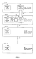
- the second-standard main apparatus 901-s includes a controller 903-s, a first base station interface 907-s-1 to a Mth base station interface 907-s-M, an empty slot 909-s and a backboard 911-s.
- the backboard 911-s is used for connecting the controller 903-s, the first base station interface 907-s-1 to the Mth base station interface 907-s-M and the empty slot 909-s mutually.
- the controller 903-s and the first base station interface 907-s-1 to the Mth base station interface 907-s-M have forms of card base plates inserted into slots of the backboard 911-s.
- a slot into which the card base plate is not inserted is the empty slot 909-s.
- the first base station interface 907-s-1 to the Mth base station interface 907-s-M are connected to a first base station 913-s-1 to a Mth base station 913-s-M respectively.
- a first terminal 921-1 to a Lth terminal 921-L perform radio communication with any base station among the first base station 913-s-1 to the Mth base station 913-s-M according to a predetermined communication standard.
- the predetermined standard is, for example, PHS (Personal Handy-phone System), Wireless LAN (Local Area Network) standard, W-CDMA (Wideband-Code Division Multiple Access), or MIMO (Multiple Input Multiple Output).
- the backboard 911-s relays data sent and received between the terminal 921 connected to any base station 913 included in the main apparatus system and the terminal 921' connected to any base station 913' included in the main apparatus system. This relay is performed by multiplexing the data with other data between other terminals and further demultiplexing them.
- PTL 1 discloses an art that a switching equipment is connected to a computer which functions as a server device wherein the switching equipment does not include a time switch function and a switching control function which are included in a normal switching equipment, and a time switcher and a CPU included in the server device act for the time switch function and the switching control function.
- the second-standard main apparatuses 901-1, 901-2, ...and 901-N are connected to each other via cables 905 and the controller 903-1 included in the first second-standard main apparatus 910-1 controls the second-standard main apparatuses 901-1, 901-2, ...and 901-N, because all of these main apparatuses comply with the second standard which is the same standard.
- a user considers about introduction of a first-standard function.
- the user if it is necessary to replace whole of the main apparatus system, the user hesitates about the introduction in terms of both of introduction cost and introduction work. Therefore, if it is possible that a main apparatus system configured by using the second-standard main apparatuses which has been previously used as is and adding one first-standard main apparatus includes the first-standard function, the introduction has merits in terms of both of introduction cost and introduction work, and the user does not hesitate about the introduction. Also, in terms of social economy and environment, the introduction has merits.
- the server device includes the time switch function and the switching control function which should be primarily included in the switching device, both of the switching device and the server device operate according to a common standard. Therefore, transform processing between different standards is impossible and therefore, it is impossible to connect the first-standard device and the second-standard device.
- the object of the present invention is to provide an inter-main-apparatus interface device wherein, even if the first-standard main apparatus and the second-standard main apparatus are gathered together in the main apparatus system, both of main apparatuses operate normally, a main-apparatus system including the inter-main-apparatus interface device, and an inter-main-apparatus interface method performed by the inter-main-apparatus interface device.
- an inter-main-apparatus interface device comprising: a control data interface provided between a first-standard main apparatus and a second-standard main apparatus for operating a controller included in the second-standard main apparatus on the basis of control data supplied from the first-standard main apparatus; and a content data interface provided between the first-standard main apparatus and the second-standard main apparatus for enabling the second-standard main apparatus, as controlled by the controller operating on the basis of the control data, to relay, by multiplexing and demultiplexing, content data sent and received by a base station connected to the first-standard main apparatus and content data sent and received by a base station connected to the second-standard main apparatus.
- an inter-main-apparatus interface method comprising the steps of: that a controller included in a second-standard main apparatus is operated on the basis of control data supplied from a first-standard main apparatus using a control data interface provided between the first-standard main apparatus and the second-standard main apparatus; and that the second-standard main apparatus, as controlled by the controller being operated on the basis of the control data, relays, by multiplexing and demultiplexing, content data sent and received by a base station connected to the first-standard main apparatus and content data sent and received by a base station connected to the second-standard main apparatus using a content data interface provided between the first-standard main apparatus and the second-standard main apparatus.
- an inter-main-apparatus interface program for causing a computer to function as an inter-main-apparatus interface, the program causing the computer to function as: a control data interface provided between a first-standard main apparatus and a second-standard main apparatus for operating a controller included in the second-standard main apparatus on the basis of control data supplied from the first-standard main apparatus; and a content data interface provided between the first-standard main apparatus and the second-standard main apparatus for enabling the second-standard main apparatus, as controlled by the controller operating on the basis of the control data, to relay, by multiplexing and demultiplexing, content data sent and received by a base station connected to the first-standard main apparatus and content data sent and received by a base station connected to the second-standard main apparatus.
- both of the first-standard main apparatuses and the second-standard main apparatuses operate normally even if both of those main apparatuses are gathered together in the main apparatus system.
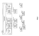
- Fig.3 is a conceptual diagram which illustrates an outline of whole of main apparatus system according to an embodiment of the present invention.
- a main apparatus system includes a first-standard main apparatus 101, a first second-standard main apparatus 901-1, a second second-standard main apparatus 901-2, ..., a Nth second-standard main apparatus 901-N.
- the first second-standard main apparatus 901-1, the second second-standard main apparatus 901-2, ... , and the Nth second-standard main apparatus 901-N are connected to each other via cables 905 just like an ordinary art. Contrary to this, the first-standard main apparatus 101 and the first second-standard main apparatus 901-1 are connected to each other via a cable 111 according to the present invention.
- the first-standard main apparatus 101 includes a controller 103 and an interface 105 for extension. Other components are described later.
- the controller 103 complies with the first-standard.
- the interface 105 for extension is used for connecting the first-standard main apparatus 101 and the first second-standard main apparatus 901-1.
- the controller 903-1 is similar to normal controllers 903-1 illustrated in Figs.1 and 2 , only hardware is validated.
- a firmware (not-illustrated) in the controller 903-1 which is validated on the basis of ordinary art is used for operating the hardware in the controller 903-1 according to the first-standard.
- the firmware in the controller 903-1 is written in, for example, ROM (Read Only Memory), and a firmware child card including this ROM is connected to the hardware in the controller 903-1 via a PCI bus (Peripheral Components Interconnect bus).
- PCI bus Peripheral Components Interconnect bus
- the firmware child card of the controller 903-1 is removed from the controller 903-1, and instead of this, a first connection card 107 is connected to the hardware of the controller 903-1 via the PCI bus. Therefore, the hardware of the controller 903-1 operates according to data supplied from and to the first connection card 107.
- the first connection card 107 is mounted on the controller 903-1, for example, as a child card of the controller 903-1. Details of the first connection card 107 are described later.
- a second connection card 109 is inserted into an empty slot 909-2 (refer to Fig.2 ) of the first second-standard main apparatus 901-1.
- the first connection card 107 and the second connection card 109 are connected to each other via a cable 113.
- the second connection card 109 and the interface 105 for extension are connected to each other via the cable 111. Details of the second connection card 109 are described later.
- the first-standard main apparatus 101 is controlled by the controller 103 included therein. Further, the controller 903-1 of the first second-standard main apparatus 901-1 operates according to data supplied from and to the first connection card 107 as noted above. Among the data, especially control data supplied from the first connection card 107 to the hardware of the controller 903-1 is supplied from the first-standard main apparatus 101 to the first connection card 107 via the interface 105 for extension, the cable 111, the second connection card 109 and the cable 113. Therefore, the hardware of the controller 903-1 of the first second-standard main apparatus 901-1 operates according to the control data supplied from the first-standard main apparatus 101.
- controller 903-2 of the second second-standard main apparatus 901-2 to a controller 903-N of the Nth second-standard main apparatus 901-N are invalidated, and the first second-standard main apparatus 901-1 to the Nth second-standard main apparatus 901-N are controlled by the controller 903-1 (directly by the hardware of the controller 903-1) included in the first second-standard main apparatus 901-1.
- the first second-standard main apparatus 910-1 to the Nth second-standard main apparatus 901-N operate according to the control data supplied from the first-standard main apparatus 101.
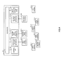
- Fig.4 is a conceptual diagram illustrating an inner configuration of the first-standard main apparatus 101 according to the embodiment of the present invention.
- the first-standard main apparatus 101 includes the controller 103, a first base station interface 121-1 to a Mth base station interface 121-M, the interface 105 for extension, and a backboard 111.
- the backboard 111 is used for connecting the controller 103, the first base station interface 121-1 to the Mth base station interface 121-M and the interface 105 for extension mutually.
- the controller 103, the first base station interface 121-1 to the Mth base station interface 121-M, and the interface 105 for extension have forms of card base plates inserted into slots of the backboard 111.
- the first base station interface 121-1 to the Mth base station interface 121-M are connected to a first base station 131-1 to a Mth base station 131-M respectively.
- a first terminal 141-1 to a Lth terminal 141-L perform radio communication with any base station among the first base station 131-1 to the Mth base station 131-M according to a predetermined communication standard.
- the predetermined standard is, for example, PHS (Personal Handy-phone System), Wireless LAN (Local Area Network) standard, W-CDMA (Wideband-Code Division Multiple Access), or MIMO (Multiple Input Multiple Output).
- each of the backboard 111 and the backboard 911-s relays data sent and received between the terminal 141 connected to any base station 131 or the terminal 921 connected to any base station 913 included in the main apparatus system, and the terminal 141' connected to any base station 131' or the terminal 921' connected to any base station 913' included in the main apparatus system.
- This relay is performed by multiplexing this data and data between other terminals and further demultiplexing them.
- Fig.5 is a block diagram illustrating details of an inner configuration of the first connection card 107 and details of an inner configuration of the second connection card 109.
- the first connection card 107 includes a first control data frame format converter 131 and a second control data frame format converter 133.
- the second connection card 109 includes a demultiplexer 121, a first content data frame format converter 123, a phase synchronization looper 125, a multiplexer 127 and a second content data frame format converter 129.
- the content data includes at least part of sound data, movie data, still image data, text data, electronic document data and so forth.
- the content data may be another type of content data.
- the demultiplexer 121 receives supplied multiplexing data 201 that the first control data, the first content data and a clock signal are multiplexed from the interface 105 for extension via the cable 111, performs a demultipexing process to the multiplexing data, and separately supplies the first control data 205, the first content data 203 and the clock signal 207 which are separated by the process.
- first included in “the first control data” and “first” included in “the first content data” indicate a transmission along a direction from the first-standard main apparatus 101 to the first second-standard main apparatus 901-1.
- terms of "a second control data” and "a second content data” are used.
- “Second” included in these terms indicate a transmission along a direction from the first second-standard main apparatus 901-1 to the first-standard main apparatus 101.
- the first control data and the first content data are frame-processed according to a frame format of the first-standard main apparatus, and even after demultiplexing, the first control data and the first content data are frame-processed according to the frame format of the first-standard main apparatus.
- the phase synchronization looper 125 receives the clock signal 207 from the demultiplexer 121. Further, the phase synchronization looper 125 synchronizes with the supplied clock signal and supplies a stable clock signal as a supplied clock signal 213. In each portion of the second connector card 109 and each portion of the first connector card 107, the supplied clock signal 213 is used as a clock signal therein. Further, the supplied clock signal is distributed to whole of the main apparatus system via the backboard 911-1 and used as a system clock signal in the whole of the main apparatus system.
- the first content data frame format converter 123 receives the first content data 203 from the demultiplexer 121 and converts a first content data frame format from the frame format of the first-standard main apparatus 101 to the frame format of the second-standard main apparatus 901.
- a buffer memory is included in the first content data frame format converter 123 inside.
- both of a frame timing signal according to the frame format of the first-standard main apparatus 101 and a frame timing signal according to the frame format of the second-standard main apparatus 901 are used.
- the first content data 209 including the frame format of the second-standard main apparatus 901 is supplied from the first content data frame format converter 123 to the backboard 911-1 of the second-standard main apparatus 901-1, and multiplexed and demultiplexed with other content data there, and thereby being relayed.
- the first control data format converter 131 receives the first control data 205 from the demultiplexer 121 via the cable 113, and converts the format of the first control data from the frame format of the first-standard main apparatus 101 to a format complying with a specification of a PCI bus 903P-1 which is an interface between a hardware and a firmware in the controller 903-1 of the second-standard main apparatus 901.
- a buffer memory is included in the first control data format converter 131 inside.
- both of a frame timing signal complying with the frame format of the first-standard main apparatus 101 and various control signals in the PCI bus are used.
- the first control data 211 complying with the specification of the PCI bus is supplied to a hardware 903H-1 of the controller 903-1 via the PCI bus 903P-1.
- a second content data 221 which is content data including a frame format of the second-standard main apparatus 901 and should be supplied from the first second-standard main apparatus 901-1 to the first-standard main apparatus 101 is multiplexed and demultiplexed with other content data in the backboard 911-1, and then, is supplied from the backboard 911-1 to the second content data frame format converter 129.
- the second content data frame format converter 129 converts the frame format of the second content data from the frame format of the second-standard main apparatus 901 to the frame format of the first-standard main apparatus 101.
- a buffer memory is included in the second content data frame format converter 129 inside.
- both of a frame timing signal pursuant to the frame format of the first-standard main apparatus 101 and a frame timing signal pursuant to the frame format of the second-standard main apparatus 901 are used.
- the second control data format converter 133 receives the second control data 223 from the hardware 903H-1 of the controller 903-1 via the PCI bus 903P-1, and converts the format of the second control data 223 from the format complying with the PCI bus 903P-1 which is the interface between the hardware 903H-1 and the firmware in the controller 903-1 of the second-standard main apparatus 901 to the frame format of the first-standard main apparatus 101.
- a buffer memory is included in the second control data format converter 133 inside.
- both of the frame timing signal pursuant to the frame format of the first-standard main apparatus and various control signals in the PCI bus are used.
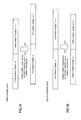
- the timing diagrams as shown in Figs. 6A, 6B , 7A and 7B are schematic for the explanation.
- the content data and/or control data may be continuous or discontinuous before and/or after the conversion.
- valid data may be included only at the timing when a supplying destination after the conversion can receive.
- data after the conversion may be discontinuous.
- the first content data does not lose an information which the first content data themselves have even after the format is converted in the first content data frame format converter 123.
- the second content data does not lose an information which the second content data themselves have even after the format is converted in the second content data frame format converter 129.
- the first control data does not lose an information which the first control data themselves have even after the format is converted in the first control data frame format converter 131. Therefore, the hardware 903H of the controller 903 of the first second-standard main apparatus 901-1 can operate under the initiative of the first-standard main apparatus 101.
- the second control data does not lose an information which the second control data themselves have even after the format is converted in the second control data frame format converter 133.
- the multiplexer 127 receives the second content data from the second content data frame format converter 129, receives the second control data from the second control data format converter 133, multiplexes these received data, and supplies the acquired multiplexing data 231 to the interface 105 for extension via the cable 111.
- the multiplexing data 231 are pursuant to the frame format of the first-standard main apparatus 101, the second content data included in this multiplexing data 231 are multiplexed and demultiplexed with other content data in the backboard 111 of the first-standard main apparatus 101 without further frame format conversion. Also, the second control data included in the multiplexing data 231 are multiplexed and demultiplexed with other control data in the backboard 111 of the first-standard main apparatus 101 without further frame format conversion.
- Above-described first control data includes main control data for controlling an operation of the hardware 903H-1 of the controller 903-1 of the first second-standard main apparatus 901-1.
- the hardware 903H-1 controlled by this main control data performs, for example, timing control for multiplexing and demultiplexing of the content data in the backboard 911-1.
- first control data are call control data for establishing a call between terminals, and include first direction call control data as call control data which are transmitted along a direction from the first-standard main apparatus 101 to the first second-standard main apparatus 901-1.
- above-described second control data are data relating to main control data which control operations of the hardware 903H-1 of the controller 903-1 of the first second-standard main apparatus 901-1, and include data which are transmitted along a direction from the second-standard main apparatus 901-1 to the first first-standard main apparatus 101.
- second control data are call control data for establishing a call between terminals, and include second direction call control data which are call control data transmitted along a direction from the second-standard main apparatus 901-1 to the first first-standard main apparatus 101.
- First effect brought by the present embodiments is a fact that the same function as the first-standard main apparatus is provided for the second-standard main apparatus. Also, it is possible that the second-standard main apparatus after system extension inherits functions of the second-standard main apparatus before the system extension. This is because the second-standard main apparatus becomes an extension shelf from a standpoint of the first-standard main apparatus.
- Second effect brought by the present embodiment is a fact that a system termination time because of wiring work, apparatus setting and so forth is short. This is because a new main apparatus system can be constructed merely by mounting additionally the first-standard main apparatus on a rack where the first to the Nth second-standard main apparatuses are mounted, exchanging the firmware of the controller of the first first-standard main apparatus into the first connection card, inserting the second connection card into the empty slot of the first first-standard main apparatus, and connecting predetermined cables.
- each of above-described first connection card, second connection card and interface for extension may be achieved by hardware, software, or combination thereof.
- the inter-main apparatus connection method executed by the above-described first connection card, second connection card and interface for extension may be achieved by hardware, software, or combination thereof.
- the expression "achieved by software” means “achieved by a computer reading and executing a program”.
- a program may be stored using various types of a non-transitory computer readable medium and may be supplied to the computer.
- the non-transitory computer readable medium includes various types of a tangible storage medium. Examples of the non-transitory computer readable medium include a magnetic recording medium (e.g., flexible disk, magnetic tape, hard disk drive), a magnet-optical recording medium (e.g., magneto-optical disk), a CD-ROM (Read Only Memory), a CD-R, a CD-R/W, a semiconductor memory (e.g., mask ROM, a PROM (Programmable ROM), an EPROM (Erasable PROM), a flash ROM, and a RAM (random access memory)).
- a magnetic recording medium e.g., flexible disk, magnetic tape, hard disk drive
- a magnet-optical recording medium e.g., magneto-optical disk
- CD-ROM Read Only Memory
- CD-R Read Only Memory
- CD-R/W a semiconductor memory
- the program may be supplied to the computer by various types of a transitory computer readable medium as well.
- Examples of the transitory computer readable medium include an electric signal, an optical signal, and an electromagnetic wave.
- the transitory computer readable medium may supply the program to the computer via a wired channel such as an electric cable or an optical fiber, or via a wireless channel.
- An inter-main-apparatus interface device comprising:
- control data includes main control data for enabling the second-standard main apparatus, as controlled by the controller operating on the basis of the control data, to relay, by multiplexing and demultiplexindg, content data sent and received by the base station connected to the first-standard main apparatus and content data sent and received by the base station connected to the second-standard main apparatus.
- control data includes a first direction call control data supplied from the first-standard main apparatus to the second-standard main apparatus among call control data for controlling a call between a terminal connected to the base station connected to the first-standard main apparatus and a terminal connected to the base station connected to the second-standard main apparatus or a terminal connected to a base station connected to another second-standard main apparatus connected to the second-standard main apparatus.
- control data interface comprises a first converter configured to convert the control data supplied from the first-standard main apparatus to make the control data be pursuant to a specification of an interface included in the controller, and the control data becoming pursuant to the specification of the interface by the first converter is supplied to the controller via the interface.
- the inter-main-apparatus interface device according to any one of Supplementary notes 1 to 4, wherein a second direction call control data supplied from the second-standard main apparatus to the first-standard main apparatus among call control data for controlling a call between the terminal connected to the base station connected to the first-standard main apparatus and the terminal connected to the base station connected to the second-standard main apparatus or the terminal as connected to the base station connected to another second-standard main apparatus connected to the second-standard main apparatus is output from the interface included in the controller according to the specification of the interface, and the control data interface comprises a second converter configured to convert the second direction call control data supplied from the interface included in the controller according to the specification of the interface to make the second direction call control data be pursuant to a specification of the first-standard main apparatus.
- the inter-main-apparatus interface device according to any one of Supplementary notes 1 to 5, wherein the content data interface comprises:
- inter-main-apparatus interface device according to any one of Supplementary notes 1 to 6, further comprising:
- inter-main-apparatus interface device according to any one of Supplementary notes 1 to 7, wherein the control data and the content data supplied from the first-standard main apparatus to the second-standard main apparatus are multiplexed, the inter-main-apparatus interface device further comprises a demultiplexer configured to demultiplex the multiplexed control data and content data.
- inter-main-apparatus interface device according to any one of Supplementary notes 1 to 7, further comprising:
- a main-apparatus system comprising the inter-main-apparatus interface device according to any one of claims 1 to 9, the first-standard main apparatus and the second-standard main apparatus.
- An inter-main-apparatus interface method comprising the steps of:
- control data includes main control data for enabling the second-standard main apparatus, as controlled by the controller operating on the basis of the control data, to relay, by multiplexing and demultiplexindg, content data sent and received by the base station connected to the first-standard main apparatus and content data sent and received by the base station connected to the second-standard main apparatus.
- control data includes a first direction call control data supplied from the first-standard main apparatus to the second-standard main apparatus among call control data for controlling a call between a terminal connected to the base station connected to the first-standard main apparatus and a terminal connected to the base station connected to the second-standard main apparatus or a terminal connected to a base station connected to another second-standard main apparatus connected to the second-standard main apparatus.
- the inter-main-apparatus interface method according to any one of Supplementary notes 12 to 15, wherein a second direction call control data supplied from the second-standard main apparatus to the first-standard main apparatus among call control data for controlling a call between the terminal connected to the base station connected to the first-standard main apparatus and the terminal connected to the base station connected to the second-standard main apparatus or the terminal as connected to the base station connected to another second-standard main apparatus connected to the second-standard main apparatus is output from the interface included in the controller according to the specification of the interface, and the control data interface comprises a second converter configured to convert the second direction call control data supplied from the interface included in the controller according to the specification of the interface to make the second direction call control data be pursuant to a specification of the first-standard main apparatus.
- An inter-main-apparatus interface program for causing a computer to function as an inter-main-apparatus interface, the program causing the computer to function as:
- control data includes main control data for enabling the second-standard main apparatus, as controlled by the controller operating on the basis of the control data, to relay, by multiplexing and demultiplexindg, content data sent and received by the base station connected to the first-standard main apparatus and content data sent and received by the base station connected to the second-standard main apparatus.
- control data includes a first direction call control data supplied from the first-standard main apparatus to the second-standard main apparatus among call control data for controlling a call between a terminal connected to the base station connected to the first-standard main apparatus and a terminal connected to the base station connected to the second-standard main apparatus or a terminal connected to a base station connected to another second-standard main apparatus connected to the second-standard main apparatus.
- control data interface comprises a first converter configured to convert the control data supplied from the first-standard main apparatus to make the control data be pursuant to a specification of an interface included in the controller, and the control data becoming pursuant to the specification of the interface by the first converter is supplied to the controller via the interface.
- the inter-main-apparatus interface program according to any one of Supplementary notes 21 to 24, wherein a second direction call control data supplied from the second-standard main apparatus to the first-standard main apparatus among call control data for controlling a call between the terminal connected to the base station connected to the first-standard main apparatus and the terminal connected to the base station connected to the second-standard main apparatus or the terminal as connected to the base station connected to another second-standard main apparatus connected to the second-standard main apparatus is output from the interface included in the controller according to the specification of the interface, and the control data interface comprises a second converter configured to convert the second direction call control data supplied from the interface included in the controller according to the specification of the interface to make the second direction call control data be pursuant to a specification of the first-standard main apparatus.
- the inter-main-apparatus interface program according to any one of Supplementary notes 21 to 26, the program further causing the computer to function as a clock interface for enabling the second-standard main apparatus to operate using a clock signal generated by the first-standard main apparatus.
- inter-main-apparatus interface program according to any one of Supplementary notes 21 to 27, wherein the control data and the content data as supplied from the first-standard main apparatus to the second-standard main apparatus are multiplexed, the program further causing the computer to function as a demultiplexer configured to demultiplex the multiplexed control data and content data.
- the inter-main-apparatus interface program according to any one of Supplementary notes 21 to 27, further causing the computer to function as a multiplexer configured to multiplex the control data and the content data which are to be supplied from the second-standard main apparatus to the first-standard main apparatus, wherein the control data and the content data multiplexed by the multiplexer are supplied to the first-standard main apparatus.
- the present invention can be utilized for connecting one-standard main apparatus to another-standard main apparatus.
Landscapes
- Engineering & Computer Science (AREA)
- Physics & Mathematics (AREA)
- General Physics & Mathematics (AREA)
- Computer Networks & Wireless Communication (AREA)
- Theoretical Computer Science (AREA)
- Signal Processing (AREA)
- General Engineering & Computer Science (AREA)
- Astronomy & Astrophysics (AREA)
- Automation & Control Theory (AREA)
- Mobile Radio Communication Systems (AREA)
- Sub-Exchange Stations And Push- Button Telephones (AREA)
- Telephonic Communication Services (AREA)
- Hardware Redundancy (AREA)
- Communication Control (AREA)
- Bus Control (AREA)
- Selective Calling Equipment (AREA)
- Small-Scale Networks (AREA)
Abstract
Description
- The present invention relates to an inter-main-apparatus interface device which connects a main apparatus and other main apparatuses, particularly to an inter-main-apparatus interface device which connects a first-standard main apparatus and second-standard main apparatuses. Further, the present invention relates to a main-apparatus system including the inter-main-apparatus device and an inter-main-apparatus interface method performed by the inter-main-apparatus interface device.
- A configuration of a normal main apparatus system is illustrated in
Fig.1 . Referring toFig.1 , the normal main apparatus system includes a plurality of main apparatuses 901-1, 901-2, ... and 901-N. Here, all of main apparatuses 901-1, 901-2, ... and 901-N comply with the same standard, and are assumed to comply with a second-standard. Therefore, the main apparatuses 901-1, 901-2, ... and 901-N are referred to as second-standard main apparatuses 901-1, 901-2, ...and 901-N. Each of the plurality of second-standard main apparatuses can function independently. In that case, all operations of the second-standardmain apparatus 901 are controlled by acontroller 903 included therein. By combining a plurality of the second-standard main apparatuses, it is possible to build out a main apparatus system. In this case, as illustrated inFig.1 , the plurality of second-standard main apparatuses 901-1, 901-2, ... and 901-N are connected to each other bycables 905. Further, only a controller 903-1 in one main apparatus 901 (a first second-standard main apparatus 901-1 in an example ofFig.1 ) is validated and other controllers (a controller 903-2 of a second second-standard controller 901-2 to a controller 903-N of a Nth second-standard controller 901-N) of othermain apparatuses 901 are invalidated. Further, the first second-standard main apparatus 901-1 to the Nth second-standard main apparatus 901-N are controlled by the controller 903-1 included in the first second-standard main apparatus 901-1. -
Fig.2 is a conceptual diagram which illustrates an inner structure and so forth of the second-standard main apparatus 901-s (s=1, 2, ..., N). Referring toFig.2 , the second-standard main apparatus 901-s includes a controller 903-s, a first base station interface 907-s-1 to a Mth base station interface 907-s-M, an empty slot 909-s and a backboard 911-s. The backboard 911-s is used for connecting the controller 903-s, the first base station interface 907-s-1 to the Mth base station interface 907-s-M and the empty slot 909-s mutually. The controller 903-s and the first base station interface 907-s-1 to the Mth base station interface 907-s-M have forms of card base plates inserted into slots of the backboard 911-s. A slot into which the card base plate is not inserted is the empty slot 909-s. - The first base station interface 907-s-1 to the Mth base station interface 907-s-M are connected to a first base station 913-s-1 to a Mth base station 913-s-M respectively.
- A first terminal 921-1 to a Lth terminal 921-L perform radio communication with any base station among the first base station 913-s-1 to the Mth base station 913-s-M according to a predetermined communication standard. The predetermined standard is, for example, PHS (Personal Handy-phone System), Wireless LAN (Local Area Network) standard, W-CDMA (Wideband-Code Division Multiple Access), or MIMO (Multiple Input Multiple Output).
- On the basis of above configuration, in the main apparatus system, one
terminal 921 connected to any base station 913-s-m (m=1, 2, ..., M) connected to any second-standard main apparatus 901-s (s=1, 2, ..., N) can communicate not only with anotherterminal 921 connected to any base station 913-s-m' (m'=1, 2, ..., M) connected to the main apparatus 901-s but also with theother terminal 921 connected to any base station 913-s'-m' (m'=1, 2, ..., M) connected to any other main apparatus 901-s' (s'=1, 2, ..., N). Therefore, the backboard 911-s relays data sent and received between theterminal 921 connected to anybase station 913 included in the main apparatus system and the terminal 921' connected to any base station 913' included in the main apparatus system. This relay is performed by multiplexing the data with other data between other terminals and further demultiplexing them. -
PTL 1 discloses an art that a switching equipment is connected to a computer which functions as a server device wherein the switching equipment does not include a time switch function and a switching control function which are included in a normal switching equipment, and a time switcher and a CPU included in the server device act for the time switch function and the switching control function. - {PTL 1} Japanese Patent Application Publication No.
2002-261924 - By the way, as illustrated in
Fig.1 , it is possible that the second-standard main apparatuses 901-1, 901-2, ...and 901-N are connected to each other viacables 905 and the controller 903-1 included in the first second-standard main apparatus 910-1 controls the second-standard main apparatuses 901-1, 901-2, ...and 901-N, because all of these main apparatuses comply with the second standard which is the same standard. - Therefore, even if a main apparatus which complies with a first-standard as different from the second-standard is connected to above main apparatus system merely via a cable and a controller in the main apparatus is invalidated, the main apparatus which complies with the first-standard cannot operate normally. Therefore, it is impossible to extend above main apparatus system easily.
- Also, even if the main apparatus which complies with the first-standard as different from the second standard is connected to above main apparatus system merely via a cable, the controller of the main apparatus is validated and the controllers of all second-standard main apparatuses are invalidated, neither of the main apparatus which complies with the first-standard and the main apparatuses which comply with the second-standard cannot operate normally. Therefore, it is impossible to extend above main apparatus system easily.
- Here, in a case where a currently-used main apparatus system is composed of a plurality of second-standard main apparatuses and a first-standard main apparatus which has higher function than the second-standard main apparatuses is developed by a manufacturer, a user considers about introduction of a first-standard function. However, if it is necessary to replace whole of the main apparatus system, the user hesitates about the introduction in terms of both of introduction cost and introduction work. Therefore, if it is possible that a main apparatus system configured by using the second-standard main apparatuses which has been previously used as is and adding one first-standard main apparatus includes the first-standard function, the introduction has merits in terms of both of introduction cost and introduction work, and the user does not hesitate about the introduction. Also, in terms of social economy and environment, the introduction has merits.
- In the art as disclosed in
PTL 1, although the server device includes the time switch function and the switching control function which should be primarily included in the switching device, both of the switching device and the server device operate according to a common standard. Therefore, transform processing between different standards is impossible and therefore, it is impossible to connect the first-standard device and the second-standard device. - Then, the object of the present invention is to provide an inter-main-apparatus interface device wherein, even if the first-standard main apparatus and the second-standard main apparatus are gathered together in the main apparatus system, both of main apparatuses operate normally, a main-apparatus system including the inter-main-apparatus interface device, and an inter-main-apparatus interface method performed by the inter-main-apparatus interface device.
- According to the present invention, there is provided an inter-main-apparatus interface device, comprising: a control data interface provided between a first-standard main apparatus and a second-standard main apparatus for operating a controller included in the second-standard main apparatus on the basis of control data supplied from the first-standard main apparatus; and a content data interface provided between the first-standard main apparatus and the second-standard main apparatus for enabling the second-standard main apparatus, as controlled by the controller operating on the basis of the control data, to relay, by multiplexing and demultiplexing, content data sent and received by a base station connected to the first-standard main apparatus and content data sent and received by a base station connected to the second-standard main apparatus.
- Further, according to the present invention, there is provided an inter-main-apparatus interface method, comprising the steps of: that a controller included in a second-standard main apparatus is operated on the basis of control data supplied from a first-standard main apparatus using a control data interface provided between the first-standard main apparatus and the second-standard main apparatus; and that the second-standard main apparatus, as controlled by the controller being operated on the basis of the control data, relays, by multiplexing and demultiplexing, content data sent and received by a base station connected to the first-standard main apparatus and content data sent and received by a base station connected to the second-standard main apparatus using a content data interface provided between the first-standard main apparatus and the second-standard main apparatus.
- Furthermore, according to the present invention, there is provided an inter-main-apparatus interface program for causing a computer to function as an inter-main-apparatus interface, the program causing the computer to function as: a control data interface provided between a first-standard main apparatus and a second-standard main apparatus for operating a controller included in the second-standard main apparatus on the basis of control data supplied from the first-standard main apparatus; and a content data interface provided between the first-standard main apparatus and the second-standard main apparatus for enabling the second-standard main apparatus, as controlled by the controller operating on the basis of the control data, to relay, by multiplexing and demultiplexing, content data sent and received by a base station connected to the first-standard main apparatus and content data sent and received by a base station connected to the second-standard main apparatus.
- According to the present invention, it is possible that both of the first-standard main apparatuses and the second-standard main apparatuses operate normally even if both of those main apparatuses are gathered together in the main apparatus system.
-
- {
FIG. 1 } A figure is a conceptual diagram illustrating a normal main apparatus system. - {
FIG. 2 } A figure is a conceptual diagram illustrating an inner configuration of the second-standard main apparatus as illustrated inFig.1 . - {
FIG. 3 } A figure is a conceptual diagram illustrating an outline of whole of the main apparatus system according to an embodiment of the present invention. - {
FIG. 4 } A figure is a conceptual diagram illustrating an inner configuration of the first-standardmain apparatus 101 according to an embodiment of the present invention. - {
FIG. 5 } A figure is a block diagram illustrating details about an inner configuration of afirst connection card 107 and details about an inner configuration of asecond connection card 109. - {
FIG. 6A } A figure is a conceptual diagram illustrating a conversion of first content data. - {
FIG. 6B } A figure is a conceptual diagram illustrating a conversion of second content data. - {
FIG.7A } A figure is a conceptual diagram illustrating a conversion of first control data. - {
FIG.7B }A figure is a conceptual diagram illustrating a conversion of second control data. - We explain about embodiments for implementing the present invention in detail by referring to figures.
-
Fig.3 is a conceptual diagram which illustrates an outline of whole of main apparatus system according to an embodiment of the present invention. - Referring to
Fig.3 , a main apparatus system according to the embodiment of the present invention includes a first-standardmain apparatus 101, a first second-standard main apparatus 901-1, a second second-standard main apparatus 901-2, ..., a Nth second-standard main apparatus 901-N. - The first second-standard main apparatus 901-1, the second second-standard main apparatus 901-2, ... , and the Nth second-standard main apparatus 901-N are connected to each other via
cables 905 just like an ordinary art. Contrary to this, the first-standardmain apparatus 101 and the first second-standard main apparatus 901-1 are connected to each other via acable 111 according to the present invention. - The first-standard
main apparatus 101 includes acontroller 103 and aninterface 105 for extension. Other components are described later. - The
controller 103 complies with the first-standard. Theinterface 105 for extension is used for connecting the first-standardmain apparatus 101 and the first second-standard main apparatus 901-1. - Seeing the first second-standard main apparatus 901-1 in
Fig.3 , although the controller 903-1 is similar to normal controllers 903-1 illustrated inFigs.1 and2 , only hardware is validated. A firmware (not-illustrated) in the controller 903-1 which is validated on the basis of ordinary art is used for operating the hardware in the controller 903-1 according to the first-standard. The firmware in the controller 903-1 is written in, for example, ROM (Read Only Memory), and a firmware child card including this ROM is connected to the hardware in the controller 903-1 via a PCI bus (Peripheral Components Interconnect bus). - In the present embodiment, the firmware child card of the controller 903-1 is removed from the controller 903-1, and instead of this, a
first connection card 107 is connected to the hardware of the controller 903-1 via the PCI bus. Therefore, the hardware of the controller 903-1 operates according to data supplied from and to thefirst connection card 107. Thefirst connection card 107 is mounted on the controller 903-1, for example, as a child card of the controller 903-1. Details of thefirst connection card 107 are described later. - A
second connection card 109 is inserted into an empty slot 909-2 (refer toFig.2 ) of the first second-standard main apparatus 901-1. Thefirst connection card 107 and thesecond connection card 109 are connected to each other via acable 113. Thesecond connection card 109 and theinterface 105 for extension are connected to each other via thecable 111. Details of thesecond connection card 109 are described later. - The first-standard
main apparatus 101 is controlled by thecontroller 103 included therein. Further, the controller 903-1 of the first second-standard main apparatus 901-1 operates according to data supplied from and to thefirst connection card 107 as noted above. Among the data, especially control data supplied from thefirst connection card 107 to the hardware of the controller 903-1 is supplied from the first-standardmain apparatus 101 to thefirst connection card 107 via theinterface 105 for extension, thecable 111, thesecond connection card 109 and thecable 113. Therefore, the hardware of the controller 903-1 of the first second-standard main apparatus 901-1 operates according to the control data supplied from the first-standardmain apparatus 101. - Further, all of a controller 903-2 of the second second-standard main apparatus 901-2 to a controller 903-N of the Nth second-standard main apparatus 901-N are invalidated, and the first second-standard main apparatus 901-1 to the Nth second-standard main apparatus 901-N are controlled by the controller 903-1 (directly by the hardware of the controller 903-1) included in the first second-standard main apparatus 901-1.
- Therefore, the first second-standard main apparatus 910-1 to the Nth second-standard main apparatus 901-N operate according to the control data supplied from the first-standard
main apparatus 101. - Therefore, whole of the main apparatus system including the first-standard
main apparatus 101 and the first second-standard main apparatus 901-1, the second second-standard main apparatus 901-2, ..., and the Nth second-standard main apparatus 901-N are controlled by thecontroller 103 included in the first-standardmain apparatus 101. -
Fig.4 is a conceptual diagram illustrating an inner configuration of the first-standardmain apparatus 101 according to the embodiment of the present invention. Referring toFig.4 , the first-standardmain apparatus 101 includes thecontroller 103, a first base station interface 121-1 to a Mth base station interface 121-M, theinterface 105 for extension, and abackboard 111. Thebackboard 111 is used for connecting thecontroller 103, the first base station interface 121-1 to the Mth base station interface 121-M and theinterface 105 for extension mutually. Thecontroller 103, the first base station interface 121-1 to the Mth base station interface 121-M, and theinterface 105 for extension have forms of card base plates inserted into slots of thebackboard 111. - The first base station interface 121-1 to the Mth base station interface 121-M are connected to a first base station 131-1 to a Mth base station 131-M respectively.
- A first terminal 141-1 to a Lth terminal 141-L perform radio communication with any base station among the first base station 131-1 to the Mth base station 131-M according to a predetermined communication standard. The predetermined standard is, for example, PHS (Personal Handy-phone System), Wireless LAN (Local Area Network) standard, W-CDMA (Wideband-Code Division Multiple Access), or MIMO (Multiple Input Multiple Output).
- On the basis of above configuration, in the main apparatus system, one
terminal 141 connected to any base station 131 -m (m=1, 2, ..., M) connected to the first-standardmain apparatus 101 can communicate not only with another terminal 141 connected to any base station 131-m' (m'=1, 2, ..., M) connected to the first-standardmain apparatus 101 but also with theother terminal 921 connected to any base station 913-s-m (m=1, 2, ..., M) connected to any second-standard main apparatus 901-s (s=1, 2, ..., N). Furthermore, just like a case of ordinary art, in the main apparatus system, oneterminal 921 connected to any base station 913-s-m (m=1, 2, ..., M) connected to any second-standard main apparatus 901-s (s=1,2, ..., N) can communicate with another terminal 921 connected to any base station 913-s'-m' (m'=1,2, ..., M) connected to any other main apparatus 901-s' (s'=1, 2, ..., N). - Therefore, each of the
backboard 111 and the backboard 911-s relays data sent and received between the terminal 141 connected to anybase station 131 or the terminal 921 connected to anybase station 913 included in the main apparatus system, and the terminal 141' connected to any base station 131' or the terminal 921' connected to any base station 913' included in the main apparatus system. This relay is performed by multiplexing this data and data between other terminals and further demultiplexing them. -
Fig.5 is a block diagram illustrating details of an inner configuration of thefirst connection card 107 and details of an inner configuration of thesecond connection card 109. - Referring to
Fig. 5 , thefirst connection card 107 includes a first control dataframe format converter 131 and a second control dataframe format converter 133. Further, thesecond connection card 109 includes ademultiplexer 121, a first content dataframe format converter 123, aphase synchronization looper 125, amultiplexer 127 and a second content data frame format converter 129. Here, the content data includes at least part of sound data, movie data, still image data, text data, electronic document data and so forth. However, the content data may be another type of content data. - The
demultiplexer 121 receives supplied multiplexing data 201 that the first control data, the first content data and a clock signal are multiplexed from theinterface 105 for extension via thecable 111, performs a demultipexing process to the multiplexing data, and separately supplies thefirst control data 205, thefirst content data 203 and theclock signal 207 which are separated by the process. Here, "first" included in "the first control data" and "first" included in "the first content data" indicate a transmission along a direction from the first-standardmain apparatus 101 to the first second-standard main apparatus 901-1. In a later explanation, terms of "a second control data" and "a second content data" are used. "Second" included in these terms indicate a transmission along a direction from the first second-standard main apparatus 901-1 to the first-standardmain apparatus 101. In the multiplexing data, the first control data and the first content data are frame-processed according to a frame format of the first-standard main apparatus, and even after demultiplexing, the first control data and the first content data are frame-processed according to the frame format of the first-standard main apparatus. - The
phase synchronization looper 125 receives theclock signal 207 from thedemultiplexer 121. Further, thephase synchronization looper 125 synchronizes with the supplied clock signal and supplies a stable clock signal as a suppliedclock signal 213. In each portion of thesecond connector card 109 and each portion of thefirst connector card 107, the suppliedclock signal 213 is used as a clock signal therein. Further, the supplied clock signal is distributed to whole of the main apparatus system via the backboard 911-1 and used as a system clock signal in the whole of the main apparatus system. - As illustrated in a timing diagram as
Fig.6A , the first content dataframe format converter 123 receives thefirst content data 203 from thedemultiplexer 121 and converts a first content data frame format from the frame format of the first-standardmain apparatus 101 to the frame format of the second-standardmain apparatus 901. For the conversion of the frame format, for example, a buffer memory is included in the first content dataframe format converter 123 inside. Further, for the conversion of the frame format, for example, both of a frame timing signal according to the frame format of the first-standardmain apparatus 101 and a frame timing signal according to the frame format of the second-standardmain apparatus 901 are used. Thefirst content data 209 including the frame format of the second-standardmain apparatus 901 is supplied from the first content dataframe format converter 123 to the backboard 911-1 of the second-standard main apparatus 901-1, and multiplexed and demultiplexed with other content data there, and thereby being relayed. - As illustrated in a timing diagram as
Fig.7A , the first controldata format converter 131 receives thefirst control data 205 from thedemultiplexer 121 via thecable 113, and converts the format of the first control data from the frame format of the first-standardmain apparatus 101 to a format complying with a specification of aPCI bus 903P-1 which is an interface between a hardware and a firmware in the controller 903-1 of the second-standardmain apparatus 901. For the conversion of the format, for example, a buffer memory is included in the first controldata format converter 131 inside. Further, for the conversion of the format, for example, both of a frame timing signal complying with the frame format of the first-standardmain apparatus 101 and various control signals in the PCI bus are used. Thefirst control data 211 complying with the specification of the PCI bus is supplied to ahardware 903H-1 of the controller 903-1 via thePCI bus 903P-1. - A
second content data 221 which is content data including a frame format of the second-standardmain apparatus 901 and should be supplied from the first second-standard main apparatus 901-1 to the first-standardmain apparatus 101 is multiplexed and demultiplexed with other content data in the backboard 911-1, and then, is supplied from the backboard 911-1 to the second content data frame format converter 129. - As illustrated in a timing diagram as
Fig.6B , the second content data frame format converter 129 converts the frame format of the second content data from the frame format of the second-standardmain apparatus 901 to the frame format of the first-standardmain apparatus 101. For the conversion of the frame format, for example, a buffer memory is included in the second content data frame format converter 129 inside. Further, for the conversion of the frame format, for example, both of a frame timing signal pursuant to the frame format of the first-standardmain apparatus 101 and a frame timing signal pursuant to the frame format of the second-standardmain apparatus 901 are used. - As illustrated in a timing diagram of
Fig.7B , the second controldata format converter 133 receives thesecond control data 223 from thehardware 903H-1 of the controller 903-1 via thePCI bus 903P-1, and converts the format of thesecond control data 223 from the format complying with thePCI bus 903P-1 which is the interface between thehardware 903H-1 and the firmware in the controller 903-1 of the second-standardmain apparatus 901 to the frame format of the first-standardmain apparatus 101. Further, for the conversion of the format, for example, a buffer memory is included in the second controldata format converter 133 inside. Further, for the conversion of the format, for example, both of the frame timing signal pursuant to the frame format of the first-standard main apparatus and various control signals in the PCI bus are used. - Here, the timing diagrams as shown in
Figs. 6A, 6B ,7A and 7B , are schematic for the explanation. In fact, the content data and/or control data may be continuous or discontinuous before and/or after the conversion. For example, valid data may be included only at the timing when a supplying destination after the conversion can receive. To that end, for example, data after the conversion may be discontinuous. - Further, the first content data does not lose an information which the first content data themselves have even after the format is converted in the first content data
frame format converter 123. Similarly, the second content data does not lose an information which the second content data themselves have even after the format is converted in the second content data frame format converter 129. Similarly, the first control data does not lose an information which the first control data themselves have even after the format is converted in the first control dataframe format converter 131. Therefore, thehardware 903H of thecontroller 903 of the first second-standard main apparatus 901-1 can operate under the initiative of the first-standardmain apparatus 101. Similarly, the second control data does not lose an information which the second control data themselves have even after the format is converted in the second control dataframe format converter 133. - The
multiplexer 127 receives the second content data from the second content data frame format converter 129, receives the second control data from the second controldata format converter 133, multiplexes these received data, and supplies the acquired multiplexingdata 231 to theinterface 105 for extension via thecable 111. - Because the multiplexing
data 231 are pursuant to the frame format of the first-standardmain apparatus 101, the second content data included in thismultiplexing data 231 are multiplexed and demultiplexed with other content data in thebackboard 111 of the first-standardmain apparatus 101 without further frame format conversion. Also, the second control data included in the multiplexingdata 231 are multiplexed and demultiplexed with other control data in thebackboard 111 of the first-standardmain apparatus 101 without further frame format conversion. - Above-described first control data includes main control data for controlling an operation of the
hardware 903H-1 of the controller 903-1 of the first second-standard main apparatus 901-1. Thehardware 903H-1 controlled by this main control data performs, for example, timing control for multiplexing and demultiplexing of the content data in the backboard 911-1. - Further, above-described first control data are call control data for establishing a call between terminals, and include first direction call control data as call control data which are transmitted along a direction from the first-standard
main apparatus 101 to the first second-standard main apparatus 901-1. - Further, above-described second control data are data relating to main control data which control operations of the
hardware 903H-1 of the controller 903-1 of the first second-standard main apparatus 901-1, and include data which are transmitted along a direction from the second-standard main apparatus 901-1 to the first first-standardmain apparatus 101. - Further, above-described second control data are call control data for establishing a call between terminals, and include second direction call control data which are call control data transmitted along a direction from the second-standard main apparatus 901-1 to the first first-standard
main apparatus 101. - First effect brought by the present embodiments is a fact that the same function as the first-standard main apparatus is provided for the second-standard main apparatus. Also, it is possible that the second-standard main apparatus after system extension inherits functions of the second-standard main apparatus before the system extension. This is because the second-standard main apparatus becomes an extension shelf from a standpoint of the first-standard main apparatus.
- Second effect brought by the present embodiment is a fact that a system termination time because of wiring work, apparatus setting and so forth is short. This is because a new main apparatus system can be constructed merely by mounting additionally the first-standard main apparatus on a rack where the first to the Nth second-standard main apparatuses are mounted, exchanging the firmware of the controller of the first first-standard main apparatus into the first connection card, inserting the second connection card into the empty slot of the first first-standard main apparatus, and connecting predetermined cables.
- Meanwhile, each of above-described first connection card, second connection card and interface for extension may be achieved by hardware, software, or combination thereof. Further, the inter-main apparatus connection method executed by the above-described first connection card, second connection card and interface for extension may be achieved by hardware, software, or combination thereof. Here, the expression "achieved by software" means "achieved by a computer reading and executing a program".
- A program may be stored using various types of a non-transitory computer readable medium and may be supplied to the computer. The non-transitory computer readable medium includes various types of a tangible storage medium. Examples of the non-transitory computer readable medium include a magnetic recording medium (e.g., flexible disk, magnetic tape, hard disk drive), a magnet-optical recording medium (e.g., magneto-optical disk), a CD-ROM (Read Only Memory), a CD-R, a CD-R/W, a semiconductor memory (e.g., mask ROM, a PROM (Programmable ROM), an EPROM (Erasable PROM), a flash ROM, and a RAM (random access memory)). Further, the program may be supplied to the computer by various types of a transitory computer readable medium as well. Examples of the transitory computer readable medium include an electric signal, an optical signal, and an electromagnetic wave. The transitory computer readable medium may supply the program to the computer via a wired channel such as an electric cable or an optical fiber, or via a wireless channel.
- A part or entirety of the above-described embodiments may be described as in the following supplementary notes, but are not limited thereto.
- An inter-main-apparatus interface device, comprising:
- a control data interface provided between a first-standard main apparatus and a second-standard main apparatus for operating a controller included in the second-standard main apparatus on the basis of control data supplied from the first-standard main apparatus; and
- a content data interface provided between the first-standard main apparatus and the second-standard main apparatus for enabling the second-standard main apparatus, as controlled by the controller operating on the basis of the control data, to relay, by multiplexing and demultiplexing, content data sent and received by a base station connected to the first-standard main apparatus and content data sent and received by a base station connected to the second-standard main apparatus.
- The inter-main-apparatus interface device according to
Supplementary note 1, wherein
the control data includes main control data for enabling the second-standard main apparatus, as controlled by the controller operating on the basis of the control data, to relay, by multiplexing and demultiplexindg, content data sent and received by the base station connected to the first-standard main apparatus and content data sent and received by the base station connected to the second-standard main apparatus. - The inter-main-apparatus interface device according to
Supplementary note
the control data includes a first direction call control data supplied from the first-standard main apparatus to the second-standard main apparatus among call control data for controlling a call between a terminal connected to the base station connected to the first-standard main apparatus and a terminal connected to the base station connected to the second-standard main apparatus or a terminal connected to a base station connected to another second-standard main apparatus connected to the second-standard main apparatus. - The inter-main-apparatus interface device according to any one of
Supplementary notes 1 to 3, wherein
the control data interface comprises a first converter configured to convert the control data supplied from the first-standard main apparatus to make the control data be pursuant to a specification of an interface included in the controller, and
the control data becoming pursuant to the specification of the interface by the first converter is supplied to the controller via the interface. - The inter-main-apparatus interface device according to any one of
Supplementary notes 1 to 4, wherein
a second direction call control data supplied from the second-standard main apparatus to the first-standard main apparatus among call control data for controlling a call between the terminal connected to the base station connected to the first-standard main apparatus and the terminal connected to the base station connected to the second-standard main apparatus or the terminal as connected to the base station connected to another second-standard main apparatus connected to the second-standard main apparatus is output from the interface included in the controller according to the specification of the interface, and
the control data interface comprises a second converter configured to convert the second direction call control data supplied from the interface included in the controller according to the specification of the interface to make the second direction call control data be pursuant to a specification of the first-standard main apparatus. - The inter-main-apparatus interface device according to any one of
Supplementary notes 1 to 5, wherein
the content data interface comprises: - a first frame format converter configured to convert a frame format of content data supplied from the first-standard main apparatus from a frame format of the first-standard main apparatus to a frame format of the second-standard main apparatus; and
- a second frame format converter configured to receive content data that is demultiplexed in the second-standard main apparatus and to be supplied to the first-standard main apparatus and convert a frame format of the received content data from the frame format of the second-standard main apparatus to the frame format of the first-standard main apparatus,
- The inter-main-apparatus interface device according to any one of
Supplementary notes 1 to 6, further comprising: - a clock interface for enabling the second-standard main apparatus to operate using a clock signal generated by the first-standard main apparatus.
- The inter-main-apparatus interface device according to any one of
Supplementary notes 1 to 7, wherein
the control data and the content data supplied from the first-standard main apparatus to the second-standard main apparatus are multiplexed,
the inter-main-apparatus interface device further comprises a demultiplexer configured to demultiplex the multiplexed control data and content data. - The inter-main-apparatus interface device according to any one of
Supplementary notes 1 to 7, further comprising: - a multiplexer configured to multiplex the control data and the content data which are to be supplied from the second-standard main apparatus to the first-standard main apparatus, wherein
- the control data and the content data multiplexed by the multiplexer are supplied to the first-standard main apparatus.
- A main-apparatus system comprising the inter-main-apparatus interface device according to any one of
claims 1 to 9, the first-standard main apparatus and the second-standard main apparatus. - The main-apparatus system according to claim 10, further comprising:
- one or more other second-standard main apparatuses controlled by the controller of the second-standard main apparatus.
- An inter-main-apparatus interface method, comprising the steps of:
- that a controller included in a second-standard main apparatus is operated on the basis of control data supplied from a first-standard main apparatus using a control data interface provided between the first-standard main apparatus and the second-standard main apparatus; and
- that the second-standard main apparatus, as controlled by the controller being operated on the basis of the control data, relays, by multiplexing and demultiplexing, content data sent and received by a base station connected to the first-standard main apparatus and content data sent and received by a base station connected to the second-standard main apparatus using a content data interface provided between the first-standard main apparatus and the second-standard main apparatus.
- The inter-main-apparatus interface method according to Supplementary note 12, wherein
the control data includes main control data for enabling the second-standard main apparatus, as controlled by the controller operating on the basis of the control data, to relay, by multiplexing and demultiplexindg, content data sent and received by the base station connected to the first-standard main apparatus and content data sent and received by the base station connected to the second-standard main apparatus. - The inter-main-apparatus interface method according to Supplementary note 12 or 13, wherein
the control data includes a first direction call control data supplied from the first-standard main apparatus to the second-standard main apparatus among call control data for controlling a call between a terminal connected to the base station connected to the first-standard main apparatus and a terminal connected to the base station connected to the second-standard main apparatus or a terminal connected to a base station connected to another second-standard main apparatus connected to the second-standard main apparatus. - The inter-main-apparatus interface method according to any one of Supplementary notes 12 to 14, further comprising:
- a first converting step in which, the control data interface converts the control data supplied from the first-standard main apparatus to make the control data be pursuant to a specification of an interface included in the controller, and
- the control data becoming pursuant to the specification of the interface by the first converter is supplied to the controller via the interface.
- The inter-main-apparatus interface method according to any one of Supplementary notes 12 to 15, wherein
a second direction call control data supplied from the second-standard main apparatus to the first-standard main apparatus among call control data for controlling a call between the terminal connected to the base station connected to the first-standard main apparatus and the terminal connected to the base station connected to the second-standard main apparatus or the terminal as connected to the base station connected to another second-standard main apparatus connected to the second-standard main apparatus is output from the interface included in the controller according to the specification of the interface, and
the control data interface comprises a second converter configured to convert the second direction call control data supplied from the interface included in the controller according to the specification of the interface to make the second direction call control data be pursuant to a specification of the first-standard main apparatus. - The inter-main-apparatus interface method according to any one of Supplementary notes 12 to 16, further comprising:
- a first frame format converting step, in which the content data interface converts a frame format of content data supplied from the first-standard main apparatus from a frame format of the first-standard main apparatus to a frame format of the second-standard main apparatus;
- a second frame format converting step, in which the content data interface receives content data that is demultiplexed in the second-standard main apparatus and to be supplied to the first-standard main apparatus and converts a frame format of the received content data from the frame format of the second-standard main apparatus to the frame format of the first-standard main apparatus,
- the second-standard main apparatus becomes able to multiplex the content data supplied from the first-standard main apparatus with other content data on the basis of the conversion of the first frame format converter, and
- the first-standard main apparatus becomes able to multiplex the content data supplied from the second-standard main apparatus with other content data on the basis of the conversion of the second frame format converter.
- The inter-main-apparatus interface method according to any one of Supplementary notes 12 to 17, further comprising:
- a step, in which a clock interface enables the second-standard main apparatus to operate using a clock signal as generated by the first-standard main apparatus.
- The inter-main-apparatus interface method according to any one of Supplementary notes 12 to 18, wherein
the control data and the content data supplied from the first-standard main apparatus to the second-standard main apparatus are multiplexed, further comprising: - a demultiplexing step of perform demultiplexing of the multiplexed control data and content data.
- The inter-main-apparatus interface method according to any one of Supplementary notes 12 to 18, further comprising:
- a step of multiplexing the control data and the content data which are to be supplied from the second-standard main apparatus to the first-standard main apparatus, wherein
- the control data and the content data multiplexed by the multiplexer are supplied to the first-standard main apparatus.
- An inter-main-apparatus interface program for causing a computer to function as an inter-main-apparatus interface, the program causing the computer to function as:
- a control data interface provided between a first-standard main apparatus and a second-standard main apparatus for operating a controller included in the second-standard main apparatus on the basis of control data supplied from the first-standard main apparatus; and
- a content data interface provided between the first-standard main apparatus and the second-standard main apparatus for enabling the second-standard main apparatus, as controlled by the controller operating on the basis of the control data, to relay, by multiplexing and demultiplexing, content data sent and received by a base station connected to the first-standard main apparatus and content data sent and received by a base station connected to the second-standard main apparatus.
- The inter-main-apparatus interface program according to Supplementary note 21, wherein
the control data includes main control data for enabling the second-standard main apparatus, as controlled by the controller operating on the basis of the control data, to relay, by multiplexing and demultiplexindg, content data sent and received by the base station connected to the first-standard main apparatus and content data sent and received by the base station connected to the second-standard main apparatus. - The inter-main-apparatus interface program according to Supplementary note 21 or 22, wherein
the control data includes a first direction call control data supplied from the first-standard main apparatus to the second-standard main apparatus among call control data for controlling a call between a terminal connected to the base station connected to the first-standard main apparatus and a terminal connected to the base station connected to the second-standard main apparatus or a terminal connected to a base station connected to another second-standard main apparatus connected to the second-standard main apparatus. - The inter-main-apparatus interface program according to any one of Supplementary notes 21 to 23, wherein
the control data interface comprises a first converter configured to convert the control data supplied from the first-standard main apparatus to make the control data be pursuant to a specification of an interface included in the controller, and
the control data becoming pursuant to the specification of the interface by the first converter is supplied to the controller via the interface. - The inter-main-apparatus interface program according to any one of Supplementary notes 21 to 24, wherein
a second direction call control data supplied from the second-standard main apparatus to the first-standard main apparatus among call control data for controlling a call between the terminal connected to the base station connected to the first-standard main apparatus and the terminal connected to the base station connected to the second-standard main apparatus or the terminal as connected to the base station connected to another second-standard main apparatus connected to the second-standard main apparatus is output from the interface included in the controller according to the specification of the interface, and
the control data interface comprises a second converter configured to convert the second direction call control data supplied from the interface included in the controller according to the specification of the interface to make the second direction call control data be pursuant to a specification of the first-standard main apparatus. - The inter-main-apparatus interface program according to any one of Supplementary notes 21 to 25, wherein
the content data interface comprises: - a first frame format converter configured to convert a frame format of content data supplied from the first-standard main apparatus from a frame format of the first-standard main apparatus to a frame format of the second-standard main apparatus; and
- a second frame format converter configured to receive content data that is demultiplexed in the second-standard main apparatus and to be supplied to the first-standard main apparatus and convert a frame format of the received content data from the frame format of the second-standard main apparatus to the frame format of the first-standard main apparatus,
- The inter-main-apparatus interface program according to any one of Supplementary notes 21 to 26, the program further causing the computer to function as
a clock interface for enabling the second-standard main apparatus to operate using a clock signal generated by the first-standard main apparatus. - The inter-main-apparatus interface program according to any one of Supplementary notes 21 to 27, wherein
the control data and the content data as supplied from the first-standard main apparatus to the second-standard main apparatus are multiplexed, the program further causing the computer to function as
a demultiplexer configured to demultiplex the multiplexed control data and content data. - The inter-main-apparatus interface program according to any one of Supplementary notes 21 to 27, further causing the computer to function as
a multiplexer configured to multiplex the control data and the content data which are to be supplied from the second-standard main apparatus to the first-standard main apparatus, wherein
the control data and the content data multiplexed by the multiplexer are supplied to the first-standard main apparatus. - The present application claims the priority based on Japanese Application No.
2012-189662 filed on August 30, 2012 - The present invention can be utilized for connecting one-standard main apparatus to another-standard main apparatus.
-
- 101:
- First-standard main apparatus
- 103:
- Controller
- 105:
- Interface for extension
- 107:
- First connection card
- 109:
- Second connection card
- 901-1:
- First second-standard main apparatus
- 901-2:
- Second second-standard main apparatus
- 901-N:
- Nth second-standard main apparatus
- 903-1 to 903-N:
- Controller
the conversion of the second frame format converter enables the first-standard main apparatus to multiplex the content data supplied from the second-standard main apparatus with other content data.
the conversion of the second frame format converter enables the first-standard main apparatus to multiplex the content data supplied from the second-standard main apparatus with other content data.
Claims (13)
- An inter-main-apparatus interface device, comprising:a control data interface provided between a first-standard main apparatus and a second-standard main apparatus for operating a controller included in the second-standard main apparatus on the basis of control data supplied from the first-standard main apparatus; anda content data interface provided between the first-standard main apparatus and the second-standard main apparatus for enabling the second-standard main apparatus, as controlled by the controller operating on the basis of the control data, to relay, by multiplexing and demultiplexing, content data sent and received by a base station connected to the first-standard main apparatus and content data sent and received by a base station connected to the second-standard main apparatus.
- The inter-main-apparatus interface device according to claim 1, wherein
the control data includes main control data for enabling the second-standard main apparatus, as controlled by the controller operating on the basis of the control data, to relay, by multiplexing and demultiplexing, content data sent and received by the base station connected to the first-standard main apparatus and content data sent and received by the base station connected to the second-standard main apparatus. - The inter-main-apparatus interface device according to claim 1 or 2, wherein
the control data includes a first direction call control data supplied from the first-standard main apparatus to the second-standard main apparatus among call control data for controlling a call between a terminal connected to the base station connected to the first-standard main apparatus and a terminal connected to the base station connected to the second-standard main apparatus or a terminal connected to a base station connected to another second-standard main apparatus connected to the second-standard main apparatus. - The inter-main-apparatus interface device according to any one of claims 1 to 3, wherein
the control data interface comprises a first converter configured to convert the control data supplied from the first-standard main apparatus to make the control data be pursuant to a specification of an interface included in the controller, and
the control data becoming pursuant to the specification of the interface by the first converter is supplied to the controller via the interface. - The inter-main-apparatus interface device according to any one of claims 1 to 4, wherein
a second direction call control data supplied from the second-standard main apparatus to the first-standard main apparatus among call control data for controlling a call between the terminal connected to the base station connected to the first-standard main apparatus and the terminal connected to the base station connected to the second-standard main apparatus or the terminal as connected to the base station connected to another second-standard main apparatus connected to the second-standard main apparatus is output from the interface included in the controller according to the specification of the interface, and
the control data interface comprises a second converter configured to convert the second direction call control data supplied from the interface included in the controller according to the specification of the interface to make the second direction call control data be pursuant to a specification of the first-standard main apparatus. - The inter-main-apparatus interface device according to any one of claims 1 to 5, wherein
the content data interface comprises:a first frame format converter configured to convert a frame format of content data supplied from the first-standard main apparatus from a frame format of the first-standard main apparatus to a frame format of the second-standard main apparatus; anda second frame format converter configured to receive content data that is demultiplexed in the second-standard main apparatus and to be supplied to the first-standard main apparatus and convert a frame format of the received content data from the frame format of the second-standard main apparatus to the frame format of the first-standard main apparatus,the conversion of the first frame format converter enables the second-standard main apparatus to multiplex the content data supplied from the first-standard main apparatus with other content data, and
the conversion of the second frame format converter enables the first-standard main apparatus to multiplex the content data supplied from the second-standard main apparatus with other content data. - The inter-main-apparatus interface device according to any one of claims 1 to 6, further comprising:a clock interface for enabling the second-standard main apparatus to operate using a clock signal generated by the first-standard main apparatus.
- The inter-main-apparatus interface device according to any one of claims 1 to 7, wherein
the control data and the content data supplied from the first-standard main apparatus to the second-standard main apparatus are multiplexed,
the inter-main-apparatus interface device further comprises a demultiplexer configured to demultiplex the multiplexed control data and content data. - The inter-main-apparatus interface device according to any one of claims 1 to 7, further comprising:a multiplexer configured to multiplex the control data and the content data which are to be supplied from the second-standard main apparatus to the first-standard main apparatus, whereinthe control data and the content data multiplexed by the multiplexer are supplied to the first-standard main apparatus.
- A main-apparatus system comprising the inter-main-apparatus interface device according to any one of claims 1 to 9, the first-standard main apparatus and the second-standard main apparatus.
- The main-apparatus system according to claim 10, further comprising:one or more other second-standard main apparatuses controlled by the controller of the second-standard main apparatus.
- An inter-main-apparatus interface method, comprising the steps of:that a controller included in a second-standard main apparatus is operated on the basis of control data supplied from a first-standard main apparatus using a control data interface provided between the first-standard main apparatus and the second-standard main apparatus; andthat the second-standard main apparatus, as controlled by the controller being operated on the basis of the control data, relays, by multiplexing and demultiplexing, content data sent and received by a base station connected to the first-standard main apparatus and content data sent and received by a base station connected to the second-standard main apparatus using a content data interface provided between the first-standard main apparatus and the second-standard main apparatus.
- An inter-main-apparatus interface program for causing a computer to function as an inter-main-apparatus interface, the program causing the computer to function as:a control data interface provided between a first-standard main apparatus and a second-standard main apparatus for operating a controller included in the second-standard main apparatus on the basis of control data supplied from the first-standard main apparatus; anda content data interface provided between the first-standard main apparatus and the second-standard main apparatus for enabling the second-standard main apparatus, as controlled by the controller operating on the basis of the control data, to relay, by multiplexing and demultiplexing, content data sent and received by a base station connected to the first-standard main apparatus and content data sent and received by a base station connected to the second-standard main apparatus.
Applications Claiming Priority (2)
| Application Number | Priority Date | Filing Date | Title |
|---|---|---|---|
| JP2012189662A JP5527830B2 (en) | 2012-08-30 | 2012-08-30 | Interface device between main devices, main device system including the same, and interface method between main devices |
| PCT/JP2013/072968 WO2014034702A1 (en) | 2012-08-30 | 2013-08-28 | Inter-main-apparatus interface device, main-apparatus system including same, and inter-main-apparatus interface method |
Publications (3)
| Publication Number | Publication Date |
|---|---|
| EP2892218A1 true EP2892218A1 (en) | 2015-07-08 |
| EP2892218A4 EP2892218A4 (en) | 2016-02-24 |
| EP2892218B1 EP2892218B1 (en) | 2018-03-07 |
Family
ID=50183510
Family Applications (1)
| Application Number | Title | Priority Date | Filing Date |
|---|---|---|---|
| EP13833668.0A Active EP2892218B1 (en) | 2012-08-30 | 2013-08-28 | Inter-main-apparatus interface device, main-apparatus system including same, and inter-main-apparatus interface method |
Country Status (7)
| Country | Link |
|---|---|
| US (1) | US9772611B2 (en) |
| EP (1) | EP2892218B1 (en) |
| JP (1) | JP5527830B2 (en) |
| CN (1) | CN104584523B (en) |
| AU (1) | AU2013310106B2 (en) |
| BR (1) | BR112015003441B1 (en) |
| WO (1) | WO2014034702A1 (en) |
Family Cites Families (21)
| Publication number | Priority date | Publication date | Assignee | Title |
|---|---|---|---|---|
| JPS6182598A (en) * | 1984-09-29 | 1986-04-26 | Toshiba Corp | Key telephone system |
| JPS6278993A (en) | 1985-10-02 | 1987-04-11 | Matsushita Electric Ind Co Ltd | button telephone device |
| JPH0638261A (en) * | 1992-07-16 | 1994-02-10 | Matsushita Electric Ind Co Ltd | Digital private branch exchange system |
| JPH1084390A (en) | 1996-07-16 | 1998-03-31 | Nippon Telegr & Teleph Corp <Ntt> | Multimedia mediation device |
| JPH11331370A (en) | 1998-05-12 | 1999-11-30 | Matsushita Electric Ind Co Ltd | Exchange system |
| JP2001169372A (en) | 1999-12-09 | 2001-06-22 | Nec Eng Ltd | Synchronous system between private branch exchanges |
| JP2002218516A (en) | 2001-01-12 | 2002-08-02 | Toshiba Corp | Key telephone system, key telephone, interface unit, and transmission method determination method |
| JP2002261924A (en) | 2001-02-28 | 2002-09-13 | Toshiba Corp | Exchange system |
| JP3680772B2 (en) * | 2001-07-23 | 2005-08-10 | 日本電気株式会社 | Audio codec specification method |
| JP2004032505A (en) * | 2002-06-27 | 2004-01-29 | Yozan Inc | Communication system |
| KR100597468B1 (en) * | 2005-02-03 | 2006-07-05 | 삼성전자주식회사 | Data interface system and data interface method in transmission and reception mode |
| JP2007274048A (en) * | 2006-03-30 | 2007-10-18 | Fujitsu Ltd | Wireless communication apparatus and wireless unit |
| JP4505443B2 (en) * | 2006-11-15 | 2010-07-21 | 株式会社エヌ・ティ・ティ・ドコモ | Unit charge area identification system in wireless LAN |
| WO2009050659A2 (en) * | 2007-10-19 | 2009-04-23 | Alvarion Ltd. | Wireless communications network base station extension |
| CN101910972B (en) * | 2008-02-29 | 2013-03-20 | 松下电器产业株式会社 | Interface device for master device, interface device for slave device, master device, slave device, communication system, and interface voltage switching method |
| CN107302806B (en) * | 2009-09-10 | 2021-09-14 | 上海华为技术有限公司 | Method for sharing transmission line by multimode base station and multimode base station |
| JP5693065B2 (en) * | 2010-07-06 | 2015-04-01 | キヤノン株式会社 | Communication terminal, communication terminal control method and program |
| US8515500B2 (en) | 2010-09-16 | 2013-08-20 | Qualcomm Incorporated | Power conservation in wireless client terminals and system latency reduction using a proxy device |
| US20140106828A1 (en) * | 2011-06-20 | 2014-04-17 | Telefonaktiebolaget L M Ericsson (Publ) | Methods and arrangements to save energy consumption in a network node |
| US8995344B2 (en) * | 2011-10-07 | 2015-03-31 | Xirrus, Inc. | Assist engine for transmit and receive functions in a modular wireless network access device |
| JP5822765B2 (en) * | 2012-03-19 | 2015-11-24 | シャープ株式会社 | Wireless communication system, communication method, terminal device, and base station device |
-
2012
- 2012-08-30 JP JP2012189662A patent/JP5527830B2/en not_active Expired - Fee Related
-
2013
- 2013-08-28 US US14/423,320 patent/US9772611B2/en not_active Expired - Fee Related
- 2013-08-28 EP EP13833668.0A patent/EP2892218B1/en active Active
- 2013-08-28 BR BR112015003441-1A patent/BR112015003441B1/en active IP Right Grant
- 2013-08-28 WO PCT/JP2013/072968 patent/WO2014034702A1/en not_active Ceased
- 2013-08-28 AU AU2013310106A patent/AU2013310106B2/en not_active Ceased
- 2013-08-28 CN CN201380043902.7A patent/CN104584523B/en active Active
Also Published As
| Publication number | Publication date |
|---|---|
| JP5527830B2 (en) | 2014-06-25 |
| WO2014034702A1 (en) | 2014-03-06 |
| US9772611B2 (en) | 2017-09-26 |
| US20150316914A1 (en) | 2015-11-05 |
| BR112015003441B1 (en) | 2022-10-25 |
| CN104584523B (en) | 2016-04-20 |
| AU2013310106B2 (en) | 2015-09-03 |
| EP2892218A4 (en) | 2016-02-24 |
| EP2892218B1 (en) | 2018-03-07 |
| JP2014049852A (en) | 2014-03-17 |
| AU2013310106A1 (en) | 2015-03-12 |
| CN104584523A (en) | 2015-04-29 |
| BR112015003441A2 (en) | 2017-07-04 |
Similar Documents
| Publication | Publication Date | Title |
|---|---|---|
| US11177884B2 (en) | Providing simultaneous digital and analog services and optical fiber-based distributed antenna systems, and related components and methods | |
| KR101050944B1 (en) | Wireless communication device, wireless communication system, and wireless communication method | |
| US20080045254A1 (en) | Method and Apparatus for Maximizing Resource Utilization of Base Stations in a Communication Network | |
| EP3057363A1 (en) | Timing advance adjustment method and device | |
| US11139892B2 (en) | Systems and methods for a passive-active distributed antenna architecture | |
| WO2018009035A1 (en) | 5g in-building relay system and 5g in-building relay method for sharing rf cable in building | |
| WO2017096557A1 (en) | Method, device, and system for clock synchronization among base band units | |
| EP3018968A1 (en) | Wireless access method, apparatus and system | |
| US11388028B2 (en) | Communication method and device based on parallel system, and terminal | |
| EP2892218B1 (en) | Inter-main-apparatus interface device, main-apparatus system including same, and inter-main-apparatus interface method | |
| CN101494500A (en) | Optical communication method, veneer and equipment | |
| JP4547221B2 (en) | Wireless base station equipment | |
| US20150139664A1 (en) | Method and apparatus for time synchronization between nodes | |
| KR101626864B1 (en) | Distributed Antenna System with Multi-Drop Channel Line | |
| KR101764652B1 (en) | Remote contact monitoring apparatus and method thereof | |
| EP2816791B1 (en) | Multi-path speech signal multiplexing circuit, equipment and method | |
| WO2023112282A1 (en) | Relay system | |
| JP3766397B2 (en) | RADIO BASE STATION SYSTEM, RADIO BASE STATION DEVICE USED FOR THE SAME, RADIO TRANSMITTER / RECEIVER, AND REMOTE ANTENNA SIGNAL TRANSMISSION CONTROL METHOD | |
| EP2579610A1 (en) | Excessive-signal prevention apparatus and method therefor | |
| US12149338B2 (en) | Multiplex transmission system and connection method between ports for multiplex transmission system | |
| JP7790770B2 (en) | Link establishment apparatus, method and system | |
| KR101446432B1 (en) | Distributed communication system | |
| CN101252790B (en) | Equipment and method for processing ISDN terminal port data | |
| KR101402879B1 (en) | Method and hybrid optical line sharing system for wireless access network | |
| KR100938576B1 (en) | Network devices |
Legal Events
| Date | Code | Title | Description |
|---|---|---|---|
| PUAI | Public reference made under article 153(3) epc to a published international application that has entered the european phase |
Free format text: ORIGINAL CODE: 0009012 |
|
| 17P | Request for examination filed |
Effective date: 20150318 |
|
| AK | Designated contracting states |
Kind code of ref document: A1 Designated state(s): AL AT BE BG CH CY CZ DE DK EE ES FI FR GB GR HR HU IE IS IT LI LT LU LV MC MK MT NL NO PL PT RO RS SE SI SK SM TR |
|
| AX | Request for extension of the european patent |
Extension state: BA ME |
|
| DAX | Request for extension of the european patent (deleted) | ||
| RA4 | Supplementary search report drawn up and despatched (corrected) |
Effective date: 20160127 |
|
| RIC1 | Information provided on ipc code assigned before grant |
Ipc: H04W 92/24 20090101ALI20160121BHEP Ipc: H04Q 3/58 20060101ALI20160121BHEP Ipc: H04W 88/08 20090101ALN20160121BHEP Ipc: H04B 7/14 20060101ALI20160121BHEP Ipc: H04M 3/00 20060101AFI20160121BHEP Ipc: H04L 5/22 20060101ALI20160121BHEP Ipc: G05B 15/02 20060101ALI20160121BHEP |
|
| 17Q | First examination report despatched |
Effective date: 20161114 |
|
| RIC1 | Information provided on ipc code assigned before grant |
Ipc: H04B 7/14 20060101ALI20170523BHEP Ipc: H04L 5/22 20060101ALI20170523BHEP Ipc: H04W 88/08 20090101ALN20170523BHEP Ipc: H04M 3/00 20060101AFI20170523BHEP Ipc: G05B 15/02 20060101ALI20170523BHEP Ipc: H04W 92/24 20090101ALI20170523BHEP Ipc: H04Q 3/58 20060101ALI20170523BHEP |
|
| GRAP | Despatch of communication of intention to grant a patent |
Free format text: ORIGINAL CODE: EPIDOSNIGR1 |
|
| INTG | Intention to grant announced |
Effective date: 20170817 |
|
| GRAS | Grant fee paid |
Free format text: ORIGINAL CODE: EPIDOSNIGR3 |
|
| GRAJ | Information related to disapproval of communication of intention to grant by the applicant or resumption of examination proceedings by the epo deleted |
Free format text: ORIGINAL CODE: EPIDOSDIGR1 |
|
| GRAL | Information related to payment of fee for publishing/printing deleted |
Free format text: ORIGINAL CODE: EPIDOSDIGR3 |
|
| REG | Reference to a national code |
Ref country code: DE Ref legal event code: R079 Ref document number: 602013034197 Country of ref document: DE Free format text: PREVIOUS MAIN CLASS: H04M0003000000 Ipc: H04Q0003580000 |
|
| GRAR | Information related to intention to grant a patent recorded |
Free format text: ORIGINAL CODE: EPIDOSNIGR71 |
|
| GRAA | (expected) grant |
Free format text: ORIGINAL CODE: 0009210 |
|
| INTC | Intention to grant announced (deleted) | ||
| RIC1 | Information provided on ipc code assigned before grant |
Ipc: H04M 3/00 20060101ALI20180116BHEP Ipc: G05B 15/02 20060101ALI20180116BHEP Ipc: H04W 88/12 20090101ALN20180116BHEP Ipc: G06F 13/38 20060101ALI20180116BHEP Ipc: H04W 4/18 20090101ALI20180116BHEP Ipc: H04Q 3/58 20060101AFI20180116BHEP Ipc: H04W 92/24 20090101ALI20180116BHEP Ipc: H04W 88/08 20090101ALN20180116BHEP |
|
| AK | Designated contracting states |
Kind code of ref document: B1 Designated state(s): AL AT BE BG CH CY CZ DE DK EE ES FI FR GB GR HR HU IE IS IT LI LT LU LV MC MK MT NL NO PL PT RO RS SE SI SK SM TR |
|
| INTG | Intention to grant announced |
Effective date: 20180129 |
|
| REG | Reference to a national code |
Ref country code: GB Ref legal event code: FG4D |
|
| REG | Reference to a national code |
Ref country code: CH Ref legal event code: EP Ref country code: AT Ref legal event code: REF Ref document number: 977798 Country of ref document: AT Kind code of ref document: T Effective date: 20180315 |
|
| REG | Reference to a national code |
Ref country code: IE Ref legal event code: FG4D |
|
| REG | Reference to a national code |
Ref country code: DE Ref legal event code: R096 Ref document number: 602013034197 Country of ref document: DE |
|
| REG | Reference to a national code |
Ref country code: NL Ref legal event code: MP Effective date: 20180307 |
|
| REG | Reference to a national code |
Ref country code: FR Ref legal event code: PLFP Year of fee payment: 6 |
|
| REG | Reference to a national code |
Ref country code: LT Ref legal event code: MG4D |
|
| PG25 | Lapsed in a contracting state [announced via postgrant information from national office to epo] |
Ref country code: FI Free format text: LAPSE BECAUSE OF FAILURE TO SUBMIT A TRANSLATION OF THE DESCRIPTION OR TO PAY THE FEE WITHIN THE PRESCRIBED TIME-LIMIT Effective date: 20180307 Ref country code: HR Free format text: LAPSE BECAUSE OF FAILURE TO SUBMIT A TRANSLATION OF THE DESCRIPTION OR TO PAY THE FEE WITHIN THE PRESCRIBED TIME-LIMIT Effective date: 20180307 Ref country code: NO Free format text: LAPSE BECAUSE OF FAILURE TO SUBMIT A TRANSLATION OF THE DESCRIPTION OR TO PAY THE FEE WITHIN THE PRESCRIBED TIME-LIMIT Effective date: 20180607 Ref country code: ES Free format text: LAPSE BECAUSE OF FAILURE TO SUBMIT A TRANSLATION OF THE DESCRIPTION OR TO PAY THE FEE WITHIN THE PRESCRIBED TIME-LIMIT Effective date: 20180307 Ref country code: LT Free format text: LAPSE BECAUSE OF FAILURE TO SUBMIT A TRANSLATION OF THE DESCRIPTION OR TO PAY THE FEE WITHIN THE PRESCRIBED TIME-LIMIT Effective date: 20180307 Ref country code: CY Free format text: LAPSE BECAUSE OF FAILURE TO SUBMIT A TRANSLATION OF THE DESCRIPTION OR TO PAY THE FEE WITHIN THE PRESCRIBED TIME-LIMIT Effective date: 20180307 |
|
| REG | Reference to a national code |
Ref country code: AT Ref legal event code: MK05 Ref document number: 977798 Country of ref document: AT Kind code of ref document: T Effective date: 20180307 |
|
| PG25 | Lapsed in a contracting state [announced via postgrant information from national office to epo] |
Ref country code: GR Free format text: LAPSE BECAUSE OF FAILURE TO SUBMIT A TRANSLATION OF THE DESCRIPTION OR TO PAY THE FEE WITHIN THE PRESCRIBED TIME-LIMIT Effective date: 20180608 Ref country code: BG Free format text: LAPSE BECAUSE OF FAILURE TO SUBMIT A TRANSLATION OF THE DESCRIPTION OR TO PAY THE FEE WITHIN THE PRESCRIBED TIME-LIMIT Effective date: 20180607 Ref country code: RS Free format text: LAPSE BECAUSE OF FAILURE TO SUBMIT A TRANSLATION OF THE DESCRIPTION OR TO PAY THE FEE WITHIN THE PRESCRIBED TIME-LIMIT Effective date: 20180307 Ref country code: LV Free format text: LAPSE BECAUSE OF FAILURE TO SUBMIT A TRANSLATION OF THE DESCRIPTION OR TO PAY THE FEE WITHIN THE PRESCRIBED TIME-LIMIT Effective date: 20180307 Ref country code: SE Free format text: LAPSE BECAUSE OF FAILURE TO SUBMIT A TRANSLATION OF THE DESCRIPTION OR TO PAY THE FEE WITHIN THE PRESCRIBED TIME-LIMIT Effective date: 20180307 |
|
| PG25 | Lapsed in a contracting state [announced via postgrant information from national office to epo] |
Ref country code: NL Free format text: LAPSE BECAUSE OF FAILURE TO SUBMIT A TRANSLATION OF THE DESCRIPTION OR TO PAY THE FEE WITHIN THE PRESCRIBED TIME-LIMIT Effective date: 20180307 Ref country code: EE Free format text: LAPSE BECAUSE OF FAILURE TO SUBMIT A TRANSLATION OF THE DESCRIPTION OR TO PAY THE FEE WITHIN THE PRESCRIBED TIME-LIMIT Effective date: 20180307 Ref country code: IT Free format text: LAPSE BECAUSE OF FAILURE TO SUBMIT A TRANSLATION OF THE DESCRIPTION OR TO PAY THE FEE WITHIN THE PRESCRIBED TIME-LIMIT Effective date: 20180307 Ref country code: AL Free format text: LAPSE BECAUSE OF FAILURE TO SUBMIT A TRANSLATION OF THE DESCRIPTION OR TO PAY THE FEE WITHIN THE PRESCRIBED TIME-LIMIT Effective date: 20180307 Ref country code: RO Free format text: LAPSE BECAUSE OF FAILURE TO SUBMIT A TRANSLATION OF THE DESCRIPTION OR TO PAY THE FEE WITHIN THE PRESCRIBED TIME-LIMIT Effective date: 20180307 Ref country code: PL Free format text: LAPSE BECAUSE OF FAILURE TO SUBMIT A TRANSLATION OF THE DESCRIPTION OR TO PAY THE FEE WITHIN THE PRESCRIBED TIME-LIMIT Effective date: 20180307 |
|
| PG25 | Lapsed in a contracting state [announced via postgrant information from national office to epo] |
Ref country code: CZ Free format text: LAPSE BECAUSE OF FAILURE TO SUBMIT A TRANSLATION OF THE DESCRIPTION OR TO PAY THE FEE WITHIN THE PRESCRIBED TIME-LIMIT Effective date: 20180307 Ref country code: SK Free format text: LAPSE BECAUSE OF FAILURE TO SUBMIT A TRANSLATION OF THE DESCRIPTION OR TO PAY THE FEE WITHIN THE PRESCRIBED TIME-LIMIT Effective date: 20180307 Ref country code: AT Free format text: LAPSE BECAUSE OF FAILURE TO SUBMIT A TRANSLATION OF THE DESCRIPTION OR TO PAY THE FEE WITHIN THE PRESCRIBED TIME-LIMIT Effective date: 20180307 Ref country code: SM Free format text: LAPSE BECAUSE OF FAILURE TO SUBMIT A TRANSLATION OF THE DESCRIPTION OR TO PAY THE FEE WITHIN THE PRESCRIBED TIME-LIMIT Effective date: 20180307 |
|
| REG | Reference to a national code |
Ref country code: DE Ref legal event code: R097 Ref document number: 602013034197 Country of ref document: DE |
|
| PG25 | Lapsed in a contracting state [announced via postgrant information from national office to epo] |
Ref country code: PT Free format text: LAPSE BECAUSE OF FAILURE TO SUBMIT A TRANSLATION OF THE DESCRIPTION OR TO PAY THE FEE WITHIN THE PRESCRIBED TIME-LIMIT Effective date: 20180709 |
|
| PLBE | No opposition filed within time limit |
Free format text: ORIGINAL CODE: 0009261 |
|
| STAA | Information on the status of an ep patent application or granted ep patent |
Free format text: STATUS: NO OPPOSITION FILED WITHIN TIME LIMIT |
|
| PG25 | Lapsed in a contracting state [announced via postgrant information from national office to epo] |
Ref country code: DK Free format text: LAPSE BECAUSE OF FAILURE TO SUBMIT A TRANSLATION OF THE DESCRIPTION OR TO PAY THE FEE WITHIN THE PRESCRIBED TIME-LIMIT Effective date: 20180307 |
|
| 26N | No opposition filed |
Effective date: 20181210 |
|
| PG25 | Lapsed in a contracting state [announced via postgrant information from national office to epo] |
Ref country code: SI Free format text: LAPSE BECAUSE OF FAILURE TO SUBMIT A TRANSLATION OF THE DESCRIPTION OR TO PAY THE FEE WITHIN THE PRESCRIBED TIME-LIMIT Effective date: 20180307 |
|
| PG25 | Lapsed in a contracting state [announced via postgrant information from national office to epo] |
Ref country code: MC Free format text: LAPSE BECAUSE OF FAILURE TO SUBMIT A TRANSLATION OF THE DESCRIPTION OR TO PAY THE FEE WITHIN THE PRESCRIBED TIME-LIMIT Effective date: 20180307 |
|
| REG | Reference to a national code |
Ref country code: CH Ref legal event code: PL |
|
| PG25 | Lapsed in a contracting state [announced via postgrant information from national office to epo] |
Ref country code: CH Free format text: LAPSE BECAUSE OF NON-PAYMENT OF DUE FEES Effective date: 20180831 Ref country code: LI Free format text: LAPSE BECAUSE OF NON-PAYMENT OF DUE FEES Effective date: 20180831 Ref country code: LU Free format text: LAPSE BECAUSE OF NON-PAYMENT OF DUE FEES Effective date: 20180828 |
|
| REG | Reference to a national code |
Ref country code: BE Ref legal event code: MM Effective date: 20180831 |
|
| PG25 | Lapsed in a contracting state [announced via postgrant information from national office to epo] |
Ref country code: BE Free format text: LAPSE BECAUSE OF NON-PAYMENT OF DUE FEES Effective date: 20180831 |
|
| PG25 | Lapsed in a contracting state [announced via postgrant information from national office to epo] |
Ref country code: MT Free format text: LAPSE BECAUSE OF NON-PAYMENT OF DUE FEES Effective date: 20180828 |
|
| PG25 | Lapsed in a contracting state [announced via postgrant information from national office to epo] |
Ref country code: TR Free format text: LAPSE BECAUSE OF FAILURE TO SUBMIT A TRANSLATION OF THE DESCRIPTION OR TO PAY THE FEE WITHIN THE PRESCRIBED TIME-LIMIT Effective date: 20180307 |
|
| PG25 | Lapsed in a contracting state [announced via postgrant information from national office to epo] |
Ref country code: MK Free format text: LAPSE BECAUSE OF NON-PAYMENT OF DUE FEES Effective date: 20180307 Ref country code: HU Free format text: LAPSE BECAUSE OF FAILURE TO SUBMIT A TRANSLATION OF THE DESCRIPTION OR TO PAY THE FEE WITHIN THE PRESCRIBED TIME-LIMIT; INVALID AB INITIO Effective date: 20130828 Ref country code: IE Free format text: LAPSE BECAUSE OF NON-PAYMENT OF DUE FEES Effective date: 20180828 |
|
| PG25 | Lapsed in a contracting state [announced via postgrant information from national office to epo] |
Ref country code: IS Free format text: LAPSE BECAUSE OF FAILURE TO SUBMIT A TRANSLATION OF THE DESCRIPTION OR TO PAY THE FEE WITHIN THE PRESCRIBED TIME-LIMIT Effective date: 20180707 |
|
| PGFP | Annual fee paid to national office [announced via postgrant information from national office to epo] |
Ref country code: DE Payment date: 20240821 Year of fee payment: 12 |
|
| PGFP | Annual fee paid to national office [announced via postgrant information from national office to epo] |
Ref country code: GB Payment date: 20240826 Year of fee payment: 12 |
|
| PGFP | Annual fee paid to national office [announced via postgrant information from national office to epo] |
Ref country code: FR Payment date: 20240829 Year of fee payment: 12 |
|
| REG | Reference to a national code |
Ref country code: DE Ref legal event code: R119 Ref document number: 602013034197 Country of ref document: DE |
|
| GBPC | Gb: european patent ceased through non-payment of renewal fee |
Effective date: 20250828 |