EP2892185A1 - Network system and communication apparatuses - Google Patents
Network system and communication apparatuses Download PDFInfo
- Publication number
- EP2892185A1 EP2892185A1 EP12883460.3A EP12883460A EP2892185A1 EP 2892185 A1 EP2892185 A1 EP 2892185A1 EP 12883460 A EP12883460 A EP 12883460A EP 2892185 A1 EP2892185 A1 EP 2892185A1
- Authority
- EP
- European Patent Office
- Prior art keywords
- vlan
- packet
- communication
- communication apparatus
- specific type
- Prior art date
- Legal status (The legal status is an assumption and is not a legal conclusion. Google has not performed a legal analysis and makes no representation as to the accuracy of the status listed.)
- Granted
Links
Images


Classifications
-
- H—ELECTRICITY
- H04—ELECTRIC COMMUNICATION TECHNIQUE
- H04L—TRANSMISSION OF DIGITAL INFORMATION, e.g. TELEGRAPHIC COMMUNICATION
- H04L12/00—Data switching networks
- H04L12/28—Data switching networks characterised by path configuration, e.g. LAN [Local Area Networks] or WAN [Wide Area Networks]
- H04L12/46—Interconnection of networks
- H04L12/4641—Virtual LANs, VLANs, e.g. virtual private networks [VPN]
-
- H—ELECTRICITY
- H04—ELECTRIC COMMUNICATION TECHNIQUE
- H04L—TRANSMISSION OF DIGITAL INFORMATION, e.g. TELEGRAPHIC COMMUNICATION
- H04L12/00—Data switching networks
- H04L12/02—Details
- H04L12/16—Arrangements for providing special services to substations
- H04L12/18—Arrangements for providing special services to substations for broadcast or conference, e.g. multicast
-
- H—ELECTRICITY
- H04—ELECTRIC COMMUNICATION TECHNIQUE
- H04L—TRANSMISSION OF DIGITAL INFORMATION, e.g. TELEGRAPHIC COMMUNICATION
- H04L12/00—Data switching networks
- H04L12/28—Data switching networks characterised by path configuration, e.g. LAN [Local Area Networks] or WAN [Wide Area Networks]
- H04L12/40—Bus networks
-
- H—ELECTRICITY
- H04—ELECTRIC COMMUNICATION TECHNIQUE
- H04L—TRANSMISSION OF DIGITAL INFORMATION, e.g. TELEGRAPHIC COMMUNICATION
- H04L45/00—Routing or path finding of packets in data switching networks
- H04L45/72—Routing based on the source address
-
- H—ELECTRICITY
- H04—ELECTRIC COMMUNICATION TECHNIQUE
- H04L—TRANSMISSION OF DIGITAL INFORMATION, e.g. TELEGRAPHIC COMMUNICATION
- H04L12/00—Data switching networks
- H04L12/28—Data switching networks characterised by path configuration, e.g. LAN [Local Area Networks] or WAN [Wide Area Networks]
- H04L12/40—Bus networks
- H04L2012/40267—Bus for use in transportation systems
- H04L2012/40293—Bus for use in transportation systems the transportation system being a train
Definitions
- the present invention relates to a network system and a communication apparatus that perform communication by VLANs.
- VLANs Virtual Local Area Networks
- the VLANs can divide and use the network. For example, in a system in which a plurality of communication apparatuses (hubs) are connected, by performing VLAN settings on the connection ports of the communication apparatuses (the hubs), one network in physical arrangement can be logically operated as a plurality of networks. Such a technology is disclosed in Patent Literatures 1 to 3.
- the present invention has been devised in view of the above, and it is an object of the present invention to obtain a network system and a communication apparatus that can perform communication among communication apparatuses having different VLAN settings.
- the present invention relates to a network system that comprises a plurality of communication apparatuses, each of the communication apparatuses being capable of performing a VLAN setting by using a VLAN number set for a connection port, that sets a VLAN number for each of the communication apparatuses, and that performs communication among cars of a train, wherein in a case where a specific type of packet that disables a VLAN setting is a packet of a multicast address, when a distribution target apparatus is connected to a communication apparatus that has received the specific type of packet, the communication apparatus transfers the specific type of packet to the distribution target apparatus and, irrespective of a VLAN number set for another communication apparatus, regards a VLAN different from a VLAN of the communication apparatus as a same network and transfers the specific type of packet to the another communication apparatus.
- the network system according to the present invention attains an effect that it is possible to perform communication among communication apparatuses having different VLAN settings.
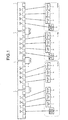
- FIG. 1 is a diagram illustrating a configuration example of a network system including communication apparatuses according to the present embodiment. Physical connections of apparatuses are shown.
- the network system includes communication apparatuses 1, 2, 3, and 4.
- the communication apparatuses 1 and 2 are connected by a Trunk Link 5.
- the communication apparatuses 2 and 3 are connected by a Trunk Link 6.
- the communication apparatuses 3 and 4 are connected by a Trunk Link 7.
- the communication apparatuses 1 to 4 each include a plurality of connection ports.
- the communication apparatuses 1 to 4 can perform VLAN settings by using VLAN numbers set for the connection ports.
- a specific example of the network system is a system in which, in a train formation, a communication apparatus in provided in each car and communication is performed among the cars by connecting the cars through Trunk Links. However, the network system is not limited to such communication among the cars.
- FIG. 2 is a diagram illustrating the state of a normal network conforming to VLAN settings.
- the management apparatus 10 and the apparatuses 11 to 16 are connected to a network of a VLAN #1.
- the management apparatus 10 and the apparatuses 11 to 16 can perform communication only in the network set by this port VLAN #1.
- the management apparatus 20 and the apparatuses 21 to 23 are connected to a network of a VLAN #2.
- the management apparatus 20 and the apparatuses 21 to 23 can perform communication only in the network set by this port VLAN #2.
- the management apparatus 30 and the apparatuses 31 to 33 are connected to a network of a VLAN #3.
- the management apparatus 30 and the apparatuses 31 to 33 can perform communication only in the network set by this port VLAN #3.
- a system is conceivable in which one communication apparatus is arranged in each of the cars and a VLAN is set for each of the cars.
- a management apparatus that manages communication of a corresponding VLAN.
- an apparatus connected to each communication apparatus there are, for example, a guidance display apparatus, a destination display apparatus, and a sound data output apparatus.
- apparatuses connected to each communication apparatus are not limited to these apparatuses.
- a microphone an apparatus connected to a communication apparatus of any car is used to output sound data from sound data output apparatuses connected to communication apparatuses of all cars in a train formation.
- a specific type of packet is used. The specific type indicates a port number corresponding to "80" or "110" in TCP/UDP, an IP address, a MAC address, or the like.
- the apparatus on the transmission side performs communication using a specific multicast address.
- a multicast address is set as an IP address
- a MAC address can also be determined.
- passage permission is set in a table or the like included in its own apparatus in advance for the specific type of packet, whereby a packet for disabling the VLANs can be defined in the system.
- FIG. 3 is a diagram illustrating the state of a network when the specific type of packet is used.
- the state of the network in the case of multicast is explained.
- the apparatus 11 transmits data to the apparatuses connected to the networks of the VLANs having the same and different settings, the apparatus 11 transmits the specific type of packet in multicast.
- each communication apparatus sets passage permission for the multicast address. Multicast addresses permitted to pass are set in advance in each communication apparatus. Note that, in each communication apparatus, the multicast address is not permitted to pass through the connection port to which the management apparatus is connected. Consequently, in each communication apparatus, apparatuses connected to ports for which passage permission is set in advance can receive data in multicast. On the other hand, the management apparatuses cannot receive data in multicast according to a packet filtering function.
- the apparatus 11 transmits the specific type of packet to the communication apparatus 1.
- the communication apparatus 1 transfers the specific type of packet received from the apparatus 11 to the apparatuses 12 and 13 that are desired destinations and the communication apparatus 2.
- the communication apparatus 2 transfers the specific type of packet received from the communication apparatus 1 to the apparatuses 14 to 16 that are desired destinations.
- the communication apparatus 2 transfers the specific type of packet received from the communication apparatus 1 to the communication apparatus 3.
- the communication apparatus 3 transfers the specific type of packet received from the communication apparatus 2 to the apparatuses 21 to 23 that are desired destinations and the communication apparatus 4.
- the communication apparatus 4 transfers the specific type of packet received from the communication apparatus 3 to the apparatuses 31 to 33 that are desired destinations.
- the communication apparatuses 3 and 4 disable the settings of the port VLANs and operate while regarding the networks of the VLAN #2 and the VLAN #3, respectively, as the same network as the VLAN #1.
- FIG. 4 is a diagram illustrating the state of a network when the specific type of packet is used.
- the state of the network in the case of unicast is explained here.
- the apparatus 11 transmits data to the apparatus 31 connected to the network of the VLAN having a different setting
- the apparatus 11 transmits the specific type of packet in unicast.
- each communication apparatus sets passage permission for the unicast address. Unicast addresses permitted to pass are set in advance in each communication apparatus.
- the apparatus 11 transmits the specific type of packet to the communication apparatus 1.
- the communication apparatus 1 transfers the specific type of packet received from the apparatus 11 to the communication apparatus 2.
- the communication apparatus 2 transfers the specific type of packet received from the communication apparatus 1 to the communication apparatus 3.
- the communication apparatus 3 transfers the specific type of packet received from the communication apparatus 2 to the communication apparatus 4.
- the communication apparatus 4 transfers the specific type of packet received from the communication apparatus 3 to the apparatus 31 that is a desired destination.
- the communication apparatuses 3 and 4 disable the settings of the port VLANs and operate while regarding the networks of the VLAN #2 and the VLAN #3, respectively, as the same network as the VLAN #1.
- a communication apparatus that has received a specific type of packet regards a plurality of VLANs as the same network and transfers the received packet to apparatuses that are connected to the connection ports and are desired destinations and adjacent communication apparatuses. Consequently, in a system that shares a network, it is possible to perform communication among networks having different VLAN settings.
Landscapes
- Engineering & Computer Science (AREA)
- Computer Networks & Wireless Communication (AREA)
- Signal Processing (AREA)
- Computer Security & Cryptography (AREA)
- Small-Scale Networks (AREA)
- Data Exchanges In Wide-Area Networks (AREA)
Abstract
Description
- The present invention relates to a network system and a communication apparatus that perform communication by VLANs.
- Communication using VLANs (Virtual Local Area Networks) has been performed. In a system that shares a network, the VLANs can divide and use the network. For example, in a system in which a plurality of communication apparatuses (hubs) are connected, by performing VLAN settings on the connection ports of the communication apparatuses (the hubs), one network in physical arrangement can be logically operated as a plurality of networks. Such a technology is disclosed in
Patent Literatures 1 to 3. -
- Patent Literature 1: Japanese Patent Application Laid-Open No.
2007-5892 - Patent Literature 2: Japanese Patent Application Laid-Open No.
2003-198588 - Patent Literature 3: Japanese Patent Application Laid-Open No.
2004-72160 - However, according to the conventional technology, communication can be performed only in the network having the same VLAN setting. Therefore, there is a problem in that communication cannot be performed among communication apparatuses having different VLAN settings even if a plurality of communication apparatuses are connected.
- The present invention has been devised in view of the above, and it is an object of the present invention to obtain a network system and a communication apparatus that can perform communication among communication apparatuses having different VLAN settings.
- In order to solve the above problems and achieve the object, the present invention relates to a network system that comprises a plurality of communication apparatuses, each of the communication apparatuses being capable of performing a VLAN setting by using a VLAN number set for a connection port, that sets a VLAN number for each of the communication apparatuses, and that performs communication among cars of a train, wherein in a case where a specific type of packet that disables a VLAN setting is a packet of a multicast address, when a distribution target apparatus is connected to a communication apparatus that has received the specific type of packet, the communication apparatus transfers the specific type of packet to the distribution target apparatus and, irrespective of a VLAN number set for another communication apparatus, regards a VLAN different from a VLAN of the communication apparatus as a same network and transfers the specific type of packet to the another communication apparatus.
- The network system according to the present invention attains an effect that it is possible to perform communication among communication apparatuses having different VLAN settings.
-
-
FIG. 1 is a diagram illustrating a configuration example of a network system including communication apparatuses. -
FIG. 2 is a diagram illustrating the state of a normal network conforming to VLAN settings. -
FIG. 3 is a diagram illustrating the state of a network when a specific type of packet is used. -
FIG. 4 is a diagram illustrating the state of a network when the specific type of packet is used. - Exemplary embodiments of a network system and a communication apparatus according to the present invention are explained in detail below with reference to the drawings. Note that the present invention is not limited to the embodiments.
-
FIG. 1 is a diagram illustrating a configuration example of a network system including communication apparatuses according to the present embodiment. Physical connections of apparatuses are shown. The network system includescommunication apparatuses communication apparatuses communication apparatuses communication apparatuses - A
management apparatus 10 andapparatuses 11 to 13, which are connected to theVLAN # 1 setting ports, are connected to thecommunication apparatus 1.Apparatuses 14 to 16, which are connected to theVLAN # 1 setting ports, are connected to thecommunication apparatus 2. Amanagement apparatus 20 andapparatuses 21 to 23, which are connected to theVLAN # 2 setting ports, are connected to thecommunication apparatus 3. Amanagement apparatus 30 andapparatuses 31 to 33, which are connected to theVLAN # 3 setting ports, are connected to thecommunication apparatus 4. Thecommunication apparatuses 1 to 4 each include a plurality of connection ports. Thecommunication apparatuses 1 to 4 can perform VLAN settings by using VLAN numbers set for the connection ports. A specific example of the network system is a system in which, in a train formation, a communication apparatus in provided in each car and communication is performed among the cars by connecting the cars through Trunk Links. However, the network system is not limited to such communication among the cars. -
FIG. 2 is a diagram illustrating the state of a normal network conforming to VLAN settings. As shown inFIG. 2 , themanagement apparatus 10 and theapparatuses 11 to 16 are connected to a network of aVLAN # 1. Usually, themanagement apparatus 10 and theapparatuses 11 to 16 can perform communication only in the network set by thisport VLAN # 1. Themanagement apparatus 20 and theapparatuses 21 to 23 are connected to a network of aVLAN # 2. Usually, themanagement apparatus 20 and theapparatuses 21 to 23 can perform communication only in the network set by thisport VLAN # 2. Themanagement apparatus 30 and theapparatuses 31 to 33 are connected to a network of aVLAN # 3. Usually, themanagement apparatus 30 and theapparatuses 31 to 33 can perform communication only in the network set by thisport VLAN # 3. - When communication is performed among cars, for example, a system is conceivable in which one communication apparatus is arranged in each of the cars and a VLAN is set for each of the cars. As an apparatus connected to each communication apparatus, there is a management apparatus that manages communication of a corresponding VLAN. As an apparatus connected to each communication apparatus, there are, for example, a guidance display apparatus, a destination display apparatus, and a sound data output apparatus. However, apparatuses connected to each communication apparatus are not limited to these apparatuses.
- Next, an explanation will be made of a case where communication is performed by a certain apparatus with apparatuses connected to communication apparatuses of other VLAN settings. Specifically, a microphone (an apparatus) connected to a communication apparatus of any car is used to output sound data from sound data output apparatuses connected to communication apparatuses of all cars in a train formation. When a certain apparatus performs communication with apparatuses connected to other VLANs, in the present embodiment, a specific type of packet is used. The specific type indicates a port number corresponding to "80" or "110" in TCP/UDP, an IP address, a MAC address, or the like. For example, when one apparatus transmits data to apparatuses connected to networks of VLANs having the same and different settings, the apparatus on the transmission side performs communication using a specific multicast address. When a multicast address is set as an IP address, a MAC address can also be determined. In each communication apparatus, passage permission is set in a table or the like included in its own apparatus in advance for the specific type of packet, whereby a packet for disabling the VLANs can be defined in the system.
-
FIG. 3 is a diagram illustrating the state of a network when the specific type of packet is used. The state of the network in the case of multicast is explained. For example, when theapparatus 11 transmits data to the apparatuses connected to the networks of the VLANs having the same and different settings, theapparatus 11 transmits the specific type of packet in multicast. In this case, in the connection ports to which the apparatuses are connected, each communication apparatus sets passage permission for the multicast address. Multicast addresses permitted to pass are set in advance in each communication apparatus. Note that, in each communication apparatus, the multicast address is not permitted to pass through the connection port to which the management apparatus is connected. Consequently, in each communication apparatus, apparatuses connected to ports for which passage permission is set in advance can receive data in multicast. On the other hand, the management apparatuses cannot receive data in multicast according to a packet filtering function. - Specifically, when the
apparatus 11 communicates with theapparatuses 12 to 16 on theVLAN # 1 side, theapparatuses 21 to 23 on theVLAN # 2 side, and theapparatuses 31 to 33 on theVLAN # 3 side, theapparatus 11 transmits the specific type of packet to thecommunication apparatus 1. Thecommunication apparatus 1 transfers the specific type of packet received from theapparatus 11 to theapparatuses communication apparatus 2. Thecommunication apparatus 2 transfers the specific type of packet received from thecommunication apparatus 1 to theapparatuses 14 to 16 that are desired destinations. Moreover, irrespective of the setting of the port VLANs (ignoring the setting of the port VLANs), thecommunication apparatus 2 transfers the specific type of packet received from thecommunication apparatus 1 to thecommunication apparatus 3. Irrespective of the setting of the port VLANs (ignoring the setting of the port VLANs), thecommunication apparatus 3 transfers the specific type of packet received from thecommunication apparatus 2 to theapparatuses 21 to 23 that are desired destinations and thecommunication apparatus 4. Irrespective of the setting of the port VLANs (ignoring the setting of the port VLANs), thecommunication apparatus 4 transfers the specific type of packet received from thecommunication apparatus 3 to theapparatuses 31 to 33 that are desired destinations. - As explained above, when receiving the specific type of packet from the
apparatus 11, thecommunication apparatuses VLAN # 2 and theVLAN # 3, respectively, as the same network as theVLAN # 1. - Note that communication among the VLANs is not limited to multicast and can also be performed in unicast.
FIG. 4 is a diagram illustrating the state of a network when the specific type of packet is used. The state of the network in the case of unicast is explained here. For example, when theapparatus 11 transmits data to theapparatus 31 connected to the network of the VLAN having a different setting, theapparatus 11 transmits the specific type of packet in unicast. In this case, as explained above, in the connection ports to which the apparatuses are connected, each communication apparatus sets passage permission for the unicast address. Unicast addresses permitted to pass are set in advance in each communication apparatus. - Specifically, when the
apparatus 11 communicates with theapparatus 31 on theVLAN # 3 side, theapparatus 11 transmits the specific type of packet to thecommunication apparatus 1. Thecommunication apparatus 1 transfers the specific type of packet received from theapparatus 11 to thecommunication apparatus 2. Irrespective of the setting of the port VLANs (ignoring the setting of the port VLANs), thecommunication apparatus 2 transfers the specific type of packet received from thecommunication apparatus 1 to thecommunication apparatus 3. Irrespective of the setting of the port VLANs (ignoring the setting of the port VLANs), thecommunication apparatus 3 transfers the specific type of packet received from thecommunication apparatus 2 to thecommunication apparatus 4. Irrespective of the setting of the port VLANs (ignoring the setting of the port VLANs), thecommunication apparatus 4 transfers the specific type of packet received from thecommunication apparatus 3 to theapparatus 31 that is a desired destination. - As in the case of multicast, when receiving the specific type of packet from the
apparatus 11, thecommunication apparatuses VLAN # 2 and theVLAN # 3, respectively, as the same network as theVLAN # 1. - As explained above, according to the present embodiment, in a network system configured from a plurality of communication apparatuses, irrespective of the VLAN settings, a communication apparatus that has received a specific type of packet regards a plurality of VLANs as the same network and transfers the received packet to apparatuses that are connected to the connection ports and are desired destinations and adjacent communication apparatuses. Consequently, in a system that shares a network, it is possible to perform communication among networks having different VLAN settings.
- 1, 2, 3, 4 communication apparatus, 5, 6, 7 Trunk Link, 10, 20, 30 management apparatus, 11 to 16, 21 to 23, 31 to 33 apparatus.
Claims (6)
- A network system that comprises a plurality of communication apparatuses, each of the communication apparatuses being capable of performing a VLAN setting by using a VLAN number set for a connection port, that sets a VLAN number for each of the communication apparatuses, and that performs communication among cars of a train, wherein
in a case where a specific type of packet that disables a VLAN setting is a packet of a multicast address, when a distribution target apparatus is connected to a communication apparatus that has received the specific type of packet, the communication apparatus transfers the specific type of packet to the distribution target apparatus and, irrespective of a VLAN number set for another communication apparatus, regards a VLAN different from a VLAN of the communication apparatus as a same network and transfers the specific type of packet to the another communication apparatus. - A network system that comprises a plurality of communication apparatuses, each of the communication apparatuses being capable of performing a VLAN setting by using a VLAN number set for a connection port, that sets a VLAN number for each of the communication apparatuses, and that performs communication among cars of a train, wherein
in a case where a specific type of packet that disables a VLAN setting is a packet of a unicast address, when a destination of the specific type of packet is an apparatus connected to a communication apparatus that has received the specific type of packet, the communication apparatus transfers the packet to the apparatus at a desired destination and, when a destination of the specific type of packet is an apparatus connected to another communication apparatus, irrespective of a VLAN number set for the another communication apparatus, the communication apparatus regards a VLAN different from a VLAN of the communication apparatus as a same network and transfers the specific type of packet to the another communication apparatus. - The network system according to claim 1 or 2, wherein the specific type of packet is a packet having a specific MAC address.
- A communication apparatus in a network system that comprises a plurality of communication apparatuses, each of the communication apparatuses being capable of performing a VLAN setting by using a VLAN number set for a connection port, that sets a VLAN number for each of the communication apparatuses, and that performs communication among cars of a train, wherein
in a case where the communication apparatus receives a packet of a multicast address as a specific type of packet that disables a VLAN setting, when a distribution target apparatus is connected to the communication apparatus, the communication apparatus transfers the specific type of packet to the distribution target apparatus and, irrespective of a VLAN number set for another communication apparatus, regards a VLAN different from a VLAN of the communication apparatus as a same network and transfers the specific type of packet to the another communication apparatus. - A communication apparatus in a network system that comprises a plurality of communication apparatuses, each of the communication apparatuses being capable of performing a VLAN setting by using a VLAN number set for a connection port, that sets a VLAN number for each of the communication apparatuses, and that performs communication among cars of a train, wherein
in a case where the communication apparatus receives a packet of a unicast address as a specific type of packet that disables a VLAN setting, when a destination of the specific type of packet is an apparatus connected to the communication apparatus, the communication apparatus transfers the packet to the apparatus at a desired destination and, when a destination of the specific type of packet is an apparatus connected to another communication apparatus, irrespective of a VLAN number set for the another communication apparatus, the communication apparatus regards a VLAN different from a VLAN of the communication apparatus as a same network and transfers the specific type of packet to the another communication apparatus. - The communication apparatus according to claim 4 or 5, wherein the specific type of packet is a packet having a specific MAC address.
Applications Claiming Priority (1)
| Application Number | Priority Date | Filing Date | Title |
|---|---|---|---|
| PCT/JP2012/071690 WO2014033835A1 (en) | 2012-08-28 | 2012-08-28 | Network system and communication apparatuses |
Publications (3)
| Publication Number | Publication Date |
|---|---|
| EP2892185A1 true EP2892185A1 (en) | 2015-07-08 |
| EP2892185A4 EP2892185A4 (en) | 2016-05-18 |
| EP2892185B1 EP2892185B1 (en) | 2018-03-07 |
Family
ID=49396768
Family Applications (1)
| Application Number | Title | Priority Date | Filing Date |
|---|---|---|---|
| EP12883460.3A Not-in-force EP2892185B1 (en) | 2012-08-28 | 2012-08-28 | Network system and communication apparatuses |
Country Status (6)
| Country | Link |
|---|---|
| US (1) | US9923733B2 (en) |
| EP (1) | EP2892185B1 (en) |
| JP (1) | JP5295463B1 (en) |
| CN (1) | CN104604186B (en) |
| TW (1) | TWI482463B (en) |
| WO (1) | WO2014033835A1 (en) |
Cited By (1)
| Publication number | Priority date | Publication date | Assignee | Title |
|---|---|---|---|---|
| WO2018158084A1 (en) * | 2017-02-28 | 2018-09-07 | Audi Ag | Motor vehicle having a data network which is divided into multiple separate domains and method for operating the data network |
Families Citing this family (4)
| Publication number | Priority date | Publication date | Assignee | Title |
|---|---|---|---|---|
| US10017195B2 (en) * | 2014-01-27 | 2018-07-10 | Mitsubishi Electric Corporation | Communication device, train network system, and network setting method |
| CN105591968B (en) * | 2016-01-25 | 2019-05-03 | 盛科网络(苏州)有限公司 | A kind of implementation method that balanced ethernet network storm inhibits |
| WO2019058659A1 (en) * | 2017-09-19 | 2019-03-28 | 日本電気株式会社 | Communication system, transfer device, communication control method, and non-temporary computer readable medium that stores program |
| CN114553634B (en) * | 2020-11-24 | 2024-08-23 | 上海汽车集团股份有限公司 | Data processing method and related device |
Family Cites Families (33)
| Publication number | Priority date | Publication date | Assignee | Title |
|---|---|---|---|---|
| US6112251A (en) * | 1998-01-13 | 2000-08-29 | Cabletron Systems, Inc. | Virtual local network for sending multicast transmissions to trunk stations |
| US6115385A (en) * | 1998-03-11 | 2000-09-05 | Cisco Technology, Inc. | Method and system for subnetting in a switched IP network |
| JP3510489B2 (en) | 1998-07-28 | 2004-03-29 | 富士通アイ・ネットワークシステムズ株式会社 | Front plate structure of package with electronic circuit |
| US6912589B1 (en) * | 1999-03-30 | 2005-06-28 | 3Com Corportion | System and method for efficiently handling multicast packets by ignoring VLAN context |
| US6765914B1 (en) * | 2000-04-07 | 2004-07-20 | 3Com Corporation | Generic switch architecture to support flexible subnets across layer-3 devices |
| KR20020017265A (en) * | 2000-08-29 | 2002-03-07 | 구자홍 | Communication method for plural virtual lan consisted in identical ip subnet |
| US7301946B2 (en) | 2000-11-22 | 2007-11-27 | Cisco Technology, Inc. | System and method for grouping multiple VLANs into a single 802.11 IP multicast domain |
| JP2003032287A (en) * | 2001-07-16 | 2003-01-31 | Furukawa Electric Co Ltd:The | Network connection method, device thereof, and system using the device |
| JP4236398B2 (en) | 2001-08-15 | 2009-03-11 | 富士通株式会社 | Communication method, communication system, and communication connection program |
| JP3803963B2 (en) * | 2001-12-28 | 2006-08-02 | 松下電器産業株式会社 | Subnet connection switching communication system |
| JP2004072160A (en) | 2002-08-01 | 2004-03-04 | Matsushita Electric Ind Co Ltd | Switching method and apparatus, and computer program |
| AU2002325503A1 (en) * | 2002-08-07 | 2004-02-25 | Allied Telesis K.K. | Transmission system, and method thereof |
| JP3886432B2 (en) | 2002-09-17 | 2007-02-28 | 沖電気工業株式会社 | Routing processing device and packet type identification device |
| US7317722B2 (en) * | 2003-08-20 | 2008-01-08 | 3Com Corporation | System and method for distributed multicast routing |
| JP4053967B2 (en) | 2003-11-20 | 2008-02-27 | 株式会社日立コミュニケーションテクノロジー | VLAN server |
| DE60323275D1 (en) | 2003-12-16 | 2008-10-09 | Ericsson Telefon Ab L M | ETHERNET DSL ACCESS MULTIPLEXER AND METHOD FOR PROVIDING A DYNAMIC SERVICE SELECTION AND END-USER CONFIGURATION |
| US7860097B1 (en) * | 2004-02-13 | 2010-12-28 | Habanero Holdings, Inc. | Fabric-backplane enterprise servers with VNICs and VLANs |
| US8037204B2 (en) * | 2005-02-11 | 2011-10-11 | Cisco Technology, Inc. | Method and system for IP train inauguration |
| JP2007005892A (en) | 2005-06-21 | 2007-01-11 | Nec Corp | Information distribution system, information distribution method, wireless lan terminal, information acquisition method of wireless lan terminal, and access point |
| JP4799118B2 (en) * | 2005-10-14 | 2011-10-26 | 株式会社ソニー・コンピュータエンタテインメント | Information processing apparatus, information processing system, communication relay apparatus, and communication control method |
| KR100694296B1 (en) * | 2005-11-08 | 2007-03-14 | 한국전자통신연구원 | System for providing 2 layer multicast switching and 3 layer multicast routing simultaneously based on virtual interface |
| JP4834410B2 (en) * | 2006-01-26 | 2011-12-14 | 株式会社日立製作所 | Frame transfer device |
| TWI325705B (en) * | 2006-06-01 | 2010-06-01 | Via Tech Inc | Method and apparatus for packet switching |
| CN100461732C (en) | 2006-06-16 | 2009-02-11 | 华为技术有限公司 | A method, system and device for switching and forwarding Ethernet technology |
| US7768918B2 (en) * | 2006-06-28 | 2010-08-03 | Via Technologies Inc. | Method for expanding the service VLAN space of a provider network |
| TWI324456B (en) * | 2006-12-01 | 2010-05-01 | Cameo Communications Inc | An intelligent automatic setting restoration method and device |
| US7940766B2 (en) * | 2006-12-08 | 2011-05-10 | Alcatel Lucent | Multicasting unicast packet/multiple classification of a packet |
| TWI325707B (en) * | 2006-12-26 | 2010-06-01 | Ind Tech Res Inst | Packet classifier for a network and method thereof |
| JP2009278317A (en) | 2008-05-14 | 2009-11-26 | Chuden Cti Co Ltd | Network driver, computer incorporated with the network driver and server |
| JP5314579B2 (en) | 2009-11-25 | 2013-10-16 | パナソニック株式会社 | Network monitoring and control device |
| JP5595768B2 (en) | 2010-03-25 | 2014-09-24 | コイト電工株式会社 | VEHICLE NETWORK VEHICLE NETWORK SYSTEM AND VEHICLE NETWORK CONTROL DEVICE |
| US8374182B2 (en) | 2010-08-13 | 2013-02-12 | Juniper Networks, Inc. | Virtual local area network (VLAN)-based membership for multicast VLAN registration |
| CA2732181C (en) * | 2011-02-18 | 2017-08-29 | Ruggedcom Inc. | Stand alone wimax system and method |
-
2012
- 2012-08-28 EP EP12883460.3A patent/EP2892185B1/en not_active Not-in-force
- 2012-08-28 US US14/423,738 patent/US9923733B2/en not_active Expired - Fee Related
- 2012-08-28 JP JP2013500254A patent/JP5295463B1/en active Active
- 2012-08-28 CN CN201280075425.8A patent/CN104604186B/en not_active Expired - Fee Related
- 2012-08-28 WO PCT/JP2012/071690 patent/WO2014033835A1/en not_active Ceased
-
2013
- 2013-01-03 TW TW102100089A patent/TWI482463B/en not_active IP Right Cessation
Cited By (3)
| Publication number | Priority date | Publication date | Assignee | Title |
|---|---|---|---|---|
| WO2018158084A1 (en) * | 2017-02-28 | 2018-09-07 | Audi Ag | Motor vehicle having a data network which is divided into multiple separate domains and method for operating the data network |
| CN110290980A (en) * | 2017-02-28 | 2019-09-27 | 奥迪股份公司 | Motor vehicle with data network divided into several separate domains and method for operating a data network |
| US11438343B2 (en) | 2017-02-28 | 2022-09-06 | Audi Ag | Motor vehicle having a data network which is divided into multiple separate domains and method for operating the data network |
Also Published As
| Publication number | Publication date |
|---|---|
| WO2014033835A1 (en) | 2014-03-06 |
| TWI482463B (en) | 2015-04-21 |
| JP5295463B1 (en) | 2013-09-18 |
| CN104604186A (en) | 2015-05-06 |
| TW201409976A (en) | 2014-03-01 |
| US20150244543A1 (en) | 2015-08-27 |
| EP2892185A4 (en) | 2016-05-18 |
| CN104604186B (en) | 2018-09-11 |
| US9923733B2 (en) | 2018-03-20 |
| JPWO2014033835A1 (en) | 2016-08-08 |
| EP2892185B1 (en) | 2018-03-07 |
Similar Documents
| Publication | Publication Date | Title |
|---|---|---|
| EP2629459A3 (en) | Avionics full-duplex switched ethernet network | |
| US9923733B2 (en) | Network system and communication apparatus for performing communication among networks having different VLAN settings | |
| CN102710669B (en) | A kind of method that firewall policy controls and device | |
| US9071539B2 (en) | Method for avoiding a loop in a network | |
| WO2014182814A3 (en) | Transport mode for wireless serial bus (wsb) service | |
| EP2605462B1 (en) | Methods and apparatus for implementing a fibre channel zone policy | |
| CN102427429B (en) | A kind of realize the method for switch built-in message security protection, system and switch | |
| GB2514323A (en) | Multiple virtual machines sharing a single IP address | |
| WO2009126447A3 (en) | Discovery for fibre channel over ethernet devices | |
| WO2011087603A3 (en) | Decoupled cascaded mixers architecture and related methods | |
| MX2009012490A (en) | An ethernet protection switching system. | |
| CN103763207A (en) | In-band control connection establishment method and device in SDN | |
| WO2015177789A8 (en) | A method for establishing a secure private interconnection over a multipath network | |
| CN105847185A (en) | Message processing method and apparatus for distributed device and distributed device | |
| CN109379297A (en) | A kind of method and apparatus for realizing flow load balance | |
| EP4686166A3 (en) | Systems, apparatuses and methods for cooperating routers | |
| CN103812752B (en) | In a kind of power telecom network between VLAN resource-sharing method | |
| CN101631062A (en) | PVLAN implementation method of trunking port isolation | |
| CN102857429A (en) | Method and device for carrying route in transparent interconnection of lots of links (TRILL) network | |
| WO2012143943A3 (en) | Multi-host ethernet controller | |
| EP2618527A3 (en) | Dynamic virtual LANs to segregate data | |
| WO2013141191A1 (en) | Control apparatus, communication system, node control method and program | |
| CN104641594B (en) | Multicast message updates | |
| EP3059910A1 (en) | Method and device for redundancy protection | |
| US9531567B2 (en) | Network system |
Legal Events
| Date | Code | Title | Description |
|---|---|---|---|
| PUAI | Public reference made under article 153(3) epc to a published international application that has entered the european phase |
Free format text: ORIGINAL CODE: 0009012 |
|
| 17P | Request for examination filed |
Effective date: 20150211 |
|
| AK | Designated contracting states |
Kind code of ref document: A1 Designated state(s): AL AT BE BG CH CY CZ DE DK EE ES FI FR GB GR HR HU IE IS IT LI LT LU LV MC MK MT NL NO PL PT RO RS SE SI SK SM TR |
|
| AX | Request for extension of the european patent |
Extension state: BA ME |
|
| DAX | Request for extension of the european patent (deleted) | ||
| RA4 | Supplementary search report drawn up and despatched (corrected) |
Effective date: 20160414 |
|
| RIC1 | Information provided on ipc code assigned before grant |
Ipc: H04L 12/44 20060101ALI20160408BHEP Ipc: H04L 12/40 20060101ALN20160408BHEP Ipc: H04L 12/18 20060101ALI20160408BHEP Ipc: H04L 12/46 20060101AFI20160408BHEP |
|
| 17Q | First examination report despatched |
Effective date: 20161212 |
|
| REG | Reference to a national code |
Ref country code: DE Ref legal event code: R079 Ref document number: 602012043889 Country of ref document: DE Free format text: PREVIOUS MAIN CLASS: H04L0012440000 Ipc: H04L0012460000 |
|
| GRAP | Despatch of communication of intention to grant a patent |
Free format text: ORIGINAL CODE: EPIDOSNIGR1 |
|
| RIC1 | Information provided on ipc code assigned before grant |
Ipc: H04L 12/40 20060101ALN20170914BHEP Ipc: H04L 12/44 20060101ALI20170914BHEP Ipc: H04L 12/18 20060101ALI20170914BHEP Ipc: H04L 12/46 20060101AFI20170914BHEP |
|
| INTG | Intention to grant announced |
Effective date: 20171005 |
|
| GRAS | Grant fee paid |
Free format text: ORIGINAL CODE: EPIDOSNIGR3 |
|
| GRAA | (expected) grant |
Free format text: ORIGINAL CODE: 0009210 |
|
| AK | Designated contracting states |
Kind code of ref document: B1 Designated state(s): AL AT BE BG CH CY CZ DE DK EE ES FI FR GB GR HR HU IE IS IT LI LT LU LV MC MK MT NL NO PL PT RO RS SE SI SK SM TR |
|
| REG | Reference to a national code |
Ref country code: GB Ref legal event code: FG4D |
|
| REG | Reference to a national code |
Ref country code: CH Ref legal event code: EP Ref country code: AT Ref legal event code: REF Ref document number: 977684 Country of ref document: AT Kind code of ref document: T Effective date: 20180315 |
|
| REG | Reference to a national code |
Ref country code: IE Ref legal event code: FG4D |
|
| REG | Reference to a national code |
Ref country code: DE Ref legal event code: R096 Ref document number: 602012043889 Country of ref document: DE |
|
| REG | Reference to a national code |
Ref country code: NL Ref legal event code: MP Effective date: 20180307 |
|
| REG | Reference to a national code |
Ref country code: LT Ref legal event code: MG4D |
|
| PG25 | Lapsed in a contracting state [announced via postgrant information from national office to epo] |
Ref country code: CY Free format text: LAPSE BECAUSE OF FAILURE TO SUBMIT A TRANSLATION OF THE DESCRIPTION OR TO PAY THE FEE WITHIN THE PRESCRIBED TIME-LIMIT Effective date: 20180307 Ref country code: LT Free format text: LAPSE BECAUSE OF FAILURE TO SUBMIT A TRANSLATION OF THE DESCRIPTION OR TO PAY THE FEE WITHIN THE PRESCRIBED TIME-LIMIT Effective date: 20180307 Ref country code: HR Free format text: LAPSE BECAUSE OF FAILURE TO SUBMIT A TRANSLATION OF THE DESCRIPTION OR TO PAY THE FEE WITHIN THE PRESCRIBED TIME-LIMIT Effective date: 20180307 Ref country code: ES Free format text: LAPSE BECAUSE OF FAILURE TO SUBMIT A TRANSLATION OF THE DESCRIPTION OR TO PAY THE FEE WITHIN THE PRESCRIBED TIME-LIMIT Effective date: 20180307 Ref country code: FI Free format text: LAPSE BECAUSE OF FAILURE TO SUBMIT A TRANSLATION OF THE DESCRIPTION OR TO PAY THE FEE WITHIN THE PRESCRIBED TIME-LIMIT Effective date: 20180307 Ref country code: NO Free format text: LAPSE BECAUSE OF FAILURE TO SUBMIT A TRANSLATION OF THE DESCRIPTION OR TO PAY THE FEE WITHIN THE PRESCRIBED TIME-LIMIT Effective date: 20180607 |
|
| REG | Reference to a national code |
Ref country code: AT Ref legal event code: MK05 Ref document number: 977684 Country of ref document: AT Kind code of ref document: T Effective date: 20180307 |
|
| PG25 | Lapsed in a contracting state [announced via postgrant information from national office to epo] |
Ref country code: SE Free format text: LAPSE BECAUSE OF FAILURE TO SUBMIT A TRANSLATION OF THE DESCRIPTION OR TO PAY THE FEE WITHIN THE PRESCRIBED TIME-LIMIT Effective date: 20180307 Ref country code: RS Free format text: LAPSE BECAUSE OF FAILURE TO SUBMIT A TRANSLATION OF THE DESCRIPTION OR TO PAY THE FEE WITHIN THE PRESCRIBED TIME-LIMIT Effective date: 20180307 Ref country code: LV Free format text: LAPSE BECAUSE OF FAILURE TO SUBMIT A TRANSLATION OF THE DESCRIPTION OR TO PAY THE FEE WITHIN THE PRESCRIBED TIME-LIMIT Effective date: 20180307 Ref country code: GR Free format text: LAPSE BECAUSE OF FAILURE TO SUBMIT A TRANSLATION OF THE DESCRIPTION OR TO PAY THE FEE WITHIN THE PRESCRIBED TIME-LIMIT Effective date: 20180608 Ref country code: BG Free format text: LAPSE BECAUSE OF FAILURE TO SUBMIT A TRANSLATION OF THE DESCRIPTION OR TO PAY THE FEE WITHIN THE PRESCRIBED TIME-LIMIT Effective date: 20180607 |
|
| PG25 | Lapsed in a contracting state [announced via postgrant information from national office to epo] |
Ref country code: AL Free format text: LAPSE BECAUSE OF FAILURE TO SUBMIT A TRANSLATION OF THE DESCRIPTION OR TO PAY THE FEE WITHIN THE PRESCRIBED TIME-LIMIT Effective date: 20180307 Ref country code: NL Free format text: LAPSE BECAUSE OF FAILURE TO SUBMIT A TRANSLATION OF THE DESCRIPTION OR TO PAY THE FEE WITHIN THE PRESCRIBED TIME-LIMIT Effective date: 20180307 Ref country code: PL Free format text: LAPSE BECAUSE OF FAILURE TO SUBMIT A TRANSLATION OF THE DESCRIPTION OR TO PAY THE FEE WITHIN THE PRESCRIBED TIME-LIMIT Effective date: 20180307 Ref country code: RO Free format text: LAPSE BECAUSE OF FAILURE TO SUBMIT A TRANSLATION OF THE DESCRIPTION OR TO PAY THE FEE WITHIN THE PRESCRIBED TIME-LIMIT Effective date: 20180307 Ref country code: IT Free format text: LAPSE BECAUSE OF FAILURE TO SUBMIT A TRANSLATION OF THE DESCRIPTION OR TO PAY THE FEE WITHIN THE PRESCRIBED TIME-LIMIT Effective date: 20180307 Ref country code: EE Free format text: LAPSE BECAUSE OF FAILURE TO SUBMIT A TRANSLATION OF THE DESCRIPTION OR TO PAY THE FEE WITHIN THE PRESCRIBED TIME-LIMIT Effective date: 20180307 |
|
| PG25 | Lapsed in a contracting state [announced via postgrant information from national office to epo] |
Ref country code: SK Free format text: LAPSE BECAUSE OF FAILURE TO SUBMIT A TRANSLATION OF THE DESCRIPTION OR TO PAY THE FEE WITHIN THE PRESCRIBED TIME-LIMIT Effective date: 20180307 Ref country code: CZ Free format text: LAPSE BECAUSE OF FAILURE TO SUBMIT A TRANSLATION OF THE DESCRIPTION OR TO PAY THE FEE WITHIN THE PRESCRIBED TIME-LIMIT Effective date: 20180307 Ref country code: AT Free format text: LAPSE BECAUSE OF FAILURE TO SUBMIT A TRANSLATION OF THE DESCRIPTION OR TO PAY THE FEE WITHIN THE PRESCRIBED TIME-LIMIT Effective date: 20180307 Ref country code: SM Free format text: LAPSE BECAUSE OF FAILURE TO SUBMIT A TRANSLATION OF THE DESCRIPTION OR TO PAY THE FEE WITHIN THE PRESCRIBED TIME-LIMIT Effective date: 20180307 |
|
| REG | Reference to a national code |
Ref country code: DE Ref legal event code: R097 Ref document number: 602012043889 Country of ref document: DE |
|
| PG25 | Lapsed in a contracting state [announced via postgrant information from national office to epo] |
Ref country code: PT Free format text: LAPSE BECAUSE OF FAILURE TO SUBMIT A TRANSLATION OF THE DESCRIPTION OR TO PAY THE FEE WITHIN THE PRESCRIBED TIME-LIMIT Effective date: 20180709 |
|
| PLBE | No opposition filed within time limit |
Free format text: ORIGINAL CODE: 0009261 |
|
| STAA | Information on the status of an ep patent application or granted ep patent |
Free format text: STATUS: NO OPPOSITION FILED WITHIN TIME LIMIT |
|
| PG25 | Lapsed in a contracting state [announced via postgrant information from national office to epo] |
Ref country code: DK Free format text: LAPSE BECAUSE OF FAILURE TO SUBMIT A TRANSLATION OF THE DESCRIPTION OR TO PAY THE FEE WITHIN THE PRESCRIBED TIME-LIMIT Effective date: 20180307 |
|
| 26N | No opposition filed |
Effective date: 20181210 |
|
| PG25 | Lapsed in a contracting state [announced via postgrant information from national office to epo] |
Ref country code: SI Free format text: LAPSE BECAUSE OF FAILURE TO SUBMIT A TRANSLATION OF THE DESCRIPTION OR TO PAY THE FEE WITHIN THE PRESCRIBED TIME-LIMIT Effective date: 20180307 |
|
| PG25 | Lapsed in a contracting state [announced via postgrant information from national office to epo] |
Ref country code: MC Free format text: LAPSE BECAUSE OF FAILURE TO SUBMIT A TRANSLATION OF THE DESCRIPTION OR TO PAY THE FEE WITHIN THE PRESCRIBED TIME-LIMIT Effective date: 20180307 |
|
| REG | Reference to a national code |
Ref country code: CH Ref legal event code: PL |
|
| GBPC | Gb: european patent ceased through non-payment of renewal fee |
Effective date: 20180828 |
|
| PG25 | Lapsed in a contracting state [announced via postgrant information from national office to epo] |
Ref country code: CH Free format text: LAPSE BECAUSE OF NON-PAYMENT OF DUE FEES Effective date: 20180831 Ref country code: LU Free format text: LAPSE BECAUSE OF NON-PAYMENT OF DUE FEES Effective date: 20180828 Ref country code: LI Free format text: LAPSE BECAUSE OF NON-PAYMENT OF DUE FEES Effective date: 20180831 |
|
| REG | Reference to a national code |
Ref country code: BE Ref legal event code: MM Effective date: 20180831 |
|
| PG25 | Lapsed in a contracting state [announced via postgrant information from national office to epo] |
Ref country code: FR Free format text: LAPSE BECAUSE OF NON-PAYMENT OF DUE FEES Effective date: 20180831 Ref country code: BE Free format text: LAPSE BECAUSE OF NON-PAYMENT OF DUE FEES Effective date: 20180831 |
|
| PG25 | Lapsed in a contracting state [announced via postgrant information from national office to epo] |
Ref country code: GB Free format text: LAPSE BECAUSE OF NON-PAYMENT OF DUE FEES Effective date: 20180828 |
|
| PG25 | Lapsed in a contracting state [announced via postgrant information from national office to epo] |
Ref country code: MT Free format text: LAPSE BECAUSE OF NON-PAYMENT OF DUE FEES Effective date: 20180828 |
|
| PG25 | Lapsed in a contracting state [announced via postgrant information from national office to epo] |
Ref country code: TR Free format text: LAPSE BECAUSE OF FAILURE TO SUBMIT A TRANSLATION OF THE DESCRIPTION OR TO PAY THE FEE WITHIN THE PRESCRIBED TIME-LIMIT Effective date: 20180307 |
|
| PG25 | Lapsed in a contracting state [announced via postgrant information from national office to epo] |
Ref country code: MK Free format text: LAPSE BECAUSE OF NON-PAYMENT OF DUE FEES Effective date: 20180307 Ref country code: IE Free format text: LAPSE BECAUSE OF NON-PAYMENT OF DUE FEES Effective date: 20180828 Ref country code: HU Free format text: LAPSE BECAUSE OF FAILURE TO SUBMIT A TRANSLATION OF THE DESCRIPTION OR TO PAY THE FEE WITHIN THE PRESCRIBED TIME-LIMIT; INVALID AB INITIO Effective date: 20120828 |
|
| PG25 | Lapsed in a contracting state [announced via postgrant information from national office to epo] |
Ref country code: IS Free format text: LAPSE BECAUSE OF FAILURE TO SUBMIT A TRANSLATION OF THE DESCRIPTION OR TO PAY THE FEE WITHIN THE PRESCRIBED TIME-LIMIT Effective date: 20180707 |
|
| REG | Reference to a national code |
Ref country code: DE Ref legal event code: R084 Ref document number: 602012043889 Country of ref document: DE |
|
| PGFP | Annual fee paid to national office [announced via postgrant information from national office to epo] |
Ref country code: DE Payment date: 20210720 Year of fee payment: 10 |
|
| REG | Reference to a national code |
Ref country code: DE Ref legal event code: R119 Ref document number: 602012043889 Country of ref document: DE |
|
| PG25 | Lapsed in a contracting state [announced via postgrant information from national office to epo] |
Ref country code: DE Free format text: LAPSE BECAUSE OF NON-PAYMENT OF DUE FEES Effective date: 20230301 |