EP2892082A1 - Thermoelectric material and thermoelectric module - Google Patents
Thermoelectric material and thermoelectric module Download PDFInfo
- Publication number
- EP2892082A1 EP2892082A1 EP13833465.1A EP13833465A EP2892082A1 EP 2892082 A1 EP2892082 A1 EP 2892082A1 EP 13833465 A EP13833465 A EP 13833465A EP 2892082 A1 EP2892082 A1 EP 2892082A1
- Authority
- EP
- European Patent Office
- Prior art keywords
- thermoelectric
- pedot
- pss
- temperature
- illustrates
- Prior art date
- Legal status (The legal status is an assumption and is not a legal conclusion. Google has not performed a legal analysis and makes no representation as to the accuracy of the status listed.)
- Granted
Links
- 239000000463 material Substances 0.000 title claims abstract description 121
- LYCAIKOWRPUZTN-UHFFFAOYSA-N Ethylene glycol Chemical compound OCCO LYCAIKOWRPUZTN-UHFFFAOYSA-N 0.000 claims abstract description 216
- 238000004519 manufacturing process Methods 0.000 claims abstract description 33
- 238000000137 annealing Methods 0.000 claims abstract description 27
- IAZDPXIOMUYVGZ-UHFFFAOYSA-N Dimethylsulphoxide Chemical compound CS(C)=O IAZDPXIOMUYVGZ-UHFFFAOYSA-N 0.000 claims abstract description 24
- LFQSCWFLJHTTHZ-UHFFFAOYSA-N Ethanol Chemical compound CCO LFQSCWFLJHTTHZ-UHFFFAOYSA-N 0.000 claims abstract description 24
- 229920001467 poly(styrenesulfonates) Polymers 0.000 claims abstract description 17
- KFZMGEQAYNKOFK-UHFFFAOYSA-N Isopropanol Chemical compound CC(C)O KFZMGEQAYNKOFK-UHFFFAOYSA-N 0.000 claims abstract description 16
- 239000002904 solvent Substances 0.000 claims abstract description 16
- 239000011970 polystyrene sulfonate Substances 0.000 claims abstract description 14
- 229960002796 polystyrene sulfonate Drugs 0.000 claims abstract description 14
- JOXIMZWYDAKGHI-UHFFFAOYSA-N toluene-4-sulfonic acid Chemical compound CC1=CC=C(S(O)(=O)=O)C=C1 JOXIMZWYDAKGHI-UHFFFAOYSA-N 0.000 claims abstract description 13
- 239000000126 substance Substances 0.000 claims abstract description 10
- 229920001940 conductive polymer Polymers 0.000 claims abstract description 9
- VLTRZXGMWDSKGL-UHFFFAOYSA-N perchloric acid Chemical compound OCl(=O)(=O)=O VLTRZXGMWDSKGL-UHFFFAOYSA-N 0.000 claims abstract description 5
- VEXZGXHMUGYJMC-UHFFFAOYSA-M Chloride anion Chemical compound [Cl-] VEXZGXHMUGYJMC-UHFFFAOYSA-M 0.000 claims abstract description 3
- VLTRZXGMWDSKGL-UHFFFAOYSA-M perchlorate Inorganic materials [O-]Cl(=O)(=O)=O VLTRZXGMWDSKGL-UHFFFAOYSA-M 0.000 claims abstract description 3
- 229920001609 Poly(3,4-ethylenedioxythiophene) Polymers 0.000 claims description 34
- 238000000034 method Methods 0.000 claims description 34
- XLYOFNOQVPJJNP-UHFFFAOYSA-N water Substances O XLYOFNOQVPJJNP-UHFFFAOYSA-N 0.000 claims description 29
- 230000008569 process Effects 0.000 claims description 26
- -1 Poly(3,4-ethylenedioxythiophene) Polymers 0.000 claims description 19
- 238000007789 sealing Methods 0.000 claims description 7
- 239000000654 additive Substances 0.000 claims description 3
- 230000000996 additive effect Effects 0.000 claims description 3
- 239000010408 film Substances 0.000 description 90
- 229920000144 PEDOT:PSS Polymers 0.000 description 82
- 239000000758 substrate Substances 0.000 description 17
- 239000013078 crystal Substances 0.000 description 16
- 239000004065 semiconductor Substances 0.000 description 16
- 239000000243 solution Substances 0.000 description 16
- 238000005259 measurement Methods 0.000 description 14
- 239000007864 aqueous solution Substances 0.000 description 12
- 238000004458 analytical method Methods 0.000 description 10
- 238000001654 grazing-incidence X-ray scattering Methods 0.000 description 10
- 239000004020 conductor Substances 0.000 description 9
- 239000004205 dimethyl polysiloxane Substances 0.000 description 8
- 229910052751 metal Inorganic materials 0.000 description 8
- 239000002184 metal Substances 0.000 description 8
- 239000000123 paper Substances 0.000 description 8
- 229920000435 poly(dimethylsiloxane) Polymers 0.000 description 8
- 238000012545 processing Methods 0.000 description 8
- 239000002918 waste heat Substances 0.000 description 7
- 238000009835 boiling Methods 0.000 description 6
- 230000000694 effects Effects 0.000 description 6
- 239000002159 nanocrystal Substances 0.000 description 6
- 239000000523 sample Substances 0.000 description 6
- 230000005540 biological transmission Effects 0.000 description 5
- 230000007423 decrease Effects 0.000 description 5
- 230000003247 decreasing effect Effects 0.000 description 5
- 238000010586 diagram Methods 0.000 description 5
- 239000011521 glass Substances 0.000 description 5
- 238000002441 X-ray diffraction Methods 0.000 description 4
- 230000008859 change Effects 0.000 description 4
- 230000005611 electricity Effects 0.000 description 4
- 238000001704 evaporation Methods 0.000 description 4
- 230000008020 evaporation Effects 0.000 description 4
- 239000011368 organic material Substances 0.000 description 4
- 239000007787 solid Substances 0.000 description 4
- 239000010409 thin film Substances 0.000 description 4
- 230000006399 behavior Effects 0.000 description 3
- 238000006243 chemical reaction Methods 0.000 description 3
- 239000002019 doping agent Substances 0.000 description 3
- 230000007246 mechanism Effects 0.000 description 3
- CBXRMKZFYQISIV-UHFFFAOYSA-N 1-n,1-n,1-n',1-n',2-n,2-n,2-n',2-n'-octamethylethene-1,1,2,2-tetramine Chemical group CN(C)C(N(C)C)=C(N(C)C)N(C)C CBXRMKZFYQISIV-UHFFFAOYSA-N 0.000 description 2
- 230000005355 Hall effect Effects 0.000 description 2
- 230000005678 Seebeck effect Effects 0.000 description 2
- BQCADISMDOOEFD-UHFFFAOYSA-N Silver Chemical compound [Ag] BQCADISMDOOEFD-UHFFFAOYSA-N 0.000 description 2
- 239000000956 alloy Substances 0.000 description 2
- 229910045601 alloy Inorganic materials 0.000 description 2
- 238000005452 bending Methods 0.000 description 2
- 239000000969 carrier Substances 0.000 description 2
- 238000005266 casting Methods 0.000 description 2
- 238000012512 characterization method Methods 0.000 description 2
- 239000000460 chlorine Substances 0.000 description 2
- 239000002322 conducting polymer Substances 0.000 description 2
- 238000004134 energy conservation Methods 0.000 description 2
- 238000002474 experimental method Methods 0.000 description 2
- 238000003306 harvesting Methods 0.000 description 2
- 230000006872 improvement Effects 0.000 description 2
- 239000002985 plastic film Substances 0.000 description 2
- 229920006255 plastic film Polymers 0.000 description 2
- BASFCYQUMIYNBI-UHFFFAOYSA-N platinum Chemical compound [Pt] BASFCYQUMIYNBI-UHFFFAOYSA-N 0.000 description 2
- 229920000767 polyaniline Polymers 0.000 description 2
- 238000004736 wide-angle X-ray diffraction Methods 0.000 description 2
- 229910002899 Bi2Te3 Inorganic materials 0.000 description 1
- UJOBWOGCFQCDNV-UHFFFAOYSA-N Carbazole Natural products C1=CC=C2C3=CC=CC=C3NC2=C1 UJOBWOGCFQCDNV-UHFFFAOYSA-N 0.000 description 1
- OKTJSMMVPCPJKN-UHFFFAOYSA-N Carbon Chemical compound [C] OKTJSMMVPCPJKN-UHFFFAOYSA-N 0.000 description 1
- ZAMOUSCENKQFHK-UHFFFAOYSA-N Chlorine atom Chemical compound [Cl] ZAMOUSCENKQFHK-UHFFFAOYSA-N 0.000 description 1
- CBENFWSGALASAD-UHFFFAOYSA-N Ozone Chemical compound [O-][O+]=O CBENFWSGALASAD-UHFFFAOYSA-N 0.000 description 1
- 239000004642 Polyimide Substances 0.000 description 1
- 229920001328 Polyvinylidene chloride Polymers 0.000 description 1
- 238000000333 X-ray scattering Methods 0.000 description 1
- MKPXGEVFQSIKGE-UHFFFAOYSA-N [Mg].[Si] Chemical compound [Mg].[Si] MKPXGEVFQSIKGE-UHFFFAOYSA-N 0.000 description 1
- 230000002528 anti-freeze Effects 0.000 description 1
- 238000013459 approach Methods 0.000 description 1
- QVGXLLKOCUKJST-UHFFFAOYSA-N atomic oxygen Chemical compound [O] QVGXLLKOCUKJST-UHFFFAOYSA-N 0.000 description 1
- 230000004888 barrier function Effects 0.000 description 1
- 229910021393 carbon nanotube Inorganic materials 0.000 description 1
- 239000002041 carbon nanotube Substances 0.000 description 1
- 229910052801 chlorine Inorganic materials 0.000 description 1
- 239000006184 cosolvent Substances 0.000 description 1
- 230000006866 deterioration Effects 0.000 description 1
- 239000006185 dispersion Substances 0.000 description 1
- 238000001035 drying Methods 0.000 description 1
- 238000010292 electrical insulation Methods 0.000 description 1
- 238000005516 engineering process Methods 0.000 description 1
- 230000007613 environmental effect Effects 0.000 description 1
- PCHJSUWPFVWCPO-UHFFFAOYSA-N gold Chemical compound [Au] PCHJSUWPFVWCPO-UHFFFAOYSA-N 0.000 description 1
- 239000010931 gold Substances 0.000 description 1
- 229910052737 gold Inorganic materials 0.000 description 1
- 230000002209 hydrophobic effect Effects 0.000 description 1
- 125000002887 hydroxy group Chemical group [H]O* 0.000 description 1
- 229910010272 inorganic material Inorganic materials 0.000 description 1
- 239000011147 inorganic material Substances 0.000 description 1
- 150000002500 ions Chemical class 0.000 description 1
- 230000000873 masking effect Effects 0.000 description 1
- 229910021645 metal ion Inorganic materials 0.000 description 1
- 229910044991 metal oxide Inorganic materials 0.000 description 1
- 150000004706 metal oxides Chemical class 0.000 description 1
- 239000000203 mixture Substances 0.000 description 1
- 239000002086 nanomaterial Substances 0.000 description 1
- 239000001301 oxygen Substances 0.000 description 1
- 229910052760 oxygen Inorganic materials 0.000 description 1
- 238000012856 packing Methods 0.000 description 1
- 239000011087 paperboard Substances 0.000 description 1
- 230000035515 penetration Effects 0.000 description 1
- 229920003023 plastic Polymers 0.000 description 1
- 239000004033 plastic Substances 0.000 description 1
- 229910052697 platinum Inorganic materials 0.000 description 1
- 229920001088 polycarbazole Polymers 0.000 description 1
- 229920001721 polyimide Polymers 0.000 description 1
- 229920000128 polypyrrole Polymers 0.000 description 1
- 229920000123 polythiophene Polymers 0.000 description 1
- 239000005033 polyvinylidene chloride Substances 0.000 description 1
- 238000002360 preparation method Methods 0.000 description 1
- 239000002096 quantum dot Substances 0.000 description 1
- 238000011084 recovery Methods 0.000 description 1
- 230000000717 retained effect Effects 0.000 description 1
- 229910052709 silver Inorganic materials 0.000 description 1
- 239000004332 silver Substances 0.000 description 1
- 238000001464 small-angle X-ray scattering data Methods 0.000 description 1
- 239000010935 stainless steel Substances 0.000 description 1
- 229910001220 stainless steel Inorganic materials 0.000 description 1
- 238000012360 testing method Methods 0.000 description 1
- 230000002588 toxic effect Effects 0.000 description 1
- 231100000563 toxic property Toxicity 0.000 description 1
- 238000012546 transfer Methods 0.000 description 1
- 210000000707 wrist Anatomy 0.000 description 1
- 229910052724 xenon Inorganic materials 0.000 description 1
- FHNFHKCVQCLJFQ-UHFFFAOYSA-N xenon atom Chemical compound [Xe] FHNFHKCVQCLJFQ-UHFFFAOYSA-N 0.000 description 1
Images













Classifications
-
- H—ELECTRICITY
- H10—SEMICONDUCTOR DEVICES; ELECTRIC SOLID-STATE DEVICES NOT OTHERWISE PROVIDED FOR
- H10N—ELECTRIC SOLID-STATE DEVICES NOT OTHERWISE PROVIDED FOR
- H10N10/00—Thermoelectric devices comprising a junction of dissimilar materials, i.e. devices exhibiting Seebeck or Peltier effects
- H10N10/01—Manufacture or treatment
-
- H—ELECTRICITY
- H10—SEMICONDUCTOR DEVICES; ELECTRIC SOLID-STATE DEVICES NOT OTHERWISE PROVIDED FOR
- H10N—ELECTRIC SOLID-STATE DEVICES NOT OTHERWISE PROVIDED FOR
- H10N10/00—Thermoelectric devices comprising a junction of dissimilar materials, i.e. devices exhibiting Seebeck or Peltier effects
- H10N10/80—Constructional details
- H10N10/85—Thermoelectric active materials
- H10N10/856—Thermoelectric active materials comprising organic compositions
-
- H—ELECTRICITY
- H10—SEMICONDUCTOR DEVICES; ELECTRIC SOLID-STATE DEVICES NOT OTHERWISE PROVIDED FOR
- H10N—ELECTRIC SOLID-STATE DEVICES NOT OTHERWISE PROVIDED FOR
- H10N10/00—Thermoelectric devices comprising a junction of dissimilar materials, i.e. devices exhibiting Seebeck or Peltier effects
- H10N10/80—Constructional details
Definitions
- the embodiments described herein are related to an energy conservation technology field, especially to a field in which waste heat from thermoelectric materials is converted to electricity using organic semiconductors.
- thermoelectric element is an element in which both ends of two different types of metal or semiconductors are joined together and the temperature differences caused at the both ends are used to develop electromotive force, that is, Seebeck effect is used to convert thermal energy to electric energy.
- a semiconductor is used to manufacture a thermoelectric element, a p-type semiconductor and an n-type semiconductor are combined.
- Organic materials are used as thermoelectric materials to manufacture a thermoelectric element.
- TOS para-toluenesulfonic acid ester
- PEDOT Poly(3,4-ethylenedioxythiophene
- Non-patent document 1 Bubnova, O.;Khan, Z. U.;Malti, A.;Braun, S.;Fahlman, M.;Berggren, M.;Crispin, X., Nat. Mater. 2011, 10, 429-433 .
- Bi-Te system materials should be used as non-organic materials in consideration of waste heat recovery when the temperature of the waste heat of the thermoelectric materials is lower than 200 °C.
- the fact that the manufacturing cost increases because the materials are rare metal and the materials have toxic properties should be concerned.
- the materials are scarce elements and hard, namely fragile, use of large amounts of the materials is costly and maximizing the surface area of the thermoelectric elements will be difficult.
- thermoelectric material and a thermoelectric module which is manufactured with stable materials, the cost of which can decrease and for which the production process can be easily established.
- thermoelectric material disclosed herein is prepared by a manufacturing process including annealing at an annealing temperature from 125 °C to 200 °C and for an annealing time from 5 minutes to 12 hours applied to a material which includes conductive polymer, a substance selected from the group consisting of polystyrene sulfonate (PSS), tosylate (TOS), chloride and perchlorate and a substance as solvent selected from the group consisting of ethylene glycol, ethanol, dimethyl sulfoxide and isopropanol.
- PSS polystyrene sulfonate
- TOS tosylate
- chloride and perchlorate a substance as solvent selected from the group consisting of ethylene glycol, ethanol, dimethyl sulfoxide and isopropanol.
- the conductive polymer is Poly(3,4-ethylenedioxythiophene) (PEDOT).
- the solvent is ethylene glycol with the additive amount of equal to or more than 3 % by weight.
- the annealing temperature is about 150 °C. And the annealing time is at least equal to more than 30 minutes.
- the manufacturing process includes a process of making the material contain water in the embodiments.
- a process of sealing the material is performed after the process of making the material contain water in the embodiments.
- thermoelectric module is manufactured by using a p-type or an n-type of the thermoelectric material in the embodiments.
- a thermoelectric module is manufactured by combining a p-type and an n-type of the thermoelectric material in the embodiments.
- the structure of the thermoelectric material can be flexibly changed to manufacture the thermoelectric module which can achieve a preferable voltage for practical use.
- thermoelectric module is manufactured by connecting a plurality of units in series in which a plurality of elements are connected in parallel, the element being formed by connecting the thermoelectric materials in series.
- thermoelectric module is manufactured by connecting a plurality of units in parallel in which a plurality of elements are connected in series, the element being formed by connecting the thermoelectric materials in parallel.
- thermoelectric material using organic semiconductors has the performance index (ZT) is equal to or lower than 0.1. Aside from this, only a thermoelectric material having a ZT value of 0.25 has been reported. On the other hand, a thermoelectric material using an organic semiconductor with ZT being 0.33 can be obtained according to the present invention. It is noted that ZT should preferably be 1 for practical use.
- a thermoelectric material can be formed into a thin material or into any shapes since the thermoelectric material is water-soluble. Further, a thermoelectric material can be formed on an inexpensive flexible sheet such as a paper sheet.
- thermoelectric material of which the electrical conductivity is high and the Seebeck coefficient is not decreased can be manufactured by nanostructure control to increase the carrier mobility without increasing the carrier density.
- thermoelectric material can be manufactured on a flexible sheet such as a paper and the thermal electromotive force of 0.5 mV is confirmed by measurement.
- the voltage which can be obtained from the arrangement according to an embodiment can be increased by simply increasing the number of materials manufactured on the flexible sheet.
- FIG. 1 is a diagram schematically illustrating a thermoelectric element manufactured using a thermoelectric material according to an embodiment.
- thermoelectric materials according to the present embodiment can be connected in series by conductive wires or conductive paste to increase the amount of electric output due to temperature difference. Additionally, both the p-type region and the n-type region are not necessarily connected with each other in the thermoelectric material according to the present embodiment.
- the temperature difference canbe obtained along the longitudinal direction of the material and the low thermal conductivity, which is characteristic of organic material, can achieve a temperature difference larger than that of a conventional material, the waste heat can be exploited to the full.
- thermoelectric element can be manufactured by instillation of the material onto the flexible sheet or by attachment of a freestanding film onto the flexible sheet.
- thermoelectric element can be printed on an inexpensive material such as a paper, the thermoelectric element can be manufactured at a cost lower than that of a conventional thermoelectric element.
- thermoelectric material is generally manufactured as a module by connecting the p-type region and the n-type region by a conductive material to increase the voltage.
- a thermoelectric element by which the voltage can be increased can be manufactured in the present embodiment by merely connecting one of the p-type region and the n-type region with a conductive material.
- This type of manufacturing thermoelectric materials that is, connecting one of the p-type region and the n-type region with a conductive material, is novel.
- the shape of the organic thermoelectric film and the shape of the conductive material can be arbitrarily designed at the higher temperature side and at the lower temperature side. That is, the shapes can be either a linear profile or a curve profile.
- the shapes can be any shape as long as the temperature difference can be achieved.
- the thermoelectric material can be manufactured to include curve sections. Alternatively, the thermoelectric material can be bent after production. Therefore, the conductive material used in the present embodiment can be any materials as long as the electric conductivity is ensured. That is, the conductive material can be a metal wire and conductive paste etc. Any restrictions are not imposed on the metal component of the conductive material. Therefore, gold, cupper, platinum and silver etc. can be used as the conductive material.
- any flexible sheet can be used for manufacturing the organic thermoelectric material according to the present embodiment as long as the electrical insulation can be ensured. That is, a paper and a plastic film can be used in the present embodiment.
- a process for providing a hydrophilic property for the surface of the material is performed depending on the type of material when a plastic film is used in the present embodiment, since PEDOT:PSS solution is dropped onto the surface.
- the method of providing a hydrophilic property for the surface of the material can be arbitrarily selected. For example, applying masking to the surface and exposing the surface to ultraviolet light can form a hydroxyl on the surface to provide the surface with a hydrophilic property since oxygen is converted into ozone in the air. With this method, a thermoelectric material can be formed in any shape in the present embodiment.
- PEDOT poly(styrenesulfonate)
- PSS poly(styrenesulfonate)
- GIWAXD grazing-incidence wide angle X-ray diffraction
- GISAXS grazing-incidence small-angle X-ray scattering
- the highly ordered PEDOT : PSS films had an electrical conductivity of 830 S/cm, a Seebeck coefficient of 44 ⁇ k/V, and a thermal conductivity of 0.18 W/mK, resulting in a figure of merit of 0.27 at 303 K.
- Our results suggest that these organic semiconducting materials could be very promising for low-temperature thermoelectric elements.
- thermoelectric elements which can be used for the direct conversion of heat energy to electricity, have drawn intense interest as promising candidates for harvesting waste heat and solar thermal energy.
- ZT figure of merit
- S the Seebeck coefficient
- ⁇ the electrical conductivity
- ⁇ the thermal conductivity
- T the temperature
- thermoelectric material is Bi2Te3, which has a room temperature ZT greater than 1.
- waste heat and solar-thermal energy are usually at temperatures lower than 150 °C.
- the efficiency of thermal power conversion at low temperatures is low because of the small temperature difference. Therefore, to harvest the huge amount of thermal energy available at low temperatures, large-area thermoelectric elements are necessary.
- Te is a rare metal; it is expensive and not environmental friendly, and is thus not suitable for large-area thermoelectric elements.
- organic semiconductors Unlike their inorganic counterparts, organic semiconductors have not been thoroughly investigated, because of their relatively low electrical conductivity and Seebeck coefficient. Recent advances in organic electronics for elements such as organic solar cells and transistors have improved the physical and chemical properties of organic semiconductors. They can now be tuned over a fairly large range, which may make them suitable for thermoelectric elements. Moreover, organic semiconductors generally have a low intrinsic thermal conductivity, which could produce organic thermoelectric elements with high conversion efficiencies.
- thermoelectrics mainly focused on polyaniline, polypyrrole, and polythiophene.
- Leclerc et al. have reported that polycarbazole may be a promising candidate for thermoelectric applications, because of its high electrical conductivity and Seebeck coefficient.
- Hybrid materials, such as conducting polymers and quantum dots, conducting polymers and carbon nanotubes, and metal complexes, have also attracted much attention because they have high Seebeck coefficients and are simple to process. Very recently, Crispin et al.
- PEDOT:tos highly conductivity poly(3,4-ethylenedioxythiophene):tosylate
- TDAE tetrakis(dimethylamino)ethylene
- PDOT:PSS poly(styrenesulfonate)
- Adding a second solvent, such as ethylene glycol (EG) or dimethyl sulfoxide (DMSO), to an aqueous dispersion of PEDOT: PSS can dramatically enhance its electrical conductivity.
- EG ethylene glycol
- DMSO dimethyl sulfoxide
- thermoelectric properties of commercial Clevios PH1000 PEDOT:PSS with addition of a second solvent, EG The addition of ethylene glycol significantly increased the electrical conductivity of PEDOT:PSS without decreasing the Seebeck coefficient.
- the film morphology is examined by grazing-incidence wide angle X-ray diffraction (GIWAXD) and grazingincidence small-angle X-ray scattering (GISAXS) (Bruker D8 discover X-ray diffractometer) in order to explain the results.
- Free-standing PEDOT:PSS films with addition of different concentrations of EG are prepared, and their thermal properties are examined by using flash analysis and temperature wave analysis methods.
- All films used to measure the electrical conductivity and Seebeck coefficients are prepared on glass substrates by drop casting.
- the PEDOT:PSS solution 400 ⁇ L
- the solvent is slowly evaporated over several hours.
- the film is annealed at 150 °C for 30 min in air.
- the thickness of the film is measured by using a surface profiler, and is about 8 ⁇ m.
- the slow initial evaporation of the solvent is critical in forming a smooth film.
- the electrical conductivity is measured by using a conventional four-probe method.
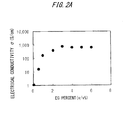
- FIG. 2A illustrates the electrical conductivity, ⁇ , of the PEDOT:PSS films plotted as a function of the EG concentration in the solution.
- FIG. 2B illustrates that the Seebeck coefficient at 303 K is not altered by the amount of EG in the solution. All samples had a Seebeck coefficient value of 24 ⁇ V/K.
- the dependence of the electrical conductivity and the Seebeck coefficient on the EG concentration can be attributed changes in the film morphology, because EG is only a co-solvent.
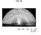
- FIGS. 3A and 3B illustrate the 2D GIWAXD patterns of the PEDOT:PSS films without and with addition of EG, respectively.
- the EG-added PEDOT : PSS films produced a stronger signal, suggesting the crystallinity is improved.
- the average crystal size calculated from the full width at half-maximum (FWHM) is increased from 1.9 nm (5-6 layers) to 2.5 nm (7-8 layers) by adding EG to the solution.
- the films with addition of EG shows more intense (020) reflections along the q z axis compared with the q xy axis, implying that PEDOT displayed face-on packing, and that the n-conjugated planes of the PEDOT crystal are more vertical with respect to the substrate.
- the improved crystallinity and preferred orientation of PEDOT are also confirmed by pole figures constructed from the 2D diffraction ( FIGS. 8A to 8C ).
- FIGS. 4A and 4B illustrate the 2D GISAXS patterns of the PEDOT: PSS films without and with addition of EG, respectively. Detailed line scans along the q z direction are illustrated in FIG. 4C .
- the improvement in the conductivity of PEDOT:PSS by the addition of EG is attributed to the increased crystal ordering and crystal size, which should increase the average carrier mobility in the film.
- the carrier scattering may be dominant at the interface between the PEDOT crystals, because the energy barrier at the interface should be larger.
- the scattering mechanisms at the interface may not be significantly affected by the crystal ordering and crystal size in this range; therefore the Seebeck coefficient is not changed significantly with addition of EG.
- the measurement of the Hall effect which provides the carrier mobility, addition density and effective mass of carriers in the PEDOT:PSS films, is attempted.
- the PEDOT:PSS solution (1 mL) is dropped on the surface of PDMS; after the solvent evaporated over several hours the PEDOT:PSS film is easily detached by bending the PDMS substrates slightly.
- the free-standing films are then annealed at 150 °C for 30 min in air.
- the thickness of the prepared films is from 30 to 40 ⁇ m, and the density is 1.5 g/cm 3 , which is calculated from the mass and volume, and is closing to the calculated value (1.45 g/cm 3 ).
- FIG. 5 illustrates the dependence of the thermal diffusivity of the PEDOT:PSS films on the EG concentration measured by temperature wave analysis. Interestingly, the thermal diffusivity is almost independent of the EG concentration, whereas the crystallinity and crystal ordering increased. All samples had thermal diffusivity values between 1.1 x 10 -7 and 1.4 x 10 -7 m 2 /s.
- the thermal conductivity measured by using flash analysis is 0.19 W/mK for the films without addition of EG, and 0.18 W/mK for the films with addition of 3 % EG.
- Carriers can only transport in the PEDOT domains of PEDOT:PSS films; therefore the electrical conductivity is strongly affected by the PEDOT crystallinity and ordering.
- the amount of PSS is much larger than that of PEDOT (1:2.5 w/w in PH1000), thus the PSS may be responsible for the thermal diffusivity and thermal conductivity. If the morphology of PSS did not change with the EG concentration, the thermal properties of the solid films should not change significantly.
- the amount of dopant is much larger than that of the host, which is very different from inorganic materials. Therefore, the thermal properties should depend on the insulating dopant more than on the conducting host.
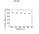
- FIG. 6A illustrates the thermoelectric properties of the PEDOT:PSS films with addition of 3 % EG.
- the electrical conductivity decreases from 830 S/cm at 303 K to 770 S/cm at 348 K.
- the decrease in the electrical conductivity with the increase in temperature might suggest that the EG-added PEDOT : PSS films behaved almost like a metal. This behavior is different from the behaviors of most organic semiconductors and low-conductivity PEDOT:PSS films and the behaviors of the electrical conductivity of the films without addition of EG increases with the temperature as illustrated in FIG. 10 .
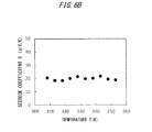
- FIG. 6B illustrates the temperature dependence of the Seebeck coefficient of the EG-added PEDOT:PSS films. The positive Seebeck coefficient indicates p-type conduction.
- the Seebeck coefficient is 20.5 ⁇ V/K at 303 K and 21.8 ⁇ V/K at 343 K, which suggests the Seebeck coefficient did not have significant temperature dependence in this temperature range.
- FIG. 7 illustrates the temperature dependence of the thermal properties.
- the thermal conductivity is measured as 0.17 W/mK at 303 K and 0.18 W/mK at 343 K.
- the calculated ZT at 303 K for the EG-added PEDOT: PSS films is 0.08.
- we must point out the ZT values are calculated from the in-plane electrical conductivity and cross-plane thermal conductivity. Therefore, the possibility remains that the PEDOT:PSS films display anisotropic thermal conductivity caused by the orientation and ordering of the PEDOT nanocrystals.
- the film thickness is measured by using a surface profilometer (Sloan Dektak 3, Veeco).
- the conductivity is measured with a four-probe conductivity test meter (MCP-T600, Mitsubishi Chemical Corporation), and the temperature is controlled with a hot plate.
- the Seebeck coefficient is measured with the homemade system illustrated in FIGS. 11A and 11B .
- the sample holder is heated in a mantle heater, and the temperature difference is achieved by using different metal blocks.
- the temperature difference and voltage are measured simultaneously by probing the pair of electrodes with a source meter.
- the thermal conductivity is measured by using a xenon flash analyzer (LFA 447 Nanoflash, Netzsch), and the thermal diffusivity is confirmed by using a temperature wave analyzer (ai-Phase Mobile, ai-Phase).
- X-ray scattering and diffraction are performed at room temperature using an X-ray diffractometer (D8 Discover, Bruker).
- FIG. 8A illustrates a 2D diffraction pattern of a PEDOT:PSS film without addition of EG.
- FIG. 8B illustrates a 2D diffraction pattern of a PEDOT:PSS film with addition of 3% EG.
- FIG. 8C illustrates pole figures constructed from the 2D diffraction patterns depicted in FIGS. 8A and 8B with respect to the polar angle.
- FIG. 9A illustrates a 2D SIXS pattern of a PEDOT:PSS film using transmission geometry without addition of EG.
- FIG. 9B illustrates a 2D SIXS pattern of a PEDOT:PSS film using transmission geometry with addition of 3% EG.
- FIG. 10 illustrates electrical conductivity, ⁇ , of a PEDOT:PSS films without addition of EG, plotted as a function of temperature.
- Clevios PH1000 is an aqueous solution in which PEDOT:PSS is dispersed, and it is considered that when solid PEDOT:PSS is obtained by simply drying the solution, the crystal structure of the obtained organic solid film may not be aligned sufficiently because water evaporates relatively quickly.
- ethylene glycol has a boiling point of 197.3 °C, which is twice as high as that of water, and it is considered that time may be ensured for the crystal structure to be aligned because ethylene glycol evaporates more slowly than water.
- Clevios PH1000 is an aqueous solution and made mostly of water, and Clevios PH1000 contains merely a few percent of PEDOT:PSS. In the present invention, it is advantageously determined whether 5 % is required or not and whether 3 % is enough or not regarding this "few percent".
- One of the features of the present invention is that a technique for precisely controlling the structures of organic semiconductor films is established and that the electrical conductivities, Zeebeck coefficients and the values of ZT may be increased. Further, in the present invention, a self-supported film (free-standing film) is obtained, and then the density is observed and the thermal conductivity is acquired on the basis of the measurement. In the present invention, it is featured that the large ZT values are actual measurement values.
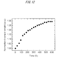
- FIG. 12 is a diagram illustrating the weight variation of PEDOT:PSS when PEDOT:PSS is kept in an atmosphere with relative humidity of 60 %. As illustrated in FIG. 12 , the weight of PEDOT:PSS increases by 30 % before the weight starts to vary. This is because the film of PEDOT:PSS contains water. It is noted that the thickness of the film increases by 30 % similarly when calculated.
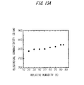
- FIGS. 13A and 13B illustrate measurement results of a thermoelectric material according to the present embodiment in a glove box with the relative humidity varied.
- FIG. 13A illustrates a measurement result of the electric conductivity of the thermoelectric material.
- FIG. 13B illustrates a measurement result of the thermal diffusivity of the thermoelectric material.
- the electric conductivity increases as the humidity increases, which leads to characteristic increase.
- the thermal diffusivity of the thermoelectric material does not change as the humidity varies, which does not lead to characteristic deterioration.
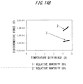
- FIGS. 14A and 14B illustrates graphs of ⁇ V/ ⁇ T of an organic thermoelectric material according to the present embodiment.
- a Seebeck coefficient S can be calculated based on the gradient of a graph.
- the graph indicated by “1” illustrates a variation in case of the relative humidity of 30 % (the amount of water is 9.114 g/m 3 ) and the temperature of 30 °C.
- the graph indicated by “2” illustrates a variation in case of the relative humidity of 50 % (the amount of water is 15.19 g/m 3 ) and the temperature of 30 °C. Since the reliability of the measurement can be determined based on the linearity of the graph, it can be said that the linearity of the graphs as illustrated FIGS.
- S 14 ⁇ V/K is obtained for the case of the relative humidity of 30 % (the temperature is 30 °C).
- the electric conductivity is set to 800 S/cm and the thermal diffusivity is set to 0.18 W/mk because the diffusivity coefficient is not varied based on the results in FIGS. 13A and 13B
- the maximum value of ZT is 0.33 with the relative humidity of 50 % and at the temperature of 40 °C. Therefore, the characteristic of the thermoelectric material according to the present embodiment can be increased by control of the amount of water. It is noted that the above values are illustrated in FIG. 14C .
- the Seebeck coefficient S and the electric conductivity ⁇ increase as the amount of water increases.
- the Seebeck coefficient increases as the temperature is raised. That is, the Seebeck coefficient at the temperature of 313K is larger than the Seebeck coefficient at the temperature of 303K.
- thermoelectric element and thermoelectric module the manufacturing of a thermoelectric element and thermoelectric module according to the present embodiment is described.
- the internal resistance, that is impedance, of the module as a whole is required to be low.
- the elements in the module can be connected in series to achieve a larger voltage.
- both the series connection and the parallel connection of the elements are employed to decrease the resistance in the thermoelectric module in the present embodiment.
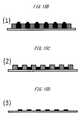
- FIGS. 15A to 15D includes schematic structural diagrams and a diagram of the manufacturing steps of a thermoelectric element according to the present embodiment. The longer a PEDOT:PSS element becomes, the larger the temperature difference becomes. But the resistance also becomes larger at the same time.
- the length, the width and thickness of one PEDOT:PSS element in the present embodiment is 40 mm, 2 mm and 30 ⁇ m, respectively.
- the resistance of the PEDOT:PSS element is equal to or less than 20 ⁇ .
- the height of PEDOT:PSS aqueous solution should be 5 mm to prepare a PEDOT:PSS element with the thickness of 30 ⁇ m. Therefore, PEDOT:PSS aqueous solution is poured into a mold form and the poured PEDOT:PSS aqueous solution is heated to evaporate water of the solution to obtain an organic thermoelectric film.
- PEDOT:PSS aqueous solution is poured into a mold form.
- (2) the PEDOT:PSS aqueous solution is heated at the temperature of 70 °C for 36 minutes to evaporate water of the solution to a certain degree.
- the mold form is removed and the PEDOT : PSS aqueous solution obtained by the process (2) is further heated at the temperature of 150 °C for 20 minutes to evaporate the solvent.
- an organic thermoelectric film can be obtained. It is noted that when the solvent is evaporated in the process (2) completely, the aqueous solution is fixed to the mold form so that the film is damaged. Therefore, the mold form is removed while the PEDOT: PSS aqueous solution is in a damp-dry condition.
- the processing temperature and the processing time of the manufacturing of the organic thermoelectric film according to the present embodiment as described above is a preferable condition in case of using a paper board as a substrate and stainless steel as the mold form. Therefore, the conditions depend on the material used for the substrate and the mold form and the processing time depends on the processing temperature.
- the condition of 150 °C and 20 minutes for the annealing as described above is a condition for manufacturing a single unit of PEDOT: PSS.
- the temperature is selected from the range from 125 to 200 °C according to the method employed for the manufacturing, and then the processing time is determined.
- the characteristic of the material can be improved by applying steam treatment to make the material to contain water and adjusting the amount of water included in the material.
- the atmospheric condition such as the humidity, the temperature, the retaining time etc. can be arbitrarily changed according to the shape of the material.
- a process including a sealing process is applied to the element and the substrate after the steam treatment for example.
- the process including the sealing process can inhibit the evaporation of water included in the element and the substrate.
- organic semiconductors generally may deteriorate in characteristics when the amount of water slightly varies.
- thermoelectric element since the water included in the thermoelectric element contributes a preferable improvement of the characteristics of the element, the variation of the amount of water included in the element is not a sensitive factor which changes the characteristics of the element. Therefore, a process such as wrapping which is a process of covering the element with a film using polyvinylidene chloride etc. and sealing which is a process of sealing the element using glass or a process of sealing the element using flexible material such as plastic can be employed to maintain the high characteristic of the thermoelectric element in the present embodiment.
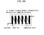
- FIGS. 16A and 16B illustrate examples of a module using elements in which the organic thermoelectric materials are connected in series according to the present embodiment.
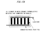
- FIGS. 17A and 17B illustrates examples of a module using elements in which the organic thermoelectric materials are connected in parallel according to the present embodiment. It is noted that “(a)” in FIG. 16B indicates “(a)” in FIG. 16A and “(b)” in FIG. 17B indicates “(b)” in FIG. 17A .
- an element as indicated by (a) in FIG. 16A in which organic thermoelectric materials are connected in series is manufactured at first. Next, a plurality of elements as indicated by (a) in FIG.
- an element as indicated by (b) in FIG. 17A in which organic thermoelectric materials are connected in parallel is manufactured at first.
- a plurality of elements as indicated by (b) in FIG. 17B in which organic thermoelectric materials are connected in parallel are manufactured and a unit as indicated by (d) in FIG. 17B in which the plurality of elements are connected in parallel is manufactured.
- the manufactured units are connected in parallel to manufacture a module using organic thermoelectric material according to the present embodiment as indicated by (f) in FIG. 17B .
- FIGS. 18A and 18B illustrate an example of an element manufactured using an organic thermoelectric material according to the present embodiment.
- PEDOT:PSS is applied onto a paper substrate at first as illustrated in FIG. 18A .
- eleven pieces of PEDOT:PSS with the length of 40 mm, the width of 2mm and the thickness of 30 ⁇ m are applied onto the paper substrate at equal intervals.
- each piece of the PEDOT:PSS applied onto the paper substrate is connected in series with conductive silver paste.
- FIG. 19 illustrates a manufactured module in which the thermoelectric element as described above is sandwiched with cupper plates which have a preferable thermal conductivity and each element is connected with each other.
- FIG. 20 illustrates the relations between the a temperature and the electric conductivity in the annealing in the manufacturing of a thermoelectric material according to the present embodiment.
- the electric conductivity of the manufactured thermoelectric material may decrease at the temperature below 125 °C as illustrated in FIG. 20 .
- PEDOT itself is decomposed at the temperature over 200 °C. Therefore, the preferable temperature for the annealing in the manufacturing of the thermoelectric material according to the present embodiment ranges from 125 °C to 200 °C.
- the processing time of the annealing can preferably be set to be more than 5 minutes in the present embodiment. It is noted that the processing time of the annealing can be set to be more than 30 minutes to ensure the evaporation of water and EG in the solution in the present embodiment.
- the annealing process is a process for manufacturing a film by evaporate the PEDOT:PSS solution including EG. And the annealing is required to progress slowly to arrange the film structure, namely to control the film structure. That is, when the PEDOT:PSS aqueous solution with addition of EG, the boiling point of which is higher than that of water, EG evaporate at the speed which is slower than that of water, and then the film structure is arranged in a preferable manner. As a result, the carrier mobility in the film can be increased and the electric conductivity can be increased.
- the annealing temperature is set too low, EG, the boiling point of which is 197 °C is difficult to be evaporated. Therefore, it is more preferable to set the annealing temperature to about 150 °C.
- the processing time of the annealing is preferably set to be within 12 hours.
- conductive polymer can be used instead of PEDOT in the present embodiment.
- the conductive polymer includes polyimide and polyaniline.
- tosylate (TOS), chlorine (Cl), perchloric acid (ClO 4 ) etc. can be used instead of PSS in the present embodiment.
- PSS which is stable and disperse preferably, is used in the present embodiment.
- a material with a high permittivity can be used instead of EG.
- Such alternative material includes ethanol, dimethyl sulfoxide (DMSO) and isopropanol, for example.
- DMSO dimethyl sulfoxide
- isopropanol can be used in terms of the permittivity, the boiling point of ethanol is 78 °C and the burning point of ethanol is 13 °C and the boiling point of isopropanol is 82.4 °C and the burning point of isopropanol is 11.7 °C. Therefore, ethanol and isopropanol cannot be expected to be used to control the film structure.
- DMSO can be expected to control the film structure as EG does.
- DMSO is required to be treated in consideration of the fact that DMSO has a characteristic of penetration of skin.
- EG is easier to be treated by a person conducting the annealing than the above materials since EG can be used as antifreeze for example.
- thermoelectric material can be applied to solar cells because not only light but also unused heat can be converted into electricity.
- thermoelectric material can be applied to devices attached to a human body including pacemakers and wrist watches. Further, the thermoelectric material can be applied to energy conservation fields in which low temperature waste heat below 200 °C is recovered as electricity.
Landscapes
- Engineering & Computer Science (AREA)
- Manufacturing & Machinery (AREA)
- Compositions Of Macromolecular Compounds (AREA)
- Processes Of Treating Macromolecular Substances (AREA)
Abstract
Description
- The embodiments described herein are related to an energy conservation technology field, especially to a field in which waste heat from thermoelectric materials is converted to electricity using organic semiconductors.
- A thermoelectric element (thermoelectric device) is an element in which both ends of two different types of metal or semiconductors are joined together and the temperature differences caused at the both ends are used to develop electromotive force, that is, Seebeck effect is used to convert thermal energy to electric energy. When a semiconductor is used to manufacture a thermoelectric element, a p-type semiconductor and an n-type semiconductor are combined. Organic materials are used as thermoelectric materials to manufacture a thermoelectric element. In conventional thermoelectric property characterizations of organic materials, TOS (para-toluenesulfonic acid ester) is used as dopant to PEDOT (Poly(3,4-ethylenedioxythiophene)).
- Related techniques are described in the following
non-patent document 1. - [Non-patent document 1] Bubnova, O.;Khan, Z. U.;Malti, A.;Braun, S.;Fahlman, M.;Berggren, M.;Crispin, X., Nat. Mater. 2011, 10, 429-433.
- Although the characteristics of TOS is that the composition control of TOS can be relatively easily achieved, the material itself is unstable and it cannot be easily achieved to eliminate metal ion which deteriorates the characteristics. Therefore, TOS is not applicable to the practical manufacturing of the thermoelectric element.
- In addition, Bi-Te system materials should be used as non-organic materials in consideration of waste heat recovery when the temperature of the waste heat of the thermoelectric materials is lower than 200 °C. In this case, the fact that the manufacturing cost increases because the materials are rare metal and the materials have toxic properties should be concerned. Further, since the materials are scarce elements and hard, namely fragile, use of large amounts of the materials is costly and maximizing the surface area of the thermoelectric elements will be difficult.
- According to the present invention, it is an object to provide an organic thermoelectric material and a thermoelectric module which is manufactured with stable materials, the cost of which can decrease and for which the production process can be easily established.
- In order to solve the above problems, a thermoelectric material disclosed herein is prepared by a manufacturing process including annealing at an annealing temperature from 125 °C to 200 °C and for an annealing time from 5 minutes to 12 hours applied to a material which includes conductive polymer, a substance selected from the group consisting of polystyrene sulfonate (PSS), tosylate (TOS), chloride and perchlorate and a substance as solvent selected from the group consisting of ethylene glycol, ethanol, dimethyl sulfoxide and isopropanol. With the annealing process employed, a thermoelectric material having a preferable crystal orientation can be manufactured without a complicated process.
- In addition, the conductive polymer is Poly(3,4-ethylenedioxythiophene) (PEDOT). Further, the solvent is ethylene glycol with the additive amount of equal to or more than 3 % by weight. Moreover, the annealing temperature is about 150 °C. And the annealing time is at least equal to more than 30 minutes.
- Additionally, the manufacturing process includes a process of making the material contain water in the embodiments. In addition, a process of sealing the material is performed after the process of making the material contain water in the embodiments. As a result, a high figure of merit of the thermoelectric material manufactured in the embodiments can be achieved while the water evaporation from the thermoelectric material can be preferably inhibited.
- Further, a thermoelectric module is manufactured by using a p-type or an n-type of the thermoelectric material in the embodiments. Alternatively, a thermoelectric module is manufactured by combining a p-type and an n-type of the thermoelectric material in the embodiments. As a result, the structure of the thermoelectric material can be flexibly changed to manufacture the thermoelectric module which can achieve a preferable voltage for practical use.
- Furthermore, the thermoelectric module is manufactured by connecting a plurality of units in series in which a plurality of elements are connected in parallel, the element being formed by connecting the thermoelectric materials in series. Alternatively, the thermoelectric module is manufactured by connecting a plurality of units in parallel in which a plurality of elements are connected in series, the element being formed by connecting the thermoelectric materials in parallel.
- It has been reported that a thermoelectric material using organic semiconductors has the performance index (ZT) is equal to or lower than 0.1. Aside from this, only a thermoelectric material having a ZT value of 0.25 has been reported. On the other hand, a thermoelectric material using an organic semiconductor with ZT being 0.33 can be obtained according to the present invention. It is noted that ZT should preferably be 1 for practical use. In addition, a thermoelectric material can be formed into a thin material or into any shapes since the thermoelectric material is water-soluble. Further, a thermoelectric material can be formed on an inexpensive flexible sheet such as a paper sheet.
-
-
FIG. 1 is a diagram schematically illustrating a thermoelectric element using a thermoelectric material according to an embodiment; -
FIG. 2A is a graph of electrical conductivity σ plotted as a function of the amount of EG according to an embodiment; -
FIG. 2B is a graph of Seebeck coefficient S plotted as a function of the amount of EG according to an embodiment; -
FIG. 3A illustrates a two dimensional GIWAXD pattern of a PEDOT:PSS thin film without addition of EG according to an embodiment; -
FIG. 3B illustrates a two dimensional GIWAXD pattern of a PEDOT:PSS thin film with addition of 3% EG according to an embodiment; -
FIG. 4A illustrates a two dimensional GISAXS pattern of a PEDOT:PSS thin film without addition of EG according to an embodiment; -
FIG. 4B illustrates a two dimensional GISAXS pattern of a PEDOT:PSS thin film with addition of 3% EG according to an embodiment; -
FIG. 4C illustrates a result of detailed line scans along the qz direction according to an embodiment; -
FIG. 5 illustrates thermal diffusivityplottedas a function of the amount of EG in solution according to an embodiment, and an as-prepared free-standing film is depicted in the insert; -
FIG. 6A illustrates electrical conductivity σ of a PEDOT: PSS film with addition of 3% EG plotted as a function of temperature according to an embodiment; -
FIG. 6B illustrates Seebeck coefficient S of the PEDOT: PSS film with addition of 3% EG plotted as a function of temperature according to an embodiment; -
FIG. 7 illustrates relations between temperature and thermal conductivity, temperature and thermal diffusivity, and temperature and thermal capacity according to an embodiment; -
FIG. 8A illustrates a 2D diffraction pattern of a PEDOT: PSS film without addition of EG according to an embodiment; -
FIG. 8B illustrates a 2D diffraction pattern of a PEDOT: PSS film with addition of 3% EG according to an embodiment; -
FIG. 8C illustrates pole figures constructed from the 2D diffraction patterns depicted inFIGS. 8A and8B with respect to the polar angle; -
FIG. 9A illustrates a 2D SIXS pattern of a PEDOT:PSS film using transmission geometry without addition of EG according to an embodiment; -
FIG. 9B illustrates a 2D SIXS pattern of a PEDOT:PSS film using transmission geometry with addition of 3% EG according to an embodiment; -
FIG. 10 illustrates electrical conductivity σ of a PEDOT: PSS film without addition of EG plotted as a function of temperature according to an embodiment; -
FIG. 11A illustrates a homemade Seebeck coefficient measurement system according to an embodiment; -
FIG. 11B illustrates a sample holder in the homemade Seebeck coefficient measurement system as illustrated inFIG. 11A ; -
FIG. 12 illustrates variations in weight of a PEDOT:PSS when a thermoelectric material according to an embodiment retained in an atmosphere of 298 K and a relative humidity of 60%; -
FIG. 13A illustrates relations between relative humidity and electrical conductivity according to a thermoelectric material according to an embodiment; -
FIG. 13B illustrates relations between relative humidity and thermal diffusivity according to a thermoelectric material according to an embodiment; -
FIG. 14A illustrates a graph of ΔV/ΔT at 303 K of a thermoelectric material according to an embodiment, where the line indicated by "1" corresponds to the relative humidity of 30% and the line indicated by "2" corresponds to the relative humidity of 50%; -
FIG. 14B illustrates a graph of ΔV/ΔT at 313 K of a thermoelectric material according to an embodiment, where the line indicated by "1" corresponds to the relative humidity of 30% and the line indicated by "2" corresponds to the relative humidity of 50%; -
FIG. 14C illustrates a table of the figure of merit ZT calculated using Seebeck coefficients obtained from the gradients as illustrated by the graphs inFIGS. 14A and14B , thermal conductivity and electrical conductivity; -
FIG. 15A illustrates an example of a method of manufacturing an organic thermoelectric film according to an embodiment; -
FIG. 15B illustrates an example of a method of manufacturing an organic thermoelectric film according to an embodiment; -
FIG. 15C illustrates an example of a method of manufacturing an organic thermoelectric film according to an embodiment; -
FIG. 15D illustrates an example of a method of manufacturing an organic thermoelectric film according to an embodiment; -
FIG. 16A schematically illustrates a configuration of a thermoelectric module according to an embodiment; -
FIG. 16B schematically illustrates a configuration of a thermoelectric module according to an embodiment; -
FIG. 17A schematically illustrates a configuration of a thermoelectric module according to an embodiment; -
FIG. 17B schematically illustrates a configuration of a thermoelectric module according to an embodiment; -
FIG. 18A illustrates an example of a method of manufacturing an thermoelectric element according to an embodiment; -
FIG. 18B illustrates an example of a method of manufacturing an thermoelectric element according to an embodiment; -
FIG. 19 illustrates an example of a method of manufacturing an thermoelectric module according to an embodiment; and -
FIG. 20 illustrates relations between heat process temperature and electrical conductivity of a thermoelectric material according to an embodiment. - Embodiments according to the present invention are described below with reference to the drawings. It is to be understood that both the foregoing general description and the following detailed description are exemplary and explanatory and are not restrictive of the invention, as claimed.
- A thermoelectric material of which the electrical conductivity is high and the Seebeck coefficient is not decreased can be manufactured by nanostructure control to increase the carrier mobility without increasing the carrier density. In addition, the thermoelectric material can be manufactured on a flexible sheet such as a paper and the thermal electromotive force of 0.5 mV is confirmed by measurement. And the voltage which can be obtained from the arrangement according to an embodiment can be increased by simply increasing the number of materials manufactured on the flexible sheet.
-
FIG. 1 is a diagram schematically illustrating a thermoelectric element manufactured using a thermoelectric material according to an embodiment. A material with a figure of merit of 2T=0.08 (at room temperature), which is applicable as an organic thermoelectric material, can be obtained in the embodiment by using mainly PEDOT : PSS, which is known as an organic conducting material, and controlling the structure etc. of the material to improve the characteristics as a thermoelectric material. - As illustrated in
FIG.1 , the thermoelectric materials according to the present embodiment can be connected in series by conductive wires or conductive paste to increase the amount of electric output due to temperature difference. Additionally, both the p-type region and the n-type region are not necessarily connected with each other in the thermoelectric material according to the present embodiment. - Since the temperature difference canbe obtained along the longitudinal direction of the material and the low thermal conductivity, which is characteristic of organic material, can achieve a temperature difference larger than that of a conventional material, the waste heat can be exploited to the full.
- Further, a thin, lightweight and flexible thermoelectric element can be manufactured by instillation of the material onto the flexible sheet or by attachment of a freestanding film onto the flexible sheet. In addition, since the thermoelectric element can be printed on an inexpensive material such as a paper, the thermoelectric element can be manufactured at a cost lower than that of a conventional thermoelectric element.
- A thermoelectric material is generally manufactured as a module by connecting the p-type region and the n-type region by a conductive material to increase the voltage. However, a thermoelectric element by which the voltage can be increased can be manufactured in the present embodiment by merely connecting one of the p-type region and the n-type region with a conductive material. This type of manufacturing thermoelectric materials, that is, connecting one of the p-type region and the n-type region with a conductive material, is novel. It is noted that the shape of the organic thermoelectric film and the shape of the conductive material can be arbitrarily designed at the higher temperature side and at the lower temperature side. That is, the shapes can be either a linear profile or a curve profile. In essence, the shapes can be any shape as long as the temperature difference can be achieved. The thermoelectric material can be manufactured to include curve sections. Alternatively, the thermoelectric material can be bent after production. Therefore, the conductive material used in the present embodiment can be any materials as long as the electric conductivity is ensured. That is, the conductive material can be a metal wire and conductive paste etc. Any restrictions are not imposed on the metal component of the conductive material. Therefore, gold, cupper, platinum and silver etc. can be used as the conductive material.
- Moreover, any flexible sheet can be used for manufacturing the organic thermoelectric material according to the present embodiment as long as the electrical insulation can be ensured. That is, a paper and a plastic film can be used in the present embodiment. However, a process for providing a hydrophilic property for the surface of the material is performed depending on the type of material when a plastic film is used in the present embodiment, since PEDOT:PSS solution is dropped onto the surface. It is noted that the method of providing a hydrophilic property for the surface of the material can be arbitrarily selected. For example, applying masking to the surface and exposing the surface to ultraviolet light can form a hydroxyl on the surface to provide the surface with a hydrophilic property since oxygen is converted into ozone in the air. With this method, a thermoelectric material can be formed in any shape in the present embodiment.
- We report that highly ordered poly(3,4-ethylenedioxythiophene):poly(styrenesulfonate) (PEDOT: PSS) films displayed a high thermoelectric figure of merit at room temperature. Grazing-incidence wide angle X-ray diffraction (GIWAXD) and grazing-incidence small-angle X-ray scattering (GISAXS) illustrate that adding ethylene glycol (EG) to the PEDOT:PSS solution improved the crystallinity of PEDOT and the ordering of the PEDOT nanocrystals in the solid films. The highly ordered PEDOT : PSS films had an electrical conductivity of 830 S/cm, a Seebeck coefficient of 44 µk/V, and a thermal conductivity of 0.18 W/mK, resulting in a figure of merit of 0.27 at 303 K. Our results suggest that these organic semiconducting materials could be very promising for low-temperature thermoelectric elements.
- Thermoelectric elements, which can be used for the direct conversion of heat energy to electricity, have drawn intense interest as promising candidates for harvesting waste heat and solar thermal energy. The most important parameter for evaluating the performance of the thermoelectric materials is the figure of merit (ZT), which is defined as

where S is the Seebeck coefficient, σ is the electrical conductivity, κ is the thermal conductivity, and T is the temperature. Pioneering studies of thermoelectric materials mainly focused on inorganic semiconductors, such as bismuth-telluride (Bi-Te) alloys, magnesium-silicon (Mg-Si) alloys, and metal oxides. Most of these materials work at temperatures higher than 200 °C; the best known low-temperature thermoelectric material is Bi2Te3, which has a room temperature ZT greater than 1. However, waste heat and solar-thermal energy are usually at temperatures lower than 150 °C. The efficiency of thermal power conversion at low temperatures is low because of the small temperature difference. Therefore, to harvest the huge amount of thermal energy available at low temperatures, large-area thermoelectric elements are necessary. However, Te is a rare metal; it is expensive and not environmental friendly, and is thus not suitable for large-area thermoelectric elements. - Unlike their inorganic counterparts, organic semiconductors have not been thoroughly investigated, because of their relatively low electrical conductivity and Seebeck coefficient. Recent advances in organic electronics for elements such as organic solar cells and transistors have improved the physical and chemical properties of organic semiconductors. They can now be tuned over a fairly large range, which may make them suitable for thermoelectric elements. Moreover, organic semiconductors generally have a low intrinsic thermal conductivity, which could produce organic thermoelectric elements with high conversion efficiencies.
- Early studies on organic thermoelectrics mainly focused on polyaniline, polypyrrole, and polythiophene. The stable power factor (P = S2σ) for these materials is less than 10 µW/mK2, and ZT is on the order of 10-3. Leclerc et al. have reported that polycarbazole may be a promising candidate for thermoelectric applications, because of its high electrical conductivity and Seebeck coefficient. Hybrid materials, such as conducting polymers and quantum dots, conducting polymers and carbon nanotubes, and metal complexes, have also attracted much attention because they have high Seebeck coefficients and are simple to process. Very recently, Crispin et al. reported that the de-doping of highly conductivity poly(3,4-ethylenedioxythiophene):tosylate (PEDOT:tos) with tetrakis(dimethylamino)ethylene (TDAE) can produce a remarkable ZT value of 0.25, and a power factor greater than 300 µW/mK2, mainly because of the high Seebeck coefficient (>200 µV/K). This indicates that the performance of organic thermoelectrics could approach that of their inorganic counterparts. Poly(3,4-ethylenedioxythiophene):poly(styrenesulfonate) (PEDOT:PSS) is the most studiedconductingpolymer systembecause of its potential use as a transparent electrode. Adding a second solvent, such as ethylene glycol (EG) or dimethyl sulfoxide (DMSO), to an aqueous dispersion of PEDOT: PSS can dramatically enhance its electrical conductivity. Numerous studies have been published on optimizing the process conditions to improve electrical conductivity of PEDOT:PSS, and on understanding the underlying mechanisms. However, there are relatively few studies on the thermoelectric properties of these highly conductive PEDOT:PSS systems. Katz et al. have reported power factors of 47 µW/mK2 for highly conductive PEDOT:PSS, although the Seebeck coefficient decreased significantly as the electrical conductivity increased, and the thermal conductivity is not reported.
- Here, we report the thermoelectric properties of commercial Clevios PH1000 PEDOT:PSS with addition of a second solvent, EG. The addition of ethylene glycol significantly increased the electrical conductivity of PEDOT:PSS without decreasing the Seebeck coefficient. The film morphology is examined by grazing-incidence wide angle X-ray diffraction (GIWAXD) and grazingincidence small-angle X-ray scattering (GISAXS) (Bruker D8 discover X-ray diffractometer) in order to explain the results. Free-standing PEDOT:PSS films with addition of different concentrations of EG are prepared, and their thermal properties are examined by using flash analysis and temperature wave analysis methods.
- All films used to measure the electrical conductivity and Seebeck coefficients are prepared on glass substrates by drop casting. The PEDOT:PSS solution (400 µL) with or without addition of EG is dropped onto a 2 x 2 cm glass substrate, and the solvent is slowly evaporated over several hours. The film is annealed at 150 °C for 30 min in air. The thickness of the film is measured by using a surface profiler, and is about 8 µm. The slow initial evaporation of the solvent is critical in forming a smooth film. The electrical conductivity is measured by using a conventional four-probe method.
FIG. 2A illustrates the electrical conductivity, σ, of the PEDOT:PSS films plotted as a function of the EG concentration in the solution. As the EG concentration increased to 3 %, σ increased and then decreased slightly at higher concentrations. These observations are consistent with previous reported results. The Seebeck coefficient is measured for temperature differences between 1 and 8 °C. The slopes of the plots of ΔV versus ΔT gave values of S; more than 30 points are used for the curve fitting.FIG. 2B illustrates that the Seebeck coefficient at 303 K is not altered by the amount of EG in the solution. All samples had a Seebeck coefficient value of 24 µV/K. The dependence of the electrical conductivity and the Seebeck coefficient on the EG concentration can be attributed changes in the film morphology, because EG is only a co-solvent. To understand the effect of EG addition on the film morphology, GIWAXD and GISAXS studies are carried out. -
FIGS. 3A and3B illustrate the 2D GIWAXD patterns of the PEDOT:PSS films without and with addition of EG, respectively. Clear diffractions at q = 1.28 Å-1 and q = 1.85 Å-1 suggested that both films are crystalline. The diffraction at q = 1.28 Å-1 is assigned to randomly distributed PSS, and the well-defined diffraction at q = 1.85 Å-1 arose from the (020) reflection of PEDOT crystals (n-n interchain stacking). The EG-added PEDOT : PSS films produced a stronger signal, suggesting the crystallinity is improved. The average crystal size calculated from the full width at half-maximum (FWHM) is increased from 1.9 nm (5-6 layers) to 2.5 nm (7-8 layers) by adding EG to the solution. The films with addition of EG shows more intense (020) reflections along the qz axis compared with the qxy axis, implying that PEDOT displayed face-on packing, and that the n-conjugated planes of the PEDOT crystal are more vertical with respect to the substrate. The improved crystallinity and preferred orientation of PEDOT are also confirmed by pole figures constructed from the 2D diffraction (FIGS. 8A to 8C ). - The mesoscopic structure of the PEDOT: PSS films over a large surface area is determined by GISAXS.
FIGS. 4A and4B illustrate the 2D GISAXS patterns of the PEDOT: PSS films without and with addition of EG, respectively. Detailed line scans along the qz direction are illustrated inFIG. 4C . The GISAXS pattern for the film without addition of EG shows an out-of-plane scattering peak at qz = 0.24 Å-1 and a second-order scattering peak at qz = 0.49 Å-1. The EG-added film pattern, the scattering peak at qz = 0.24 Å-1 is sharper, and a third-order peak at a q value three-fold higher than the first is observed. This suggests the addition of EG increased the order of the PEDOT nanocrystal; these nanocrystals should form a layered structure. No obvious peaks are detected in the in-plane direction, implying the structure of the PEDOT nanocrystals are disordered along the qxy direction. This is further supported by the SAXS patterns using transmission geometry (FIGS. 9A and9B ), in which no clear diffraction is observed. - The improvement in the conductivity of PEDOT:PSS by the addition of EG is attributed to the increased crystal ordering and crystal size, which should increase the average carrier mobility in the film. However, the carrier scattering may be dominant at the interface between the PEDOT crystals, because the energy barrier at the interface should be larger. The scattering mechanisms at the interface may not be significantly affected by the crystal ordering and crystal size in this range; therefore the Seebeck coefficient is not changed significantly with addition of EG. To obtain direct evidence of this, the measurement of the Hall effect, which provides the carrier mobility, addition density and effective mass of carriers in the PEDOT:PSS films, is attempted. However, measuring the Hall effect for PEDOT:PSS is very challenging, probably because of the carrier transfer mechanism, the Seebeck effect during current flow, the mobile ions in PEDOT:PSS, and the effect of the small amount of water in the films. However, we are confident that the effect of EG on the electrical conductivity and Seebeck coefficient can be explained by the changes in morphology.
- Flash analysis and temperature wave analysis experiments are conducted to estimate the thermal properties of PEDOT:PSS. In both experiments, a large area (>1 x 1 cm) of highly dense, free-standing film at least 30 µm thick, is critical for reliable measurements. Initially, we attempted to float off the drop casted films using solvents. However, the PEDOT:PSS films are not self-supported on solvents and are very difficult to handle. Low surface energy materials are successfully employed as substrates instead. Cross-linked polydimethylsiloxane (PDMS) is used as the substrate because it displays both hydrophobic and oleophilic properties. The PEDOT:PSS solution (1 mL) is dropped on the surface of PDMS; after the solvent evaporated over several hours the PEDOT:PSS film is easily detached by bending the PDMS substrates slightly. The free-standing films are then annealed at 150 °C for 30 min in air. The thickness of the prepared films is from 30 to 40 µm, and the density is 1.5 g/cm3, which is calculated from the mass and volume, and is closing to the calculated value (1.45 g/cm3). This suggests the as-prepared free-standing PEDOT:PISS films had a dense structure, which is important for determining the intrinsic thermal properties by using temperature wave analysis and flash analysis techniques.
-
FIG. 5 illustrates the dependence of the thermal diffusivity of the PEDOT:PSS films on the EG concentration measured by temperature wave analysis. Interestingly, the thermal diffusivity is almost independent of the EG concentration, whereas the crystallinity and crystal ordering increased. All samples had thermal diffusivity values between 1.1 x 10⁻⁷ and 1.4 x 10⁻⁷ m2/s. The thermal conductivity measured by using flash analysis is 0.19 W/mK for the films without addition of EG, and 0.18 W/mK for the films with addition of 3 % EG. These results are very different from those of most inorganic thermoelectric materials. This can be explained by the coexistence of conducting PEDOT and insulating PSS. Carriers can only transport in the PEDOT domains of PEDOT:PSS films; therefore the electrical conductivity is strongly affected by the PEDOT crystallinity and ordering. However, the amount of PSS is much larger than that of PEDOT (1:2.5 w/w in PH1000), thus the PSS may be responsible for the thermal diffusivity and thermal conductivity. If the morphology of PSS did not change with the EG concentration, the thermal properties of the solid films should not change significantly. In most highly conductivity PEDOT systems, the amount of dopant is much larger than that of the host, which is very different from inorganic materials. Therefore, the thermal properties should depend on the insulating dopant more than on the conducting host. -
FIG. 6A illustrates the thermoelectric properties of the PEDOT:PSS films with addition of 3 % EG. The electrical conductivity decreases from 830 S/cm at 303 K to 770 S/cm at 348 K. The decrease in the electrical conductivity with the increase in temperature might suggest that the EG-added PEDOT : PSS films behaved almost like a metal. This behavior is different from the behaviors of most organic semiconductors and low-conductivity PEDOT:PSS films and the behaviors of the electrical conductivity of the films without addition of EG increases with the temperature as illustrated inFIG. 10 .FIG. 6B illustrates the temperature dependence of the Seebeck coefficient of the EG-added PEDOT:PSS films. The positive Seebeck coefficient indicates p-type conduction. The Seebeck coefficient is 20.5 µV/K at 303 K and 21.8 µV/K at 343 K, which suggests the Seebeck coefficient did not have significant temperature dependence in this temperature range.FIG. 7 illustrates the temperature dependence of the thermal properties. The thermal conductivity is measured as 0.17 W/mK at 303 K and 0.18 W/mK at 343 K. The calculated ZT at 303 K for the EG-added PEDOT: PSS films is 0.08. Finally, we must point out the ZT values are calculated from the in-plane electrical conductivity and cross-plane thermal conductivity. Therefore, the possibility remains that the PEDOT:PSS films display anisotropic thermal conductivity caused by the orientation and ordering of the PEDOT nanocrystals. However, we think that the effect of the PEDOT nanocrystals is small, because the thermal conductivity should mainly be determined by the PSS. Our hypothesis is supported by pioneering studies on the PEDOT:tos systems which used the 3ω-technique to illustrate that heat propagation is almost isotropic. We are currently measuring the in-plane thermal conductivity by flash analysis. - In conclusion, the addition of EG to commercially available PEDOT: PSS can increase both the crystal size of PEDOT and the crystal ordering of the film. As a result, the electrical conductivity could be increased to 830 S/cm, whereas the Seebeck coefficient is not decreased. A low thermal conductivity of 0.18 W/mK is confirmed by flash analysis of a dense freestanding sample. Our results suggest that organic semiconducting materials are promising for low-temperature thermoelectric element applications.
- Chemicals. Poly(3,4-ethylenedioxythiophene):poly(styrenesulfonate) (PEDOT:PSS; Clevios PH1000) purchased from H.C. Starck and ethylene glycol (EG, >99.5 %) purchased from TCI Chemicals are used.
- Film Preparation. For the conductivity and Seebeck coefficient measurements, all films are prepared on glass substrates by drop casting. The PEDOT:PSS solution (400 µL) is applied to a 2 x 2 cm glass substrate, and the solvent is slowly evaporated over several hours. The film is annealed at 150 °C for 30 min, and the film thickness is equal to or less than 8 µm. The free standing films are prepared on polydimethylsiloxane (PDMS). The PEDOT:PSS solution (1 mL) is dropped on the surface of PDMS. The solvent is evaporated over several hours, and the PEDOT:PSS film is easily detached by bending the PDMS substrates slightly. The thickness of the prepared films is 30-40 µm.
- Characterization. The film thickness is measured by using a surface profilometer (
Sloan Dektak 3, Veeco). The conductivity is measured with a four-probe conductivity test meter (MCP-T600, Mitsubishi Chemical Corporation), and the temperature is controlled with a hot plate. The Seebeck coefficient is measured with the homemade system illustrated inFIGS. 11A and11B . The sample holder is heated in a mantle heater, and the temperature difference is achieved by using different metal blocks. The temperature difference and voltage are measured simultaneously by probing the pair of electrodes with a source meter. The thermal conductivity is measured by using a xenon flash analyzer (LFA 447 Nanoflash, Netzsch), and the thermal diffusivity is confirmed by using a temperature wave analyzer (ai-Phase Mobile, ai-Phase). X-ray scattering and diffraction are performed at room temperature using an X-ray diffractometer (D8 Discover, Bruker). -
FIG. 8A illustrates a 2D diffraction pattern of a PEDOT:PSS film without addition of EG.FIG. 8B illustrates a 2D diffraction pattern of a PEDOT:PSS film with addition of 3% EG.FIG. 8C illustrates pole figures constructed from the 2D diffraction patterns depicted inFIGS. 8A and8B with respect to the polar angle. -
FIG. 9A illustrates a 2D SIXS pattern of a PEDOT:PSS film using transmission geometry without addition of EG.FIG. 9B illustrates a 2D SIXS pattern of a PEDOT:PSS film using transmission geometry with addition of 3% EG. -
FIG. 10 illustrates electrical conductivity, σ, of a PEDOT:PSS films without addition of EG, plotted as a function of temperature. -
FIG. 11A illustrates a homemade Seebeck coefficient measurement system.FIG. 11B illustrates a sample holder thereof. - As described above, a thermoelectric material is obtained by a simple process which only includes an annealing at 150 °C for 30 min. In addition, the structures of the obtained organic films are examined by X-ray diffraction to find that the treatment at 150 °C for 30 min is appropriate for obtaining structures having crystal orientations. A feature of the present invention is that a simple process as described above may be employed. Further, there have been no examples that the effects of ethylene glycol are precisely examined from the structural examination by X-ray diffraction.
- Essentially, although it is known that the electrical conductivity is improved when ethylene glycol is introduced, the reasons are not apparent. Clevios PH1000 is an aqueous solution in which PEDOT:PSS is dispersed, and it is considered that when solid PEDOT:PSS is obtained by simply drying the solution, the crystal structure of the obtained organic solid film may not be aligned sufficiently because water evaporates relatively quickly. On the other hand, ethylene glycol has a boiling point of 197.3 °C, which is twice as high as that of water, and it is considered that time may be ensured for the crystal structure to be aligned because ethylene glycol evaporates more slowly than water. Additionally, as described above, the structures of the obtained films are examined by X-ray diffraction to find that there are some correlations between the crystal orientations and the electrical conductivity. Moreover, it also found that sufficient results may be obtained with the additive amount of ethylene glycol equal to or higher than 3% rather than 5 %. Clevios PH1000 is an aqueous solution and made mostly of water, and Clevios PH1000 contains merely a few percent of PEDOT:PSS. In the present invention, it is advantageously determined whether 5 % is required or not and whether 3 % is enough or not regarding this "few percent".
- One of the features of the present invention is that a technique for precisely controlling the structures of organic semiconductor films is established and that the electrical conductivities, Zeebeck coefficients and the values of ZT may be increased. Further, in the present invention, a self-supported film (free-standing film) is obtained, and then the density is observed and the thermal conductivity is acquired on the basis of the measurement. In the present invention, it is featured that the large ZT values are actual measurement values.
- Next, it is understood from
FIG. 12 that water may change the characteristics of organic thermoelectric materials.FIG. 12 is a diagram illustrating the weight variation of PEDOT:PSS when PEDOT:PSS is kept in an atmosphere with relative humidity of 60 %. As illustrated inFIG. 12 , the weight of PEDOT:PSS increases by 30 % before the weight starts to vary. This is because the film of PEDOT:PSS contains water. It is noted that the thickness of the film increases by 30 % similarly when calculated. -
FIGS. 13A and13B illustrate measurement results of a thermoelectric material according to the present embodiment in a glove box with the relative humidity varied.FIG. 13A illustrates a measurement result of the electric conductivity of the thermoelectric material. AndFIG. 13B illustrates a measurement result of the thermal diffusivity of the thermoelectric material. As illustrated inFIG. 13A , the electric conductivity increases as the humidity increases, which leads to characteristic increase. In addition, as illustrated inFIG. 13B , the thermal diffusivity of the thermoelectric material does not change as the humidity varies, which does not lead to characteristic deterioration. -
FIGS. 14A and14B illustrates graphs of ΔV/ΔT of an organic thermoelectric material according to the present embodiment. A Seebeck coefficient S can be calculated based on the gradient of a graph. InFIGS. 14A and14B , the graph indicated by "1" illustrates a variation in case of the relative humidity of 30 % (the amount of water is 9.114 g/m3) and the temperature of 30 °C. In addition the graph indicated by "2" illustrates a variation in case of the relative humidity of 50 % (the amount of water is 15.19 g/m3) and the temperature of 30 °C. Since the reliability of the measurement can be determined based on the linearity of the graph, it can be said that the linearity of the graphs as illustratedFIGS. 14A and14B is preferable.FIG. 14A illustrates a comparison result at the temperature T = 30 °C (303K) since a wide temperature range can be set so that the variation can be easily recognized. When Seebeck coefficients are calculated based on each graph, S = 14 µV/K is obtained for the case of the relative humidity of 30 % (the temperature is 30 °C). In addition, S = 33 µV/K is obtained for the case of the relative humidity of 50 % (the temperature is 30 °C) and is larger than the Seebeck coefficient for the case of the relative humidity of 30 % (the temperature is 30 °C).FIG. 14B illustrates a comparison result at the temperature T = 40 °C (313K). S = 15.6 µV/K is obtained for the case of the relative humidity of 50 % (the temperature is 40 °C). In addition, S = 48.4 µV/K is obtained for the case of the relative humidity of 50 % (the temperature is 40 °C). When the electric conductivity is set to 800 S/cm and the thermal diffusivity is set to 0.18 W/mk because the diffusivity coefficient is not varied based on the results inFIGS. 13A and13B , the maximum value of ZT is 0.33 with the relative humidity of 50 % and at the temperature of 40 °C. Therefore, the characteristic of the thermoelectric material according to the present embodiment can be increased by control of the amount of water. It is noted that the above values are illustrated inFIG. 14C . - From the measurements as illustrated in
FIGS. 14A to 14C , the Seebeck coefficient S and the electric conductivity σ increase as the amount of water increases. In addition, the Seebeck coefficient increases as the temperature is raised. That is, the Seebeck coefficient at the temperature of 313K is larger than the Seebeck coefficient at the temperature of 303K. Although κ cannot measured directly, it can be assumed that the value of ZT also increases as the amount of water increases since κ = (thermal diffusivity coefficient) x (specific heat) x (density) and the thermal diffusivity coefficient does not vary as described above in the present embodiment. - Next, the manufacturing of a thermoelectric element and thermoelectric module according to the present embodiment is described. In the manufacturing the thermoelectric module, the internal resistance, that is impedance, of the module as a whole is required to be low. In addition, the elements in the module can be connected in series to achieve a larger voltage. However, when the elements are connected in series and one of the elements connected is damaged, the module cannot be used practically. Therefore, both the series connection and the parallel connection of the elements are employed to decrease the resistance in the thermoelectric module in the present embodiment.
FIGS. 15A to 15D includes schematic structural diagrams and a diagram of the manufacturing steps of a thermoelectric element according to the present embodiment. The longer a PEDOT:PSS element becomes, the larger the temperature difference becomes. But the resistance also becomes larger at the same time. In addition, the larger the thickness of the element becomes, the smaller the resistance becomes. For example, the length, the width and thickness of one PEDOT:PSS element in the present embodiment is 40 mm, 2 mm and 30 µm, respectively. And, the resistance of the PEDOT:PSS element is equal to or less than 20 Ω. it is noted that the height of PEDOT:PSS aqueous solution should be 5 mm to prepare a PEDOT:PSS element with the thickness of 30 µm. Therefore, PEDOT:PSS aqueous solution is poured into a mold form and the poured PEDOT:PSS aqueous solution is heated to evaporate water of the solution to obtain an organic thermoelectric film. - As illustrated in
FIGS. 15B to 15D , (1) PEDOT:PSS aqueous solution is poured into a mold form. Next, (2) the PEDOT:PSS aqueous solution is heated at the temperature of 70 °C for 36 minutes to evaporate water of the solution to a certain degree. Next, the mold form is removed and the PEDOT : PSS aqueous solution obtained by the process (2) is further heated at the temperature of 150 °C for 20 minutes to evaporate the solvent. As a result an organic thermoelectric film can be obtained. It is noted that when the solvent is evaporated in the process (2) completely, the aqueous solution is fixed to the mold form so that the film is damaged. Therefore, the mold form is removed while the PEDOT: PSS aqueous solution is in a damp-dry condition. - The processing temperature and the processing time of the manufacturing of the organic thermoelectric film according to the present embodiment as described above is a preferable condition in case of using a paper board as a substrate and stainless steel as the mold form. Therefore, the conditions depend on the material used for the substrate and the mold form and the processing time depends on the processing temperature. The condition of 150 °C and 20 minutes for the annealing as described above is a condition for manufacturing a single unit of PEDOT: PSS. When the thermoelectric elementis manufactured, the temperature is selected from the range from 125 to 200 °C according to the method employed for the manufacturing, and then the processing time is determined.
- Further, when the material (PEDOT:PSS) is manufactured on the substrate including a paper, the characteristic of the material can be improved by applying steam treatment to make the material to contain water and adjusting the amount of water included in the material. The atmospheric condition such as the humidity, the temperature, the retaining time etc. can be arbitrarily changed according to the shape of the material. And a process including a sealing process is applied to the element and the substrate after the steam treatment for example. The process including the sealing process can inhibit the evaporation of water included in the element and the substrate. In addition, organic semiconductors generally may deteriorate in characteristics when the amount of water slightly varies. However, since the water included in the thermoelectric element contributes a preferable improvement of the characteristics of the element, the variation of the amount of water included in the element is not a sensitive factor which changes the characteristics of the element. Therefore, a process such as wrapping which is a process of covering the element with a film using polyvinylidene chloride etc. and sealing which is a process of sealing the element using glass or a process of sealing the element using flexible material such as plastic can be employed to maintain the high characteristic of the thermoelectric element in the present embodiment.
-
FIGS. 16A and16B illustrate examples of a module using elements in which the organic thermoelectric materials are connected in series according to the present embodiment. In addition,FIGS. 17A and17B illustrates examples of a module using elements in which the organic thermoelectric materials are connected in parallel according to the present embodiment. It is noted that "(a)" inFIG. 16B indicates "(a)" inFIG. 16A and "(b)" inFIG. 17B indicates "(b)" inFIG. 17A . When the module as illustrated inFIGS. 16A and16B is manufactured, an element as indicated by (a) inFIG. 16A in which organic thermoelectric materials are connected in series is manufactured at first. Next, a plurality of elements as indicated by (a) inFIG. 16B in which organic thermoelectric materials are connected in series are manufactured and a unit as indicated by (c) inFIG. 16B in which the plurality of elements are connected in parallel is manufactured. And then the manufactured units are connected in series to manufacture a module using organic thermoelectric material according to the present embodiment as indicated by (e) inFIG. 16B . - When a module as illustrated in
FIGS. 17A and17B is manufactured, an element as indicated by (b) inFIG. 17A in which organic thermoelectric materials are connected in parallel is manufactured at first. Next, a plurality of elements as indicated by (b) inFIG. 17B in which organic thermoelectric materials are connected in parallel are manufactured and a unit as indicated by (d) inFIG. 17B in which the plurality of elements are connected in parallel is manufactured. And then the manufactured units are connected in parallel to manufacture a module using organic thermoelectric material according to the present embodiment as indicated by (f) inFIG. 17B . -
FIGS. 18A and18B illustrate an example of an element manufactured using an organic thermoelectric material according to the present embodiment. PEDOT:PSS is applied onto a paper substrate at first as illustrated inFIG. 18A . In the example inFIG. 18A , eleven pieces of PEDOT:PSS with the length of 40 mm, the width of 2mm and the thickness of 30 µm are applied onto the paper substrate at equal intervals. And then, each piece of the PEDOT:PSS applied onto the paper substrate is connected in series with conductive silver paste.FIG. 19 illustrates a manufactured module in which the thermoelectric element as described above is sandwiched with cupper plates which have a preferable thermal conductivity and each element is connected with each other. The module as illustrated inFIG. 19 includes 300 elements with 10 in parallel and 30 in series. In this case, the output from 50 to 100 µW can be obtained in case of ΔT = 50 K. -
FIG. 20 illustrates the relations between the a temperature and the electric conductivity in the annealing in the manufacturing of a thermoelectric material according to the present embodiment. The electric conductivity of the manufactured thermoelectric material may decrease at the temperature below 125 °C as illustrated inFIG. 20 . In addition, PEDOT itself is decomposed at the temperature over 200 °C. Therefore, the preferable temperature for the annealing in the manufacturing of the thermoelectric material according to the present embodiment ranges from 125 °C to 200 °C. Further, when the annealing with the preferable temperature is performed for more than 5 minutes can evaporate water and EG in the solution to a certain degree. Therefore, the processing time of the annealing can preferably be set to be more than 5 minutes in the present embodiment. It is noted that the processing time of the annealing can be set to be more than 30 minutes to ensure the evaporation of water and EG in the solution in the present embodiment. - It is noted that the annealing process is a process for manufacturing a film by evaporate the PEDOT:PSS solution including EG. And the annealing is required to progress slowly to arrange the film structure, namely to control the film structure. That is, when the PEDOT:PSS aqueous solution with addition of EG, the boiling point of which is higher than that of water, EG evaporate at the speed which is slower than that of water, and then the film structure is arranged in a preferable manner. As a result, the carrier mobility in the film can be increased and the electric conductivity can be increased. However, when the annealing temperature is set too low, EG, the boiling point of which is 197 °C is difficult to be evaporated. Therefore, it is more preferable to set the annealing temperature to about 150 °C. In addition, the processing time of the annealing is preferably set to be within 12 hours.
- Moreover, conductive polymer can be used instead of PEDOT in the present embodiment. The conductive polymer includes polyimide and polyaniline. In addition, tosylate (TOS), chlorine (Cl), perchloric acid (ClO4) etc. can be used instead of PSS in the present embodiment. When PEDOT is used in manufacturing the thermoelectric material, PSS, which is stable and disperse preferably, is used in the present embodiment.
- Further, when PEDOT is used as aqueous solution in the present embodiment, a material with a high permittivity can be used instead of EG. Such alternative material includes ethanol, dimethyl sulfoxide (DMSO) and isopropanol, for example. Although ethanol and isopropanol can be used in terms of the permittivity, the boiling point of ethanol is 78 °C and the burning point of ethanol is 13 °C and the boiling point of isopropanol is 82.4 °C and the burning point of isopropanol is 11.7 °C. Therefore, ethanol and isopropanol cannot be expected to be used to control the film structure. Further, since the boiling point of DMSO is 189 °C and the burning point of DMSO is 87 °C, DMSO can be expected to control the film structure as EG does. However, DMSO is required to be treated in consideration of the fact that DMSO has a characteristic of penetration of skin. With this in mind, EG is easier to be treated by a person conducting the annealing than the above materials since EG can be used as antifreeze for example.
- The thermoelectric material can be applied to solar cells because not only light but also unused heat can be converted into electricity. In addition, the thermoelectric material can be applied to devices attached to a human body including pacemakers and wrist watches. Further, the thermoelectric material can be applied to energy conservation fields in which low temperature waste heat below 200 °C is recovered as electricity.
Claims (11)
- A thermoelectric material obtained by a manufacturing process including annealing at an annealing temperature from 125 °C to 200 °C and for an annealing time from 5 minutes to 12 hours applied to a material which includes conductive polymer, a substance selected from the group consisting of polystyrene sulfonate (PSS), tosylate (TOS), chloride and perchlorate and a substance as solvent selected from the group consisting of ethylene glycol, ethanol, dimethyl sulfoxide and isopropanol.
- The thermoelectric material according to claim 1, wherein the conductive polymer is Poly(3,4-ethylenedioxythiophene) (PEDOT).
- The thermoelectric material according to claim 1 or 2, wherein the solvent is ethylene glycol with the additive amount of equal to or more than 3 % by weight.
- The thermoelectric material according to one of claims 1 to 3, wherein the annealing temperature is about 150 °C.
- The thermoelectric material according to one of claims 1 to 4, wherein the annealing time is at least equal to more than 30 minutes.
- The thermoelectric material according to one of claims 1 to 5, wherein the manufacturing process includes a process of making the material contain water.
- The thermoelectric material according to one of claims 1 to 6, wherein a process of sealing the material is performed after the process of making the material contain water.
- A thermoelectric module obtained by using a p-type or an n-type of the thermoelectric material according to one of claims 1 to 7.
- A thermoelectric module obtained by combining a p-type and an n-type of the thermoelectric material according to one of claims 1 to 7.
- A thermoelectric module obtained by connecting a plurality of units in series in which a plurality of elements are connected in parallel, the element being formed by connecting the thermoelectric materials according to one of claims 1 to 7 in series.
- A thermoelectric module obtained by connecting a plurality of units in parallel in which a plurality of elements are connected in series, the element being formed by connecting the thermoelectric materials according to one of claims 1 to 7 in parallel.
Applications Claiming Priority (2)
| Application Number | Priority Date | Filing Date | Title |
|---|---|---|---|
| US201261695026P | 2012-08-30 | 2012-08-30 | |
| PCT/JP2013/068184 WO2014034258A1 (en) | 2012-08-30 | 2013-07-02 | Thermoelectric material and thermoelectric module |
Publications (3)
| Publication Number | Publication Date |
|---|---|
| EP2892082A1 true EP2892082A1 (en) | 2015-07-08 |
| EP2892082A4 EP2892082A4 (en) | 2016-04-20 |
| EP2892082B1 EP2892082B1 (en) | 2017-03-29 |
Family
ID=50183081
Family Applications (1)
| Application Number | Title | Priority Date | Filing Date |
|---|---|---|---|
| EP13833465.1A Not-in-force EP2892082B1 (en) | 2012-08-30 | 2013-07-02 | Thermoelectric material and thermoelectric module |
Country Status (4)
| Country | Link |
|---|---|
| US (2) | US20150214457A1 (en) |
| EP (1) | EP2892082B1 (en) |
| JP (1) | JP5967676B2 (en) |
| WO (1) | WO2014034258A1 (en) |
Cited By (1)
| Publication number | Priority date | Publication date | Assignee | Title |
|---|---|---|---|---|
| WO2017059845A1 (en) * | 2015-10-08 | 2017-04-13 | Aslan Silas Mehmet | Process for preparing polythiophene-containing fluids |
Families Citing this family (22)
| Publication number | Priority date | Publication date | Assignee | Title |
|---|---|---|---|---|
| JP6148988B2 (en) * | 2014-01-10 | 2017-06-14 | 信越ポリマー株式会社 | Conductive polymer dispersion and conductive coating film |
| ES2549828B1 (en) * | 2014-04-30 | 2016-07-14 | Universitat De València | Organic thermoelectric device, thermoelectric system, method for manufacturing the device, cladding for enclosure, enclosure and thermoelectric solar hybrid system |
| JP2016001711A (en) * | 2014-06-12 | 2016-01-07 | 日本電信電話株式会社 | Thermoelectric conversion material and method of manufacturing the same |
| JP6278400B2 (en) * | 2014-08-15 | 2018-02-14 | 国立研究開発法人産業技術総合研究所 | Organic thermoelectric material with improved thermoelectric characteristics and method for producing the same |
| JP6448980B2 (en) * | 2014-10-20 | 2019-01-09 | 国立研究開発法人産業技術総合研究所 | Thermoelectric conversion element and thermoelectric conversion module |
| JPWO2016111125A1 (en) * | 2015-01-08 | 2017-10-12 | リンテック株式会社 | Thermoelectric converter and power storage system |
| JP6629643B2 (en) * | 2016-03-08 | 2020-01-15 | 公立大学法人山陽小野田市立山口東京理科大学 | Thermoelectric conversion element manufacturing method and thermoelectric conversion element |
| JP6781982B2 (en) * | 2016-07-14 | 2020-11-11 | 国立研究開発法人産業技術総合研究所 | Thermoelectric conversion module and its manufacturing method |
| WO2018079325A1 (en) * | 2016-10-27 | 2018-05-03 | 国立研究開発法人産業技術総合研究所 | Thermo-electrochemical cell |
| JP6452265B2 (en) * | 2017-04-03 | 2019-01-16 | 信越ポリマー株式会社 | Conductive polymer dispersion and conductive coating film |
| JP7142278B2 (en) * | 2017-08-10 | 2022-09-27 | デンカ株式会社 | Method for producing thermoelectric conversion material, method for producing thermoelectric conversion element, and method for modifying thermoelectric conversion material |
| JP2019040930A (en) * | 2017-08-23 | 2019-03-14 | 国立大学法人 名古屋工業大学 | Thermoelectric conversion material and method of manufacturing the same |
| WO2019077982A1 (en) * | 2017-10-19 | 2019-04-25 | 国立研究開発法人産業技術総合研究所 | Humidity control apparatus and humidity control method |
| JP7061361B2 (en) * | 2018-05-01 | 2022-04-28 | 国立大学法人広島大学 | Manufacturing method of thermoelectric conversion material and thermoelectric conversion material |
| US20210135056A1 (en) * | 2018-05-02 | 2021-05-06 | King Abdullah University Of Science And Technology | Inorganic-organic film for conductive, flexible, and transparent electrodes |
| JP7377012B2 (en) * | 2018-06-14 | 2023-11-09 | 慶一 鳥光 | Conductive materials and electrical elements and sensors equipped with the same |
| US11581470B2 (en) * | 2018-08-28 | 2023-02-14 | Lintec Corporation | Manufacturing method of thermoelectric conversion element |
| JP7382037B2 (en) * | 2019-07-12 | 2023-11-16 | 国立研究開発法人物質・材料研究機構 | Gelled film, its manufacturing method, and thermoelectric power generation device using the same |
| JP7432217B2 (en) * | 2019-07-31 | 2024-02-16 | 国立研究開発法人産業技術総合研究所 | thermoelectric conversion module |
| CN113861483B (en) * | 2021-10-28 | 2023-03-14 | 深圳大学 | Preparation method of composite thermoelectric material based on metal organic framework |
| JP7817729B2 (en) * | 2022-03-03 | 2026-02-19 | 国立研究開発法人産業技術総合研究所 | Thermoelectric conversion module and method for manufacturing thermoelectric conversion module |
| JP7777864B2 (en) * | 2022-03-03 | 2025-12-01 | 国立研究開発法人産業技術総合研究所 | Thermoelectric conversion module and method for manufacturing thermoelectric conversion module |
Family Cites Families (7)
| Publication number | Priority date | Publication date | Assignee | Title |
|---|---|---|---|---|
| JP3613237B2 (en) * | 2000-12-01 | 2005-01-26 | ヤマハ株式会社 | Thermoelectric module |
| US7629531B2 (en) * | 2003-05-19 | 2009-12-08 | Digital Angel Corporation | Low power thermoelectric generator |
| WO2005047560A1 (en) * | 2003-11-17 | 2005-05-26 | Matsushita Electric Industrial Co., Ltd. | Method for producing crystal film, method for producing base with crystal film, method for producing thermoelectric converter, and thermoelectric converter |
| JP2006319119A (en) * | 2005-05-12 | 2006-11-24 | Daikin Ind Ltd | Thermoelectric module |
| JP2008305991A (en) * | 2007-06-07 | 2008-12-18 | Sumitomo Chemical Co Ltd | Thermoelectric conversion module, thermoelectric conversion device, and manufacturing method thereof |
| WO2009063911A1 (en) * | 2007-11-14 | 2009-05-22 | Murata Manufacturing Co., Ltd. | Thermoelectric conversion module piece, thermoelectric conversion module, and method for manufacturing the same |
| JP2012084821A (en) * | 2010-10-13 | 2012-04-26 | Nihon Sentan Kagaku Kk | Thermoelectric conversion material and thermoelectric conversion element |
-
2013
- 2013-07-02 EP EP13833465.1A patent/EP2892082B1/en not_active Not-in-force
- 2013-07-02 JP JP2014532858A patent/JP5967676B2/en active Active
- 2013-07-02 WO PCT/JP2013/068184 patent/WO2014034258A1/en not_active Ceased
- 2013-07-02 US US14/424,309 patent/US20150214457A1/en not_active Abandoned
-
2017
- 2017-02-23 US US15/440,511 patent/US10418538B2/en active Active
Non-Patent Citations (3)
| Title |
|---|
| No further relevant documents disclosed * |
| None * |
| See also references of WO2014034258A1 * |
Cited By (1)
| Publication number | Priority date | Publication date | Assignee | Title |
|---|---|---|---|---|
| WO2017059845A1 (en) * | 2015-10-08 | 2017-04-13 | Aslan Silas Mehmet | Process for preparing polythiophene-containing fluids |
Also Published As
| Publication number | Publication date |
|---|---|
| JPWO2014034258A1 (en) | 2016-08-08 |
| US10418538B2 (en) | 2019-09-17 |
| US20170162777A1 (en) | 2017-06-08 |
| EP2892082B1 (en) | 2017-03-29 |
| EP2892082A4 (en) | 2016-04-20 |
| US20150214457A1 (en) | 2015-07-30 |
| JP5967676B2 (en) | 2016-08-10 |
| WO2014034258A1 (en) | 2014-03-06 |
Similar Documents
| Publication | Publication Date | Title |
|---|---|---|
| US10418538B2 (en) | Thermoelectric material and thermoelectric module | |
| Wang et al. | Elastic aerogel thermoelectric generator with vertical temperature-difference architecture and compression-induced power enhancement | |
| Jiang et al. | Improved thermoelectric performance of PEDOT: PSS films prepared by polar-solvent vapor annealing method | |
| Fan et al. | Polymer films with ultrahigh thermoelectric properties arising from significant seebeck coefficient enhancement by ion accumulation on surface | |
| Jiang et al. | Effects of cation size on thermoelectricity of PEDOT: PSS/ionic liquid hybrid films for wearable thermoelectric generator application | |
| Wang et al. | Ionic Seebeck Effect in Conducting Polymers. | |
| Park et al. | Flexible PEDOT electrodes with large thermoelectric power factors to generate electricity by the touch of fingertips | |
| Hiroshige et al. | Thermoelectric figure-of-merit of iodine-doped copolymer of phenylenevinylene with dialkoxyphenylenevinylene | |
| Tsai et al. | A facile dedoping approach for effectively tuning thermoelectricity and acidity of PEDOT: PSS films | |
| Khuspe et al. | SnO2nanoparticles-modified polyaniline films as highly selective, sensitive, reproducible and stable ammonia sensors | |
| Mahendia et al. | Electrical conductivity and dielectric spectroscopic studies of PVA–Ag nanocomposite films | |
| Sun et al. | Flexible n‐type high‐performance thermoelectric thin films of poly (nickel‐ethylenetetrathiolate) prepared by an electrochemical method | |
| Dun et al. | Flexible n-type thermoelectric films based on Cu-doped Bi2Se3 nanoplate and Polyvinylidene Fluoride composite with decoupled Seebeck coefficient and electrical conductivity | |
| Ravi et al. | Studies on electrical and dielectric properties of PVP: KBrO4 complexed polymer electrolyte films | |
| Hema et al. | Structural and thermal studies of PVA: NH4I | |
| Prajapati et al. | Effect of plasticizer on ionic transport and dielectric properties of PVA–H3PO4 proton conducting polymeric electrolytes | |
| US10211385B2 (en) | Thermoelectric device | |
| Raj et al. | Self-powered ferroelectric NTC thermistor based on bismuth titanate | |
| Yvenou et al. | Spray-coated PEDOT: OTf films: thermoelectric properties and integration into a printed thermoelectric generator | |
| Yang et al. | Enhanced thermoelectric properties of sorbitol-mixed PEDOT: PSS thin films by chemical reduction | |
| Dey et al. | PVAc/PEDOT: PSS/graphene–iron oxide nanocomposite (GINC): an efficient thermoelectric material | |
| Yemata et al. | Sodium formaldehyde sulfoxylate, an ionic-type, water-soluble reducing reagent to effectively improve seebeck coefficient of PEDOT: PSS film | |
| Horta-Romarís et al. | Thermoelectric properties and intrinsic conduction processes in DBSA and NaSIPA doped polyanilines | |
| Lin et al. | Characterization of polyaniline synthesized from chemical oxidative polymerization at various polymerization temperatures | |
| Kato et al. | Organic-inorganic thermoelectric material for a printed generator |
Legal Events
| Date | Code | Title | Description |
|---|---|---|---|
| PUAI | Public reference made under article 153(3) epc to a published international application that has entered the european phase |
Free format text: ORIGINAL CODE: 0009012 |
|
| 17P | Request for examination filed |
Effective date: 20150227 |
|
| AK | Designated contracting states |
Kind code of ref document: A1 Designated state(s): AL AT BE BG CH CY CZ DE DK EE ES FI FR GB GR HR HU IE IS IT LI LT LU LV MC MK MT NL NO PL PT RO RS SE SI SK SM TR |
|
| AX | Request for extension of the european patent |
Extension state: BA ME |
|
| DAX | Request for extension of the european patent (deleted) | ||
| RA4 | Supplementary search report drawn up and despatched (corrected) |
Effective date: 20160321 |
|
| RIC1 | Information provided on ipc code assigned before grant |
Ipc: H01L 35/24 20060101AFI20160315BHEP |
|
| GRAP | Despatch of communication of intention to grant a patent |
Free format text: ORIGINAL CODE: EPIDOSNIGR1 |
|
| INTG | Intention to grant announced |
Effective date: 20161123 |
|
| GRAJ | Information related to disapproval of communication of intention to grant by the applicant or resumption of examination proceedings by the epo deleted |
Free format text: ORIGINAL CODE: EPIDOSDIGR1 |
|
| GRAR | Information related to intention to grant a patent recorded |
Free format text: ORIGINAL CODE: EPIDOSNIGR71 |
|
| GRAS | Grant fee paid |
Free format text: ORIGINAL CODE: EPIDOSNIGR3 |
|
| GRAA | (expected) grant |
Free format text: ORIGINAL CODE: 0009210 |
|
| INTC | Intention to grant announced (deleted) | ||
| AK | Designated contracting states |
Kind code of ref document: B1 Designated state(s): AL AT BE BG CH CY CZ DE DK EE ES FI FR GB GR HR HU IE IS IT LI LT LU LV MC MK MT NL NO PL PT RO RS SE SI SK SM TR |
|
| INTG | Intention to grant announced |
Effective date: 20170220 |
|
| REG | Reference to a national code |
Ref country code: GB Ref legal event code: FG4D |
|
| REG | Reference to a national code |
Ref country code: CH Ref legal event code: EP |
|
| REG | Reference to a national code |
Ref country code: AT Ref legal event code: REF Ref document number: 880493 Country of ref document: AT Kind code of ref document: T Effective date: 20170415 |
|
| REG | Reference to a national code |
Ref country code: IE Ref legal event code: FG4D |
|
| REG | Reference to a national code |
Ref country code: DE Ref legal event code: R096 Ref document number: 602013019283 Country of ref document: DE |
|
| REG | Reference to a national code |
Ref country code: FR Ref legal event code: PLFP Year of fee payment: 5 |
|
| PG25 | Lapsed in a contracting state [announced via postgrant information from national office to epo] |
Ref country code: HR Free format text: LAPSE BECAUSE OF FAILURE TO SUBMIT A TRANSLATION OF THE DESCRIPTION OR TO PAY THE FEE WITHIN THE PRESCRIBED TIME-LIMIT Effective date: 20170329 Ref country code: LT Free format text: LAPSE BECAUSE OF FAILURE TO SUBMIT A TRANSLATION OF THE DESCRIPTION OR TO PAY THE FEE WITHIN THE PRESCRIBED TIME-LIMIT Effective date: 20170329 Ref country code: FI Free format text: LAPSE BECAUSE OF FAILURE TO SUBMIT A TRANSLATION OF THE DESCRIPTION OR TO PAY THE FEE WITHIN THE PRESCRIBED TIME-LIMIT Effective date: 20170329 Ref country code: GR Free format text: LAPSE BECAUSE OF FAILURE TO SUBMIT A TRANSLATION OF THE DESCRIPTION OR TO PAY THE FEE WITHIN THE PRESCRIBED TIME-LIMIT Effective date: 20170630 Ref country code: NO Free format text: LAPSE BECAUSE OF FAILURE TO SUBMIT A TRANSLATION OF THE DESCRIPTION OR TO PAY THE FEE WITHIN THE PRESCRIBED TIME-LIMIT Effective date: 20170629 |
|
| REG | Reference to a national code |
Ref country code: NL Ref legal event code: MP Effective date: 20170329 |
|
| REG | Reference to a national code |
Ref country code: AT Ref legal event code: MK05 Ref document number: 880493 Country of ref document: AT Kind code of ref document: T Effective date: 20170329 |
|
| PG25 | Lapsed in a contracting state [announced via postgrant information from national office to epo] |
Ref country code: RS Free format text: LAPSE BECAUSE OF FAILURE TO SUBMIT A TRANSLATION OF THE DESCRIPTION OR TO PAY THE FEE WITHIN THE PRESCRIBED TIME-LIMIT Effective date: 20170329 Ref country code: LV Free format text: LAPSE BECAUSE OF FAILURE TO SUBMIT A TRANSLATION OF THE DESCRIPTION OR TO PAY THE FEE WITHIN THE PRESCRIBED TIME-LIMIT Effective date: 20170329 Ref country code: BG Free format text: LAPSE BECAUSE OF FAILURE TO SUBMIT A TRANSLATION OF THE DESCRIPTION OR TO PAY THE FEE WITHIN THE PRESCRIBED TIME-LIMIT Effective date: 20170629 Ref country code: SE Free format text: LAPSE BECAUSE OF FAILURE TO SUBMIT A TRANSLATION OF THE DESCRIPTION OR TO PAY THE FEE WITHIN THE PRESCRIBED TIME-LIMIT Effective date: 20170329 |
|
| PG25 | Lapsed in a contracting state [announced via postgrant information from national office to epo] |
Ref country code: NL Free format text: LAPSE BECAUSE OF FAILURE TO SUBMIT A TRANSLATION OF THE DESCRIPTION OR TO PAY THE FEE WITHIN THE PRESCRIBED TIME-LIMIT Effective date: 20170329 |
|
| PG25 | Lapsed in a contracting state [announced via postgrant information from national office to epo] |
Ref country code: AT Free format text: LAPSE BECAUSE OF FAILURE TO SUBMIT A TRANSLATION OF THE DESCRIPTION OR TO PAY THE FEE WITHIN THE PRESCRIBED TIME-LIMIT Effective date: 20170329 Ref country code: RO Free format text: LAPSE BECAUSE OF FAILURE TO SUBMIT A TRANSLATION OF THE DESCRIPTION OR TO PAY THE FEE WITHIN THE PRESCRIBED TIME-LIMIT Effective date: 20170329 Ref country code: EE Free format text: LAPSE BECAUSE OF FAILURE TO SUBMIT A TRANSLATION OF THE DESCRIPTION OR TO PAY THE FEE WITHIN THE PRESCRIBED TIME-LIMIT Effective date: 20170329 Ref country code: SK Free format text: LAPSE BECAUSE OF FAILURE TO SUBMIT A TRANSLATION OF THE DESCRIPTION OR TO PAY THE FEE WITHIN THE PRESCRIBED TIME-LIMIT Effective date: 20170329 Ref country code: ES Free format text: LAPSE BECAUSE OF FAILURE TO SUBMIT A TRANSLATION OF THE DESCRIPTION OR TO PAY THE FEE WITHIN THE PRESCRIBED TIME-LIMIT Effective date: 20170329 Ref country code: IT Free format text: LAPSE BECAUSE OF FAILURE TO SUBMIT A TRANSLATION OF THE DESCRIPTION OR TO PAY THE FEE WITHIN THE PRESCRIBED TIME-LIMIT Effective date: 20170329 Ref country code: CZ Free format text: LAPSE BECAUSE OF FAILURE TO SUBMIT A TRANSLATION OF THE DESCRIPTION OR TO PAY THE FEE WITHIN THE PRESCRIBED TIME-LIMIT Effective date: 20170329 |
|
| PG25 | Lapsed in a contracting state [announced via postgrant information from national office to epo] |
Ref country code: PL Free format text: LAPSE BECAUSE OF FAILURE TO SUBMIT A TRANSLATION OF THE DESCRIPTION OR TO PAY THE FEE WITHIN THE PRESCRIBED TIME-LIMIT Effective date: 20170329 Ref country code: IS Free format text: LAPSE BECAUSE OF FAILURE TO SUBMIT A TRANSLATION OF THE DESCRIPTION OR TO PAY THE FEE WITHIN THE PRESCRIBED TIME-LIMIT Effective date: 20170729 Ref country code: SM Free format text: LAPSE BECAUSE OF FAILURE TO SUBMIT A TRANSLATION OF THE DESCRIPTION OR TO PAY THE FEE WITHIN THE PRESCRIBED TIME-LIMIT Effective date: 20170329 Ref country code: PT Free format text: LAPSE BECAUSE OF FAILURE TO SUBMIT A TRANSLATION OF THE DESCRIPTION OR TO PAY THE FEE WITHIN THE PRESCRIBED TIME-LIMIT Effective date: 20170731 |
|
| REG | Reference to a national code |
Ref country code: DE Ref legal event code: R097 Ref document number: 602013019283 Country of ref document: DE |
|
| PG25 | Lapsed in a contracting state [announced via postgrant information from national office to epo] |
Ref country code: DK Free format text: LAPSE BECAUSE OF FAILURE TO SUBMIT A TRANSLATION OF THE DESCRIPTION OR TO PAY THE FEE WITHIN THE PRESCRIBED TIME-LIMIT Effective date: 20170329 |
|
| PLBE | No opposition filed within time limit |
Free format text: ORIGINAL CODE: 0009261 |
|
| STAA | Information on the status of an ep patent application or granted ep patent |
Free format text: STATUS: NO OPPOSITION FILED WITHIN TIME LIMIT |
|
| REG | Reference to a national code |
Ref country code: CH Ref legal event code: PL |
|
| 26N | No opposition filed |
Effective date: 20180103 |
|
| REG | Reference to a national code |
Ref country code: FR Ref legal event code: PLFP Year of fee payment: 6 |
|
| REG | Reference to a national code |
Ref country code: IE Ref legal event code: MM4A |
|
| PG25 | Lapsed in a contracting state [announced via postgrant information from national office to epo] |
Ref country code: LI Free format text: LAPSE BECAUSE OF NON-PAYMENT OF DUE FEES Effective date: 20170731 Ref country code: CH Free format text: LAPSE BECAUSE OF NON-PAYMENT OF DUE FEES Effective date: 20170731 Ref country code: IE Free format text: LAPSE BECAUSE OF NON-PAYMENT OF DUE FEES Effective date: 20170702 |
|
| PG25 | Lapsed in a contracting state [announced via postgrant information from national office to epo] |
Ref country code: SI Free format text: LAPSE BECAUSE OF FAILURE TO SUBMIT A TRANSLATION OF THE DESCRIPTION OR TO PAY THE FEE WITHIN THE PRESCRIBED TIME-LIMIT Effective date: 20170329 |
|
| REG | Reference to a national code |
Ref country code: BE Ref legal event code: MM Effective date: 20170731 |
|
| PG25 | Lapsed in a contracting state [announced via postgrant information from national office to epo] |
Ref country code: LU Free format text: LAPSE BECAUSE OF NON-PAYMENT OF DUE FEES Effective date: 20170702 |
|
| PG25 | Lapsed in a contracting state [announced via postgrant information from national office to epo] |
Ref country code: BE Free format text: LAPSE BECAUSE OF NON-PAYMENT OF DUE FEES Effective date: 20170731 |
|
| PG25 | Lapsed in a contracting state [announced via postgrant information from national office to epo] |
Ref country code: MT Free format text: LAPSE BECAUSE OF NON-PAYMENT OF DUE FEES Effective date: 20170702 |
|
| PG25 | Lapsed in a contracting state [announced via postgrant information from national office to epo] |
Ref country code: HU Free format text: LAPSE BECAUSE OF FAILURE TO SUBMIT A TRANSLATION OF THE DESCRIPTION OR TO PAY THE FEE WITHIN THE PRESCRIBED TIME-LIMIT; INVALID AB INITIO Effective date: 20130702 Ref country code: MC Free format text: LAPSE BECAUSE OF FAILURE TO SUBMIT A TRANSLATION OF THE DESCRIPTION OR TO PAY THE FEE WITHIN THE PRESCRIBED TIME-LIMIT Effective date: 20170329 |
|
| PG25 | Lapsed in a contracting state [announced via postgrant information from national office to epo] |
Ref country code: CY Free format text: LAPSE BECAUSE OF FAILURE TO SUBMIT A TRANSLATION OF THE DESCRIPTION OR TO PAY THE FEE WITHIN THE PRESCRIBED TIME-LIMIT Effective date: 20170329 |
|
| PG25 | Lapsed in a contracting state [announced via postgrant information from national office to epo] |
Ref country code: MK Free format text: LAPSE BECAUSE OF FAILURE TO SUBMIT A TRANSLATION OF THE DESCRIPTION OR TO PAY THE FEE WITHIN THE PRESCRIBED TIME-LIMIT Effective date: 20170329 |
|
| PG25 | Lapsed in a contracting state [announced via postgrant information from national office to epo] |
Ref country code: TR Free format text: LAPSE BECAUSE OF FAILURE TO SUBMIT A TRANSLATION OF THE DESCRIPTION OR TO PAY THE FEE WITHIN THE PRESCRIBED TIME-LIMIT Effective date: 20170329 |
|
| PG25 | Lapsed in a contracting state [announced via postgrant information from national office to epo] |
Ref country code: AL Free format text: LAPSE BECAUSE OF FAILURE TO SUBMIT A TRANSLATION OF THE DESCRIPTION OR TO PAY THE FEE WITHIN THE PRESCRIBED TIME-LIMIT Effective date: 20170329 |
|
| PGFP | Annual fee paid to national office [announced via postgrant information from national office to epo] |
Ref country code: FR Payment date: 20210524 Year of fee payment: 9 |
|
| PGFP | Annual fee paid to national office [announced via postgrant information from national office to epo] |
Ref country code: GB Payment date: 20210524 Year of fee payment: 9 |
|
| PGFP | Annual fee paid to national office [announced via postgrant information from national office to epo] |
Ref country code: DE Payment date: 20210520 Year of fee payment: 9 |
|
| REG | Reference to a national code |
Ref country code: DE Ref legal event code: R079 Ref document number: 602013019283 Country of ref document: DE Free format text: PREVIOUS MAIN CLASS: H01L0035240000 Ipc: H10N0010856000 |
|
| REG | Reference to a national code |
Ref country code: DE Ref legal event code: R119 Ref document number: 602013019283 Country of ref document: DE |
|
| GBPC | Gb: european patent ceased through non-payment of renewal fee |
Effective date: 20220702 |
|
| PG25 | Lapsed in a contracting state [announced via postgrant information from national office to epo] |
Ref country code: FR Free format text: LAPSE BECAUSE OF NON-PAYMENT OF DUE FEES Effective date: 20220731 |
|
| PG25 | Lapsed in a contracting state [announced via postgrant information from national office to epo] |
Ref country code: GB Free format text: LAPSE BECAUSE OF NON-PAYMENT OF DUE FEES Effective date: 20220702 Ref country code: DE Free format text: LAPSE BECAUSE OF NON-PAYMENT OF DUE FEES Effective date: 20230201 |