EP2891939A1 - Cover opening structure - Google Patents
Cover opening structure Download PDFInfo
- Publication number
- EP2891939A1 EP2891939A1 EP14161668.0A EP14161668A EP2891939A1 EP 2891939 A1 EP2891939 A1 EP 2891939A1 EP 14161668 A EP14161668 A EP 14161668A EP 2891939 A1 EP2891939 A1 EP 2891939A1
- Authority
- EP
- European Patent Office
- Prior art keywords
- case
- cover
- axle
- opening structure
- cover opening
- Prior art date
- Legal status (The legal status is an assumption and is not a legal conclusion. Google has not performed a legal analysis and makes no representation as to the accuracy of the status listed.)
- Granted
Links
Images



Classifications
-
- H—ELECTRICITY
- H05—ELECTRIC TECHNIQUES NOT OTHERWISE PROVIDED FOR
- H05K—PRINTED CIRCUITS; CASINGS OR CONSTRUCTIONAL DETAILS OF ELECTRIC APPARATUS; MANUFACTURE OF ASSEMBLAGES OF ELECTRICAL COMPONENTS
- H05K5/00—Casings, cabinets or drawers for electric apparatus
- H05K5/02—Details
- H05K5/0217—Mechanical details of casings
-
- G—PHYSICS
- G06—COMPUTING OR CALCULATING; COUNTING
- G06F—ELECTRIC DIGITAL DATA PROCESSING
- G06F1/00—Details not covered by groups G06F3/00 - G06F13/00 and G06F21/00
- G06F1/16—Constructional details or arrangements
- G06F1/1613—Constructional details or arrangements for portable computers
- G06F1/1626—Constructional details or arrangements for portable computers with a single-body enclosure integrating a flat display, e.g. Personal Digital Assistants [PDAs]
-
- G—PHYSICS
- G06—COMPUTING OR CALCULATING; COUNTING
- G06F—ELECTRIC DIGITAL DATA PROCESSING
- G06F1/00—Details not covered by groups G06F3/00 - G06F13/00 and G06F21/00
- G06F1/16—Constructional details or arrangements
- G06F1/1613—Constructional details or arrangements for portable computers
- G06F1/1633—Constructional details or arrangements of portable computers not specific to the type of enclosures covered by groups G06F1/1615 - G06F1/1626
- G06F1/1675—Miscellaneous details related to the relative movement between the different enclosures or enclosure parts
-
- H—ELECTRICITY
- H05—ELECTRIC TECHNIQUES NOT OTHERWISE PROVIDED FOR
- H05K—PRINTED CIRCUITS; CASINGS OR CONSTRUCTIONAL DETAILS OF ELECTRIC APPARATUS; MANUFACTURE OF ASSEMBLAGES OF ELECTRICAL COMPONENTS
- H05K5/00—Casings, cabinets or drawers for electric apparatus
- H05K5/0086—Casings, cabinets or drawers for electric apparatus portable, e.g. battery operated apparatus
-
- H—ELECTRICITY
- H05—ELECTRIC TECHNIQUES NOT OTHERWISE PROVIDED FOR
- H05K—PRINTED CIRCUITS; CASINGS OR CONSTRUCTIONAL DETAILS OF ELECTRIC APPARATUS; MANUFACTURE OF ASSEMBLAGES OF ELECTRICAL COMPONENTS
- H05K5/00—Casings, cabinets or drawers for electric apparatus
- H05K5/10—Casings, cabinets or drawers for electric apparatus comprising several parts forming a closed casing
Definitions
- the invention relates to a cover opening structure, and more particularly, to a cover opening structure enabling a user to open a cover with convenience.
- FIG. 1 is a schematic diagram illustrating use states of a Tablet PC and an accessory cover thereof
- FIG. 2 is a schematic diagram illustrating a supporting structure being disposed at the back side of the Tablet PC.
- a foldable cover 200a may support a Tablet PC 100a with different means.
- a support piece 200b is used to support a Tablet PC 100b. Either use the supporting means illustrated in FIG. 1 or in FIG. 2 , both supporting means are all provided for bringing the user with an ease of use.
- the invention provides a cover opening structure enabling a cover to open up from an electronic device with convenience.
- the cover opening structure of the invention includes a case, a cover, a pushing button, a pushing unit and an axle.
- the cover has at least a first portion, a second portion and a connecting portion connected to the first portion and the second portion, wherein the connecting portion is softer than the first portion and the second portion.
- the first portion has a first side and the second portion has a second side, wherein the second side is connected to the case.
- the pushing button is disposed on the case and suitable for moving horizontally in relative to the case, wherein the pushing button has a body and an inserting portion extended from the body.
- the pushing unit has a first end, a second end and a leaning portion connected between the first end and the second end.
- the inserting portion is located between the body and the first end.
- the axle is disposed at the case, and the leaning portion leans against the axle.
- the inserting portion enables the pushing unit to rotate about the axle while the first end moves downward and the second end moves upward when the pushing button is moved, so as to push up the first portion of the cover.
- the cover opening structure includes a case, a cover, an axle and a pressing button.
- the cover has at least one first portion, a second portion and a connecting portion connected to the first portion and the second portion, wherein the connecting portion is softer than the first portion and the second portion.
- the first portion has a first side and the second portion has a second side, wherein the second side is connected to the case.
- the axle is disposed at the case, the pressing button is pivoted on the axle and exposed outside of the case, and suitable for rotating about the axle in relative to the case, wherein the pressing button has a first end and a second end that are connected together perpendicularly, and the second end leans against the first portion.
- the cover opening structure of the invention allows the user to open up the cover in relative to the case of the electronic device with less effort by means of pushing or pressing.
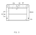
- FIG. 3 is a schematic diagram illustrating a cover opening structure being applied to an electronic device according to a first embodiment of the invention
- FIG. 4 is a partial cross-sectional diagram along a profile line A-A in FIG. 3
- a cover opening structure 400 may, for example, be applied to a Tablet PC, a Smart Phone or other portable electronic device.
- the cover opening structure 400 includes a case 410, a cover 420, a pushing button 430, a pushing unit 440 and an axle 450.
- the case 410 is a case of an electronic device 300.
- the cover 420 is disposed on the case 410, wherein the cover 420 has a first portion 422, a second portion 424 and a connecting portion 426 connected between the first portion 422 and the second portion 424.
- the connecting portion 426 is softer than the first portion 422 and the second portion 424, and thus when the cover 420 is opened, the connecting portion 426 may cause an angle variation between the first portion 422 and the second portion 424, so that a user may fold the cover 420 into a supporting mode and use the folded cover 420 to support the electronic device 300.
- the first portion 422 of the cover 420 has a first side 422a and the second portion 424 has a second side 424a, wherein the second side 424a is connected to the case 410.
- the connection mentioned herein may be referred to as: the cover 420 may be completely detached from the case 410 with convenience by using magnetic attraction, or the cover 420 is normally fixed on the case 410 by using mechanical means such as physical pivoting; and is designed according to actual requirements.
- the pushing button 430 is disposed on the case 410 and suitable for moving horizontally in relative to the case 410, wherein the pushing button 430 has a body 432 and an inserting portion 434 extended from the body 432.
- the pushing unit 440 has a first end 442, a second end 444 and a leaning portion 446 connected therebetween, and the inserting portion 434 is located between the body 432 and the first end 442.
- the axle 450 is disposed at the case 410.
- the leaning portion 446 of the present embodiment leans against the axle 450; however, in the other embodiments, the leaning portion 446 may also be ring-shaped, and the axle 450 passes through the ring-shaped leaning portion 446.
- a material of the pushing unit 440 may be metal, and a material of the pushing button 430 may be plastic, which are selected based on the actual requirements.
- the cover 420 further includes a pulling rod portion 428, and the pulling rod portion 428 is disposed at a first side 422a of the first portion 422. Hardness of the pulling rod portion 428 is greater than a hardness of the connecting portion 426, and the pushing button 430 is suitable for pushing the pulling rod portion 428.
- FIG. 5 is a schematic diagram illustrating a first portion of a cover being pushed up by a second end of a pushing unit when a pushing button is moved.
- the user may push the pushing button 430, so that the insertion portion 434 of the pushing button 430 further presses against the first end 442 of the pushing unit 440, and the pushing unit 440 rotates about the axle 450 while the first end 442 moves downward and the second end 444 moves upwards, so that the first portion 422 of the cover 420 is being pushed up as the second end 444 moves upward.
- the user may pull the first portion 422 of the cover 420 with less effort, so that the cover 420 is folded into a shape capable of supporting the electronic device 300, as shown in FIG. 6 .
- FIG. 7 is a schematic diagram illustrating a cover opening structure according to a second embodiment of the invention.
- the present embodiment is substantially similar to the first embodiment, and thus identical or similar elements are indicated with the same or similar reference number, whereas differences lie in that: a cover opening structure 500 of the present embodiment, other than including the case 410, the cover 420 and the axle 450, the pushing button 430 described in the previous embodiment is replaced with a Z-shaped pressing button 510; and as compared to the first embodiment, which the first portion 422 of the cover 420 is being pushed up by moving the pushing button 430, the actuation means of the present embodiment is to press the pressing button 510 to push up the first portion 422 of the cover 420.
- the pushing unit 440 of the first embodiment is inserted into the pressing button 510 and integrated with the pressing button 510, wherein a material of the pressing button 510 is plastic, and the pushing unit 440 may be a metal plate; however, in the other embodiments, the pushing unit 440 may also be integrally formed with the pressing button 510 by using same material.
- the axle 450 is disposed at the case 410, and the pressing button 510 is pivoted on the axle 450, exposed outside of the case 410 and suitable for rotating about the axle 450 in relative to the case 410, wherein the first end 442 of the pressing button 510 is exposed outside of the case 410 and the second end 444 leans against the first portion 422 of the cover 420.
- rotation gaps G1 and G2 are configured between the pressing button 510 and the case 410 to provide a rotation space for the pressing button 510.
- the user may enable the first portion of the cover to detach from the case in advance by means of the press button or the pushing button, and then the user may lift up the cover in relative to the case of the electronic device with less strength. Therefore, in terms of the user, the greatest strength lies in detaching the first portion of the cover from the case; however, it takes less strength by adopting the cover opening structure, thereby having an ease of use.
Landscapes
- Engineering & Computer Science (AREA)
- Theoretical Computer Science (AREA)
- Computer Hardware Design (AREA)
- Human Computer Interaction (AREA)
- Physics & Mathematics (AREA)
- General Engineering & Computer Science (AREA)
- General Physics & Mathematics (AREA)
- Microelectronics & Electronic Packaging (AREA)
- Telephone Set Structure (AREA)
- Casings For Electric Apparatus (AREA)
Abstract
Description
- The invention relates to a cover opening structure, and more particularly, to a cover opening structure enabling a user to open a cover with convenience.
- With diversification in the development of mobile application (mobile App), current flat panel products gradually derive with other new usages from the original hand-held use features. As the time being spent by user on a Tablet PC increases, it requires a supporting structure to support the Tablet PC so as to provide the user with long-term use.
FIG. 1 is a schematic diagram illustrating use states of a Tablet PC and an accessory cover thereof, andFIG. 2 is a schematic diagram illustrating a supporting structure being disposed at the back side of the Tablet PC. As shown inFIG. 1 , it can be seen that a foldable cover 200a may support a Tablet PC 100a with different means. As shown inFIG. 2 , asupport piece 200b is used to support a Tablet PC 100b. Either use the supporting means illustrated inFIG. 1 or inFIG. 2 , both supporting means are all provided for bringing the user with an ease of use. - The invention provides a cover opening structure enabling a cover to open up from an electronic device with convenience.
- The cover opening structure of the invention includes a case, a cover, a pushing button, a pushing unit and an axle. The cover has at least a first portion, a second portion and a connecting portion connected to the first portion and the second portion, wherein the connecting portion is softer than the first portion and the second portion. The first portion has a first side and the second portion has a second side, wherein the second side is connected to the case. The pushing button is disposed on the case and suitable for moving horizontally in relative to the case, wherein the pushing button has a body and an inserting portion extended from the body. The pushing unit has a first end, a second end and a leaning portion connected between the first end and the second end. The inserting portion is located between the body and the first end. The axle is disposed at the case, and the leaning portion leans against the axle. The inserting portion enables the pushing unit to rotate about the axle while the first end moves downward and the second end moves upward when the pushing button is moved, so as to push up the first portion of the cover.
- The cover opening structure includes a case, a cover, an axle and a pressing button. The cover has at least one first portion, a second portion and a connecting portion connected to the first portion and the second portion, wherein the connecting portion is softer than the first portion and the second portion. The first portion has a first side and the second portion has a second side, wherein the second side is connected to the case. The axle is disposed at the case, the pressing button is pivoted on the axle and exposed outside of the case, and suitable for rotating about the axle in relative to the case, wherein the pressing button has a first end and a second end that are connected together perpendicularly, and the second end leans against the first portion. When the pressing button is subjected by pressure to rotate about the axle in relative to the case, the second end pushes up the first portion of the cover.
- In view of above, the cover opening structure of the invention allows the user to open up the cover in relative to the case of the electronic device with less effort by means of pushing or pressing.
- In order to make the aforementioned and other features and advantages of the present application more comprehensible, several embodiments accompanied with figures are described in detail below.
- The accompanying drawings are included to provide a further understanding of the application, and are incorporated in and constitute a part of this specification. The drawings illustrate embodiments of the application and, together with the description, serve to explain the principles of the application.
-
FIG. 1 is a schematic diagram illustrating use states of a Tablet PC and an accessory cover thereof. -
FIG. 2 is a schematic diagram illustrating a supporting structure being disposed at the back side of the Tablet PC. -
FIG. 3 is a schematic diagram illustrating a cover opening structure being applied to an electronic device according to a first embodiment of the invention. -
FIG. 4 is a partial cross-sectional diagram along a profile line A-A inFIG. 3 . -
FIG. 5 is a schematic diagram illustrating a first portion of a cover being pushed up by a second end of a pushing unit when a pushing button is moved. -
FIG. 6 is a schematic diagram illustrating the electronic device being supported by the cover. -
FIG. 7 is a schematic diagram illustrating a cover opening structure according to a second embodiment of the invention. -
FIG. 3 is a schematic diagram illustrating a cover opening structure being applied to an electronic device according to a first embodiment of the invention, andFIG. 4 is a partial cross-sectional diagram along a profile line A-A inFIG. 3 . Referring toFIG. 3 andFIG. 4 at the same time, acover opening structure 400 may, for example, be applied to a Tablet PC, a Smart Phone or other portable electronic device. Thecover opening structure 400 includes acase 410, acover 420, a pushingbutton 430, a pushingunit 440 and anaxle 450. Thecase 410 is a case of anelectronic device 300. Thecover 420 is disposed on thecase 410, wherein thecover 420 has afirst portion 422, asecond portion 424 and a connectingportion 426 connected between thefirst portion 422 and thesecond portion 424. The connectingportion 426 is softer than thefirst portion 422 and thesecond portion 424, and thus when thecover 420 is opened, the connectingportion 426 may cause an angle variation between thefirst portion 422 and thesecond portion 424, so that a user may fold thecover 420 into a supporting mode and use the foldedcover 420 to support theelectronic device 300. - Based on the above, the
first portion 422 of thecover 420 has afirst side 422a and thesecond portion 424 has asecond side 424a, wherein thesecond side 424a is connected to thecase 410. The connection mentioned herein may be referred to as: thecover 420 may be completely detached from thecase 410 with convenience by using magnetic attraction, or thecover 420 is normally fixed on thecase 410 by using mechanical means such as physical pivoting; and is designed according to actual requirements. The pushingbutton 430 is disposed on thecase 410 and suitable for moving horizontally in relative to thecase 410, wherein the pushingbutton 430 has abody 432 and aninserting portion 434 extended from thebody 432. The pushingunit 440 has afirst end 442, asecond end 444 and aleaning portion 446 connected therebetween, and theinserting portion 434 is located between thebody 432 and thefirst end 442. Theaxle 450 is disposed at thecase 410. Theleaning portion 446 of the present embodiment leans against theaxle 450; however, in the other embodiments, theleaning portion 446 may also be ring-shaped, and theaxle 450 passes through the ring-shaped leaning portion 446. - Based from the above, a material of the pushing
unit 440 may be metal, and a material of the pushingbutton 430 may be plastic, which are selected based on the actual requirements. In addition, thecover 420 further includes apulling rod portion 428, and thepulling rod portion 428 is disposed at afirst side 422a of thefirst portion 422. Hardness of thepulling rod portion 428 is greater than a hardness of the connectingportion 426, and the pushingbutton 430 is suitable for pushing thepulling rod portion 428. -
FIG. 5 is a schematic diagram illustrating a first portion of a cover being pushed up by a second end of a pushing unit when a pushing button is moved. Referring toFIG. 3 ,FIG. 4 andFIG. 5 at the same time, when the user is to open up thecover 420 in relative to thecase 410 of theelectronic device 300, the user may push thepushing button 430, so that theinsertion portion 434 of the pushingbutton 430 further presses against thefirst end 442 of the pushingunit 440, and the pushingunit 440 rotates about theaxle 450 while thefirst end 442 moves downward and thesecond end 444 moves upwards, so that thefirst portion 422 of thecover 420 is being pushed up as thesecond end 444 moves upward. After thefirst portion 422 of thecover 420 is being pushed up, the user may pull thefirst portion 422 of thecover 420 with less effort, so that thecover 420 is folded into a shape capable of supporting theelectronic device 300, as shown inFIG. 6 . -
FIG. 7 is a schematic diagram illustrating a cover opening structure according to a second embodiment of the invention. Referring toFIG. 7 , the present embodiment is substantially similar to the first embodiment, and thus identical or similar elements are indicated with the same or similar reference number, whereas differences lie in that: a coveropening structure 500 of the present embodiment, other than including thecase 410, thecover 420 and theaxle 450, the pushingbutton 430 described in the previous embodiment is replaced with a Z-shapedpressing button 510; and as compared to the first embodiment, which thefirst portion 422 of thecover 420 is being pushed up by moving the pushingbutton 430, the actuation means of the present embodiment is to press thepressing button 510 to push up thefirst portion 422 of thecover 420. - In detail, in the present embodiment, the pushing
unit 440 of the first embodiment is inserted into thepressing button 510 and integrated with thepressing button 510, wherein a material of thepressing button 510 is plastic, and the pushingunit 440 may be a metal plate; however, in the other embodiments, the pushingunit 440 may also be integrally formed with thepressing button 510 by using same material. In addition, theaxle 450 is disposed at thecase 410, and thepressing button 510 is pivoted on theaxle 450, exposed outside of thecase 410 and suitable for rotating about theaxle 450 in relative to thecase 410, wherein thefirst end 442 of thepressing button 510 is exposed outside of thecase 410 and thesecond end 444 leans against thefirst portion 422 of thecover 420. - Moreover, in response to the rotation of the
pressing button 510, rotation gaps G1 and G2 are configured between thepressing button 510 and thecase 410 to provide a rotation space for thepressing button 510. - Continuously referring to
FIG. 7 , when the user is to open up thecover 420 in relative to thecase 410 of theelectronic device 300, the user applies force to thefirst end 442 of thepressing button 510, and when thefirst end 442 is subjected by pressure while thepressing button 510 rotates about theaxle 450 in relative to thecase 410, thesecond end 444 rotates upward to push up thefirst portion 422 of thecover 420. - In summary, as the cover opening structure of the invention is applied to the electronic device, the user may enable the first portion of the cover to detach from the case in advance by means of the press button or the pushing button, and then the user may lift up the cover in relative to the case of the electronic device with less strength. Therefore, in terms of the user, the greatest strength lies in detaching the first portion of the cover from the case; however, it takes less strength by adopting the cover opening structure, thereby having an ease of use.
Claims (10)
- A cover opening structure (400) comprising:a case (410);a cover (420) having at least one first portion (422), a second portion (424) and a connecting portion (426) connected to the first portion (422) and the second portion (424), wherein the connecting portion (426) is softer than the first portion (422) and the second portion (424), the first portion (422) has a first side (422a) and the second portion (424) has a second side (424a), wherein the second side (424a) is connected to the case (410);a pushing button (430) disposed on the case (410) and suitable for moving horizontally in relative to the case (410), wherein the pushing button (430) has a body (432) and an inserting portion (434) extended from the body (432);a pushing unit (440) having a first end (442), a second end (444) and a leaning portion (446) connected between the first end (442) and the second end (444), and the inserting portion (434) located between the body (432) and the first end (442); andan axle (450) disposed at the case (410), the leaning portion (446) leaning against the axle (450), and the inserting portion (434) enabling the pushing unit (440) to rotate about the axle (450) while the first end (442) moves downward and the second end (444) moves upward when the pushing button (430) is moved, so as to push up the first portion (422) of the cover (420).
- The cover opening structure (400) as recited in claim 1, wherein a material of the pushing unit (440) is metal.
- The cover opening structure (400) as recited in claim 1, wherein the cover (420) further comprises a pulling rod portion (428) disposed at the first side (422a) of the first portion (422).
- The cover opening structure (400) as recited in claim 3, wherein hardness of the pulling rod portion (428) is greater than hardness of the connecting portion (426).
- The cover opening structure (400) as recited in claim 1, wherein a material of the pushing button (430) is plastic.
- The cover opening structure (400) as recited in claim 1, wherein the case (410) is a case of an electronic device.
- A cover opening structure (500) comprising:a case (410);a cover (420) having at least a first portion (422), a second portion (424) and a connecting portion (426) connected to the first portion (422) and the second portion (424), wherein the connecting portion (426) is softer than the first portion (422) and the second portion (424), the first portion (422) has a first side (422a) and the second portion (424) has a second side (424a), wherein the second side (424a) is connected to the case (410);an axle (450) disposed at the case (410);a pressing button (510) pivoted on the axle (450) and exposed outside of the case (410), suitable for rotating about the axle (450) in relative to the case (410), wherein the pressing button (510) has a first end (442) and a second end (444), the second end (444) leans against the first portion (422), and when the pressing button (510) is subjected by pressure to rotate about the axle (450) in relative to the case (410), the second end (444) pushes up the first portion (422) of the cover (420).
- The cover opening structure (500) as recited in claim 7, wherein the pressing button (510) and the case (410) have a rotation gap (G1, G2) therebetween to provide a rotation space for the pressing button (510).
- The cover opening structure (500) as recited in claim 7, wherein a material of the pressing button (510) is plastic.
- The cover opening structure (500) as recited in claim 7, wherein the case (410) is a case of an electronic device.
Applications Claiming Priority (1)
| Application Number | Priority Date | Filing Date | Title |
|---|---|---|---|
| TW102224520U TWM477604U (en) | 2013-12-26 | 2013-12-26 | Cover opening structure |
Publications (2)
| Publication Number | Publication Date |
|---|---|
| EP2891939A1 true EP2891939A1 (en) | 2015-07-08 |
| EP2891939B1 EP2891939B1 (en) | 2016-09-21 |
Family
ID=51295014
Family Applications (1)
| Application Number | Title | Priority Date | Filing Date |
|---|---|---|---|
| EP14161668.0A Not-in-force EP2891939B1 (en) | 2013-12-26 | 2014-03-26 | Cover opening structure |
Country Status (3)
| Country | Link |
|---|---|
| US (1) | US9591777B2 (en) |
| EP (1) | EP2891939B1 (en) |
| TW (1) | TWM477604U (en) |
Citations (2)
| Publication number | Priority date | Publication date | Assignee | Title |
|---|---|---|---|---|
| US6129237A (en) * | 1997-12-08 | 2000-10-10 | Casio Computer Co., Ltd. | Structure for opening/closing a case cover |
| US20130301204A1 (en) * | 2012-05-11 | 2013-11-14 | Samsung Electronics Co. Ltd. | Portable terminal with detachable protection cover |
Family Cites Families (2)
| Publication number | Priority date | Publication date | Assignee | Title |
|---|---|---|---|---|
| US4259568A (en) * | 1979-10-12 | 1981-03-31 | Henning Dynesen A/S | Combined casing and operational support for a pocket calculator |
| WO1999001050A1 (en) * | 1997-07-03 | 1999-01-14 | Yoshida Industry Co., Ltd. | Gastight makeup material container |
-
2013
- 2013-12-26 TW TW102224520U patent/TWM477604U/en not_active IP Right Cessation
-
2014
- 2014-03-14 US US14/210,471 patent/US9591777B2/en not_active Expired - Fee Related
- 2014-03-26 EP EP14161668.0A patent/EP2891939B1/en not_active Not-in-force
Patent Citations (2)
| Publication number | Priority date | Publication date | Assignee | Title |
|---|---|---|---|---|
| US6129237A (en) * | 1997-12-08 | 2000-10-10 | Casio Computer Co., Ltd. | Structure for opening/closing a case cover |
| US20130301204A1 (en) * | 2012-05-11 | 2013-11-14 | Samsung Electronics Co. Ltd. | Portable terminal with detachable protection cover |
Also Published As
| Publication number | Publication date |
|---|---|
| TWM477604U (en) | 2014-05-01 |
| EP2891939B1 (en) | 2016-09-21 |
| US9591777B2 (en) | 2017-03-07 |
| US20150189773A1 (en) | 2015-07-02 |
Similar Documents
| Publication | Publication Date | Title |
|---|---|---|
| CN204127585U (en) | Positionable lifting bracket structure | |
| CN204793416U (en) | Card holds in palm remove device and electronic equipment | |
| WO2018053480A1 (en) | Keyboard with tablet stand | |
| CN105556413A (en) | Mobile computing device dock | |
| CN106681433B (en) | A kind of tablet computer and pedestal with pedestal | |
| CN203032965U (en) | Screen film pasting device with changeable mobile phone holder | |
| EP2891939B1 (en) | Cover opening structure | |
| CN204257939U (en) | For deck and the mobile terminal of mobile terminal | |
| CN108571640A (en) | Mobile terminal holder | |
| CN204257940U (en) | For deck and the mobile terminal of mobile terminal | |
| CN204257937U (en) | For deck and the mobile terminal of mobile terminal | |
| CN211344498U (en) | Electronic device | |
| KR101793374B1 (en) | Cradle and case for smartphones with window | |
| CN104409261B (en) | Keyboard and portable electronic devices | |
| KR200464019Y1 (en) | The pouch for a portable terminal having standing function | |
| CN203761720U (en) | Lid opening structure | |
| CN105788930A (en) | Rotating key remote controller | |
| CN102118935A (en) | Sliding type electronic device | |
| CN209887494U (en) | Cell-phone shell processingequipment | |
| TW201428451A (en) | Portable electronic apparatus | |
| KR20150129978A (en) | Supporting means for smartphone and tablet pc and case for smartphone and tablet pc having the same | |
| CN203761440U (en) | Sim card fixing device | |
| CN104065778A (en) | Telephone supporting arm tray | |
| CN102118936B (en) | Sliding type electronic device | |
| CN108683774A (en) | A kind of mobile phone support device |
Legal Events
| Date | Code | Title | Description |
|---|---|---|---|
| PUAI | Public reference made under article 153(3) epc to a published international application that has entered the european phase |
Free format text: ORIGINAL CODE: 0009012 |
|
| 17P | Request for examination filed |
Effective date: 20140326 |
|
| AK | Designated contracting states |
Kind code of ref document: A1 Designated state(s): AL AT BE BG CH CY CZ DE DK EE ES FI FR GB GR HR HU IE IS IT LI LT LU LV MC MK MT NL NO PL PT RO RS SE SI SK SM TR |
|
| AX | Request for extension of the european patent |
Extension state: BA ME |
|
| R17P | Request for examination filed (corrected) |
Effective date: 20150925 |
|
| RBV | Designated contracting states (corrected) |
Designated state(s): AL AT BE BG CH CY CZ DE DK EE ES FI FR GB GR HR HU IE IS IT LI LT LU LV MC MK MT NL NO PL PT RO RS SE SI SK SM TR |
|
| GRAP | Despatch of communication of intention to grant a patent |
Free format text: ORIGINAL CODE: EPIDOSNIGR1 |
|
| GRAJ | Information related to disapproval of communication of intention to grant by the applicant or resumption of examination proceedings by the epo deleted |
Free format text: ORIGINAL CODE: EPIDOSDIGR1 |
|
| GRAJ | Information related to disapproval of communication of intention to grant by the applicant or resumption of examination proceedings by the epo deleted |
Free format text: ORIGINAL CODE: EPIDOSDIGR1 |
|
| GRAP | Despatch of communication of intention to grant a patent |
Free format text: ORIGINAL CODE: EPIDOSNIGR1 |
|
| GRAP | Despatch of communication of intention to grant a patent |
Free format text: ORIGINAL CODE: EPIDOSNIGR1 |
|
| INTG | Intention to grant announced |
Effective date: 20160329 |
|
| INTG | Intention to grant announced |
Effective date: 20160412 |
|
| INTG | Intention to grant announced |
Effective date: 20160420 |
|
| GRAS | Grant fee paid |
Free format text: ORIGINAL CODE: EPIDOSNIGR3 |
|
| GRAA | (expected) grant |
Free format text: ORIGINAL CODE: 0009210 |
|
| AK | Designated contracting states |
Kind code of ref document: B1 Designated state(s): AL AT BE BG CH CY CZ DE DK EE ES FI FR GB GR HR HU IE IS IT LI LT LU LV MC MK MT NL NO PL PT RO RS SE SI SK SM TR |
|
| REG | Reference to a national code |
Ref country code: GB Ref legal event code: FG4D |
|
| REG | Reference to a national code |
Ref country code: CH Ref legal event code: EP |
|
| REG | Reference to a national code |
Ref country code: AT Ref legal event code: REF Ref document number: 831542 Country of ref document: AT Kind code of ref document: T Effective date: 20161015 |
|
| REG | Reference to a national code |
Ref country code: IE Ref legal event code: FG4D |
|
| REG | Reference to a national code |
Ref country code: DE Ref legal event code: R096 Ref document number: 602014003731 Country of ref document: DE |
|
| REG | Reference to a national code |
Ref country code: LT Ref legal event code: MG4D Ref country code: NL Ref legal event code: MP Effective date: 20160921 |
|
| PG25 | Lapsed in a contracting state [announced via postgrant information from national office to epo] |
Ref country code: RS Free format text: LAPSE BECAUSE OF FAILURE TO SUBMIT A TRANSLATION OF THE DESCRIPTION OR TO PAY THE FEE WITHIN THE PRESCRIBED TIME-LIMIT Effective date: 20160921 Ref country code: NO Free format text: LAPSE BECAUSE OF FAILURE TO SUBMIT A TRANSLATION OF THE DESCRIPTION OR TO PAY THE FEE WITHIN THE PRESCRIBED TIME-LIMIT Effective date: 20161221 Ref country code: LT Free format text: LAPSE BECAUSE OF FAILURE TO SUBMIT A TRANSLATION OF THE DESCRIPTION OR TO PAY THE FEE WITHIN THE PRESCRIBED TIME-LIMIT Effective date: 20160921 Ref country code: FI Free format text: LAPSE BECAUSE OF FAILURE TO SUBMIT A TRANSLATION OF THE DESCRIPTION OR TO PAY THE FEE WITHIN THE PRESCRIBED TIME-LIMIT Effective date: 20160921 |
|
| REG | Reference to a national code |
Ref country code: AT Ref legal event code: MK05 Ref document number: 831542 Country of ref document: AT Kind code of ref document: T Effective date: 20160921 |
|
| PG25 | Lapsed in a contracting state [announced via postgrant information from national office to epo] |
Ref country code: GR Free format text: LAPSE BECAUSE OF FAILURE TO SUBMIT A TRANSLATION OF THE DESCRIPTION OR TO PAY THE FEE WITHIN THE PRESCRIBED TIME-LIMIT Effective date: 20161222 Ref country code: SE Free format text: LAPSE BECAUSE OF FAILURE TO SUBMIT A TRANSLATION OF THE DESCRIPTION OR TO PAY THE FEE WITHIN THE PRESCRIBED TIME-LIMIT Effective date: 20160921 Ref country code: NL Free format text: LAPSE BECAUSE OF FAILURE TO SUBMIT A TRANSLATION OF THE DESCRIPTION OR TO PAY THE FEE WITHIN THE PRESCRIBED TIME-LIMIT Effective date: 20160921 Ref country code: LV Free format text: LAPSE BECAUSE OF FAILURE TO SUBMIT A TRANSLATION OF THE DESCRIPTION OR TO PAY THE FEE WITHIN THE PRESCRIBED TIME-LIMIT Effective date: 20160921 |
|
| PG25 | Lapsed in a contracting state [announced via postgrant information from national office to epo] |
Ref country code: EE Free format text: LAPSE BECAUSE OF FAILURE TO SUBMIT A TRANSLATION OF THE DESCRIPTION OR TO PAY THE FEE WITHIN THE PRESCRIBED TIME-LIMIT Effective date: 20160921 Ref country code: RO Free format text: LAPSE BECAUSE OF FAILURE TO SUBMIT A TRANSLATION OF THE DESCRIPTION OR TO PAY THE FEE WITHIN THE PRESCRIBED TIME-LIMIT Effective date: 20160921 |
|
| PG25 | Lapsed in a contracting state [announced via postgrant information from national office to epo] |
Ref country code: BG Free format text: LAPSE BECAUSE OF FAILURE TO SUBMIT A TRANSLATION OF THE DESCRIPTION OR TO PAY THE FEE WITHIN THE PRESCRIBED TIME-LIMIT Effective date: 20161221 Ref country code: IS Free format text: LAPSE BECAUSE OF FAILURE TO SUBMIT A TRANSLATION OF THE DESCRIPTION OR TO PAY THE FEE WITHIN THE PRESCRIBED TIME-LIMIT Effective date: 20170121 Ref country code: PL Free format text: LAPSE BECAUSE OF FAILURE TO SUBMIT A TRANSLATION OF THE DESCRIPTION OR TO PAY THE FEE WITHIN THE PRESCRIBED TIME-LIMIT Effective date: 20160921 Ref country code: PT Free format text: LAPSE BECAUSE OF FAILURE TO SUBMIT A TRANSLATION OF THE DESCRIPTION OR TO PAY THE FEE WITHIN THE PRESCRIBED TIME-LIMIT Effective date: 20170123 Ref country code: SK Free format text: LAPSE BECAUSE OF FAILURE TO SUBMIT A TRANSLATION OF THE DESCRIPTION OR TO PAY THE FEE WITHIN THE PRESCRIBED TIME-LIMIT Effective date: 20160921 Ref country code: BE Free format text: LAPSE BECAUSE OF FAILURE TO SUBMIT A TRANSLATION OF THE DESCRIPTION OR TO PAY THE FEE WITHIN THE PRESCRIBED TIME-LIMIT Effective date: 20160921 Ref country code: ES Free format text: LAPSE BECAUSE OF FAILURE TO SUBMIT A TRANSLATION OF THE DESCRIPTION OR TO PAY THE FEE WITHIN THE PRESCRIBED TIME-LIMIT Effective date: 20160921 Ref country code: CZ Free format text: LAPSE BECAUSE OF FAILURE TO SUBMIT A TRANSLATION OF THE DESCRIPTION OR TO PAY THE FEE WITHIN THE PRESCRIBED TIME-LIMIT Effective date: 20160921 Ref country code: AT Free format text: LAPSE BECAUSE OF FAILURE TO SUBMIT A TRANSLATION OF THE DESCRIPTION OR TO PAY THE FEE WITHIN THE PRESCRIBED TIME-LIMIT Effective date: 20160921 Ref country code: SM Free format text: LAPSE BECAUSE OF FAILURE TO SUBMIT A TRANSLATION OF THE DESCRIPTION OR TO PAY THE FEE WITHIN THE PRESCRIBED TIME-LIMIT Effective date: 20160921 |
|
| REG | Reference to a national code |
Ref country code: DE Ref legal event code: R097 Ref document number: 602014003731 Country of ref document: DE |
|
| PG25 | Lapsed in a contracting state [announced via postgrant information from national office to epo] |
Ref country code: IT Free format text: LAPSE BECAUSE OF FAILURE TO SUBMIT A TRANSLATION OF THE DESCRIPTION OR TO PAY THE FEE WITHIN THE PRESCRIBED TIME-LIMIT Effective date: 20160921 |
|
| PLBE | No opposition filed within time limit |
Free format text: ORIGINAL CODE: 0009261 |
|
| STAA | Information on the status of an ep patent application or granted ep patent |
Free format text: STATUS: NO OPPOSITION FILED WITHIN TIME LIMIT |
|
| PG25 | Lapsed in a contracting state [announced via postgrant information from national office to epo] |
Ref country code: DK Free format text: LAPSE BECAUSE OF FAILURE TO SUBMIT A TRANSLATION OF THE DESCRIPTION OR TO PAY THE FEE WITHIN THE PRESCRIBED TIME-LIMIT Effective date: 20160921 |
|
| 26N | No opposition filed |
Effective date: 20170622 |
|
| REG | Reference to a national code |
Ref country code: CH Ref legal event code: PL |
|
| PG25 | Lapsed in a contracting state [announced via postgrant information from national office to epo] |
Ref country code: MC Free format text: LAPSE BECAUSE OF FAILURE TO SUBMIT A TRANSLATION OF THE DESCRIPTION OR TO PAY THE FEE WITHIN THE PRESCRIBED TIME-LIMIT Effective date: 20160921 Ref country code: SI Free format text: LAPSE BECAUSE OF FAILURE TO SUBMIT A TRANSLATION OF THE DESCRIPTION OR TO PAY THE FEE WITHIN THE PRESCRIBED TIME-LIMIT Effective date: 20160921 |
|
| REG | Reference to a national code |
Ref country code: IE Ref legal event code: MM4A |
|
| REG | Reference to a national code |
Ref country code: FR Ref legal event code: ST Effective date: 20171130 |
|
| PG25 | Lapsed in a contracting state [announced via postgrant information from national office to epo] |
Ref country code: FR Free format text: LAPSE BECAUSE OF NON-PAYMENT OF DUE FEES Effective date: 20170331 Ref country code: LU Free format text: LAPSE BECAUSE OF NON-PAYMENT OF DUE FEES Effective date: 20170326 |
|
| PG25 | Lapsed in a contracting state [announced via postgrant information from national office to epo] |
Ref country code: LI Free format text: LAPSE BECAUSE OF NON-PAYMENT OF DUE FEES Effective date: 20170331 Ref country code: IE Free format text: LAPSE BECAUSE OF NON-PAYMENT OF DUE FEES Effective date: 20170326 Ref country code: CH Free format text: LAPSE BECAUSE OF NON-PAYMENT OF DUE FEES Effective date: 20170331 |
|
| PG25 | Lapsed in a contracting state [announced via postgrant information from national office to epo] |
Ref country code: MT Free format text: LAPSE BECAUSE OF NON-PAYMENT OF DUE FEES Effective date: 20170326 |
|
| PG25 | Lapsed in a contracting state [announced via postgrant information from national office to epo] |
Ref country code: AL Free format text: LAPSE BECAUSE OF FAILURE TO SUBMIT A TRANSLATION OF THE DESCRIPTION OR TO PAY THE FEE WITHIN THE PRESCRIBED TIME-LIMIT Effective date: 20160921 |
|
| GBPC | Gb: european patent ceased through non-payment of renewal fee |
Effective date: 20180326 |
|
| PG25 | Lapsed in a contracting state [announced via postgrant information from national office to epo] |
Ref country code: GB Free format text: LAPSE BECAUSE OF NON-PAYMENT OF DUE FEES Effective date: 20180326 |
|
| PG25 | Lapsed in a contracting state [announced via postgrant information from national office to epo] |
Ref country code: HU Free format text: LAPSE BECAUSE OF FAILURE TO SUBMIT A TRANSLATION OF THE DESCRIPTION OR TO PAY THE FEE WITHIN THE PRESCRIBED TIME-LIMIT; INVALID AB INITIO Effective date: 20140326 |
|
| PG25 | Lapsed in a contracting state [announced via postgrant information from national office to epo] |
Ref country code: CY Free format text: LAPSE BECAUSE OF FAILURE TO SUBMIT A TRANSLATION OF THE DESCRIPTION OR TO PAY THE FEE WITHIN THE PRESCRIBED TIME-LIMIT Effective date: 20160921 |
|
| PG25 | Lapsed in a contracting state [announced via postgrant information from national office to epo] |
Ref country code: MK Free format text: LAPSE BECAUSE OF FAILURE TO SUBMIT A TRANSLATION OF THE DESCRIPTION OR TO PAY THE FEE WITHIN THE PRESCRIBED TIME-LIMIT Effective date: 20160921 |
|
| PG25 | Lapsed in a contracting state [announced via postgrant information from national office to epo] |
Ref country code: TR Free format text: LAPSE BECAUSE OF FAILURE TO SUBMIT A TRANSLATION OF THE DESCRIPTION OR TO PAY THE FEE WITHIN THE PRESCRIBED TIME-LIMIT Effective date: 20160921 |
|
| PG25 | Lapsed in a contracting state [announced via postgrant information from national office to epo] |
Ref country code: HR Free format text: LAPSE BECAUSE OF FAILURE TO SUBMIT A TRANSLATION OF THE DESCRIPTION OR TO PAY THE FEE WITHIN THE PRESCRIBED TIME-LIMIT Effective date: 20160921 |
|
| PGFP | Annual fee paid to national office [announced via postgrant information from national office to epo] |
Ref country code: DE Payment date: 20240206 Year of fee payment: 11 |
|
| REG | Reference to a national code |
Ref country code: DE Ref legal event code: R119 Ref document number: 602014003731 Country of ref document: DE |
|
| PG25 | Lapsed in a contracting state [announced via postgrant information from national office to epo] |
Ref country code: DE Free format text: LAPSE BECAUSE OF NON-PAYMENT OF DUE FEES Effective date: 20251001 |