EP2891905A1 - Method for manufacturing optical lens - Google Patents
Method for manufacturing optical lens Download PDFInfo
- Publication number
- EP2891905A1 EP2891905A1 EP13832606.1A EP13832606A EP2891905A1 EP 2891905 A1 EP2891905 A1 EP 2891905A1 EP 13832606 A EP13832606 A EP 13832606A EP 2891905 A1 EP2891905 A1 EP 2891905A1
- Authority
- EP
- European Patent Office
- Prior art keywords
- coating
- coating solution
- optical lens
- substrate
- lens
- Prior art date
- Legal status (The legal status is an assumption and is not a legal conclusion. Google has not performed a legal analysis and makes no representation as to the accuracy of the status listed.)
- Withdrawn
Links
- 238000000034 method Methods 0.000 title claims abstract description 54
- 230000003287 optical effect Effects 0.000 title claims abstract description 47
- 238000004519 manufacturing process Methods 0.000 title claims abstract description 26
- 238000000576 coating method Methods 0.000 claims abstract description 321
- 239000011248 coating agent Substances 0.000 claims abstract description 319
- 239000000758 substrate Substances 0.000 claims abstract description 101
- 230000002093 peripheral effect Effects 0.000 claims abstract description 33
- 238000005507 spraying Methods 0.000 claims description 2
- 238000002360 preparation method Methods 0.000 abstract description 7
- 239000007921 spray Substances 0.000 description 9
- 230000000052 comparative effect Effects 0.000 description 8
- OKKJLVBELUTLKV-UHFFFAOYSA-N Methanol Chemical compound OC OKKJLVBELUTLKV-UHFFFAOYSA-N 0.000 description 6
- 239000012530 fluid Substances 0.000 description 6
- 230000005484 gravity Effects 0.000 description 6
- 238000010438 heat treatment Methods 0.000 description 6
- 230000007423 decrease Effects 0.000 description 5
- 238000009826 distribution Methods 0.000 description 4
- KFZMGEQAYNKOFK-UHFFFAOYSA-N Isopropanol Chemical compound CC(C)O KFZMGEQAYNKOFK-UHFFFAOYSA-N 0.000 description 3
- 238000005096 rolling process Methods 0.000 description 3
- 239000002904 solvent Substances 0.000 description 3
- 229920001187 thermosetting polymer Polymers 0.000 description 3
- VEXZGXHMUGYJMC-UHFFFAOYSA-N Hydrochloric acid Chemical compound Cl VEXZGXHMUGYJMC-UHFFFAOYSA-N 0.000 description 2
- 230000015572 biosynthetic process Effects 0.000 description 2
- 239000003795 chemical substances by application Substances 0.000 description 2
- 238000007598 dipping method Methods 0.000 description 2
- 230000000694 effects Effects 0.000 description 2
- 238000005259 measurement Methods 0.000 description 2
- 239000000126 substance Substances 0.000 description 2
- BPSIOYPQMFLKFR-UHFFFAOYSA-N trimethoxy-[3-(oxiran-2-ylmethoxy)propyl]silane Chemical compound CO[Si](OC)(OC)CCCOCC1CO1 BPSIOYPQMFLKFR-UHFFFAOYSA-N 0.000 description 2
- XBIUWALDKXACEA-UHFFFAOYSA-N 3-[bis(2,4-dioxopentan-3-yl)alumanyl]pentane-2,4-dione Chemical compound CC(=O)C(C(C)=O)[Al](C(C(C)=O)C(C)=O)C(C(C)=O)C(C)=O XBIUWALDKXACEA-UHFFFAOYSA-N 0.000 description 1
- 241000511976 Hoya Species 0.000 description 1
- VYPSYNLAJGMNEJ-UHFFFAOYSA-N Silicium dioxide Chemical compound O=[Si]=O VYPSYNLAJGMNEJ-UHFFFAOYSA-N 0.000 description 1
- 239000003054 catalyst Substances 0.000 description 1
- 239000008119 colloidal silica Substances 0.000 description 1
- 230000003247 decreasing effect Effects 0.000 description 1
- 238000001035 drying Methods 0.000 description 1
- 230000007062 hydrolysis Effects 0.000 description 1
- 238000006460 hydrolysis reaction Methods 0.000 description 1
- 238000005286 illumination Methods 0.000 description 1
- 239000007788 liquid Substances 0.000 description 1
- 230000000116 mitigating effect Effects 0.000 description 1
- 150000003961 organosilicon compounds Chemical class 0.000 description 1
- 230000035939 shock Effects 0.000 description 1
- RMAQACBXLXPBSY-UHFFFAOYSA-N silicic acid Chemical compound O[Si](O)(O)O RMAQACBXLXPBSY-UHFFFAOYSA-N 0.000 description 1
- 238000003756 stirring Methods 0.000 description 1
- 230000000007 visual effect Effects 0.000 description 1
Images



Classifications
-
- G—PHYSICS
- G02—OPTICS
- G02B—OPTICAL ELEMENTS, SYSTEMS OR APPARATUS
- G02B1/00—Optical elements characterised by the material of which they are made; Optical coatings for optical elements
- G02B1/10—Optical coatings produced by application to, or surface treatment of, optical elements
- G02B1/14—Protective coatings, e.g. hard coatings
-
- B—PERFORMING OPERATIONS; TRANSPORTING
- B29—WORKING OF PLASTICS; WORKING OF SUBSTANCES IN A PLASTIC STATE IN GENERAL
- B29D—PRODUCING PARTICULAR ARTICLES FROM PLASTICS OR FROM SUBSTANCES IN A PLASTIC STATE
- B29D11/00—Producing optical elements, e.g. lenses or prisms
- B29D11/00009—Production of simple or compound lenses
-
- B—PERFORMING OPERATIONS; TRANSPORTING
- B29—WORKING OF PLASTICS; WORKING OF SUBSTANCES IN A PLASTIC STATE IN GENERAL
- B29D—PRODUCING PARTICULAR ARTICLES FROM PLASTICS OR FROM SUBSTANCES IN A PLASTIC STATE
- B29D11/00—Producing optical elements, e.g. lenses or prisms
- B29D11/00865—Applying coatings; tinting; colouring
-
- B—PERFORMING OPERATIONS; TRANSPORTING
- B29—WORKING OF PLASTICS; WORKING OF SUBSTANCES IN A PLASTIC STATE IN GENERAL
- B29D—PRODUCING PARTICULAR ARTICLES FROM PLASTICS OR FROM SUBSTANCES IN A PLASTIC STATE
- B29D11/00—Producing optical elements, e.g. lenses or prisms
- B29D11/00865—Applying coatings; tinting; colouring
- B29D11/00923—Applying coatings; tinting; colouring on lens surfaces for colouring or tinting
-
- G—PHYSICS
- G02—OPTICS
- G02B—OPTICAL ELEMENTS, SYSTEMS OR APPARATUS
- G02B1/00—Optical elements characterised by the material of which they are made; Optical coatings for optical elements
- G02B1/10—Optical coatings produced by application to, or surface treatment of, optical elements
-
- G—PHYSICS
- G02—OPTICS
- G02C—SPECTACLES; SUNGLASSES OR GOGGLES INSOFAR AS THEY HAVE THE SAME FEATURES AS SPECTACLES; CONTACT LENSES
- G02C7/00—Optical parts
- G02C7/02—Lenses; Lens systems ; Methods of designing lenses
-
- B—PERFORMING OPERATIONS; TRANSPORTING
- B05—SPRAYING OR ATOMISING IN GENERAL; APPLYING FLUENT MATERIALS TO SURFACES, IN GENERAL
- B05D—PROCESSES FOR APPLYING FLUENT MATERIALS TO SURFACES, IN GENERAL
- B05D1/00—Processes for applying liquids or other fluent materials
- B05D1/002—Processes for applying liquids or other fluent materials the substrate being rotated
-
- B—PERFORMING OPERATIONS; TRANSPORTING
- B05—SPRAYING OR ATOMISING IN GENERAL; APPLYING FLUENT MATERIALS TO SURFACES, IN GENERAL
- B05D—PROCESSES FOR APPLYING FLUENT MATERIALS TO SURFACES, IN GENERAL
- B05D1/00—Processes for applying liquids or other fluent materials
- B05D1/02—Processes for applying liquids or other fluent materials performed by spraying
-
- B—PERFORMING OPERATIONS; TRANSPORTING
- B05—SPRAYING OR ATOMISING IN GENERAL; APPLYING FLUENT MATERIALS TO SURFACES, IN GENERAL
- B05D—PROCESSES FOR APPLYING FLUENT MATERIALS TO SURFACES, IN GENERAL
- B05D2201/00—Polymeric substrate or laminate
-
- G—PHYSICS
- G02—OPTICS
- G02B—OPTICAL ELEMENTS, SYSTEMS OR APPARATUS
- G02B1/00—Optical elements characterised by the material of which they are made; Optical coatings for optical elements
- G02B1/04—Optical elements characterised by the material of which they are made; Optical coatings for optical elements made of organic materials, e.g. plastics
- G02B1/041—Lenses
-
- G—PHYSICS
- G02—OPTICS
- G02C—SPECTACLES; SUNGLASSES OR GOGGLES INSOFAR AS THEY HAVE THE SAME FEATURES AS SPECTACLES; CONTACT LENSES
- G02C2202/00—Generic optical aspects applicable to one or more of the subgroups of G02C7/00
- G02C2202/16—Laminated or compound lenses
Definitions
- the present invention relates to a method for manufacturing an optical lens, in which a coating solution is applied to an optical lens substrate while the optical lens substrate is rotated longitudinally.
- a plastic spectacle lens which is one of optical lenses, is provided with performance requested of the spectacle lens by performing various coating processes on its surface. These coating processes include a primer process, a process of forming a hard coat film, and a process of forming an antireflection film.
- a primer film formed by the primer process has a function of adding performance including shock resistance, adhesion, and crack mitigation using softness.
- a hard coat film needs to be very hard in order to improve scratch resistance.
- An outermost layer serving as the outer surface of the hard coat film is provided with an antireflection film. By arranging the antireflection film on the outermost layer, performance including the antireflection function, durability, and scratch resistance is further added.
- a primer layer at the time of the primer process and a hard coat layer serving as a hard coat film are formed by applying a coating solution to a lens surface.
- a method of applying a coating solution to a lens surface there are a dipping method, a spin coat method, a spray coat method, and an inkjet method as disclosed in patent literature 1.
- Application of a coating solution by the inkjet method disclosed in patent literature 1 is performed so that a spectacle lens substrate is rotated in a state in which the lens surface is directed vertically to uniform the film thickness on the entire lens surface.
- the film thickness is uniformed by dividing the lens surface into a plurality of concentric coating regions, and adjusting the amount of coating solution for the respective coating regions.
- interference fringes sometimes appear in a state in which various above-mentioned films are formed. It is known that the interference fringes are reduced by forming a thick hard coat film.
- Patent Literature 1 Japanese Patent Laid-Open No. 2004-122115
- the present inventor considers formation of a thicker hard coat film in order to improve the scratch resistance of a spectacle lens and reduce the generation of interference fringes mentioned above.
- the spray coat method and inkjet method can apply the coating solution to have a thickness of 10 ⁇ m or more.
- the coating solution was applied by the coating or the inkjet method to have a thickness of much more than 10 ⁇ m, a new problem in which the film thickness distribution became nonuniform arose.
- the cause of the nonuniform thickness distribution is considered to be so-called "dripping" because lens surfaces are formed from convex and concave curved surfaces.
- Dripping is a phenomenon in which a coating film gradually flows by its own weight and gathers on the lower side of a curvature surface (the peripheral portion of a convex curved surface or the central portion of a concave curved surface).
- the dripping can be suppressed to a certain degree by reducing the fluidity of the coating solution.
- the coating solution is less fluid, the film surface is formed not smoothly but into a so-called "orange peel surface".
- a method for manufacturing an optical lens comprising the steps of as a first coating condition, setting an angle of an axis of an optical lens substrate with respect to a horizontal direction within a predetermined angle range with reference to a convex surface side, as a second coating condition, rotating the optical lens substrate around the axis at a predetermined rotational speed at which a coating solution on a lens surface of the optical lens substrate is held in a coating position, and when the first coating condition and the second coating condition are satisfied, applying the coating solution to the lens surface of the optical lens substrate, the rotating step including a step of rotating the optical lens substrate within, as the predetermined angle range, a range between a maximum inclination angle of the axis at which a peripheral edge of the lens surface is positioned at the highest position of the lens surface of the optical lens substrate, and a maximum inclination angle of the axis at which the peripheral edge of the lens surface is positioned at the lowest position of the lens surface of the optical lens substrate.
- the direction of gravity acting on a coating solution adhered to an optical lens substrate alternately changes between the central direction and peripheral direction of a lens along with rotation of the optical lens substrate. For this reason, the coating solution adhered to the rotating optical lens substrate does not flow in one direction though it is fluid. Since the influence of gravity, which is a prime factor of "dripping", can be canceled by longitudinal rotation of the optical lens substrate, "dripping" of the coating solution flowing along the lens surface does not occur.
- the present invention can therefore provide a method for manufacturing an optical lens, in which a coating solution having normal fluidity can be applied thick to a lens surface without causing dripping.
- a method for manufacturing a spectacle lens according to this embodiment is a method for longitudinally rotating a spectacle lens substrate 1 shown in Fig. 1 , and applying a coating solution 3 to a lens surface 2 (a convex curved surface 2a and a concave curved surface 2b).
- a coating solution 3 for convenience, the coating solution 3 shown in Fig. 1 is illustrated to be thicker than it really is.
- the method for manufacturing a spectacle lens is executed by preparation step S1 and coating step S2, as shown in the flowchart of Fig. 2 .
- Preparation step S1 is a step for satisfying conditions (coating solution application conditions) for applying the coating solution 3.
- the coating solution application conditions are made up of first step S1A for satisfying the first condition to be described later, and second step S1B for satisfying the second condition to be described later.
- the first condition is satisfied when the angle of an axis C1 of the spectacle lens substrate 1 with respect to the horizontal direction falls within a predetermined angle range, as shown in Figs. 3 and 4 .
- the predetermined angle range is a range between an angle ⁇ 1 shown in Fig. 3 and an angle ⁇ 2 shown in Fig. 4 .
- the angle ⁇ 1 shown in Fig. 3 is the maximum inclination angle of the axis C1 when the spectacle lens substrate 1 is inclined clockwise in Fig.
- the angle ⁇ 2 shown in Fig. 4 is the maximum inclination angle of the axis C1 when the spectacle lens substrate 1 is inclined counterclockwise in Fig. 4 (direction in which the lens surface 2 formed from the convex curved surface 2a is directed downward) from a state in which the axis is horizontal, so as to keep a state in which the peripheral edge P of the lens surface 2 is positioned at the lowest position L of the lens surface 2.
- the second condition is satisfied by rotating the spectacle lens substrate 1 around the axis C1 at a predetermined rotational speed.
- the rotating apparatus 11 includes a support table 12, a rotation driving unit 14 that is supported by the support table 12 pivotally via a horizontal support shaft 13, and a holder 16 attached to a rotation shaft 15 of the rotation driving unit 14.
- the rotation driving unit 14 is inclined with respect to the support table 12 about the support shaft 13 so that the substrate 1 is inclined at a desired angle.
- the rotation driving unit 14 rotates the rotation shaft 15 at a predetermined constant rotational speed.
- the rotational speed can be, for example, about 15 to 50 RPM in correspondence with the fluidity of the coating solution 3.
- the rotational speed of the rotation shaft 15 is not limited to the above-mentioned range.
- the rotational speed is set to be relatively low.
- the rotational speed is set to be a speed at which the coating solution 3 does not flow toward the periphery of the lens surface 2 by the centrifugal force.
- the holder 16 holds the substrate 1.
- the holder 16 sandwiches the peripheral surface of the substrate 1 by a plurality of clamp members, and holds the substrate 1 on the same axis as the rotation shaft 15, details of which are not illustrated.
- Coating step S2 is a step of applying the coating solution 3 to the lens surface 2 of the substrate 1.
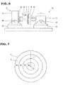
- the coating solution 3 is applied to the substrate 1 by a coating apparatus 21 shown in Fig. 6 .
- the coating apparatus 21 includes a support member 22, and a coating unit 24 that is supported by the support member 22 pivotally via a horizontal support shaft 23.
- the coating unit 24 supports a coating nozzle 26 via a translation mechanism 25.
- the coating nozzle 26 ejects the coating solution 3, and is driven to move in the radial direction of the substrate 1 by the translation mechanism 25.
- the ejection direction of the coating solution 3 can be changed appropriately by inclining the coating unit 24 with respect to the support member 22. More specifically, when the axis C1 of the substrate 1 is not horizontal and is inclined with respect to the horizontal direction, the coating unit 24 is inclined with respect to the support member 22 so as to eject the coating solution 3 with reference to the axis C1 of the substrate 1.
- the coating solution 3 is a general fluid coating solution such as a coating solution for forming a hard coat film or a coating solution for forming a photochronic film.
- the coating solution 3 is supplied from a supply device (not shown) to the coating nozzle 26.
- the coating nozzle 26 ejects small droplets of the coating solution 3 in a constant ejection amount by the spray coat method.
- the range where the coating nozzle 26 applies the coating solution 3 is narrower than the lens surface 2.
- the coating nozzle 26 is moved in the radial direction of the substrate 1 by the translation mechanism 25 in a state in which the coating solution 3 is sprayed to the lens surface 2.
- the coating solution 3 can be applied to the entire lens surface 2 by moving, in the radial direction of the substrate 1, the range where the coating nozzle 26 applies the coating solution 3 in a state in which the substrate 1 rotates.
- a coating nozzle that ejects a liquid coating solution 3 can be used as the coating nozzle 26.
- the translation mechanism 25 is configured to be able to change the moving speed in accordance with the position of the coating nozzle 26.
- the moving speed of the coating nozzle 26 becomes lower than that when the coating nozzle 26 faces the central portion of the substrate 1.
- preparation step S1 is executed.
- the substrate 1 is mounted on the rotating apparatus 11 and is stood to set the axis C1 at a predetermined inclination angle. Then, the substrate 1 is rotated at a predetermined rotational speed. The substrate 1 is stood so that the axis C1 becomes horizontal and the lens surface 2 extends vertically, as shown in, for example, Fig. 5 . The substrate 1 is driven to rotate at the predetermined rotational speed by the rotating apparatus 11.
- coating step S2 is executed.
- coating step S2 as shown in Fig. 6 , the coating nozzle 26 is caused to face the convex curved surface 2a or concave curved surface 2b of the lens surface 2 in a state in which the substrate 1 rotates longitudinally, as described above.
- the coating nozzle 26 ejects the coating solution 3.
- droplets of the coating solution 3 are ejected parallel to the axis C1 of the substrate 1 from the coating nozzle 26, and sprayed to the lens surface 2.
- the coating nozzle 26 according to this embodiment is driven to translate in the radial direction of the substrate 1 from the peripheral portion to central portion of the lens surface 2 by the translation mechanism 25.
- the coating solution 3 is sequentially applied to the substrate 1 during rotation from the peripheral portion toward the central portion.
- the applied coating solution 3 rotates together with the substrate 1.
- the direction of gravity acting on the coating solution 3 adhered to the substrate 1 alternately changes between the central direction and peripheral direction of the lens along with rotation of the substrate 1. Since the direction in which the gravity acts is not constant, the coating solution 3 does not flow in one direction and stays at the adhesion position though it is fluid. Since the influence of gravity, which is a prime factor of "dripping", can be canceled by longitudinal rotation of the spectacle lens substrate 1, "dripping" of the coating solution 3 flowing along the lens surface 2 does not occur.
- the coating solution 3 having normal fluidity can be applied thick to the lens surface 2 without causing dripping.
- a layer of the coating solution 3 with a thickness of at least 10 ⁇ m could be formed to have a uniform thickness on the entire lens surface 2.
- a coating solution for forming a hard coat film is used as the coating solution 3
- a hard coat film is formed on the substrate 1 at a film thickness of at least 10 ⁇ m.
- a spectacle lens having a hard coat film of such a thickness is much higher in scratch resistance than a conventional spectacle lens. In addition, interference fringes are reduced.
- the coating apparatus 21 shown in Fig. 6 is so illustrated that the coating nozzle 26 moves from top to bottom, but the present invention is not limited to this. That is, the same effects as those described above can be obtained even when the coating nozzle 26 moves from the lower end side to upper side (center side) of the lens surface 2 or the coating nozzle 26 moves horizontally.
- Coating step S2 ends after rotation of the substrate 1 continues by a predetermined time while maintaining a state in which the first and second conditions are satisfied even after the end of applying the coating solution 3.
- the time during which rotation of the substrate 1 continues is the time by which the fluidity of the coating solution 3 is lost to a degree at which the coating solution 3 applied to the substrate 1 does not move on the substrate 1.
- a coating solution 3 containing a volatile solvent increases in viscosity and decreases in fluidity when part of the solvent evaporates after application.
- An ultraviolet curing coating solution 3 increases in viscosity and decreases in fluidity upon irradiation with ultraviolet rays contained in the illumination in a coating environment.
- a curing step for curing the coating solution 3 can be executed in a state in which the coating solution 3 applied thick is held on the substrate 1 and so-called "dripping" does not occur.
- coating step S2 ends by stopping rotation of the substrate 1 after the fluidity of the coating solution 3 decreases.
- coating step S2 can be ended in a state in which the substrate 1 rotates.
- coating step S2 ends in a state in which the substrate 1 rotates, and the next step (for example, curing step) is executed in this state.
- This method can be implemented by, for example, moving the rotating apparatus 11 between the coating apparatus 21, and a curing apparatus (not shown) including a heater or ultraviolet lamp for curing the coating solution 3. More specifically, the substrate 1 is transferred from the coating apparatus 21 to the curing apparatus while it is driven to rotate by the rotating apparatus 11.
- FIG. 7 is a front view showing a lens surface for explaining another embodiment of coating step S2.
- Fig. 8 is a flowchart for explaining a method for manufacturing a spectacle lens according to this embodiment.
- the method for manufacturing a spectacle lens according to this embodiment is a method constituting an invention described in claim 2.
- the method for manufacturing a spectacle lens according to this embodiment is executed by, for example, preparation step S1, and coating step S2 including first to fourth divisional coating steps S2A to S2D to be described later, as shown in, for example, Fig. 8 .
- Coating step S2 is performed by changing a parameter regarding coating for respective coating regions #A to #D shown in Fig. 7 .
- the coating solution 3 is applied by the same method as that when the first embodiment is adopted. More specifically, a coating nozzle 26 sprays droplets of the coating solution 3 in a predetermined amount to a target coating position at part of a lens surface 2. In addition, the target coating position is moved in the radial direction of the lens surface 2.
- the coating nozzle 26 according to this embodiment translates from the periphery to center of the lens surface 2 (a convex curved surface 2a or a concave curved surface 2b).
- the parameter which is changed in regard to coating is the moving speed of the coating nozzle 26.
- This moving speed is set for the respective coating regions #A to #D shown in Fig. 7 .
- the plurality of coating regions #A to #D shown in Fig. 7 are formed by dividing a radius r from a center O to periphery of the lens surface 2 by every predetermined interval, and dividing the lens surface 2 by circles passing through the respective division points. The center of each circle passing through each division point coincides with the center of the lens surface 2. That is, the coating regions #A to #D are formed by dividing the lens surface 2 into a plurality of concentric circles.
- the moving speed of the coating nozzle 26 is set based on the areas of the coating regions #A to #D.
- the moving speed decreases as the area increases. That is, the moving speed becomes lowest when the coating solution 3 is applied to the first coating region #A including the peripheral edge of the lens surface 2, and increases when the coating solution 3 is applied to the second coating region #B positioned inside the first coating region #A in the radial direction. For this reason, the moving speed becomes higher when coating the third coating region #C than when coating the second coating region #B, and higher when coating the fourth coating region #D than when coating the third coating region #C.
- coating step S2 is executed by first to fourth divisional coating steps S2A to S2D.
- First divisional coating step S2A is a step of applying the coating solution 3 to the first coating region #A positioned on the outermost peripheral side out of the first to fourth coating regions #A to #D.
- the moving speed of the coating nozzle 26 at this time is set to be a speed (lowest speed) corresponding to the area of the first coating region #A.
- the coating solution 3 is applied to the second coating region #B in second divisional coating step S2B.
- the process advances from third divisional coating step S2C to fourth divisional coating step S2D.
- the coating nozzle 26 moves at moving speeds corresponding to areas to apply the coating solution 3 to even the third and fourth coating regions #C and #D.
- the coating solution 3 is applied in coating step S2 so that the adhesion amount of the coating solution 3 per unit area becomes a predetermined amount on the entire lens surface 2.
- the coating solution 3 can therefore be applied to have a uniform film thickness on the entire lens surface 2.
- the adhesion amount of the coating solution 3 can be controlled based on the area of the lens surface 2, so the control of the adhesion amount can be simplified.
- the radius of the lens surface 2 is divided at equal intervals, and the lens surface 2 is divided by circles passing through the division points.
- the areas of the coating regions #A to #D can be calculated easily.
- the above-described "parameter that is changed in regard to coating” is not limited to the moving speed of the coating nozzle 26, and may be, for example, the ejection amount of the coating solution 3 ejected from the coating nozzle 26 or both the moving speed and ejection amount.
- the moving speed of the coating nozzle 26 is kept constant, and the ejection amount of the coating solution 3 is maximized at the time of coating the first coating region #A.
- the ejection amount of the coating solution 3 is desirably decreased in the order named.
- the direction in which a coating solution is applied in a coating step can be a direction inclined with respect to the axis of a substrate.
- This embodiment will be described in detail with reference to Figs. 9 and 10 .
- the same reference numerals as those described with reference to Figs. 1 to 8 denote the same parts, and a detailed description thereof will be omitted properly.
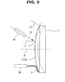
- a coating solution 3 is sprayed parallel to the axial direction of the substrate 1 to the lens surface 2 having a large curvature, droplets of the coating solution 3 are adhered to the lens surface 2 at the peripheral portion of the lens surface 2 while flowing toward the peripheral edge, as indicated by a chain double-dashed line in Fig. 9 .
- the thickness of the coating solution 3 applied to the central portion of the lens surface 2 becomes smaller than that of the coating solution 3 applied at the peripheral portion.
- the coating solution 3 is obliquely applied to the lens surface 2 so that the coating solution 3 flows toward the center of the lens surface 2 to cancel the above-described problem.
- the coating direction of the coating solution 3 according to this embodiment is a direction toward a target coating position T on a side opposite to an axis C1 of the substrate 1 with respect to a normal L1 passing through the target coating position T of the lens surface 2, as shown in Fig. 9 .
- a center line C2 of a coating nozzle 26 according to this embodiment is almost parallel to a normal L2 at the peripheral edge of the lens surface 2 on a virtual plane including the axis C1 of the substrate 1 and the normal L1, as shown in Fig. 9 .
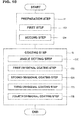
- Coating step S2 is executed by angle setting step S2E, and first to fourth divisional coating steps S2A to S2D, as shown in the flowchart of Fig. 10 .
- First to fourth divisional coating steps S2A to S2D are the same as the steps described in the second embodiment.
- Angle setting step S2E is a step of setting the coating direction of the coating nozzle 26 to be inclined with respect to the lens surface 2, as described above. By executing angle setting step S2E, the coating nozzle 26 is directed to the target coating position T from a side opposite to the axis C1 of the substrate 1 with respect to the normal L1 passing through the target coating position T of the lens surface 2.
- the coating solution 3 is applied to the entire lens surface 2 in first to fourth divisional coating steps S2A to S2D after setting the angle of the coating nozzle 26 in angle setting step S2E.
- first to fourth divisional coating steps S2A to S2D the coating solution 3 is obliquely applied toward the center of the lens surface 2, so the coating solution 3 applied to the lens surface 2 can be prevented from flowing toward the periphery of the lens surface 2.
- the coating solution 3 is not applied relatively thick to the peripheral portion of the lens surface 2 owing to dripping, and the film thickness distribution of the lens surface 2 is uniformed.
- the spray direction of the coating nozzle 26 may be changed in correspondence with the curvature of the target coating position T at the time of translation.
- the coating solution 3 can be applied so that the amount in which the coating solution 3 flows toward the center of the lens surface 2 becomes uniform. Therefore, the film thickness distribution is uniformed at high accuracy.
- This embodiment has described an example in which, when applying the coating solution 3 in coating step S2, the lens surface 2 is divided into a plurality of coating regions and the moving speed of the coating nozzle 26 is changed for the respective coating regions.
- a method for manufacturing an optical lens according to the present invention can execute a curing step after applying a coating solution to a lens surface, as shown in Figs. 11 and 12 .
- the same reference numerals as those described with reference to Figs. 1 to 10 denote the same parts, and a detailed description thereof will be omitted properly.
- a coating solution 3 which has been applied to a lens surface 2 of the substrate 1 to have a thickness of more than 10 ⁇ m, flows by its own weight, drips, and gathers to a lower portion (the peripheral portion of a convex curved surface 2a or the central portion of a concave curved surface 2b).
- the dripping occurs immediately after application of the coating solution 3 as long as the coating solution 3 is fluid, and continues until the drying or curing of the film proceeds and the coating solution 3 loses fluidity.
- the coating solution 3 is of a thermosetting type, if the temperature of the solution film rises during curing, the viscosity decreases and dripping occurs seriously. Even if the coating solution 3 can be applied thick to have a uniform thickness, dripping occurs at the time of curing and may finally lead to a film thickness failure.
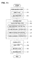
- a method for manufacturing an optical lens according to this embodiment includes curing step S3 that is performed under the same conditions as those of coating step S2 after coating step S2 of applying the coating solution 3 to the spectacle lens substrate 1, as shown in Fig. 11 .
- Curing step S3 is executed by first step S3A that satisfies the first condition, second step S3B that satisfies the second condition, and heating step S3C.
- Heating step S3C is executed by heating the coating solution 3 together with the substrate 1 while rotating the substrate 1 longitudinally at a predetermined rotational speed (about 15 to 50 RPM) in a state in which the first and second steps are executed, that is, a state in which the substrate 1 is inclined so that the angle of an axis C1 with respect to the horizontal direction falls within a predetermined angle range. Heating is performed until at least the fluidity of the coating solution 3 is lost.
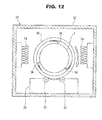
- Curing step S3 can be executed using, for example, a curing apparatus 31 shown in Fig. 12 .
- the curing apparatus 31 includes a curing vessel 32, and a rolling device 33 accommodated in the curing vessel 32.
- the curing vessel 32 includes a heater 34.
- the coating solution 3 is of an ultraviolet curing type
- the curing vessel 32 includes an ultraviolet lamp (not shown).
- the rolling device 33 is used to rotate the substrate 1 together with a holder 35.
- the holder 35 is formed into a cylindrical shape capable of accommodating the substrate 1.
- a plurality of clamp members 36 sandwich the peripheral surface of the substrate 1 and hold the substrate 1 on a single axis.
- the holder 35 is placed on two rollers 37 of the rolling device 33 in a state in which the holder 35 stands so that the axis is directed horizontally.
- the rollers 37 are driven by a motor (not shown) and rotate at a predetermined rotational speed in the same direction. Along with the rotation of the rollers 37, the substrate 1 rotates together with the holder 35. That is, the curing apparatus 31 can be used to heat the substrate 1 while rotating it longitudinally within the curing vessel 32, and cure the coating solution 3.
- heating step S3C is executed in a state in which the first and second conditions to execute coating step S2 are satisfied.
- the coating solution 3 can therefore be cured in a state in which the coating solution 3 does not flow in one direction by the gravity.
- the coating solution 3 is cured while maintaining a state in which the coating solution 3 is applied to have a uniform film thickness on the lens surface 2. Hence, a high-quality film is formed.
- this embodiment has described an example in which, when applying the coating solution 3 in coating step S2, the lens surface 2 is divided into a plurality of coating regions and the moving speed of a coating nozzle 26 is changed for the respective coating regions.
- the coating solution 3 is applied to either one of the convex curved surface 2a and concave curved surface 2b of the lens surfaces 2, and subsequently applied to the other one of the convex curved surface 2a and concave curved surface 2b of the lens surfaces 2. After that, the coating solution 3 applied to the two lens surfaces 2 is cured to a degree at which fluidity is lost. By employing this method, the coating solution 3 applied to the two, convex curved surface 2a and concave curved surface 2b can be cured efficiently.
- the method for manufacturing an optical lens according to the present invention is applicable when performing application of the coating solution 3 to the convex curved surface 2a, application of the coating solution 3 to the concave curved surface 2b, and curing of the coating solution 3 applied to the convex curved surface 2a and the concave curved surface 2b.
- the coating solution 3 is applied to either one of the convex curved surface 2a and concave curved surface 2b of the lens surfaces 2, and is cured to a degree at which fluidity is lost. After that, the coating solution 3 is applied to the other one of the convex curved surface 2a and concave curved surface 2b of the lens surfaces 2, and is cured. Even in this case, the present invention is applicable when performing application of the coating solution 3 to the respective lens surfaces 2 and curing of the coating solution 3 applied to the two lens surfaces 2.
- the implementation of the present invention is not limited to the method explained in each of the above-described embodiments, but can be appropriately changed.
- the above-described embodiments have explained an example in which a film such as a hard coat film or a photochronic film is formed on the spectacle lens substrate 1.
- the present invention is applicable to even another optical lens different from a spectacle lens.
- the lens was set in the lens holder, and rotated at a rotational speed of 50 rpm so that the axis of the lens became horizontal. While rotating the lens, a coating solution 3 was sprayed onto the concave and convex surfaces from the above-mentioned spray nozzle arranged on the optical axis of the lens. The spray nozzle moved from the peripheral portion to central portion of the lens at a constant speed of 30 mm/min, and sprayed the spray solution in a constant amount of 1.0 ml/min.
- the lens surfaces were heated to 50°C by panel heaters arranged on the two side surfaces of the lens while maintaining the lens angle and the rotational speed. The heating was performed for 2 min until the coating solution lost fluidity. Then, the lens was detached from the lens holder, and heated and cured in a thermosetting oven at 100°C for 1 h. The outer appearance of the coating film of the obtained lens was inspected, and film thicknesses at the central and peripheral portions of the lens were measured. The film thickness measurement was performed using a film thickness measurement system available from OptoSirius.
- Coating was performed following the same procedure as that in Example 1 except that, when moving the spray nozzle from the peripheral portion to central portion of a lens, an area was calculated for every area concentrically divided at a 5-mm pitch, and the moving speed was adjusted in accordance with the calculated area.
- Coating was performed by the same method as that in Example 2 except that, when coating the convex surface side of a lens, the nozzle was inclined toward the peripheral side at an angle of 30° with respect to the axis.
- Coating was performed by the same method as that in Example 2 except that a lens was rotated so that the axis of the lens became vertical (the lens was rotated horizontally).
- Coating was performed by the same method as that in Example 2 except that, when rotating a lens, the rotational speed was set to be 100 rpm.
- Coating was performed by the same method as that in Example 3 except that, when rotating a lens, the rotational speed was set to be 100 rpm.
Landscapes
- Physics & Mathematics (AREA)
- Engineering & Computer Science (AREA)
- Health & Medical Sciences (AREA)
- Ophthalmology & Optometry (AREA)
- General Physics & Mathematics (AREA)
- Optics & Photonics (AREA)
- Manufacturing & Machinery (AREA)
- Mechanical Engineering (AREA)
- General Health & Medical Sciences (AREA)
- Surface Treatment Of Optical Elements (AREA)
- Eyeglasses (AREA)
- Application Of Or Painting With Fluid Materials (AREA)
Abstract
Description
- The present invention relates to a method for manufacturing an optical lens, in which a coating solution is applied to an optical lens substrate while the optical lens substrate is rotated longitudinally.
- A plastic spectacle lens, which is one of optical lenses, is provided with performance requested of the spectacle lens by performing various coating processes on its surface. These coating processes include a primer process, a process of forming a hard coat film, and a process of forming an antireflection film.
- A primer film formed by the primer process has a function of adding performance including shock resistance, adhesion, and crack mitigation using softness. A hard coat film needs to be very hard in order to improve scratch resistance. An outermost layer serving as the outer surface of the hard coat film is provided with an antireflection film. By arranging the antireflection film on the outermost layer, performance including the antireflection function, durability, and scratch resistance is further added.
- A primer layer at the time of the primer process and a hard coat layer serving as a hard coat film are formed by applying a coating solution to a lens surface. As a method of applying a coating solution to a lens surface, there are a dipping method, a spin coat method, a spray coat method, and an inkjet method as disclosed in
patent literature 1. Application of a coating solution by the inkjet method disclosed inpatent literature 1 is performed so that a spectacle lens substrate is rotated in a state in which the lens surface is directed vertically to uniform the film thickness on the entire lens surface. - The film thickness is uniformed by dividing the lens surface into a plurality of concentric coating regions, and adjusting the amount of coating solution for the respective coating regions.
- On the lens surface of a spectacle lens, interference fringes sometimes appear in a state in which various above-mentioned films are formed. It is known that the interference fringes are reduced by forming a thick hard coat film.
- Patent Literature 1: Japanese Patent Laid-Open No.
2004-122115 - The present inventor considers formation of a thicker hard coat film in order to improve the scratch resistance of a spectacle lens and reduce the generation of interference fringes mentioned above. However, it is difficult for the conventional dipping method and spin coat method to apply, to the lens surface, a coating solution for forming a hard coat film so as to have a thickness of 5 µm or more.
- In contrast, the spray coat method and inkjet method can apply the coating solution to have a thickness of 10 µm or more. However, when the coating solution was applied by the coating or the inkjet method to have a thickness of much more than 10 µm, a new problem in which the film thickness distribution became nonuniform arose. The cause of the nonuniform thickness distribution is considered to be so-called "dripping" because lens surfaces are formed from convex and concave curved surfaces.
- Dripping is a phenomenon in which a coating film gradually flows by its own weight and gathers on the lower side of a curvature surface (the peripheral portion of a convex curved surface or the central portion of a concave curved surface). The dripping can be suppressed to a certain degree by reducing the fluidity of the coating solution. However, if the coating solution is less fluid, the film surface is formed not smoothly but into a so-called "orange peel surface".
- It is an object of the present invention to provide a method for manufacturing an optical lens, in which a coating solution having normal fluidity can be applied thick to a lens surface without causing dripping.
- To achieve this object, according to the present invention, there is provided a method for manufacturing an optical lens, comprising the steps of as a first coating condition, setting an angle of an axis of an optical lens substrate with respect to a horizontal direction within a predetermined angle range with reference to a convex surface side, as a second coating condition, rotating the optical lens substrate around the axis at a predetermined rotational speed at which a coating solution on a lens surface of the optical lens substrate is held in a coating position, and when the first coating condition and the second coating condition are satisfied, applying the coating solution to the lens surface of the optical lens substrate, the rotating step including a step of rotating the optical lens substrate within, as the predetermined angle range, a range between a maximum inclination angle of the axis at which a peripheral edge of the lens surface is positioned at the highest position of the lens surface of the optical lens substrate, and a maximum inclination angle of the axis at which the peripheral edge of the lens surface is positioned at the lowest position of the lens surface of the optical lens substrate.
- According to the present invention, the direction of gravity acting on a coating solution adhered to an optical lens substrate alternately changes between the central direction and peripheral direction of a lens along with rotation of the optical lens substrate. For this reason, the coating solution adhered to the rotating optical lens substrate does not flow in one direction though it is fluid. Since the influence of gravity, which is a prime factor of "dripping", can be canceled by longitudinal rotation of the optical lens substrate, "dripping" of the coating solution flowing along the lens surface does not occur. The present invention can therefore provide a method for manufacturing an optical lens, in which a coating solution having normal fluidity can be applied thick to a lens surface without causing dripping.
-
-
Fig. 1 is a sectional view showing a spectacle lens substrate on which a hard coat film is formed by a method for manufacturing a spectacle lens according to the first embodiment; -
Fig. 2 is a flowchart for explaining the method for manufacturing a spectacle lens according to the first embodiment; -
Fig. 3 is a side view showing the spectacle lens substrate inclined so that a convex curved surface is directed obliquely upward; -
Fig. 4 is a side view showing the spectacle lens substrate inclined so that the convex curved surface is directed obliquely downward; -
Fig. 5 is a side view showing a rotating apparatus; -
Fig. 6 is a side view showing the rotating apparatus, and a coating apparatus that executes a coating step; -
Fig. 7 is a front view showing a lens surface for explaining a plurality of coating regions according to the second embodiment; -
Fig. 8 is a flowchart for explaining a method for manufacturing a spectacle lens according to the second embodiment; -
Fig. 9 is a side view showing a spectacle lens substrate and a coating nozzle for explaining the coating direction according to the third embodiment; -
Fig. 10 is a flowchart for explaining a method for manufacturing a spectacle lens according to the third embodiment; -
Fig. 11 is a flowchart for explaining a method for manufacturing a spectacle lens according to the fourth embodiment; and -
Fig. 12 is a sectional view showing a curing apparatus that executes a curing step. - An embodiment of a method for manufacturing an optical lens according to the present invention will now be described in detail with reference to
Figs. 1 to 6 . A form in which the present invention is applied to a spectacle lens will be explained here. - A method for manufacturing a spectacle lens according to this embodiment is a method for longitudinally rotating a
spectacle lens substrate 1 shown inFig. 1 , and applying acoating solution 3 to a lens surface 2 (a convexcurved surface 2a and a concavecurved surface 2b). For convenience, thecoating solution 3 shown inFig. 1 is illustrated to be thicker than it really is. The method for manufacturing a spectacle lens is executed by preparation step S1 and coating step S2, as shown in the flowchart ofFig. 2 . - Preparation step S1 is a step for satisfying conditions (coating solution application conditions) for applying the
coating solution 3. The coating solution application conditions are made up of first step S1A for satisfying the first condition to be described later, and second step S1B for satisfying the second condition to be described later. - The first condition is satisfied when the angle of an axis C1 of the
spectacle lens substrate 1 with respect to the horizontal direction falls within a predetermined angle range, as shown inFigs. 3 and 4 . The predetermined angle range is a range between an angle θ1 shown inFig. 3 and an angle θ2 shown inFig. 4 . The angle θ1 shown inFig. 3 is the maximum inclination angle of the axis C1 when thespectacle lens substrate 1 is inclined clockwise inFig. 3 (direction in which thelens surface 2 formed from the convexcurved surface 2a is directed upward) from a state in which the axis C1 is horizontal, so as to keep a state in which a peripheral edge P of thelens surface 2 is positioned at the highest position H of thelens surface 2. - The angle θ2 shown in
Fig. 4 is the maximum inclination angle of the axis C1 when thespectacle lens substrate 1 is inclined counterclockwise inFig. 4 (direction in which thelens surface 2 formed from the convexcurved surface 2a is directed downward) from a state in which the axis is horizontal, so as to keep a state in which the peripheral edge P of thelens surface 2 is positioned at the lowest position L of thelens surface 2. - The second condition is satisfied by rotating the
spectacle lens substrate 1 around the axis C1 at a predetermined rotational speed. To rotate theoptical lens substrate 1 at the predetermined rotational speed in a state in which the first condition is satisfied, thesubstrate 1 is held by arotating apparatus 11, as shown inFig. 5 . Therotating apparatus 11 includes a support table 12, arotation driving unit 14 that is supported by the support table 12 pivotally via ahorizontal support shaft 13, and aholder 16 attached to arotation shaft 15 of therotation driving unit 14. - The
rotation driving unit 14 is inclined with respect to the support table 12 about thesupport shaft 13 so that thesubstrate 1 is inclined at a desired angle. Therotation driving unit 14 rotates therotation shaft 15 at a predetermined constant rotational speed. The rotational speed can be, for example, about 15 to 50 RPM in correspondence with the fluidity of thecoating solution 3. Note that the rotational speed of therotation shaft 15 is not limited to the above-mentioned range. When thecoating solution 3 is highly fluid, the rotational speed is set to be relatively low. The rotational speed is set to be a speed at which thecoating solution 3 does not flow toward the periphery of thelens surface 2 by the centrifugal force. Theholder 16 holds thesubstrate 1. Theholder 16 sandwiches the peripheral surface of thesubstrate 1 by a plurality of clamp members, and holds thesubstrate 1 on the same axis as therotation shaft 15, details of which are not illustrated. - Coating step S2 is a step of applying the
coating solution 3 to thelens surface 2 of thesubstrate 1. Thecoating solution 3 is applied to thesubstrate 1 by acoating apparatus 21 shown inFig. 6 . Thecoating apparatus 21 includes asupport member 22, and acoating unit 24 that is supported by thesupport member 22 pivotally via ahorizontal support shaft 23. Thecoating unit 24 supports acoating nozzle 26 via atranslation mechanism 25. Thecoating nozzle 26 ejects thecoating solution 3, and is driven to move in the radial direction of thesubstrate 1 by thetranslation mechanism 25. - The ejection direction of the
coating solution 3 can be changed appropriately by inclining thecoating unit 24 with respect to thesupport member 22. More specifically, when the axis C1 of thesubstrate 1 is not horizontal and is inclined with respect to the horizontal direction, thecoating unit 24 is inclined with respect to thesupport member 22 so as to eject thecoating solution 3 with reference to the axis C1 of thesubstrate 1. - The
coating solution 3 is a general fluid coating solution such as a coating solution for forming a hard coat film or a coating solution for forming a photochronic film. Thecoating solution 3 is supplied from a supply device (not shown) to thecoating nozzle 26. - The
coating nozzle 26 according to this embodiment ejects small droplets of thecoating solution 3 in a constant ejection amount by the spray coat method. The range where thecoating nozzle 26 applies thecoating solution 3 is narrower than thelens surface 2. Thecoating nozzle 26 is moved in the radial direction of thesubstrate 1 by thetranslation mechanism 25 in a state in which thecoating solution 3 is sprayed to thelens surface 2. - That is, the
coating solution 3 can be applied to theentire lens surface 2 by moving, in the radial direction of thesubstrate 1, the range where thecoating nozzle 26 applies thecoating solution 3 in a state in which thesubstrate 1 rotates. Although not shown, a coating nozzle that ejects aliquid coating solution 3 can be used as thecoating nozzle 26. - The
translation mechanism 25 is configured to be able to change the moving speed in accordance with the position of thecoating nozzle 26. When thecoating nozzle 26 faces the peripheral portion of thesubstrate 1, the moving speed of thecoating nozzle 26 becomes lower than that when thecoating nozzle 26 faces the central portion of thesubstrate 1. - When executing the method for manufacturing a spectacle lens according to this embodiment, first, preparation step S1 is executed. In preparation step S1, the
substrate 1 is mounted on therotating apparatus 11 and is stood to set the axis C1 at a predetermined inclination angle. Then, thesubstrate 1 is rotated at a predetermined rotational speed. Thesubstrate 1 is stood so that the axis C1 becomes horizontal and thelens surface 2 extends vertically, as shown in, for example,Fig. 5 . Thesubstrate 1 is driven to rotate at the predetermined rotational speed by the rotatingapparatus 11. - Then, coating step S2 is executed. In coating step S2, as shown in
Fig. 6 , thecoating nozzle 26 is caused to face the convexcurved surface 2a or concavecurved surface 2b of thelens surface 2 in a state in which thesubstrate 1 rotates longitudinally, as described above. Thecoating nozzle 26 ejects thecoating solution 3. In this embodiment, droplets of thecoating solution 3 are ejected parallel to the axis C1 of thesubstrate 1 from thecoating nozzle 26, and sprayed to thelens surface 2. Thecoating nozzle 26 according to this embodiment is driven to translate in the radial direction of thesubstrate 1 from the peripheral portion to central portion of thelens surface 2 by thetranslation mechanism 25. - Hence, the
coating solution 3 is sequentially applied to thesubstrate 1 during rotation from the peripheral portion toward the central portion. The appliedcoating solution 3 rotates together with thesubstrate 1. The direction of gravity acting on thecoating solution 3 adhered to thesubstrate 1 alternately changes between the central direction and peripheral direction of the lens along with rotation of thesubstrate 1. Since the direction in which the gravity acts is not constant, thecoating solution 3 does not flow in one direction and stays at the adhesion position though it is fluid. Since the influence of gravity, which is a prime factor of "dripping", can be canceled by longitudinal rotation of thespectacle lens substrate 1, "dripping" of thecoating solution 3 flowing along thelens surface 2 does not occur. - According to this embodiment, therefore, the
coating solution 3 having normal fluidity can be applied thick to thelens surface 2 without causing dripping. According to this embodiment, in coating step S2, a layer of thecoating solution 3 with a thickness of at least 10 µm could be formed to have a uniform thickness on theentire lens surface 2. When a coating solution for forming a hard coat film is used as thecoating solution 3, a hard coat film is formed on thesubstrate 1 at a film thickness of at least 10 µm. A spectacle lens having a hard coat film of such a thickness is much higher in scratch resistance than a conventional spectacle lens. In addition, interference fringes are reduced. - Note that the
coating apparatus 21 shown inFig. 6 is so illustrated that thecoating nozzle 26 moves from top to bottom, but the present invention is not limited to this. That is, the same effects as those described above can be obtained even when thecoating nozzle 26 moves from the lower end side to upper side (center side) of thelens surface 2 or thecoating nozzle 26 moves horizontally. - Coating step S2 ends after rotation of the
substrate 1 continues by a predetermined time while maintaining a state in which the first and second conditions are satisfied even after the end of applying thecoating solution 3. The time during which rotation of thesubstrate 1 continues is the time by which the fluidity of thecoating solution 3 is lost to a degree at which thecoating solution 3 applied to thesubstrate 1 does not move on thesubstrate 1. Acoating solution 3 containing a volatile solvent increases in viscosity and decreases in fluidity when part of the solvent evaporates after application. An ultravioletcuring coating solution 3 increases in viscosity and decreases in fluidity upon irradiation with ultraviolet rays contained in the illumination in a coating environment. That is, in this embodiment, rotation of thesubstrate 1 stops after the fluidity of thecoating solution 3 becomes low so that thecoating solution 3 does not move on thesubstrate 1. Thus, the next step, for example, a curing step for curing thecoating solution 3 can be executed in a state in which thecoating solution 3 applied thick is held on thesubstrate 1 and so-called "dripping" does not occur. - This embodiment has described an example in which coating step S2 ends by stopping rotation of the
substrate 1 after the fluidity of thecoating solution 3 decreases. However, coating step S2 can be ended in a state in which thesubstrate 1 rotates. In this case, coating step S2 ends in a state in which thesubstrate 1 rotates, and the next step (for example, curing step) is executed in this state. This method can be implemented by, for example, moving therotating apparatus 11 between thecoating apparatus 21, and a curing apparatus (not shown) including a heater or ultraviolet lamp for curing thecoating solution 3. More specifically, thesubstrate 1 is transferred from thecoating apparatus 21 to the curing apparatus while it is driven to rotate by the rotatingapparatus 11. - A coating solution can be applied by changing settings for respective coating regions, as shown in
Figs. 7 and8 . In this embodiment, the same reference numerals as those described with reference toFigs. 1 to 6 denote the same parts, and a detailed description thereof will be omitted properly.Fig. 7 is a front view showing a lens surface for explaining another embodiment of coating step S2.Fig. 8 is a flowchart for explaining a method for manufacturing a spectacle lens according to this embodiment. The method for manufacturing a spectacle lens according to this embodiment is a method constituting an invention described inclaim 2. - The method for manufacturing a spectacle lens according to this embodiment is executed by, for example, preparation step S1, and coating step S2 including first to fourth divisional coating steps S2A to S2D to be described later, as shown in, for example,
Fig. 8 . - Coating step S2 is performed by changing a parameter regarding coating for respective coating regions #A to #D shown in
Fig. 7 . When applying acoating solution 3 in the respective coating regions #A to #D, thecoating solution 3 is applied by the same method as that when the first embodiment is adopted. More specifically, acoating nozzle 26 sprays droplets of thecoating solution 3 in a predetermined amount to a target coating position at part of alens surface 2. In addition, the target coating position is moved in the radial direction of thelens surface 2. Thecoating nozzle 26 according to this embodiment translates from the periphery to center of the lens surface 2 (a convexcurved surface 2a or a concavecurved surface 2b). - In this embodiment, the parameter which is changed in regard to coating is the moving speed of the
coating nozzle 26. This moving speed is set for the respective coating regions #A to #D shown inFig. 7 . The plurality of coating regions #A to #D shown inFig. 7 are formed by dividing a radius r from a center O to periphery of thelens surface 2 by every predetermined interval, and dividing thelens surface 2 by circles passing through the respective division points. The center of each circle passing through each division point coincides with the center of thelens surface 2. That is, the coating regions #A to #D are formed by dividing thelens surface 2 into a plurality of concentric circles. - The moving speed of the
coating nozzle 26 is set based on the areas of the coating regions #A to #D. The moving speed decreases as the area increases. That is, the moving speed becomes lowest when thecoating solution 3 is applied to the first coating region #A including the peripheral edge of thelens surface 2, and increases when thecoating solution 3 is applied to the second coating region #B positioned inside the first coating region #A in the radial direction. For this reason, the moving speed becomes higher when coating the third coating region #C than when coating the second coating region #B, and higher when coating the fourth coating region #D than when coating the third coating region #C. - As shown in
Fig. 8 , coating step S2 according to this embodiment is executed by first to fourth divisional coating steps S2A to S2D. First divisional coating step S2A is a step of applying thecoating solution 3 to the first coating region #A positioned on the outermost peripheral side out of the first to fourth coating regions #A to #D. The moving speed of thecoating nozzle 26 at this time is set to be a speed (lowest speed) corresponding to the area of the first coating region #A. - After the end of application up to the inner peripheral end of the first coating region #A, the
coating solution 3 is applied to the second coating region #B in second divisional coating step S2B. After applying thecoating solution 3 to the second coating region #B, the process advances from third divisional coating step S2C to fourth divisional coating step S2D. Thecoating nozzle 26 moves at moving speeds corresponding to areas to apply thecoating solution 3 to even the third and fourth coating regions #C and #D. - According to this embodiment, the
coating solution 3 is applied in coating step S2 so that the adhesion amount of thecoating solution 3 per unit area becomes a predetermined amount on theentire lens surface 2. Thecoating solution 3 can therefore be applied to have a uniform film thickness on theentire lens surface 2. In particular, the adhesion amount of thecoating solution 3 can be controlled based on the area of thelens surface 2, so the control of the adhesion amount can be simplified. In this embodiment, when dividing thelens surface 2 into the plurality of coating regions #A to #D, the radius of thelens surface 2 is divided at equal intervals, and thelens surface 2 is divided by circles passing through the division points. Thus, the areas of the coating regions #A to #D can be calculated easily. - Note that the above-described "parameter that is changed in regard to coating" is not limited to the moving speed of the
coating nozzle 26, and may be, for example, the ejection amount of thecoating solution 3 ejected from thecoating nozzle 26 or both the moving speed and ejection amount. When changing the ejection amount of thecoating solution 3, for example, the moving speed of thecoating nozzle 26 is kept constant, and the ejection amount of thecoating solution 3 is maximized at the time of coating the first coating region #A. In this case, when applying thecoating solution 3 to the second to fourth coating regions #B to #D, the ejection amount of thecoating solution 3 is desirably decreased in the order named. - The direction in which a coating solution is applied in a coating step can be a direction inclined with respect to the axis of a substrate. This embodiment will be described in detail with reference to
Figs. 9 and10 . InFigs. 9 and10 , the same reference numerals as those described with reference toFigs. 1 to 8 denote the same parts, and a detailed description thereof will be omitted properly. - In a
substrate 1 shown inFig. 9 , the curvature of a lens surface 2 (a convexcurved surface 2a) relatively increases. When acoating solution 3 is sprayed parallel to the axial direction of thesubstrate 1 to thelens surface 2 having a large curvature, droplets of thecoating solution 3 are adhered to thelens surface 2 at the peripheral portion of thelens surface 2 while flowing toward the peripheral edge, as indicated by a chain double-dashed line inFig. 9 . As a result, the thickness of thecoating solution 3 applied to the central portion of thelens surface 2 becomes smaller than that of thecoating solution 3 applied at the peripheral portion. - In this embodiment, the
coating solution 3 is obliquely applied to thelens surface 2 so that thecoating solution 3 flows toward the center of thelens surface 2 to cancel the above-described problem. The coating direction of thecoating solution 3 according to this embodiment is a direction toward a target coating position T on a side opposite to an axis C1 of thesubstrate 1 with respect to a normal L1 passing through the target coating position T of thelens surface 2, as shown inFig. 9 . A center line C2 of acoating nozzle 26 according to this embodiment is almost parallel to a normal L2 at the peripheral edge of thelens surface 2 on a virtual plane including the axis C1 of thesubstrate 1 and the normal L1, as shown inFig. 9 . - Coating step S2 according to this embodiment is executed by angle setting step S2E, and first to fourth divisional coating steps S2A to S2D, as shown in the flowchart of
Fig. 10 . First to fourth divisional coating steps S2A to S2D are the same as the steps described in the second embodiment. Angle setting step S2E is a step of setting the coating direction of thecoating nozzle 26 to be inclined with respect to thelens surface 2, as described above. By executing angle setting step S2E, thecoating nozzle 26 is directed to the target coating position T from a side opposite to the axis C1 of thesubstrate 1 with respect to the normal L1 passing through the target coating position T of thelens surface 2. - In coating step S2, the
coating solution 3 is applied to theentire lens surface 2 in first to fourth divisional coating steps S2A to S2D after setting the angle of thecoating nozzle 26 in angle setting step S2E. In first to fourth divisional coating steps S2A to S2D, thecoating solution 3 is obliquely applied toward the center of thelens surface 2, so thecoating solution 3 applied to thelens surface 2 can be prevented from flowing toward the periphery of thelens surface 2. - According to this embodiment, the
coating solution 3 is not applied relatively thick to the peripheral portion of thelens surface 2 owing to dripping, and the film thickness distribution of thelens surface 2 is uniformed. Note that the spray direction of thecoating nozzle 26 may be changed in correspondence with the curvature of the target coating position T at the time of translation. With this arrangement, thecoating solution 3 can be applied so that the amount in which thecoating solution 3 flows toward the center of thelens surface 2 becomes uniform. Therefore, the film thickness distribution is uniformed at high accuracy. - This embodiment has described an example in which, when applying the
coating solution 3 in coating step S2, thelens surface 2 is divided into a plurality of coating regions and the moving speed of thecoating nozzle 26 is changed for the respective coating regions. However, it is also possible to keep a constant moving speed of thecoating nozzle 26 throughout all coating regions, change the ejection amount of thecoating solution 3 for the respective coating regions, and apply thecoating solution 3. - A method for manufacturing an optical lens according to the present invention can execute a curing step after applying a coating solution to a lens surface, as shown in
Figs. 11 and12 . InFigs. 11 and12 , the same reference numerals as those described with reference toFigs. 1 to 10 denote the same parts, and a detailed description thereof will be omitted properly. - When a
spectacle lens substrate 1 is placed horizontally, acoating solution 3, which has been applied to alens surface 2 of thesubstrate 1 to have a thickness of more than 10 µm, flows by its own weight, drips, and gathers to a lower portion (the peripheral portion of a convexcurved surface 2a or the central portion of a concavecurved surface 2b). The dripping occurs immediately after application of thecoating solution 3 as long as thecoating solution 3 is fluid, and continues until the drying or curing of the film proceeds and thecoating solution 3 loses fluidity. When thecoating solution 3 is of a thermosetting type, if the temperature of the solution film rises during curing, the viscosity decreases and dripping occurs seriously. Even if thecoating solution 3 can be applied thick to have a uniform thickness, dripping occurs at the time of curing and may finally lead to a film thickness failure. - A method for manufacturing an optical lens according to this embodiment includes curing step S3 that is performed under the same conditions as those of coating step S2 after coating step S2 of applying the
coating solution 3 to thespectacle lens substrate 1, as shown inFig. 11 . Curing step S3 is executed by first step S3A that satisfies the first condition, second step S3B that satisfies the second condition, and heating step S3C. Heating step S3C is executed by heating thecoating solution 3 together with thesubstrate 1 while rotating thesubstrate 1 longitudinally at a predetermined rotational speed (about 15 to 50 RPM) in a state in which the first and second steps are executed, that is, a state in which thesubstrate 1 is inclined so that the angle of an axis C1 with respect to the horizontal direction falls within a predetermined angle range. Heating is performed until at least the fluidity of thecoating solution 3 is lost. - Curing step S3 can be executed using, for example, a curing
apparatus 31 shown inFig. 12 . The curingapparatus 31 includes a curingvessel 32, and a rollingdevice 33 accommodated in the curingvessel 32. When thecoating solution 3 is of a thermosetting type, the curingvessel 32 includes aheater 34. When thecoating solution 3 is of an ultraviolet curing type, the curingvessel 32 includes an ultraviolet lamp (not shown). - The rolling
device 33 is used to rotate thesubstrate 1 together with aholder 35. Theholder 35 is formed into a cylindrical shape capable of accommodating thesubstrate 1. A plurality ofclamp members 36 sandwich the peripheral surface of thesubstrate 1 and hold thesubstrate 1 on a single axis. Theholder 35 is placed on tworollers 37 of the rollingdevice 33 in a state in which theholder 35 stands so that the axis is directed horizontally. - The
rollers 37 are driven by a motor (not shown) and rotate at a predetermined rotational speed in the same direction. Along with the rotation of therollers 37, thesubstrate 1 rotates together with theholder 35. That is, the curingapparatus 31 can be used to heat thesubstrate 1 while rotating it longitudinally within the curingvessel 32, and cure thecoating solution 3. - By the method for manufacturing a spectacle lens according to this embodiment, heating step S3C is executed in a state in which the first and second conditions to execute coating step S2 are satisfied. The
coating solution 3 can therefore be cured in a state in which thecoating solution 3 does not flow in one direction by the gravity. According to this embodiment, thecoating solution 3 is cured while maintaining a state in which thecoating solution 3 is applied to have a uniform film thickness on thelens surface 2. Hence, a high-quality film is formed. - Note that this embodiment has described an example in which, when applying the
coating solution 3 in coating step S2, thelens surface 2 is divided into a plurality of coating regions and the moving speed of acoating nozzle 26 is changed for the respective coating regions. However, it is also possible to keep a constant moving speed of thecoating nozzle 26 throughout all coating regions, change the ejection amount of thecoating solution 3 for the respective coating regions, and apply thecoating solution 3. - To form, for example, a hard coat film on the
spectacle lens substrate 1, thecoating solution 3 is applied to either one of the convexcurved surface 2a and concavecurved surface 2b of the lens surfaces 2, and subsequently applied to the other one of the convexcurved surface 2a and concavecurved surface 2b of the lens surfaces 2. After that, thecoating solution 3 applied to the twolens surfaces 2 is cured to a degree at which fluidity is lost. By employing this method, thecoating solution 3 applied to the two, convexcurved surface 2a and concavecurved surface 2b can be cured efficiently. Also, by employing this method, for example, when application of thecoating solution 3 to the convexcurved surface 2a has ended and thecoating solution 3 is applied to the concavecurved surface 2b, even if a droplet of thecoating solution 3 moves around to the convexcurved surface 2a and is adhered to the convexcurved surface 2a, this droplet is absorbed in a coating film on the convexcurved surface 2a, keeping a good outer appearance. The method for manufacturing an optical lens according to the present invention is applicable when performing application of thecoating solution 3 to the convexcurved surface 2a, application of thecoating solution 3 to the concavecurved surface 2b, and curing of thecoating solution 3 applied to the convexcurved surface 2a and the concavecurved surface 2b. - Application of the
coating solution 3 to the twolens surfaces 2, and curing of it can also be performed for everylens surface 2. In this case, thecoating solution 3 is applied to either one of the convexcurved surface 2a and concavecurved surface 2b of the lens surfaces 2, and is cured to a degree at which fluidity is lost. After that, thecoating solution 3 is applied to the other one of the convexcurved surface 2a and concavecurved surface 2b of the lens surfaces 2, and is cured. Even in this case, the present invention is applicable when performing application of thecoating solution 3 to therespective lens surfaces 2 and curing of thecoating solution 3 applied to the two lens surfaces 2. - Note that the implementation of the present invention is not limited to the method explained in each of the above-described embodiments, but can be appropriately changed. The above-described embodiments have explained an example in which a film such as a hard coat film or a photochronic film is formed on the
spectacle lens substrate 1. However, the present invention is applicable to even another optical lens different from a spectacle lens. - The present invention will be further explained by examples. However, the present invention is not limited to aspects described in the examples.
- As a solvent, 20 parts by mass of methanol were added to 17 parts by mass of an organosilicon compound "γ-glycidoxypropyl trimethoxysilane" (KBM-403 available from Shin-Etsu Chemical). After the solution was stirred for 10 min, 3.9 parts by mass of 0.1 mol/L hydrochloric acid were added as a hydrolysis catalyst and the resultant solution was stirred for 24 h. Then, 20 parts by mass of isopropyl alcohol and 44 parts by mass of methanol-dispersed colloidal silica (methanol silica-sol available from Nissan Chemical Industries) were added to the obtained solution, and the solution was stirred at room temperature for 10 min.
- After stirring for 10 min, 1 mass part of aluminum acetylacetonate and 0.1 mass part of a leveling agent (FZ-77 available from Dow Corning Tray) were added as a curing agent. The resultant solution was further stirred at room temperature for 48 h, preparing a coating solution for forming a hard coat. The viscosity of the obtained coating solution was 7 mPa·S (20°C).
- The coating solution prepared in "1." was applied to the surface of a plastic lens substrate by an ultrasonic atomizer available from Sono-Tek. Coating was performed on, as the lens substrate, the concave and convex surfaces of a plastic lens (trade name "New Looks 1.6"), available from HOYA, with a power of -2.0 D, a curvature radius R of the convex surface = 300 mm, and R of the concave surface = 150 mm.
- The lens was set in the lens holder, and rotated at a rotational speed of 50 rpm so that the axis of the lens became horizontal. While rotating the lens, a
coating solution 3 was sprayed onto the concave and convex surfaces from the above-mentioned spray nozzle arranged on the optical axis of the lens. The spray nozzle moved from the peripheral portion to central portion of the lens at a constant speed of 30 mm/min, and sprayed the spray solution in a constant amount of 1.0 ml/min. - After coating, the lens surfaces were heated to 50°C by panel heaters arranged on the two side surfaces of the lens while maintaining the lens angle and the rotational speed. The heating was performed for 2 min until the coating solution lost fluidity. Then, the lens was detached from the lens holder, and heated and cured in a thermosetting oven at 100°C for 1 h. The outer appearance of the coating film of the obtained lens was inspected, and film thicknesses at the central and peripheral portions of the lens were measured. The film thickness measurement was performed using a film thickness measurement system available from OptoSirius.
- Coating was performed following the same procedure as that in Example 1 except that, when moving the spray nozzle from the peripheral portion to central portion of a lens, an area was calculated for every area concentrically divided at a 5-mm pitch, and the moving speed was adjusted in accordance with the calculated area.
- Coating was performed by the same method as that in Example 2 except that, when coating the convex surface side of a lens, the nozzle was inclined toward the peripheral side at an angle of 30° with respect to the axis.
- Coating was performed by the same method as that in Example 2 except that a lens was rotated so that the axis of the lens became vertical (the lens was rotated horizontally).
- Coating was performed by the same method as that in Example 2 except that, when rotating a lens, the rotational speed was set to be 100 rpm.
- Coating was performed by the same method as that in Example 3 except that, when rotating a lens, the rotational speed was set to be 100 rpm.
- In Examples 1 to 3 and Comparative Examples 1 to 3, the presence/absence of dripping and an orange peel surface on a convex surface, and the presence/absence of dripping and an orange peel surface on a concave surface were visually checked, and the film thickness of the convex surface and that of the concave surface were measured, obtaining results as shown in Table 1 below. As the results of the visual check in Table 1, ⊚ represents "absent", ○ represents "almost absent", Δ represents "slightly present", and X represents "remarkably present".
[Table 1] No. Results Dripping on Convex Surface Dripping on Concave Surface Orange Peel Surface on Convex Surface Orange Peel Surface on Concave Surface Film Thickness of Film Thickness of Convex Surface (µm) Concave Surface (µm) Central Portion Peripheral Portion Central Portion Peripheral Portion Comparative Example 1 ○ ○ Δ Δ 16 11 18 10 Example 1 ○ ⊚ ○ ⊚ 15 20 19 21 Example 2 ⊚ - ⊚ - 20 19 - - Example 3 × × Δ Δ 12 20 27 13 Comparative Example 2 × Δ Δ ○ 12 23 16 25 Comparative Example 3 × - ○ - 15 23 - - - 1... spectacle lens substrate, 2...lens surface, 2a...convex curved surface, 2b...concave curved surface, θ1, θ2...angle, H...high position, P...peripheral edge, T...target coating position, L1...normal
Claims (4)
- A method for manufacturing an optical lens, comprising the steps of:as a first coating condition, setting an angle of an axis of an optical lens substrate with respect to a horizontal direction within a predetermined angle range with reference to a convex surface side;as a second coating condition, rotating the optical lens substrate around the axis at a predetermined rotational speed at which a coating solution on a lens surface of the optical lens substrate is held in a coating position; andwhen the first coating condition and the second coating condition are satisfied, coating the lens surface of the optical lens substrate with the coating solution,the rotating step including a step of rotating the optical lens substrate within, as the predetermined angle range, a range between a maximum inclination angle of the axis at which a peripheral edge of the lens surface is positioned at the highest position of the lens surface of the optical lens substrate, and a maximum inclination angle of the axis at which the peripheral edge of the lens surface is positioned at the lowest position of the lens surface of the optical lens substrate.
- The method for manufacturing an optical lens according to claim 1, wherein the coating step includes a step of spraying a droplet of the coating solution to a target coating position moving between a peripheral portion and central portion of the lens surface so as to set an adhesion amount of the coating solution per unit area to be a predetermined amount on the entire lens surface of the optical lens substrate.
- The method for manufacturing an optical lens according to claim 2, wherein the coating step includes a step of, when applying a droplet of the coating solution to a lens surface formed from a convex curved surface, applying the droplet of the coating solution in a direction toward the target coating position on a side opposite to the axis of the optical lens substrate with respect to a normal passing through the target coating position of the lens surface of the optical lens substrate.
- The method for manufacturing an optical lens according to claim 1, further comprising a step of curing the coating solution on the lens surface of the optical lens in a state in which the first condition and the second condition are satisfied after applying the coating solution to the lens surface of the optical lens substrate.
Applications Claiming Priority (2)
| Application Number | Priority Date | Filing Date | Title |
|---|---|---|---|
| JP2012191868 | 2012-08-31 | ||
| PCT/JP2013/073501 WO2014034926A1 (en) | 2012-08-31 | 2013-09-02 | Method for manufacturing optical lens |
Publications (2)
| Publication Number | Publication Date |
|---|---|
| EP2891905A1 true EP2891905A1 (en) | 2015-07-08 |
| EP2891905A4 EP2891905A4 (en) | 2016-05-25 |
Family
ID=50183724
Family Applications (1)
| Application Number | Title | Priority Date | Filing Date |
|---|---|---|---|
| EP13832606.1A Withdrawn EP2891905A4 (en) | 2012-08-31 | 2013-09-02 | Method for manufacturing optical lens |
Country Status (4)
| Country | Link |
|---|---|
| US (1) | US20150198746A1 (en) |
| EP (1) | EP2891905A4 (en) |
| JP (1) | JPWO2014034926A1 (en) |
| WO (1) | WO2014034926A1 (en) |
Cited By (1)
| Publication number | Priority date | Publication date | Assignee | Title |
|---|---|---|---|---|
| CN113385397A (en) * | 2021-06-21 | 2021-09-14 | 杭州美迪凯光电科技股份有限公司 | Coating process integrating dispensing and spin coating of lens film |
Families Citing this family (5)
| Publication number | Priority date | Publication date | Assignee | Title |
|---|---|---|---|---|
| US20180224329A1 (en) * | 2017-02-09 | 2018-08-09 | Corning Incorporated | Probe based rolling optic hyperspectral data collection system |
| WO2021039292A1 (en) * | 2019-08-30 | 2021-03-04 | 京セラ株式会社 | Coating device, coating film, and coating method |
| BR112023023167A2 (en) * | 2021-05-07 | 2024-01-30 | Essilor Int | LENS COATING METHOD WITH LENSLETS WITH IMPROVED CONTROL ON POWER DISPLACEMENT |
| CN113231274A (en) * | 2021-06-04 | 2021-08-10 | 浙江美迪凯光学半导体有限公司 | Spraying process of lens film |
| CN117406314A (en) * | 2023-12-01 | 2024-01-16 | 华中光电技术研究所(中国船舶集团有限公司第七一七研究所) | A method for coating polished flat protective paint on spherical components |
Family Cites Families (12)
| Publication number | Priority date | Publication date | Assignee | Title |
|---|---|---|---|---|
| FR2551383B1 (en) * | 1983-09-02 | 1986-07-04 | Essilor Int | METHOD AND DEVICE FOR SURFACING AN OPTICAL LENS WITH A SURFACE (S) OF REVOLUTION |
| FR2551382B1 (en) * | 1983-09-02 | 1986-05-16 | Essilor Int | METHOD AND DEVICE FOR SURFACING AN OPTICAL LENS |
| JPH06246220A (en) * | 1993-02-23 | 1994-09-06 | Seiko Epson Corp | Surface treatment method and surface treatment apparatus |
| JPH09173946A (en) * | 1995-12-22 | 1997-07-08 | Pioneer Electron Corp | Spin coating device |
| US6352747B1 (en) * | 1999-03-31 | 2002-03-05 | Ppg Industries Ohio, Inc. | Spin and spray coating process for curved surfaces |
| JP2001264514A (en) * | 2000-03-22 | 2001-09-26 | Ricoh Opt Ind Co Ltd | Optical film forming device, method for forming lens and lens |
| JP2001327908A (en) * | 2000-05-23 | 2001-11-27 | Seiko Epson Corp | Liquid coating method, smoothing method, optical member manufacturing method using the same, and optical member processing apparatus |
| JP3979353B2 (en) | 2002-08-02 | 2007-09-19 | セイコーエプソン株式会社 | Application method |
| JP4346359B2 (en) * | 2003-06-26 | 2009-10-21 | 株式会社トクヤマ | Spin coat equipment |
| FI20070131L (en) * | 2007-02-14 | 2008-08-15 | Olavi Matti Kalervo Nieminen | A new method for manufacturing optical products |
| JP5513720B2 (en) * | 2008-05-29 | 2014-06-04 | Hoya株式会社 | Manufacturing method of plastic lens |
| JP2009101354A (en) * | 2008-12-01 | 2009-05-14 | Seiko Epson Corp | Optical member manufacturing equipment |
-
2013
- 2013-09-02 JP JP2014533148A patent/JPWO2014034926A1/en active Pending
- 2013-09-02 US US14/423,930 patent/US20150198746A1/en not_active Abandoned
- 2013-09-02 EP EP13832606.1A patent/EP2891905A4/en not_active Withdrawn
- 2013-09-02 WO PCT/JP2013/073501 patent/WO2014034926A1/en not_active Ceased
Cited By (1)
| Publication number | Priority date | Publication date | Assignee | Title |
|---|---|---|---|---|
| CN113385397A (en) * | 2021-06-21 | 2021-09-14 | 杭州美迪凯光电科技股份有限公司 | Coating process integrating dispensing and spin coating of lens film |
Also Published As
| Publication number | Publication date |
|---|---|
| EP2891905A4 (en) | 2016-05-25 |
| US20150198746A1 (en) | 2015-07-16 |
| JPWO2014034926A1 (en) | 2016-08-08 |
| WO2014034926A1 (en) | 2014-03-06 |
Similar Documents
| Publication | Publication Date | Title |
|---|---|---|
| US20150198746A1 (en) | Method for manufacturing optical lens | |
| US8613982B2 (en) | Method of producing coated lenses | |
| JP4229853B2 (en) | Application method and spectacle lens manufacturing method | |
| CN106179815B (en) | A kind of spraying method of spraying machine | |
| US9664820B2 (en) | Method for manufacturing optical lens | |
| US20110203519A1 (en) | Method and apparatus for forming optical film, and optical article | |
| CN100573198C (en) | Coating device | |
| CN104096656A (en) | Coating Device And Coating Method | |
| WO2005075109A1 (en) | Coating method and production method for dimming lens | |
| EP2775340A1 (en) | Spectacle lens and method for producing same | |
| US20020127347A1 (en) | Method and apparatus for producing coated plate | |
| WO2007052815A1 (en) | Coater | |
| US10442053B2 (en) | Method for handling a lens | |
| JPWO2009028351A1 (en) | Method for forming a coating film on the surface of a plastic lens | |
| CN101291741B (en) | Method for removing mixed air in coating liquid and apparatus therefor | |
| CN101157074A (en) | Method and device for forming optical film and optical article | |
| EP4334122B1 (en) | Method for coating lenses with lenslets with an improved control on power shift | |
| CN117358475A (en) | Automatic oiling machine and oiling method for inner surface of bearing outer ring | |
| CN111708259B (en) | Tackifying unit of spin coating developing machine | |
| US11260418B2 (en) | Method for manufacturing target object coated with coating substance | |
| JP7500905B2 (en) | Method and system for applying non-Newtonian fluids - Patents.com | |
| JPH1120037A (en) | Thin film forming apparatus, thin film forming method, and method of manufacturing composite lens using the same | |
| JP2007185608A (en) | Method of producing functional coating film formed glass base material | |
| JP2025132792A5 (en) | ||
| CN121911621A (en) | Spraying process of acrylic polyurethane hammer paint on shell |
Legal Events
| Date | Code | Title | Description |
|---|---|---|---|
| PUAI | Public reference made under article 153(3) epc to a published international application that has entered the european phase |
Free format text: ORIGINAL CODE: 0009012 |
|
| 17P | Request for examination filed |
Effective date: 20150331 |
|
| AK | Designated contracting states |
Kind code of ref document: A1 Designated state(s): AL AT BE BG CH CY CZ DE DK EE ES FI FR GB GR HR HU IE IS IT LI LT LU LV MC MK MT NL NO PL PT RO RS SE SI SK SM TR |
|
| AX | Request for extension of the european patent |
Extension state: BA ME |
|
| DAX | Request for extension of the european patent (deleted) | ||
| RA4 | Supplementary search report drawn up and despatched (corrected) |
Effective date: 20160422 |
|
| RIC1 | Information provided on ipc code assigned before grant |
Ipc: G02B 1/10 20060101AFI20160418BHEP Ipc: G02C 7/02 20060101ALI20160418BHEP Ipc: B29D 11/00 20060101ALI20160418BHEP Ipc: G02B 1/11 20150101ALI20160418BHEP Ipc: B05D 1/40 20060101ALI20160418BHEP |
|
| STAA | Information on the status of an ep patent application or granted ep patent |
Free format text: STATUS: THE APPLICATION HAS BEEN WITHDRAWN |
|
| 18W | Application withdrawn |
Effective date: 20190919 |