EP2891894A2 - Magnetic sensor - Google Patents
Magnetic sensor Download PDFInfo
- Publication number
- EP2891894A2 EP2891894A2 EP14192867.1A EP14192867A EP2891894A2 EP 2891894 A2 EP2891894 A2 EP 2891894A2 EP 14192867 A EP14192867 A EP 14192867A EP 2891894 A2 EP2891894 A2 EP 2891894A2
- Authority
- EP
- European Patent Office
- Prior art keywords
- magnetic
- detection element
- magnet
- generating means
- magnetic field
- Prior art date
- Legal status (The legal status is an assumption and is not a legal conclusion. Google has not performed a legal analysis and makes no representation as to the accuracy of the status listed.)
- Withdrawn
Links
- 238000001514 detection method Methods 0.000 claims abstract description 58
- 239000006247 magnetic powder Substances 0.000 claims abstract description 5
- 230000000149 penetrating effect Effects 0.000 claims description 3
- 230000004907 flux Effects 0.000 description 43
- 238000005259 measurement Methods 0.000 description 20
- 238000010586 diagram Methods 0.000 description 16
- 239000013598 vector Substances 0.000 description 11
- 239000000758 substrate Substances 0.000 description 7
- 238000001739 density measurement Methods 0.000 description 6
- 230000000694 effects Effects 0.000 description 4
- 230000005415 magnetization Effects 0.000 description 3
- 230000007423 decrease Effects 0.000 description 1
- 230000014509 gene expression Effects 0.000 description 1
- 238000000034 method Methods 0.000 description 1
- 230000006641 stabilisation Effects 0.000 description 1
- 238000011105 stabilization Methods 0.000 description 1
Images




Classifications
-
- G—PHYSICS
- G07—CHECKING-DEVICES
- G07D—HANDLING OF COINS OR VALUABLE PAPERS, e.g. TESTING, SORTING BY DENOMINATIONS, COUNTING, DISPENSING, CHANGING OR DEPOSITING
- G07D7/00—Testing specially adapted to determine the identity or genuineness of valuable papers or for segregating those which are unacceptable, e.g. banknotes that are alien to a currency
- G07D7/04—Testing magnetic properties of the materials thereof, e.g. by detection of magnetic imprint
-
- G—PHYSICS
- G01—MEASURING; TESTING
- G01N—INVESTIGATING OR ANALYSING MATERIALS BY DETERMINING THEIR CHEMICAL OR PHYSICAL PROPERTIES
- G01N27/00—Investigating or analysing materials by the use of electric, electrochemical, or magnetic means
- G01N27/72—Investigating or analysing materials by the use of electric, electrochemical, or magnetic means by investigating magnetic variables
-
- G—PHYSICS
- G01—MEASURING; TESTING
- G01R—MEASURING ELECTRIC VARIABLES; MEASURING MAGNETIC VARIABLES
- G01R33/00—Arrangements or instruments for measuring magnetic variables
- G01R33/02—Measuring direction or magnitude of magnetic fields or magnetic flux
- G01R33/06—Measuring direction or magnitude of magnetic fields or magnetic flux using galvano-magnetic devices
-
- G—PHYSICS
- G01—MEASURING; TESTING
- G01R—MEASURING ELECTRIC VARIABLES; MEASURING MAGNETIC VARIABLES
- G01R33/00—Arrangements or instruments for measuring magnetic variables
- G01R33/12—Measuring magnetic properties of articles or specimens of solids or fluids
- G01R33/1215—Measuring magnetisation; Particular magnetometers therefor
-
- G—PHYSICS
- G01—MEASURING; TESTING
- G01R—MEASURING ELECTRIC VARIABLES; MEASURING MAGNETIC VARIABLES
- G01R33/00—Arrangements or instruments for measuring magnetic variables
- G01R33/02—Measuring direction or magnitude of magnetic fields or magnetic flux
- G01R33/06—Measuring direction or magnitude of magnetic fields or magnetic flux using galvano-magnetic devices
- G01R33/07—Hall effect devices
-
- G—PHYSICS
- G01—MEASURING; TESTING
- G01R—MEASURING ELECTRIC VARIABLES; MEASURING MAGNETIC VARIABLES
- G01R33/00—Arrangements or instruments for measuring magnetic variables
- G01R33/02—Measuring direction or magnitude of magnetic fields or magnetic flux
- G01R33/06—Measuring direction or magnitude of magnetic fields or magnetic flux using galvano-magnetic devices
- G01R33/09—Magnetoresistive devices
Definitions
- the present invention relates to a magnetic sensor preferably used for a paper money identification device, for example.
- the paper money identification device includes a magnetic sensor reading magnetic ink printed on paper money.
- the magnetic sensor has a magnet and a magnetic detection element disposed above a magnetic pole face of the magnet and detects magnetic variation associated with passage of paper money.
- the present invention was conceived in view of the situations and it is therefore an object of the present invention to provide a magnetic sensor capable of suppressing output variation due to flapping of an object to be identified as compared to a conventional one.
- a magnetic sensor comprises:
- a magnetic field at a magnetic sensitive point of the magnetic detection element may increase in at least a portion of the medium, when the medium moves away from the magnetic detection element in the magnetic pole direction.
- the bias magnetic field generating means may include two magnets, and the two magnets are arranged side by side across a gap and both have the same magnetic pole as a magnetic pole closer to the magnetic detection element.
- the bias magnetic field generating means may include a hollow magnet having a through-hole penetrating therethrough in the magnetic pole direction, and the hollow magnet has the same magnetic pole on an entire end surface closer to the magnetic detection element.
- the bias magnetic field generating means includes a magnet and two yokes disposed on one magnetic pole face of the magnet, and the two yokes are arranged side by side across a gap.
- a magnetic sensor can be provided which is capable of suppressing output variation due to flapping of an object to be identified as compared to a conventional one.
- Fig. 1 is a schematic plan view of a magnetic sensor according to a first embodiment of the present invention.
- Fig. 2 is a schematic front view thereof. These figures define three orthogonal directions, i.e., an x-direction, a y-direction, and a z-direction.
- the magnetic sensor of this embodiment includes a hollow magnet 1 as a bias magnetic field generating means, a substrate 2, and a magnetic detection element 3.
- the hollow magnet 1 is in a tube shape having a through-hole 1a penetrating therethrough in the z-direction and is a circular tube magnet in this embodiment.
- a magnetic pole direction (magnetization direction) of the hollow magnet 1 is the z-direction and an end surface of the hollow magnet 1 on the positive side in the z-direction is entirely an N-pole while an end surface on the negative side in the z-direction is entirely an S-pole.
- the substrate 2 is disposed (fixed) onto the N-pole side end surface of the hollow magnet 1.
- the magnetic detection element 3 is mounted on the substrate 2.
- the magnetic detection element 3 is a Hall element or a magneto-resistance effect element (MR element) and is disposed such that variation in a magnetic field component in the x-direction can be detected.
- a magnetic sensitive point 3a of the magnetic detection element 3 is located on a center axis of the hollow magnet 1 (on a center axis of the through-hole 1a) .
- Paper money 4 to be identified is carried in the x-direction by a carrying system not depicted and passes across the magnetic detection element 3 on the positive side in the z-direction (the side opposite to the hollow magnet 1).
- Fig. 3 is a simulated view of magnetic fluxes generated by the hollow magnet 1 of Figs. 1 and 2 and visually illustrates magnetic fluxes on a plane including the center axis of the hollow magnet 1 and parallel to the x-z plane.
- Fig. 4 is a characteristic diagram of relationship between magnetic flux density generated by the hollow magnet 1 and distance. The result depicted in Fig. 4 is based on a size of the hollow magnet 1 having an outer diameter of 10 mm, an inner diameter of 3 mm, and a height of 5 mm.
- a distance indicted by the horizontal axis is a distance from the center of an N-pole side opening of the through-hole 1a of the hollow magnet 1 to a magnetic flux density measurement point.
- the magnetic flux density measurement point ranges to a position at a distance of 4 mm from the center of the N-pole side opening of the through-hole 1a of the hollow magnet 1 on the positive side in the z-direction.
- the magnetic flux density increases in a range to a distance of about 0.2 to 1.5 mm from the center of the N-pole side opening of the through-hole 1a of the hollow magnet 1 as a distance from the center becomes larger.
- the magnetic flux density is made negative in a range equal to or less than 0.2 mm due to the effect of magnetic fluxes flowing from the N-pole through the through-hole 1a of the hollow magnet 1 to the S-pole as depicted in the simulated view of Fig. 3 .
- the magnetic flux density increases as the distance becomes larger not only on the center axis of the hollow magnet 1 but also in a certain region in the vicinity of the center axis.
- This embodiment is configured such that a passage region of the paper money 4 to be identified includes a specific region in which the magnetic flux density increases as a distance from the hollow magnet 1 and the magnetic detection element 3 becomes larger on the positive side in the z-direction.
- output reduction can be suppressed when the passage region of the paper money 4 slightly deviates to the positive side in the z-direction due to flapping of the paper money 4. This effect will be described later.
- Fig. 5 is a comparison diagram between a magnetic flux density vector B1 at the magnetic sensitive point 3a of the magnetic detection element 3 when a magnetic portion 4a of the paper money 4 is close to the magnetic detection element 3 and a magnetic flux density vector B2 at the magnetic sensitive point 3a of the magnetic detection element 3 when the magnetic portion 4a of the paper money 4 is distant from the magnetic detection element 3.
- the magnetic flux density vector B2 in the case of the distant magnetic portion 4a of the paper money 4 forms an angle closer to 90 degrees relative to the x-direction as compared to the magnetic flux density vector B1 in the case of the close magnetic portion 4a of the paper money 4.
- the magnetic flux density vector B2 in the case of the distant magnetic portion 4a of the paper money 4 is larger than the magnetic flux density vector B1 in the case of the close magnetic portion 4a of the paper money 4.
- the passage region of the paper money 4 includes the specific region in which the magnetic flux density increases as a distance from the hollow magnet 1 and the magnetic detection element 3 becomes larger on the positive side in the z-direction as described above.
- a width of reduction from an x-direction component (a magnetization direction component of the magnetic detection element 3) of the magnetic flux density vector B1 can be shortened in the x-direction component of the magnetic flux density vector B2 as compared to the conventional case.
- a portion of reduction in the x-direction component due to an angular difference between the magnetic flux density vectors B1, B2 can be offset by a difference in magnitude. Therefore, if the magnetic portion 4a of the paper money 4 becomes more distant, a reduction can be suppressed in the magnetization direction component of the magnetic flux density at the magnetic sensitive point 3a of the magnetic detection element 3, and variation in output voltage of the magnetic detection element 3 can be suppressed.
- Fig. 6 is a waveform diagram of output voltage of the magnetic sensor of the first embodiment when a measurement magnetic body is moved along a passage region of the paper money 4.
- the measurement magnetic body is a piece of paper printed with magnetic ink on the entire surface, for example.
- the horizontal axis of Fig. 6 indicates a center position of the measurement magnetic body in the x-direction and 0 m indicates a position immediately above the center of the N-pole side opening of the through-hole 1a of the hollow magnet 1.
- the magnetic sensor is designed such that the output voltage is 2.5 V when the x-component of the magnetic flux density is zero at the magnetic sensitive point 3a of the magnetic detection element 3.
- Fig. 6 is a waveform diagram of output voltage of the magnetic sensor of the first embodiment when a measurement magnetic body is moved along a passage region of the paper money 4.
- the measurement magnetic body is a piece of paper printed with magnetic ink on the entire surface, for example.
- the horizontal axis of Fig. 6 indicates a center position of the measurement magnetic
- a waveform indicated by a dashed-dotted line is the waveform when the passage region of the measurement magnetic body is at a distance of 0.1 mm from an upper end surface of the magnetic detection element 3 on the positive side in the z-direction (when a gap is 0.1 mm)
- a waveform indicated by a solid line is the waveform when the passage region of the measurement magnetic body is at a distance of 0.5 mm from the upper end surface of the magnetic detection element 3 on the positive side in the z-direction (when a gap is 0.5 mm).
- a difference in output voltage between the close and distant measurement magnetic bodies is generally within about 10 % in terms of a peak value (amplitude).
- Fig. 7 is a characteristic diagram of relationship between a distance (gap) in the z-direction from the upper end surface of the magnetic detection element 3 to the passage region of the measurement magnetic body and a peak value (amplitude) of the output voltage of the magnetic sensor of the first embodiment when the measurement magnetic body is moved along the passage region of the paper money 4.
- the output voltage indicated by the vertical axis is indicated in percentage and is 100% when the gap is 0.1 mm.
- the magnetic sensor of this embodiment is configured such that the passage region of the paper money 4 includes the specific region in which the magnetic flux density increases as a distance from the hollow magnet 1 and the magnetic detection element 3 becomes larger on the positive side in the z-direction, a reduction in sensor output voltage can be suppressed when the magnetic portion 4a of the paper money 4 moves away from the magnetic detection element 3 due to flapping of the paper money 4, and the output variation due to flapping of the paper money 4 can be suppressed.
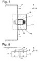
- Fig. 8 is a schematic plan view of a magnetic sensor according to a second embodiment of the present invention.
- Fig. 9 is a schematic front view thereof.
- the magnetic sensor of this embodiment is identical to the magnetic sensor of the first embodiment depicted in Figs. 1 and 2 except that a bias magnetic field generating means is made up of a first magnet 11 and a second magnet 12 and that the substrate 2 is disposed (fixed) onto the N-pole side end surfaces of both the first magnet 11 and the second magnet 12.
- the first magnet 11 and the second magnet 12 are rectangular column magnets of the same shape, for example, and are arranged side by side across a gap 13 in the x-direction and both have the N-pole on the end surfaces on the positive side in the z-direction.
- the magnetic sensitive point 3a of the magnetic detection element 3 is located on a virtual straight line passing through the center of the gap 13 in parallel with the z-direction.
- the first magnet 11 and the second magnet 12 arranged across the gap 13 are used as the bias magnetic field generating means to form a specific region in which the magnetic flux density increases as a distance from the first magnet 11 and the second magnet 12 as well as the magnetic detection element 3 becomes larger on the positive side in the z-direction as is the case with the first embodiment.
- Fig. 10 is a schematic front view of a magnetic sensor according to a third embodiment of the present invention.
- Fig. 11 is a perspective view of a bias magnetic field generating means of the magnetic sensor of Fig. 10 .
- the magnetic sensor of this embodiment is identical to the magnetic sensor of the first embodiment depicted in Figs. 1 and 2 except that the bias magnetic field generating means is made up of a magnet 20 as well as a first yoke 21 and a second yoke 22 and that the substrate 2 is disposed (fixed) onto the end surfaces of both the first yoke 21 and the second yoke 22 on the positive side in the z-direction.
- the magnet 20 is, for example, a rectangular column magnet and has the N-pole on the end surface on the positive side in the z-direction.
- the first yoke 21 and the second yoke 22 have the same rectangular column shape, for example, and are disposed (fixed) onto the N-pole side end surface of the magnet 20 and arranged side by side across a gap 23 in the x-direction.
- the magnetic sensitive point 3a of the magnetic detection element 3 is located on a virtual straight line connecting the center of the magnet 20 and the center of the gap 23.
- Fig. 12 is a simulated view of magnetic fluxes generated by the bias magnetic field generating means of Fig. 11 and visually illustrates magnetic fluxes on a plane including the center position of the magnetic 20 in the y-direction (depth direction) and parallel to the x-z plane.
- Fig. 13 is a characteristic diagram of relationship between magnetic flux density generated by the bias magnetic field generating means of Fig. 11 and distance. The result depicted in Fig.
- a distance indicted by the horizontal axis is a distance from an intersection between a virtual line passing through the center of the magnet 20 in parallel with the z-direction and a virtual plane including the end surfaces of the first yoke 21 and the second yoke 22 on the positive side in the z-direction to a magnetic flux density measurement point.
- the magnetic flux density measurement point ranges to a position at a distance of 4 mm from the intersection on the positive side in the z-direction.
- Fig. 13 it is understood that the magnetic flux density increases in a range within a distance of about 0.7 mm from the intersection as the distance from the intersection becomes larger. Therefore, as is the case with the first embodiment, this embodiment forms a specific region in which the magnetic flux density increases as a distance from the magnet 20, the first yoke 21, and the second yoke 22 as well as the magnetic detection element 3 increases on the positive side in the z-direction.
- Fig. 14 is a schematic plan view of a magnetic sensor of a comparison example.
- Fig. 15 is a schematic front view thereof.
- a bias magnetic field generating means is made up of one rectangular column magnet 80.
- the rectangular column magnet 80 has the N-pole on the entire end surface on the positive side in the z-direction and the S-pole on the entire end surface on the negative side in the z-direction.
- the substrate 2 is disposed (fixed) onto the N-pole side end surface of the rectangular column magnet 80.
- the magnetic detection element 3 is mounted on the substrate 2.
- the magnetic sensitive point 3a of the magnetic detection element 3 is located on a virtual line passing through the center of the rectangular column magnet 80 in parallel with the z-direction.
- Fig. 16 is a characteristic diagram of relationship between magnetic flux density generated by the rectangular column magnet 80 and distance related to the comparison example.
- the result depicted in Fig. 16 is based on a size of the rectangular column magnet having a width of 5 mm, a depth of 5 mm, and a height of 9 mm.
- a distance indicted by the horizontal axis is a distance from the center of the N-pole side end surface of the rectangular column magnet to a magnetic flux density measurement point.
- the magnetic flux density measurement point ranges to a position at a distance of 4 mm from the center of the N-pole side end surface of the rectangular column magnet.
- the magnetic flux density consistently decreases as the distance from the center of the N-pole side end surface becomes larger. In other words, in the case of the rectangular column magnet, the magnetic flux density does not increase in any range as the distance from the center of the N-pole side end surface becomes larger.
- Fig. 17 is a waveform diagram of output voltage of the magnetic sensor of the comparison example when the measurement magnetic body is moved along the passage region of the paper money 4.
- a waveform indicated by a dashed-dotted line is the waveform when the passage region of the measurement magnetic body is at a distance of 0.1 mm from the upper end surface of the magnetic detection element 3 on the positive side in the z-direction (when a gap is 0.1 mm)
- a waveform indicated by a solid line is the waveform when the passage region of the measurement magnetic body is at a distance of 0.5 mm from the upper end surface of the magnetic detection element 3 on the positive side in the z-direction (when a gap is 0.5 mm).
- a difference in output voltage between the close and distant measurement magnetic bodies is generally made larger to about 50 % in terms of a peak value (amplitude).
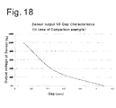
- Fig. 18 is a characteristic diagram of relationship between a distance (gap) in the z-direction from the upper end surface of the magnetic detection element 3 to the passage region of the measurement magnetic body and a peak value (amplitude) of the output voltage of the magnetic sensor of the comparison example when the measurement magnetic body is moved along the passage region of the paper money 4.
- the output voltage indicated by the vertical axis is indicated in percentage and is 100% when the gap is 0.1 mm. If the bias magnetic field generating means is the one rectangular column magnet 80, the output voltage is sharply reduced relative to gap expansion as depicted in Fig. 18 and the output voltage is reduced to half or less when a gap is 0.5 mm.
- the hollow magnet 1 of the first embodiment is not limited to a circular tube shape and may be in another tube shape such as a rectangular tube shape.
- the first magnet 11 and the second magnet 12 of the second embodiment as well as the magnet 20, the first yoke 21, and the second yoke 22 of the third embodiment are not limited to a rectangular column shape and may be another column shape (block shape) such as a circular column shape.
- the magnetic sensor is usable as a multichannel product by using a plurality of the magnetic sensors of the embodiments for covering a wider area.
- An obj ect to be identified by the magnetic sensor may be a magnetic powder adhered medium or a magnetic film adhered medium other than paper money.
Landscapes
- Physics & Mathematics (AREA)
- General Physics & Mathematics (AREA)
- Condensed Matter Physics & Semiconductors (AREA)
- Chemical & Material Sciences (AREA)
- Electrochemistry (AREA)
- Health & Medical Sciences (AREA)
- Life Sciences & Earth Sciences (AREA)
- Analytical Chemistry (AREA)
- Biochemistry (AREA)
- General Health & Medical Sciences (AREA)
- Immunology (AREA)
- Pathology (AREA)
- Chemical Kinetics & Catalysis (AREA)
- Measuring Magnetic Variables (AREA)
- Inspection Of Paper Currency And Valuable Securities (AREA)
- Investigating Or Analyzing Materials By The Use Of Magnetic Means (AREA)
Abstract
Description
- The present invention relates to a magnetic sensor preferably used for a paper money identification device, for example.
- Automatic vending machines etc. are disposed with a paper money identification device identifying input paper money. The paper money identification device includes a magnetic sensor reading magnetic ink printed on paper money. For example, as described in Japanese Laid-Open Patent Publication No.
63-155579 - Because of flapping during carrying of paper money, a distance between the magnetic pole face of the magnet and paper money slightly varies for each input and the output of the magnetic sensor varies each time even in the same type of paper money. From the viewpoint of output stabilization, such variations are preferably suppressed as small as possible. Such a problem commonly occurs even when a magnetic powder adhered medium or a magnetic film adhered medium other than paper money is identified.
- The present invention was conceived in view of the situations and it is therefore an object of the present invention to provide a magnetic sensor capable of suppressing output variation due to flapping of an object to be identified as compared to a conventional one.
- In the aspect of the present invention, a magnetic sensor comprises:
- a bias magnetic field generating means; and
- a magnetic detection element disposed on one side of the bias magnetic field generating means in a magnetic pole direction,
- the magnetic sensor identifying a medium, that is a magnetic powder adhered medium or a magnetic film adhered medium, passing across the magnetic detection element on the side opposite to the bias magnetic field generating means,
- the magnetic detection element being capable of detecting variation in a magnetic field component parallel to a movement direction of the medium to be identified,
- a passage region of the medium including a specific region in which a magnetic field increases when a distance from the magnetic detection element becomes larger in the magnetic pole direction.
- In the magnetic sensor, a magnetic field at a magnetic sensitive point of the magnetic detection element may increase in at least a portion of the medium, when the medium moves away from the magnetic detection element in the magnetic pole direction.
- In the magnetic sensor, the bias magnetic field generating means may include two magnets, and the two magnets are arranged side by side across a gap and both have the same magnetic pole as a magnetic pole closer to the magnetic detection element.
- In the magnetic sensor, the bias magnetic field generating means may include a hollow magnet having a through-hole penetrating therethrough in the magnetic pole direction, and the hollow magnet has the same magnetic pole on an entire end surface closer to the magnetic detection element.
- In the magnetic sensor, the bias magnetic field generating means includes a magnet and two yokes disposed on one magnetic pole face of the magnet, and the two yokes are arranged side by side across a gap.
- It is to be noted that any arbitrary combination of the above-described structural components as well as the expressions according to the present invention changed among a system and so forth are all effective as and encompassed by the present aspects.
- According to the aspects described above, a magnetic sensor can be provided which is capable of suppressing output variation due to flapping of an object to be identified as compared to a conventional one.
-
-
Fig. 1 is a schematic plan view of a magnetic sensor according to a first embodiment of the present invention. -
Fig. 2 is a schematic front view thereof. -
Fig. 3 is a simulated view of magnetic fluxes generated by ahollow magnet 1 ofFigs. 1 and 2 . -
Fig. 4 is a characteristic diagram of relationship between magnetic flux density generated by thehollow magnet 1 and distance. -
Fig. 5 is a comparison diagram related to a first embodiment between a magnetic flux density vector B1 at a magneticsensitive point 3a of amagnetic detection element 3 when amagnetic portion 4a ofpaper money 4 is close to themagnetic detection element 3 and a magnetic flux density vector B2 at the magneticsensitive point 3a of themagnetic detection element 3 when themagnetic portion 4a of thepaper money 4 is distant from themagnetic detection element 3. -
Fig. 6 is a waveform diagram of output voltage of the magnetic sensor of the first embodiment when a measurement magnetic body is moved along a passage region of thepaper money 4. -
Fig. 7 is a characteristic diagram of relationship between a distance (gap) in the z-direction from an upper end surface of themagnetic detection element 3 to a passage region of the measurement magnetic body and a peak value (amplitude) of the output voltage of the magnetic sensor of the first embodiment when the measurement magnetic body is moved along the passage region of thepaper money 4. -
Fig. 8 is a schematic plan view of a magnetic sensor according to a second embodiment of the present invention. -
Fig. 9 is a schematic front view thereof. -
Fig. 10 is a schematic front view of a magnetic sensor according to a third embodiment of the present invention. -
Fig. 11 is a perspective view of a bias magnetic field generating means of the magnetic sensor ofFig. 10 . -
Fig. 12 is a simulated view of magnetic fluxes generated by the bias magnetic field generating means ofFig. 11 . -
Fig. 13 is a characteristic diagram of relationship between magnetic flux density generated by the bias magnetic field generating means ofFig. 11 and distance. -
Fig. 14 is a schematic plan view of a magnetic sensor of a comparison example. -
Fig. 15 is a schematic front view thereof. -
Fig. 16 is a characteristic diagram of relationship between magnetic flux density generated by arectangular column magnet 80 and distance related to the comparison example. -
Fig. 17 is a waveform diagram of output voltage of the magnetic sensor of the comparison example when the measurement magnetic body is moved along the passage region of thepaper money 4. -
Fig. 18 is a characteristic diagram of relationship between a distance (gap) in the z-direction from the upper end surface of themagnetic detection element 3 to the passage region of the measurement magnetic body and a peak value (amplitude) of the output voltage of the magnetic sensor of the comparison example when the measurement magnetic body is moved along the passage region of thepaper money 4. - The invention will now be described based on the following embodiments which do not intend to limit the scope of the present invention but exemplify the invention. All of the features and the combinations thereof described in the embodiments are not necessarily essential to the invention.
-
Fig. 1 is a schematic plan view of a magnetic sensor according to a first embodiment of the present invention.Fig. 2 is a schematic front view thereof. These figures define three orthogonal directions, i.e., an x-direction, a y-direction, and a z-direction. The magnetic sensor of this embodiment includes ahollow magnet 1 as a bias magnetic field generating means, asubstrate 2, and amagnetic detection element 3. Thehollow magnet 1 is in a tube shape having a through-hole 1a penetrating therethrough in the z-direction and is a circular tube magnet in this embodiment. A magnetic pole direction (magnetization direction) of thehollow magnet 1 is the z-direction and an end surface of thehollow magnet 1 on the positive side in the z-direction is entirely an N-pole while an end surface on the negative side in the z-direction is entirely an S-pole. Thesubstrate 2 is disposed (fixed) onto the N-pole side end surface of thehollow magnet 1. Themagnetic detection element 3 is mounted on thesubstrate 2. Themagnetic detection element 3 is a Hall element or a magneto-resistance effect element (MR element) and is disposed such that variation in a magnetic field component in the x-direction can be detected. A magneticsensitive point 3a of themagnetic detection element 3 is located on a center axis of the hollow magnet 1 (on a center axis of the through-hole 1a) .Paper money 4 to be identified is carried in the x-direction by a carrying system not depicted and passes across themagnetic detection element 3 on the positive side in the z-direction (the side opposite to the hollow magnet 1). -
Fig. 3 is a simulated view of magnetic fluxes generated by thehollow magnet 1 ofFigs. 1 and 2 and visually illustrates magnetic fluxes on a plane including the center axis of thehollow magnet 1 and parallel to the x-z plane.Fig. 4 is a characteristic diagram of relationship between magnetic flux density generated by thehollow magnet 1 and distance. The result depicted inFig. 4 is based on a size of thehollow magnet 1 having an outer diameter of 10 mm, an inner diameter of 3 mm, and a height of 5 mm. InFig. 4 , a distance indicted by the horizontal axis is a distance from the center of an N-pole side opening of the through-hole 1a of thehollow magnet 1 to a magnetic flux density measurement point. The magnetic flux density measurement point ranges to a position at a distance of 4 mm from the center of the N-pole side opening of the through-hole 1a of thehollow magnet 1 on the positive side in the z-direction. - As depicted in
Fig. 4 , it is understood that the magnetic flux density increases in a range to a distance of about 0.2 to 1.5 mm from the center of the N-pole side opening of the through-hole 1a of thehollow magnet 1 as a distance from the center becomes larger. The magnetic flux density is made negative in a range equal to or less than 0.2 mm due to the effect of magnetic fluxes flowing from the N-pole through the through-hole 1a of thehollow magnet 1 to the S-pole as depicted in the simulated view ofFig. 3 . The magnetic flux density increases as the distance becomes larger not only on the center axis of thehollow magnet 1 but also in a certain region in the vicinity of the center axis. This embodiment is configured such that a passage region of thepaper money 4 to be identified includes a specific region in which the magnetic flux density increases as a distance from thehollow magnet 1 and themagnetic detection element 3 becomes larger on the positive side in the z-direction. As a result, output reduction can be suppressed when the passage region of thepaper money 4 slightly deviates to the positive side in the z-direction due to flapping of thepaper money 4. This effect will be described later. -
Fig. 5 is a comparison diagram between a magnetic flux density vector B1 at the magneticsensitive point 3a of themagnetic detection element 3 when amagnetic portion 4a of thepaper money 4 is close to themagnetic detection element 3 and a magnetic flux density vector B2 at the magneticsensitive point 3a of themagnetic detection element 3 when themagnetic portion 4a of thepaper money 4 is distant from themagnetic detection element 3. As depicted inFig. 5 , the magnetic flux density vector B2 in the case of the distantmagnetic portion 4a of thepaper money 4 forms an angle closer to 90 degrees relative to the x-direction as compared to the magnetic flux density vector B1 in the case of the closemagnetic portion 4a of thepaper money 4. On the other hand, the magnetic flux density vector B2 in the case of the distantmagnetic portion 4a of thepaper money 4 is larger than the magnetic flux density vector B1 in the case of the closemagnetic portion 4a of thepaper money 4. This is because the passage region of thepaper money 4 includes the specific region in which the magnetic flux density increases as a distance from thehollow magnet 1 and themagnetic detection element 3 becomes larger on the positive side in the z-direction as described above. As a result, a width of reduction from an x-direction component (a magnetization direction component of the magnetic detection element 3) of the magnetic flux density vector B1 can be shortened in the x-direction component of the magnetic flux density vector B2 as compared to the conventional case. For instance, a portion of reduction in the x-direction component due to an angular difference between the magnetic flux density vectors B1, B2 can be offset by a difference in magnitude. Therefore, if themagnetic portion 4a of thepaper money 4 becomes more distant, a reduction can be suppressed in the magnetization direction component of the magnetic flux density at the magneticsensitive point 3a of themagnetic detection element 3, and variation in output voltage of themagnetic detection element 3 can be suppressed. -
Fig. 6 is a waveform diagram of output voltage of the magnetic sensor of the first embodiment when a measurement magnetic body is moved along a passage region of thepaper money 4. The measurement magnetic body is a piece of paper printed with magnetic ink on the entire surface, for example. The horizontal axis ofFig. 6 indicates a center position of the measurement magnetic body in the x-direction and 0 m indicates a position immediately above the center of the N-pole side opening of the through-hole 1a of thehollow magnet 1. The magnetic sensor is designed such that the output voltage is 2.5 V when the x-component of the magnetic flux density is zero at the magneticsensitive point 3a of themagnetic detection element 3. InFig. 6 , a waveform indicated by a dashed-dotted line is the waveform when the passage region of the measurement magnetic body is at a distance of 0.1 mm from an upper end surface of themagnetic detection element 3 on the positive side in the z-direction (when a gap is 0.1 mm), and a waveform indicated by a solid line is the waveform when the passage region of the measurement magnetic body is at a distance of 0.5 mm from the upper end surface of themagnetic detection element 3 on the positive side in the z-direction (when a gap is 0.5 mm). As depicted inFig. 6 , a difference in output voltage between the close and distant measurement magnetic bodies is generally within about 10 % in terms of a peak value (amplitude). -
Fig. 7 is a characteristic diagram of relationship between a distance (gap) in the z-direction from the upper end surface of themagnetic detection element 3 to the passage region of the measurement magnetic body and a peak value (amplitude) of the output voltage of the magnetic sensor of the first embodiment when the measurement magnetic body is moved along the passage region of thepaper money 4. The output voltage indicated by the vertical axis is indicated in percentage and is 100% when the gap is 0.1 mm. By using thehollow magnet 1 as a bias magnetic field generating means, the output voltage is gradually reduced relative to gap expansion as depicted inFig. 7 and the reduction in the output voltage is made smaller even in a range to a gap of 0.5 mm. - Since the magnetic sensor of this embodiment is configured such that the passage region of the
paper money 4 includes the specific region in which the magnetic flux density increases as a distance from thehollow magnet 1 and themagnetic detection element 3 becomes larger on the positive side in the z-direction, a reduction in sensor output voltage can be suppressed when themagnetic portion 4a of thepaper money 4 moves away from themagnetic detection element 3 due to flapping of thepaper money 4, and the output variation due to flapping of thepaper money 4 can be suppressed. -
Fig. 8 is a schematic plan view of a magnetic sensor according to a second embodiment of the present invention.Fig. 9 is a schematic front view thereof. The magnetic sensor of this embodiment is identical to the magnetic sensor of the first embodiment depicted inFigs. 1 and 2 except that a bias magnetic field generating means is made up of afirst magnet 11 and asecond magnet 12 and that thesubstrate 2 is disposed (fixed) onto the N-pole side end surfaces of both thefirst magnet 11 and thesecond magnet 12. Thefirst magnet 11 and thesecond magnet 12 are rectangular column magnets of the same shape, for example, and are arranged side by side across agap 13 in the x-direction and both have the N-pole on the end surfaces on the positive side in the z-direction. The magneticsensitive point 3a of themagnetic detection element 3 is located on a virtual straight line passing through the center of thegap 13 in parallel with the z-direction. - In this embodiment, the
first magnet 11 and thesecond magnet 12 arranged across thegap 13 are used as the bias magnetic field generating means to form a specific region in which the magnetic flux density increases as a distance from thefirst magnet 11 and thesecond magnet 12 as well as themagnetic detection element 3 becomes larger on the positive side in the z-direction as is the case with the first embodiment. By including the specific region in the passage region of thepaper money 4, a reduction in sensor output voltage can be suppressed when the magnetic portion of thepaper money 4 moves away from themagnetic detection element 3 due to flapping of thepaper money 4, and the output variation due to flapping of thepaper money 4 can be suppressed, as is the case with the first embodiment. -
Fig. 10 is a schematic front view of a magnetic sensor according to a third embodiment of the present invention.Fig. 11 is a perspective view of a bias magnetic field generating means of the magnetic sensor ofFig. 10 . The magnetic sensor of this embodiment is identical to the magnetic sensor of the first embodiment depicted inFigs. 1 and 2 except that the bias magnetic field generating means is made up of amagnet 20 as well as afirst yoke 21 and asecond yoke 22 and that thesubstrate 2 is disposed (fixed) onto the end surfaces of both thefirst yoke 21 and thesecond yoke 22 on the positive side in the z-direction. Themagnet 20 is, for example, a rectangular column magnet and has the N-pole on the end surface on the positive side in the z-direction. Thefirst yoke 21 and thesecond yoke 22 have the same rectangular column shape, for example, and are disposed (fixed) onto the N-pole side end surface of themagnet 20 and arranged side by side across agap 23 in the x-direction. The magneticsensitive point 3a of themagnetic detection element 3 is located on a virtual straight line connecting the center of themagnet 20 and the center of thegap 23. -
Fig. 12 is a simulated view of magnetic fluxes generated by the bias magnetic field generating means ofFig. 11 and visually illustrates magnetic fluxes on a plane including the center position of the magnetic 20 in the y-direction (depth direction) and parallel to the x-z plane.Fig. 13 is a characteristic diagram of relationship between magnetic flux density generated by the bias magnetic field generating means ofFig. 11 and distance. The result depicted inFig. 13 is based on a size of themagnet 20 having a width of 5.0 mm, a depth of 5.0 mm, and a height of 3.0 mm and a size of the first andsecond yokes Fig. 13 , a distance indicted by the horizontal axis is a distance from an intersection between a virtual line passing through the center of themagnet 20 in parallel with the z-direction and a virtual plane including the end surfaces of thefirst yoke 21 and thesecond yoke 22 on the positive side in the z-direction to a magnetic flux density measurement point. The magnetic flux density measurement point ranges to a position at a distance of 4 mm from the intersection on the positive side in the z-direction. As depicted inFig. 13 , it is understood that the magnetic flux density increases in a range within a distance of about 0.7 mm from the intersection as the distance from the intersection becomes larger. Therefore, as is the case with the first embodiment, this embodiment forms a specific region in which the magnetic flux density increases as a distance from themagnet 20, thefirst yoke 21, and thesecond yoke 22 as well as themagnetic detection element 3 increases on the positive side in the z-direction. By including the specific region in the passage region of thepaper money 4, a reduction in sensor output voltage can be suppressed when the magnetic portion of thepaper money 4 moves away from themagnetic detection element 3 due to flapping of thepaper money 4, and the output variation due to flapping of thepaper money 4 can be suppressed, as is the case with the first embodiment. - A comparison example will be described for explaining the effect of the embodiments described above.
Fig. 14 is a schematic plan view of a magnetic sensor of a comparison example.Fig. 15 is a schematic front view thereof. In this comparison example, a bias magnetic field generating means is made up of onerectangular column magnet 80. Therectangular column magnet 80 has the N-pole on the entire end surface on the positive side in the z-direction and the S-pole on the entire end surface on the negative side in the z-direction. Thesubstrate 2 is disposed (fixed) onto the N-pole side end surface of therectangular column magnet 80. Themagnetic detection element 3 is mounted on thesubstrate 2. The magneticsensitive point 3a of themagnetic detection element 3 is located on a virtual line passing through the center of therectangular column magnet 80 in parallel with the z-direction. -
Fig. 16 is a characteristic diagram of relationship between magnetic flux density generated by therectangular column magnet 80 and distance related to the comparison example. The result depicted inFig. 16 is based on a size of the rectangular column magnet having a width of 5 mm, a depth of 5 mm, and a height of 9 mm. InFig. 16 , a distance indicted by the horizontal axis is a distance from the center of the N-pole side end surface of the rectangular column magnet to a magnetic flux density measurement point. The magnetic flux density measurement point ranges to a position at a distance of 4 mm from the center of the N-pole side end surface of the rectangular column magnet. As depicted inFig. 16 , in the case of the rectangular column magnet, the magnetic flux density consistently decreases as the distance from the center of the N-pole side end surface becomes larger. In other words, in the case of the rectangular column magnet, the magnetic flux density does not increase in any range as the distance from the center of the N-pole side end surface becomes larger. -
Fig. 17 is a waveform diagram of output voltage of the magnetic sensor of the comparison example when the measurement magnetic body is moved along the passage region of thepaper money 4. InFig. 17 , a waveform indicated by a dashed-dotted line is the waveform when the passage region of the measurement magnetic body is at a distance of 0.1 mm from the upper end surface of themagnetic detection element 3 on the positive side in the z-direction (when a gap is 0.1 mm), and a waveform indicated by a solid line is the waveform when the passage region of the measurement magnetic body is at a distance of 0.5 mm from the upper end surface of themagnetic detection element 3 on the positive side in the z-direction (when a gap is 0.5 mm). As depicted inFig. 17 , a difference in output voltage between the close and distant measurement magnetic bodies is generally made larger to about 50 % in terms of a peak value (amplitude). -
Fig. 18 is a characteristic diagram of relationship between a distance (gap) in the z-direction from the upper end surface of themagnetic detection element 3 to the passage region of the measurement magnetic body and a peak value (amplitude) of the output voltage of the magnetic sensor of the comparison example when the measurement magnetic body is moved along the passage region of thepaper money 4. The output voltage indicated by the vertical axis is indicated in percentage and is 100% when the gap is 0.1 mm. If the bias magnetic field generating means is the onerectangular column magnet 80, the output voltage is sharply reduced relative to gap expansion as depicted inFig. 18 and the output voltage is reduced to half or less when a gap is 0.5 mm. - Described above is an explanation based on the embodiment. The description of the embodiments is illustrative in nature and various variations in constituting elements and processes involved are possible. Those skilled in the art would readily appreciate that such variations are also within the scope of the present invention.
- The
hollow magnet 1 of the first embodiment is not limited to a circular tube shape and may be in another tube shape such as a rectangular tube shape. Thefirst magnet 11 and thesecond magnet 12 of the second embodiment as well as themagnet 20, thefirst yoke 21, and thesecond yoke 22 of the third embodiment are not limited to a rectangular column shape and may be another column shape (block shape) such as a circular column shape. The magnetic sensor is usable as a multichannel product by using a plurality of the magnetic sensors of the embodiments for covering a wider area. An obj ect to be identified by the magnetic sensor may be a magnetic powder adhered medium or a magnetic film adhered medium other than paper money.
Claims (5)
- A magnetic sensor comprising:a bias magnetic field generating means; anda magnetic detection element disposed on one side of the bias magnetic field generating means in a magnetic pole direction,the magnetic sensor identifying a medium, that is a magnetic powder adhered medium or a magnetic film adhered medium, passing across the magnetic detection element on the side opposite to the bias magnetic field generating means,the magnetic detection element being capable of detecting variation in a magnetic field component parallel to a movement direction of the medium to be identified,a passage region of the medium including a specific region in which a magnetic field increases when a distance from the magnetic detection element becomes larger in the magnetic pole direction.
- The magnetic sensor according to claim 1, wherein in at least a portion of the medium, a magnetic field at a magnetic sensitive point of the magnetic detection element increases when the medium moves away from the magnetic detection element in the magnetic pole direction.
- The magnetic sensor according to claim 1 or 2, wherein the bias magnetic field generating means includes two magnets, and the two magnets are arranged side by side across a gap and both have the same magnetic pole as a magnetic pole closer to the magnetic detection element.
- The magnetic sensor according to claim 1 or 2, wherein the bias magnetic field generating means includes a hollow magnet having a through-hole penetrating therethrough in the magnetic pole direction, and the hollow magnet has the same magnetic pole on an entire end surface closer to the magnetic detection element.
- The magnetic sensor according to claim 1 or 2, wherein the bias magnetic field generating means includes a magnet and two yokes disposed on one magnetic pole face of the magnet, and the two yokes are arranged side by side across a gap.
Applications Claiming Priority (1)
| Application Number | Priority Date | Filing Date | Title |
|---|---|---|---|
| JP2013246690A JP5858248B2 (en) | 2013-11-28 | 2013-11-28 | Magnetic sensor |
Publications (2)
| Publication Number | Publication Date |
|---|---|
| EP2891894A2 true EP2891894A2 (en) | 2015-07-08 |
| EP2891894A3 EP2891894A3 (en) | 2016-01-20 |
Family
ID=51900223
Family Applications (1)
| Application Number | Title | Priority Date | Filing Date |
|---|---|---|---|
| EP14192867.1A Withdrawn EP2891894A3 (en) | 2013-11-28 | 2014-11-12 | Magnetic sensor |
Country Status (4)
| Country | Link |
|---|---|
| US (1) | US20150145506A1 (en) |
| EP (1) | EP2891894A3 (en) |
| JP (1) | JP5858248B2 (en) |
| CN (1) | CN104680641A (en) |
Families Citing this family (8)
| Publication number | Priority date | Publication date | Assignee | Title |
|---|---|---|---|---|
| US9753114B2 (en) * | 2014-11-03 | 2017-09-05 | Honeywell Limited | Gap and displacement magnetic sensor system for scanner heads in paper machines or other systems |
| JP2017145441A (en) * | 2016-02-16 | 2017-08-24 | 日新製鋼株式会社 | Black surface coated high strength steel sheet and manufacturing method therefor |
| JP6877958B2 (en) * | 2016-11-10 | 2021-05-26 | 浜松光電株式会社 | Magnetic sensor |
| JP7119351B2 (en) * | 2017-11-24 | 2022-08-17 | Tdk株式会社 | magnetic sensor |
| US11493527B2 (en) * | 2020-10-21 | 2022-11-08 | Infineon Technologies Ag | Zero-gauss-magnet for differential, twist-insensitive magnetic speed sensors |
| JP2024090781A (en) * | 2022-12-23 | 2024-07-04 | ローム株式会社 | Magnetic detection device |
| JP2024094730A (en) * | 2022-12-28 | 2024-07-10 | ローム株式会社 | Magnetic detector |
| CN116818882B (en) * | 2023-07-03 | 2026-01-06 | 北京中唐电工程咨询有限公司 | Non-destructive testing sensors and non-destructive testing systems |
Citations (3)
| Publication number | Priority date | Publication date | Assignee | Title |
|---|---|---|---|---|
| JPS63154579A (en) | 1986-12-19 | 1988-06-27 | Hitachi Ltd | Paper handling device |
| US5814985A (en) * | 1994-09-16 | 1998-09-29 | Moving Magnet Technologies S.A. | Incremental sensor of speed and/or position for detecting low and null speeds |
| US6489872B1 (en) * | 1999-05-06 | 2002-12-03 | New Mexico Resonance | Unilateral magnet having a remote uniform field region for nuclear magnetic resonance |
Family Cites Families (9)
| Publication number | Priority date | Publication date | Assignee | Title |
|---|---|---|---|---|
| FR2388248A1 (en) * | 1977-04-20 | 1978-11-17 | Radiotechnique Compelec | HALL-EFFECT POSITION DETECTOR |
| JP3152085B2 (en) * | 1994-10-04 | 2001-04-03 | 株式会社村田製作所 | Magnetic sensor device |
| JPH10239338A (en) * | 1997-02-26 | 1998-09-11 | Mitsubishi Electric Corp | Detector |
| US7762380B2 (en) * | 2006-03-09 | 2010-07-27 | Cummins-Allison Corp. | Currency discrimination system and method |
| KR101427543B1 (en) * | 2010-07-30 | 2014-08-07 | 미쓰비시덴키 가부시키가이샤 | Magnetic substance detection device |
| DE102010035469A1 (en) * | 2010-08-26 | 2012-03-01 | Giesecke & Devrient Gmbh | Sensor of device for examination of value document e.g. check, has magnetoresistive element positioned such that field of magnet at magnetoresistive element is oriented perpendicular to sensitivity direction of magnetoresistive element |
| EP2816368B1 (en) * | 2012-02-13 | 2017-11-22 | Murata Manufacturing Co., Ltd. | Magnetic sensor apparatus |
| JP5877728B2 (en) * | 2012-02-16 | 2016-03-08 | グローリー株式会社 | Magnetic detector |
| CN102968845B (en) * | 2012-10-31 | 2015-11-25 | 江苏多维科技有限公司 | A kind of sensitive direction by magnetic bias is parallel to the currency examine magnetic head of detection faces |
-
2013
- 2013-11-28 JP JP2013246690A patent/JP5858248B2/en active Active
-
2014
- 2014-10-31 CN CN201410602571.2A patent/CN104680641A/en active Pending
- 2014-11-12 EP EP14192867.1A patent/EP2891894A3/en not_active Withdrawn
- 2014-11-13 US US14/540,095 patent/US20150145506A1/en not_active Abandoned
Patent Citations (3)
| Publication number | Priority date | Publication date | Assignee | Title |
|---|---|---|---|---|
| JPS63154579A (en) | 1986-12-19 | 1988-06-27 | Hitachi Ltd | Paper handling device |
| US5814985A (en) * | 1994-09-16 | 1998-09-29 | Moving Magnet Technologies S.A. | Incremental sensor of speed and/or position for detecting low and null speeds |
| US6489872B1 (en) * | 1999-05-06 | 2002-12-03 | New Mexico Resonance | Unilateral magnet having a remote uniform field region for nuclear magnetic resonance |
Also Published As
| Publication number | Publication date |
|---|---|
| CN104680641A (en) | 2015-06-03 |
| US20150145506A1 (en) | 2015-05-28 |
| JP5858248B2 (en) | 2016-02-10 |
| JP2015105835A (en) | 2015-06-08 |
| EP2891894A3 (en) | 2016-01-20 |
Similar Documents
| Publication | Publication Date | Title |
|---|---|---|
| US20150145506A1 (en) | Magnetic sensor | |
| JP5867235B2 (en) | Magnetic sensor device | |
| JP6300908B2 (en) | Magnetic sensor device | |
| WO2013153986A1 (en) | Magnetic sensor | |
| JP2009192261A (en) | Linear displacement detector | |
| EP3368863B1 (en) | Methods and apparatus for phase offset selection in ring magnet sensing | |
| US9645203B2 (en) | Magnetic field measuring device | |
| US9551764B2 (en) | Magnetic field measuring device | |
| JP5040658B2 (en) | Position detection apparatus, two-dimensional position measurement apparatus, optical instrument, and position detection method | |
| TWI684776B (en) | Magnetic sensor apparatus | |
| WO2016170885A1 (en) | Magnetic sensor device | |
| US11585676B2 (en) | Magnetic field measuring device | |
| JP2008286588A (en) | Position detection device | |
| US10215588B2 (en) | Position detecting device and structure for using position detecting device | |
| CN106461418A (en) | Magnetic position detection device | |
| JP2017049127A (en) | Magnetic field detection device and rotation detection device | |
| JP6075225B2 (en) | Magnetic sensor device | |
| JP2011169715A (en) | Position detection mechanism | |
| US10701267B2 (en) | Position detection device, control method, and storage medium | |
| US20100079134A1 (en) | Position detection apparatus using magnetoresistive effect element | |
| KR20210052555A (en) | Linear positioning system | |
| US11639974B1 (en) | Magnetic sensor device | |
| JP2021047036A (en) | Magnetic body detection sensor | |
| JP2012189527A (en) | Position detecting device | |
| WO2016117497A1 (en) | Displacement-detecting apparatus |
Legal Events
| Date | Code | Title | Description |
|---|---|---|---|
| PUAI | Public reference made under article 153(3) epc to a published international application that has entered the european phase |
Free format text: ORIGINAL CODE: 0009012 |
|
| 17P | Request for examination filed |
Effective date: 20141112 |
|
| AK | Designated contracting states |
Kind code of ref document: A2 Designated state(s): AL AT BE BG CH CY CZ DE DK EE ES FI FR GB GR HR HU IE IS IT LI LT LU LV MC MK MT NL NO PL PT RO RS SE SI SK SM TR |
|
| AX | Request for extension of the european patent |
Extension state: BA ME |
|
| PUAL | Search report despatched |
Free format text: ORIGINAL CODE: 0009013 |
|
| AK | Designated contracting states |
Kind code of ref document: A3 Designated state(s): AL AT BE BG CH CY CZ DE DK EE ES FI FR GB GR HR HU IE IS IT LI LT LU LV MC MK MT NL NO PL PT RO RS SE SI SK SM TR |
|
| AX | Request for extension of the european patent |
Extension state: BA ME |
|
| RIC1 | Information provided on ipc code assigned before grant |
Ipc: G01R 33/12 20060101AFI20151215BHEP Ipc: G01R 33/06 20060101ALI20151215BHEP Ipc: G07D 7/04 20160101ALI20151215BHEP Ipc: G01R 33/09 20060101ALN20151215BHEP Ipc: G01R 33/07 20060101ALN20151215BHEP |
|
| R17P | Request for examination filed (corrected) |
Effective date: 20160720 |
|
| RBV | Designated contracting states (corrected) |
Designated state(s): AL AT BE BG CH CY CZ DE DK EE ES FI FR GB GR HR HU IE IS IT LI LT LU LV MC MK MT NL NO PL PT RO RS SE SI SK SM TR |
|
| 17Q | First examination report despatched |
Effective date: 20190514 |
|
| STAA | Information on the status of an ep patent application or granted ep patent |
Free format text: STATUS: THE APPLICATION IS DEEMED TO BE WITHDRAWN |
|
| 18D | Application deemed to be withdrawn |
Effective date: 20190925 |