EP2891836A1 - Mechanical seal device - Google Patents
Mechanical seal device Download PDFInfo
- Publication number
- EP2891836A1 EP2891836A1 EP14764286.2A EP14764286A EP2891836A1 EP 2891836 A1 EP2891836 A1 EP 2891836A1 EP 14764286 A EP14764286 A EP 14764286A EP 2891836 A1 EP2891836 A1 EP 2891836A1
- Authority
- EP
- European Patent Office
- Prior art keywords
- seal ring
- seal
- static pressure
- stationary
- bellows
- Prior art date
- Legal status (The legal status is an assumption and is not a legal conclusion. Google has not performed a legal analysis and makes no representation as to the accuracy of the status listed.)
- Granted
Links
- 239000012530 fluid Substances 0.000 claims abstract description 100
- 230000003068 static effect Effects 0.000 claims abstract description 67
- 238000007789 sealing Methods 0.000 claims abstract description 28
- 239000007789 gas Substances 0.000 description 15
- 238000010926 purge Methods 0.000 description 14
- 239000007787 solid Substances 0.000 description 9
- 239000000463 material Substances 0.000 description 8
- 230000006866 deterioration Effects 0.000 description 4
- 125000006850 spacer group Chemical group 0.000 description 3
- 230000001360 synchronised effect Effects 0.000 description 3
- IJGRMHOSHXDMSA-UHFFFAOYSA-N Atomic nitrogen Chemical compound N#N IJGRMHOSHXDMSA-UHFFFAOYSA-N 0.000 description 1
- OKTJSMMVPCPJKN-UHFFFAOYSA-N Carbon Chemical compound [C] OKTJSMMVPCPJKN-UHFFFAOYSA-N 0.000 description 1
- 229920002943 EPDM rubber Polymers 0.000 description 1
- 229920000459 Nitrile rubber Polymers 0.000 description 1
- 229920006169 Perfluoroelastomer Polymers 0.000 description 1
- 229910052799 carbon Inorganic materials 0.000 description 1
- 229910001873 dinitrogen Inorganic materials 0.000 description 1
- 230000000694 effects Effects 0.000 description 1
- 229920006351 engineering plastic Polymers 0.000 description 1
- 229920001973 fluoroelastomer Polymers 0.000 description 1
- 235000013305 food Nutrition 0.000 description 1
- 239000007788 liquid Substances 0.000 description 1
- 238000004519 manufacturing process Methods 0.000 description 1
- 229940127554 medical product Drugs 0.000 description 1
- 229910001092 metal group alloy Inorganic materials 0.000 description 1
- 238000012986 modification Methods 0.000 description 1
- 230000004048 modification Effects 0.000 description 1
- HBMJWWWQQXIZIP-UHFFFAOYSA-N silicon carbide Chemical compound [Si+]#[C-] HBMJWWWQQXIZIP-UHFFFAOYSA-N 0.000 description 1
- 238000003756 stirring Methods 0.000 description 1
- 239000000126 substance Substances 0.000 description 1
- XLYOFNOQVPJJNP-UHFFFAOYSA-N water Substances O XLYOFNOQVPJJNP-UHFFFAOYSA-N 0.000 description 1
Images



Classifications
-
- F—MECHANICAL ENGINEERING; LIGHTING; HEATING; WEAPONS; BLASTING
- F16—ENGINEERING ELEMENTS AND UNITS; GENERAL MEASURES FOR PRODUCING AND MAINTAINING EFFECTIVE FUNCTIONING OF MACHINES OR INSTALLATIONS; THERMAL INSULATION IN GENERAL
- F16J—PISTONS; CYLINDERS; SEALINGS
- F16J15/00—Sealings
- F16J15/16—Sealings between relatively-moving surfaces
- F16J15/34—Sealings between relatively-moving surfaces with slip-ring pressed against a more or less radial face on one member
- F16J15/36—Sealings between relatively-moving surfaces with slip-ring pressed against a more or less radial face on one member connected by a diaphragm or bellow to the other member
-
- F—MECHANICAL ENGINEERING; LIGHTING; HEATING; WEAPONS; BLASTING
- F16—ENGINEERING ELEMENTS AND UNITS; GENERAL MEASURES FOR PRODUCING AND MAINTAINING EFFECTIVE FUNCTIONING OF MACHINES OR INSTALLATIONS; THERMAL INSULATION IN GENERAL
- F16J—PISTONS; CYLINDERS; SEALINGS
- F16J15/00—Sealings
- F16J15/16—Sealings between relatively-moving surfaces
- F16J15/34—Sealings between relatively-moving surfaces with slip-ring pressed against a more or less radial face on one member
- F16J15/3404—Sealings between relatively-moving surfaces with slip-ring pressed against a more or less radial face on one member and characterised by parts or details relating to lubrication, cooling or venting of the seal
- F16J15/3408—Sealings between relatively-moving surfaces with slip-ring pressed against a more or less radial face on one member and characterised by parts or details relating to lubrication, cooling or venting of the seal at least one ring having an uneven slipping surface
- F16J15/3412—Sealings between relatively-moving surfaces with slip-ring pressed against a more or less radial face on one member and characterised by parts or details relating to lubrication, cooling or venting of the seal at least one ring having an uneven slipping surface with cavities
- F16J15/342—Sealings between relatively-moving surfaces with slip-ring pressed against a more or less radial face on one member and characterised by parts or details relating to lubrication, cooling or venting of the seal at least one ring having an uneven slipping surface with cavities with means for feeding fluid directly to the face
-
- F—MECHANICAL ENGINEERING; LIGHTING; HEATING; WEAPONS; BLASTING
- F16—ENGINEERING ELEMENTS AND UNITS; GENERAL MEASURES FOR PRODUCING AND MAINTAINING EFFECTIVE FUNCTIONING OF MACHINES OR INSTALLATIONS; THERMAL INSULATION IN GENERAL
- F16J—PISTONS; CYLINDERS; SEALINGS
- F16J15/00—Sealings
- F16J15/16—Sealings between relatively-moving surfaces
- F16J15/34—Sealings between relatively-moving surfaces with slip-ring pressed against a more or less radial face on one member
- F16J15/3404—Sealings between relatively-moving surfaces with slip-ring pressed against a more or less radial face on one member and characterised by parts or details relating to lubrication, cooling or venting of the seal
- F16J15/3408—Sealings between relatively-moving surfaces with slip-ring pressed against a more or less radial face on one member and characterised by parts or details relating to lubrication, cooling or venting of the seal at least one ring having an uneven slipping surface
-
- F—MECHANICAL ENGINEERING; LIGHTING; HEATING; WEAPONS; BLASTING
- F16—ENGINEERING ELEMENTS AND UNITS; GENERAL MEASURES FOR PRODUCING AND MAINTAINING EFFECTIVE FUNCTIONING OF MACHINES OR INSTALLATIONS; THERMAL INSULATION IN GENERAL
- F16J—PISTONS; CYLINDERS; SEALINGS
- F16J15/00—Sealings
- F16J15/16—Sealings between relatively-moving surfaces
- F16J15/34—Sealings between relatively-moving surfaces with slip-ring pressed against a more or less radial face on one member
- F16J15/3436—Pressing means
-
- F—MECHANICAL ENGINEERING; LIGHTING; HEATING; WEAPONS; BLASTING
- F16—ENGINEERING ELEMENTS AND UNITS; GENERAL MEASURES FOR PRODUCING AND MAINTAINING EFFECTIVE FUNCTIONING OF MACHINES OR INSTALLATIONS; THERMAL INSULATION IN GENERAL
- F16J—PISTONS; CYLINDERS; SEALINGS
- F16J15/00—Sealings
- F16J15/16—Sealings between relatively-moving surfaces
- F16J15/34—Sealings between relatively-moving surfaces with slip-ring pressed against a more or less radial face on one member
- F16J15/3436—Pressing means
- F16J15/3448—Pressing means the pressing force resulting from fluid pressure
-
- F—MECHANICAL ENGINEERING; LIGHTING; HEATING; WEAPONS; BLASTING
- F16—ENGINEERING ELEMENTS AND UNITS; GENERAL MEASURES FOR PRODUCING AND MAINTAINING EFFECTIVE FUNCTIONING OF MACHINES OR INSTALLATIONS; THERMAL INSULATION IN GENERAL
- F16J—PISTONS; CYLINDERS; SEALINGS
- F16J15/00—Sealings
- F16J15/16—Sealings between relatively-moving surfaces
- F16J15/34—Sealings between relatively-moving surfaces with slip-ring pressed against a more or less radial face on one member
- F16J15/36—Sealings between relatively-moving surfaces with slip-ring pressed against a more or less radial face on one member connected by a diaphragm or bellow to the other member
- F16J15/363—Sealings between relatively-moving surfaces with slip-ring pressed against a more or less radial face on one member connected by a diaphragm or bellow to the other member the diaphragm or bellow being made of metal
-
- F—MECHANICAL ENGINEERING; LIGHTING; HEATING; WEAPONS; BLASTING
- F16—ENGINEERING ELEMENTS AND UNITS; GENERAL MEASURES FOR PRODUCING AND MAINTAINING EFFECTIVE FUNCTIONING OF MACHINES OR INSTALLATIONS; THERMAL INSULATION IN GENERAL
- F16J—PISTONS; CYLINDERS; SEALINGS
- F16J15/00—Sealings
- F16J15/16—Sealings between relatively-moving surfaces
- F16J15/34—Sealings between relatively-moving surfaces with slip-ring pressed against a more or less radial face on one member
- F16J15/3404—Sealings between relatively-moving surfaces with slip-ring pressed against a more or less radial face on one member and characterised by parts or details relating to lubrication, cooling or venting of the seal
- F16J15/3408—Sealings between relatively-moving surfaces with slip-ring pressed against a more or less radial face on one member and characterised by parts or details relating to lubrication, cooling or venting of the seal at least one ring having an uneven slipping surface
- F16J15/3412—Sealings between relatively-moving surfaces with slip-ring pressed against a more or less radial face on one member and characterised by parts or details relating to lubrication, cooling or venting of the seal at least one ring having an uneven slipping surface with cavities
- F16J15/3416—Sealings between relatively-moving surfaces with slip-ring pressed against a more or less radial face on one member and characterised by parts or details relating to lubrication, cooling or venting of the seal at least one ring having an uneven slipping surface with cavities with at least one continuous groove
Definitions
- the present invention relates to a mechanical seal device.
- a static pressure mechanical seal device preventing a fluid sealed inside a machine from leaking toward the outside of the machine is known.
- static pressure mechanical seal device by supplying higher purge gas on a seal surface compared to the sealed fluid, the purge gas is leaked toward the inside and the outside of the machine, with the result that the seal fluid is prevented from leaking toward the outside of the machine.
- a mechanical seal device as illustrated in Patent Document 1 is suggested.
- a back-pressure introduction passage communicating between a region inside of the machine and a back region of a stationary seal ring is formed.
- a plurality of O-rings needs to be arranged between the stationary seal ring and a seal case and that resulted in a decrease in an axial synchronized movability rate (synchronized movability deteriorates) of the stationary seal ring.
- Patent Document 1 WO99-27281
- a mechanical seal device for sealing a sealed fluid inside of a machine at a space formed between a device main body and a rotary shaft, and comprises:
- the pressure of the sealed fluid is applied to the outer circumference of the bellows. Therefore, even when the sealed fluid including solid components is sealed, it enables to exhibit preferable sealing performance.
- the pressure of the sealed fluid is applied to the outer circumference of the bellows, and the bellows is able to exhibit its sealing performance and also to apply a compressive force. Therefore, the structure of O-rings, springs and the like contacting with the sealed fluid can be reduced. Further, in the present invention, by smoothly moving the stationary seal ring in the axial direction, it enables to exhibit preferable sealing performance. Further, the bellows is extendable in the axial direction and also deformable in a radial direction, with the result that it enables the stationary seal ring attached to the bellows to absorb vibrations and further enables to exhibit preferable sealing performance.
- the sealed fluid is arranged at the outer circumference of the bellows, therefore design flexibility at the inner circumferential side of the bellows is significantly improved. Specifically, even when the sealed fluid including corrosive fluid and solid components is sealed, the sealed fluid does not contact with the inner circumference of the bellows. Therefore, materials of members arranged at the inner circumference of the bellows can be freely selected.
- the mechanical seal device further comprises a seal member, arranged between the seal case and the stationary seal ring at the inner circumferential side of the bellows, holding the stationary seal ring movably in the axial direction and sealing the static pressure fluid chamber from an atmosphere side space.
- the seal member is arranged at the inner circumference of the bellows and therefore the sealed fluid does not contact with the seal member.
- annular grooves connecting to the communication hole are formed on the stationary seal ring.
- the annular grooves connecting to the communication hole guides the static pressure fluid to a whole area of the sealing surfaces between the stationary seal ring and the rotary seal ring, with the result that it enables to preferably apply the static pressure over the seal surfaces.
- an outer diameter of the annular grooves is designed so that it is nearly equal to a pressure acting diameter of the bellows.
- the mechanical seal device further comprises a resilient member, arranged closer to the atmosphere side than the seal member and pressing the stationary seal ring toward the rotary seal ring.
- the resilient member does not contact with the sealed fluid and the static pressure fluid.
- choices of materials for the resilient member increase and further risks of deterioration of the resilient member, which is due to the contacts with the sealed fluid and the static pressure fluid, are eliminated.
- annular grooves are designed so that it is nearly equal to a contact diameter where the seal member contacts the stationary seal ring.
- the resilient member pressing the stationary seal ring toward the rotary seal ring may be arranged inside the static pressure fluid chamber.
- the pressure of the static pressure fluid in the static pressure fluid chamber acts on a back face of the stationary seal ring which is pressed by the resilient member. Therefore, it enables to increase a pressing force of the stationary seal ring, by the static pressure fluid, toward the rotary seal ring.
- the above structure is particularly effective, in order to meet a request for an increase of the pressing force of the stationary seal ring toward the rotary seal ring.
- dynamic pressure generating grooves are formed on the sealing surface of the rotary seal ring.
- the dynamic pressure generating grooves generate the dynamic pressure when the rotary seal ring rotates and guide the static pressure fluid over the seal surface, with the result that it enables to preferably apply the static pressure over the seal surface.
- a mechanical seal device 1 according to the present embodiment is a seal device mounted on apparatuses such as stirring machines for general industrial use, blowers, compressors and the like. Particularly, it is used for purposes of manufacturing food products, medical products and chemical substances.
- the mechanical seal device 1 has an inside type structure, in which the sealed fluid is arranged outside in a radial direction with respect to a sealing surface.
- the sealed fluid at a machine inside B is sealed by the seal device 1 arranged at a clearance formed between a rotary shaft 100 and a stuffing box 80. Further, in FIGS. 1 and 2 , the left side in the axial direction is a machine outside A and the right side in the axial direction is the machine inside B.
- a shaft hole 82 is formed through the stuffing box 80, and the rotary shaft 100 rotatably supported by bearings which is not expressed with a figure, extends through this shaft hole 82.
- the rotary seal ring 60 is arranged at the inner side of the shaft hole 82 in the radial direction.
- the rotary seal ring 60 is fixed to the rotary shaft 100 while it is positioned by a spacer 75 in the axial direction.
- the spacer 75 is arranged between a radial direction stepped portion 102 of the rotary shaft 100 and the rotary seal ring 60, and the rotary seal ring 60 is positioned in the axial direction.
- the spacer 75 is composed of materials having excellent strength, such as SUS, engineering plastics and the like.
- a flinger 70 and a sleeve 76 are arranged in the axial direction at the machine inside B of the rotary seal ring 60.
- the sleeve 76 fixes the rotary seal ring 60 in the axial direction using the flinger 70.
- the flinger 70 is arranged between the sleeve 76 and the rotary seal ring 60 to prevent the solid components in the sealed fluid from entering into between the shaft hole 82 of the stuffing box 80 and the outer circumference surface of the rotary seal ring 60 from the machine inside B.
- a cylindrical portion 71 extending in the axial direction toward the machine outside A is formed.
- the cylindrical portion 71 covers a protruding portion 86 protruding from the stuffing box 80 in the axial direction toward the machine inside B.
- the flinger 70 guides the sealed fluid and solid components included therein outwardly in the radial direction by a centrifugal force caused by the rotation together with the rotary shaft 100. Therefore, it enables to prevent the solid components in the sealed fluid from entering into between the shaft hole 82 of the stuffing box 80 and the outer circumference surface of the rotary seal ring 60.
- the inner circumferential surface of the flinger 70 toward the rotary seal ring 60 is formed into a tapered shape, and an O-ring 128 is arranged thereon.
- the O-ring 128 prevents the sealed fluid from leaking from between the rotary seal ring 60 and the rotary shaft 100.
- the rotary seal ring 60 has a sealing surface 62, toward the machine outside A, opposing to a sealing surface 55 of the stationary seal ring 50.
- a dynamic pressure generating grooves 64 are formed on the sealing surface 62.
- the dynamic pressure generating groove 64 comprises a first groove 64A for a forward rotation R1 and a second groove 64B for a reverse rotation R2.
- the first groove 64A and the second groove 64B are symmetrically arranged in the radial direction, and a plurality of pairs of the first groove 64A and the second groove 64B are formed in a circumferential direction at equal intervals.
- the dynamic pressure generating groove 64 generates the dynamic pressure by the rotation of the rotary seal ring 60 together with the rotary shaft 100.
- a seal housing 10, an adapter 20, a seal case 30, a bellows 40, a stationary seal ring 50 and the like are arranged in the axial direction at the machine outside A of the rotary seal ring 60.
- the seal housing 10 is attached to the staffing box 80. Specifically, by passing bolts (not expressed with a figure) embedded at the outer surface 84 of the staffing box 80 through grooves for attaching a seal housing 10 (not expressed with a figure) and then fastening by nuts (not expressed with a figure), the seal housing 10 is attached on the staffing box 80. Between the seal housing 10 and the staffing box 80, the O-ring 120 is arranged in order to prevent the sealed fluid from leaking from between the seal housing 10 and the staffing box 80.
- a mounting groove 16 is formed at the side of the end surface 14 toward the machine inside B in the axial direction and the adapter 20 and the seal case 30 are attached thereon.
- the adapter 20 and the seal case 30 are placed in the mounting groove 16, with the result that it enables to downsize the mechanical seal device 1 in the axial direction and in the radial direction.
- the adapter 20 attached to the seal housing 10 has a protruding portion 22 extending in the axial direction toward the machine inside B and it is mounted on the seal case 30 at the outer side in the radial direction than the protruding portion 22.
- the adapter 20 and the seal case 30 are fixed by a fastening member 130.
- a space between the tip of the protruding portion 22 and a stepped portion at the inner circumferential surface of the seal case 30 serves as a receiving part that receives an O-ring 122 (seal member).
- the adapter 20 and the seal case 30 may be integrally formed.
- the adapter 20 is defined as a part of the seal case 30 in the present embodiment, even if they are two different parts.
- one end of the bellows 40 is attached.
- the other end of the bellows 40 is attached to an outer diameter end portion 51 of the stationary seal ring 50.
- the bellows 40 is arranged at the inner side of the shaft hole 82 of the staffing box 80, and the sealed fluid is arranged at the outer circumferential side of the bellows 40.
- the bellows 40 is extendable in the axial direction and also deformable in the radial direction. Therefore, the stationary seal ring 50 attached to the bellows 40 can absorb vibrations of the device, with the result that the mechanical seal device 1 can exhibit preferable sealing performance. Further, the bellows 40 is used as seal elements. Therefore, compared with the case using the O-ring and the like, it enables to downsize the mechanical seal device 1 in the axial direction and in the radial direction.
- the cylindrical portion 52 is formed on the inner circumferential side of the stationary seal ring 50 to extend in the axial direction toward the machine outside A in the inner circumferential side of the bellows 40.
- the O-ring 122 is arranged between the outer circumferential surface of the cylindrical portion 52 and the inner circumferential stepped portion of the seal case 30, the O-ring 122 is arranged.
- the static pressure fluid chamber C is formed to be surrounded by the O-ring 122, the seal case 30, the bellows 40, and the stationary seal ring 50.
- the O-ring 122 seals the static pressure fluid chamber C from the atmosphere side space corresponding to the machine outside A.
- the purge gas as the static pressure fluid (for example, such as nitrogen gas) is supplied from the static pressure fluid supplying hole 34.
- the static pressure fluid supplied from the static pressure fluid supplying hole 34 can be appropriately selected according to the use purpose of the mechanical seal device 1.
- the static pressure fluid may be liquids such as water.
- the O-ring 122 seals between the outer circumferential surface of the cylindrical portion 52 of the stationary seal ring 50 and the seal case 30, and further holds the stationary seal ring 50 movably in the axial direction.
- sliding resistance of one O-ring 122 only acts. Therefore, it enables to smoothly move the stationary seal ring 50 in the axial direction.
- the O-ring 122 is arranged at the inner circumferential surface side of the bellows 40 and it is isolated from the sealed fluid. With this, regardless of the fluid to be sealed, materials of the O-ring 122 can be selected. Further, risks of deterioration due to the contacts of the O-ring 122 with the sealed fluid are eliminated. As a result, in the present invention, it enables to exhibit a preferable sealing performance by smoothly moving the stationary seal ring 50 in the axial direction.
- a guide groove 53 and a spring seat 54 are formed at the atmosphere side of the cylindrical portion 52 rather than to the O-ring 122.
- a fixing pin 24 embedded in the adapter 20 is inserted in the guide groove 53, and the fixing pin 24 and the guide groove 53 are relatively movable in the axial direction and are engaged in the circumferential direction.
- the stationary seal ring 50 is arranged so that it is movable in the axial direction and is unrotatable in the circumferential direction (in a rotation direction of a rotating shaft 100), with respect to the seal cover 30.
- a plurality of spring seats 54 are provided in the circumferential direction to hold a plurality of coil springs 140 between the spring seats and opposing surfaces of the adapter 20.
- the coil springs 140 applies the compressive force pressing the stationary seal ring 50 toward the rotary seal ring 60.
- the fixing pins 24 and the coil springs 140 are arranged at the atmosphere side rather than the O-ring 122.
- the fixing pins 24 and the coil springs 140 do not contact with the sealed fluid and the static pressure fluid, with the result that choices of materials of the above members increase and further risks of deterioration of these members are eliminated.
- the stationary seal ring 50 is smoothly moved in the axial direction and thereby enables to exhibit a preferable sealing performance.
- the structure of the above O-ring 122 and the coil spring 140 can be replaced with the bellows.
- the static pressure fluid supplying hole 34 is formed on the seal case 30, the static pressure fluid supplying hole 34 is formed.
- the static pressure fluid supplying hole 34 communicates from an outer circumferential end surface of the seal case 30 to the static pressure fluid chamber C in the inner circumferential side of the bellows 40.
- the O-rings 124, 126 are arranged on both sides of the static pressure fluid supplying hole 34 to seal between the seal case 30 and the seal cover 10.
- a purge gas supply device (which is not expressed with a figure) is connected. Further, the purge gas supplied from the purge gas supply device is delivered to the static pressure fluid chamber C through a gas flow passage 18 of the seal cover 10 and the static pressure fluid supplying hole 34 of the seal case 30.
- the annular grooves 57 continuing to the communication holes 56 guide the static pressure fluid over the relative sliding surfaces between the stationary seal ring 50 and the rotary seal ring 60, with the result that it enables to preferably apply the static pressure on the relative sliding surfaces.
- the dynamic pressure generating grooves 64 are formed on the seal surface 62 of the rotary seal ring 60 opposing to the seal surface 55 of the stationary seal ring 50. With the dynamic pressure generating grooves 64, the static pressure generates over the relative sliding surfaces.
- the purge gas is supplied with a pressure higher than the sealed fluid, and the purge gas guided in the annular grooves 57 generates the static pressure so that the relative sliding surfaces between the seal surface 55 and the seal surface 62 are prevented from contacting to each other. Further, the purge gas guided in the relative sliding surfaces may be leaked toward the machine inside B and/or the machine outside A.
- the purge gas leaking toward the machine inside B is discharged from the outer circumferential side of the flinger 70, with the result that it prevents the sealed fluid from entering into the shaft hole 82 of the staffing box 80 from the machine inside B. With this, the risks that solid components in the sealed fluid stick to the relative sliding surfaces between the seal surface 55 and the seal surface 62 and to the outer circumference of the bellows 40 are eliminated and thereby enables to exhibit preferable sealing performance.
- the stationary seal ring 50 and the rotary seal ring 60 are composed of materials such as silicon carbide (SiC), carbon, hard metal alloy and the like.
- materials of the O-rings 120 to 128 include fluororubber, nitrile rubber, EPDM, perfluoroelastomer and the like.
- an inner diameter "dob” of the annular groove 57 of the stationary seal ring 50 is substantially equal to a contact diameter "do" (balance diameter) where the O-ring 122 contacts on the cylindrical portion 52.
- an outer diameter “dbb” of the annular groove 57 of the stationary seal ring 50 is substantially equal to the pressure acting diameter "db” (average diameter of outer circumferential diameter and inner circumferential diameter of the bellows) of the bellows 40.
- the inner diameter "dob” and the outer diameter “dbb” of the annular groove 57 are formed so as to satisfy the following relation.
- “dob” “do” (Contact diameter where the O-ring 122 contacts on the cylindrical portion 52)
- dbb “db” (Pressure acting diameter of the bellows 40)
- the bellows 40 exhibits sealing performance and also applies the compressive force to the stationary seal ring 50.
- the mechanical seal device 1 of the present embodiment it enables to substantially reduce the structure such as O-rings and springs. Further, the sliding resistance caused when the stationary seal ring 50 moves in the axial direction is substantially reduced, with the result that it enables preferably to exhibit sealing performance by smoothly moving the stationary seal ring 50 in the axial direction.
- the mechanical seal device 1 has a simple structure, and it is downsized in the axial direction and in the radial direction.
- members such as O-ring 122 and coil spring 140 arranged at the inner circumference of the bellows 40 do not contact with the sealed fluid. Therefore, even when the fluid including corrosive fluid and solid components is sealed, such members are not deteriorated, with the result that it enables preferably to exhibit sealing performance. Further, it is configured so that the solid components of the sealed fluid do not infiltrate to the outer circumference of the bellows 40, with the result that the solid components of the sealed fluid do not adhere to the bellows 40.
- the bellows 40 enables preferably to apply the compressive force to the stationary seal ring 50 and thereby the mechanical seal device 1 enables preferably to exhibit sealing performance.
- a mechanical seal device 1 a is an alternative of the mechanical seal device 1 of the first embodiment illustrated in FIGS. 1 to 4 , and has the same structure and the same function effects with the first embodiment except for the followings.
- similar marks are used in the figure and the explanations for the overlapped parts are omitted.
- a plurality of coil springs 140a serving as resilient members are intermittently arranged in a circumferential direction.
- a cylindrical protruding portion 26 extending toward the rotary seal ring 60 is integrally formed on a radially inner end of the adapter 20.
- a cylindrical portion 52a of the static seal ring 50 is movably mounted in the axial direction.
- O-ring grooves are formed and O-rings 122a (seal member) are mounted thereon. Further, the O-rings 122a are elastically deformed between the inner circumferential surface of the cylindrical portion 52a of the static seal ring 50 and the outer circumferential surface of the cylindrical protruding portion 26 of the adapter 20 to seal the static fluid chamber C from the atmosphere side space, corresponding to the machine outside A.
- Tips of the plurality of coil springs 140a intermittently arranged in the circumferential direction contact with a back-side rear end 58 of the cylindrical portion 52a (the end opposite to the rotary seal ring 60).
- the rear ends of each coil spring 140a are respectively placed in the spring seats 26, having cylindrical holes, which are intermittently formed along the circumferential direction and radially outward of the cylindrical protruding portion 26.
- Each coil spring 140a generates a spring force so as to press the static seal ring 50 toward the rotary seal ring 60.
- rotation stop pins preventing the static seal ring 50 from rotating relatively with the adapter 20 may be arranged.
- the O-ring grooves are formed at the outer circumference of an outer circumferential side protruding portion 22a of the adapter 20 and O-rings 122b are mounted thereon.
- the O-ring 122b is a seal member to seal the inside of the static fluid chamber C from the atmosphere side space, together with the O-ring 122a.
- the O-ring 122b is not necessary when the adapter 20 is integrally formed with the seal case 30.
- the shape and pattern of the dynamic pressure generating groove 64a formed on the seal surface of the rotary seal ring 60 may be different from or the same with those of the dynamic pressure generating groove 64 of the first embodiment.
- the annular grooves 57 as illustrated in FIG. 4 is preferably formed on the seal surface 55 of the static seal ring 50, it does not necessarily have to be formed.
- the coil spring 140a serving as a resilient member is arranged inside of the static fluid chamber C. Therefore, the pressure of the static pressure fluid in the static pressure fluid chamber C acts on the back-side rear end 58 of the stationary seal ring 50. With this, it enables to increase the force pressing the stationary seal ring 50 to the rotary seal ring 60, with the static pressure fluid.
- the above structure of the present embodiment is especially effective in order to increase the force pressing the stationary seal ring 50 to the rotary seal ring 60.
- the present invention can be used, for example, for pumps for general industrial use and the like.
- the present invention can be used as a shaft seal device of the rotary shaft.
Landscapes
- Engineering & Computer Science (AREA)
- General Engineering & Computer Science (AREA)
- Mechanical Engineering (AREA)
- Physics & Mathematics (AREA)
- Fluid Mechanics (AREA)
- Mechanical Sealing (AREA)
- Sealing Devices (AREA)
- Sealing Using Fluids, Sealing Without Contact, And Removal Of Oil (AREA)
Abstract
Description
- The present invention relates to a mechanical seal device.
- Conventionally, as a mechanical seal device, a static pressure mechanical seal device preventing a fluid sealed inside a machine from leaking toward the outside of the machine is known. For such static pressure mechanical seal device, by supplying higher purge gas on a seal surface compared to the sealed fluid, the purge gas is leaked toward the inside and the outside of the machine, with the result that the seal fluid is prevented from leaking toward the outside of the machine.
- However, in a conventional static pressure mechanical seal device, due to a pressure fluctuation inside of the machine, a balance between the pressure inside of the machine and the pressure of the purge gas is broken, with the result that it tended to be difficult to properly maintain a clearance between sliding surfaces. For example, as the pressure inside of the machine is higher than the predetermined pressure, the clearance between the sliding surfaces is opened more than necessary, with the result that the sealed fluid might be leaked toward the outside of the machine. Further, as the pressure inside of the machine is lower than the predetermined pressure, it causes contacts of sliding surfaces, with the result that the sliding surfaces tended to be damaged.
- In order to solve the above problems, for example, a mechanical seal device as illustrated in
Patent Document 1 is suggested. In the mechanical seal device ofPatent Document 1, a back-pressure introduction passage communicating between a region inside of the machine and a back region of a stationary seal ring is formed. However, for the conventional mechanical seal device ofPatent Document 1 and the like, a plurality of O-rings needs to be arranged between the stationary seal ring and a seal case and that resulted in a decrease in an axial synchronized movability rate (synchronized movability deteriorates) of the stationary seal ring. - Further, in the conventional mechanical seal device of
Patent Document 1 and the like, cloggings occur in the back-pressure introduction passage formed narrow and long, so that there was a problem that the pressure of the sealed fluid could not be applied on the back face of the stationary seal ring. Further, components included in the sealed fluid stick to the operational O-rings, springs and the like arranged in the back region of the stationary seal ring, with the result that the axial synchronized movability of the stationary seal ring deteriorate.
Patent Document 1:WO99-27281 - It is therefore an object of the present invention to provide a mechanical seal device capable of preferably sealing a sealed fluid.
- In order to achieve the above object, a mechanical seal device according to the present invention is a mechanical seal device for sealing a sealed fluid inside of a machine at a space formed between a device main body and a rotary shaft, and comprises:
- a seal case attached to the device main body,
- a rotary seal ring attached to the rotary shaft,
- a stationary seal ring arranged in an axial direction opposing to the rotary seal ring, and
- a bellows attached extendably in the axial direction between the stationary seal ring and the seal case, wherein
- a static pressure fluid supplying hole, supplying a static pressure fluid to a static pressure fluid chamber arranged at an inner circumferential side of the bellows, is formed on the seal case,
- a communication hole, guiding the static pressure fluid of the static pressure fluid chamber to sealing surfaces between the stationary seal ring and the rotary seal ring, is formed on the stationary seal ring, and
- the sealed fluid is arranged at an outer circumferential side of the bellows.
- According to the mechanical seal device having the above configuration, the pressure of the sealed fluid is applied to the outer circumference of the bellows. Therefore, even when the sealed fluid including solid components is sealed, it enables to exhibit preferable sealing performance.
- Further, for the mechanical seal device of the present invention, the pressure of the sealed fluid is applied to the outer circumference of the bellows, and the bellows is able to exhibit its sealing performance and also to apply a compressive force. Therefore, the structure of O-rings, springs and the like contacting with the sealed fluid can be reduced. Further, in the present invention, by smoothly moving the stationary seal ring in the axial direction, it enables to exhibit preferable sealing performance. Further, the bellows is extendable in the axial direction and also deformable in a radial direction, with the result that it enables the stationary seal ring attached to the bellows to absorb vibrations and further enables to exhibit preferable sealing performance.
- Further, for the mechanical seal device of the present invention, the sealed fluid is arranged at the outer circumference of the bellows, therefore design flexibility at the inner circumferential side of the bellows is significantly improved. Specifically, even when the sealed fluid including corrosive fluid and solid components is sealed, the sealed fluid does not contact with the inner circumference of the bellows. Therefore, materials of members arranged at the inner circumference of the bellows can be freely selected.
- Preferably, the mechanical seal device further comprises a seal member, arranged between the seal case and the stationary seal ring at the inner circumferential side of the bellows, holding the stationary seal ring movably in the axial direction and sealing the static pressure fluid chamber from an atmosphere side space.
- In the mechanical seal device having the above structure, the seal member is arranged at the inner circumference of the bellows and therefore the sealed fluid does not contact with the seal member. With this, choices of materials for the seal member increase and further risks of deterioration of the seal member due to the contact with the sealed fluid are eliminated.
- Further, preferably, annular grooves connecting to the communication hole are formed on the stationary seal ring. The annular grooves connecting to the communication hole guides the static pressure fluid to a whole area of the sealing surfaces between the stationary seal ring and the rotary seal ring, with the result that it enables to preferably apply the static pressure over the seal surfaces.
- Preferably, an outer diameter of the annular grooves is designed so that it is nearly equal to a pressure acting diameter of the bellows. With the annular grooves having the above structure, it enables to control the compressive force acting on the stationary seal ring only by adjusting the widths of the annular grooves.
- Preferably, the mechanical seal device further comprises a resilient member, arranged closer to the atmosphere side than the seal member and pressing the stationary seal ring toward the rotary seal ring. By arranging the resilient member at the atmosphere side with respect to the seal member, the resilient member does not contact with the sealed fluid and the static pressure fluid. As a result, choices of materials for the resilient member increase and further risks of deterioration of the resilient member, which is due to the contacts with the sealed fluid and the static pressure fluid, are eliminated.
- Further, preferably, an inner diameter of the annular grooves is designed so that it is nearly equal to a contact diameter where the seal member contacts the stationary seal ring. With the annular grooves formed as above, it enables to control the compressive force acting on the stationary seal ring only by adjusting the widths of the annular grooves.
- The resilient member pressing the stationary seal ring toward the rotary seal ring may be arranged inside the static pressure fluid chamber. By arranging the resilient member inside the static fluid chamber, the pressure of the static pressure fluid in the static pressure fluid chamber acts on a back face of the stationary seal ring which is pressed by the resilient member. Therefore, it enables to increase a pressing force of the stationary seal ring, by the static pressure fluid, toward the rotary seal ring. The above structure is particularly effective, in order to meet a request for an increase of the pressing force of the stationary seal ring toward the rotary seal ring.
- Further preferably, dynamic pressure generating grooves are formed on the sealing surface of the rotary seal ring. The dynamic pressure generating grooves generate the dynamic pressure when the rotary seal ring rotates and guide the static pressure fluid over the seal surface, with the result that it enables to preferably apply the static pressure over the seal surface.
-
- FIG. 1
- is a cross section of a mechanical seal device according to one embodiment of the present invention.
- FIG. 2
- is a view explaining a main part of the cross section illustrated in
FIG. 1 . - FIG. 3
- is a front view of a rotary seal ring illustrated in
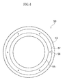
FIGS. 1 and2 . - FIG. 4
- is a front view of a stationary seal ring illustrated in
FIGS. 1 and2 . - FIG. 5
- is a half section of the mechanical seal device according to other embodiments of the present invention.
- A
mechanical seal device 1 according to the present embodiment is a seal device mounted on apparatuses such as stirring machines for general industrial use, blowers, compressors and the like. Particularly, it is used for purposes of manufacturing food products, medical products and chemical substances. - The
mechanical seal device 1 has an inside type structure, in which the sealed fluid is arranged outside in a radial direction with respect to a sealing surface. The sealed fluid at a machine inside B is sealed by theseal device 1 arranged at a clearance formed between arotary shaft 100 and astuffing box 80. Further, inFIGS. 1 and2 , the left side in the axial direction is a machine outside A and the right side in the axial direction is the machine inside B. - A
shaft hole 82 is formed through thestuffing box 80, and therotary shaft 100 rotatably supported by bearings which is not expressed with a figure, extends through thisshaft hole 82. At the inner side of theshaft hole 82 in the radial direction, therotary seal ring 60 is arranged. Therotary seal ring 60 is fixed to therotary shaft 100 while it is positioned by aspacer 75 in the axial direction. Thespacer 75 is arranged between a radial direction steppedportion 102 of therotary shaft 100 and therotary seal ring 60, and therotary seal ring 60 is positioned in the axial direction. Thespacer 75 is composed of materials having excellent strength, such as SUS, engineering plastics and the like. - A
flinger 70 and asleeve 76 are arranged in the axial direction at the machine inside B of therotary seal ring 60. Thesleeve 76 fixes therotary seal ring 60 in the axial direction using theflinger 70. - The
flinger 70 is arranged between thesleeve 76 and therotary seal ring 60 to prevent the solid components in the sealed fluid from entering into between theshaft hole 82 of thestuffing box 80 and the outer circumference surface of therotary seal ring 60 from the machine inside B. Specifically, at the outer circumference of theflinger 70, acylindrical portion 71 extending in the axial direction toward the machine outside A is formed. Thecylindrical portion 71 covers a protrudingportion 86 protruding from thestuffing box 80 in the axial direction toward the machine inside B. Further, theflinger 70 guides the sealed fluid and solid components included therein outwardly in the radial direction by a centrifugal force caused by the rotation together with therotary shaft 100. Therefore, it enables to prevent the solid components in the sealed fluid from entering into between theshaft hole 82 of thestuffing box 80 and the outer circumference surface of therotary seal ring 60. - The inner circumferential surface of the
flinger 70 toward therotary seal ring 60 is formed into a tapered shape, and an O-ring 128 is arranged thereon. The O-ring 128 prevents the sealed fluid from leaking from between therotary seal ring 60 and therotary shaft 100. - The
rotary seal ring 60 has a sealingsurface 62, toward the machine outside A, opposing to a sealingsurface 55 of thestationary seal ring 50. As illustrated inFIG. 3 , on the sealingsurface 62, a dynamicpressure generating grooves 64 are formed. The dynamicpressure generating groove 64 comprises afirst groove 64A for a forward rotation R1 and asecond groove 64B for a reverse rotation R2. Thefirst groove 64A and thesecond groove 64B are symmetrically arranged in the radial direction, and a plurality of pairs of thefirst groove 64A and thesecond groove 64B are formed in a circumferential direction at equal intervals. The dynamicpressure generating groove 64 generates the dynamic pressure by the rotation of therotary seal ring 60 together with therotary shaft 100. - As illustrated in
FIG. 1 , aseal housing 10, anadapter 20, aseal case 30, a bellows 40, astationary seal ring 50 and the like are arranged in the axial direction at the machine outside A of therotary seal ring 60. Theseal housing 10 is attached to thestaffing box 80. Specifically, by passing bolts (not expressed with a figure) embedded at theouter surface 84 of thestaffing box 80 through grooves for attaching a seal housing 10 (not expressed with a figure) and then fastening by nuts (not expressed with a figure), theseal housing 10 is attached on thestaffing box 80. Between theseal housing 10 and thestaffing box 80, the O-ring 120 is arranged in order to prevent the sealed fluid from leaking from between theseal housing 10 and thestaffing box 80. - At the inner
circumferential surface 12 of theseal housing 10, a mountinggroove 16 is formed at the side of theend surface 14 toward the machine inside B in the axial direction and theadapter 20 and theseal case 30 are attached thereon. Theadapter 20 and theseal case 30 are placed in the mountinggroove 16, with the result that it enables to downsize themechanical seal device 1 in the axial direction and in the radial direction. - The
adapter 20 attached to theseal housing 10 has a protrudingportion 22 extending in the axial direction toward the machine inside B and it is mounted on theseal case 30 at the outer side in the radial direction than the protrudingportion 22. Theadapter 20 and theseal case 30 are fixed by afastening member 130. A space between the tip of the protrudingportion 22 and a stepped portion at the inner circumferential surface of theseal case 30 serves as a receiving part that receives an O-ring 122 (seal member). Further, theadapter 20 and theseal case 30 may be integrally formed. Theadapter 20 is defined as a part of theseal case 30 in the present embodiment, even if they are two different parts. - At a stepped outer
diameter end portion 32 of theseal case 30 in the axial direction toward the machine inside B, one end of thebellows 40 is attached. The other end of thebellows 40 is attached to an outer diameter end portion 51 of thestationary seal ring 50. The bellows 40 is arranged at the inner side of theshaft hole 82 of thestaffing box 80, and the sealed fluid is arranged at the outer circumferential side of thebellows 40. The bellows 40 is extendable in the axial direction and also deformable in the radial direction. Therefore, thestationary seal ring 50 attached to thebellows 40 can absorb vibrations of the device, with the result that themechanical seal device 1 can exhibit preferable sealing performance. Further, thebellows 40 is used as seal elements. Therefore, compared with the case using the O-ring and the like, it enables to downsize themechanical seal device 1 in the axial direction and in the radial direction. - The
cylindrical portion 52 is formed on the inner circumferential side of thestationary seal ring 50 to extend in the axial direction toward the machine outside A in the inner circumferential side of thebellows 40. Between the outer circumferential surface of thecylindrical portion 52 and the inner circumferential stepped portion of theseal case 30, the O-ring 122 is arranged. Further, the static pressure fluid chamber C is formed to be surrounded by the O-ring 122, theseal case 30, thebellows 40, and thestationary seal ring 50. The O-ring 122 seals the static pressure fluid chamber C from the atmosphere side space corresponding to the machine outside A. - In the static pressure fluid chamber C, the purge gas as the static pressure fluid (for example, such as nitrogen gas) is supplied from the static pressure
fluid supplying hole 34. The static pressure fluid supplied from the static pressurefluid supplying hole 34 can be appropriately selected according to the use purpose of themechanical seal device 1. For example, the static pressure fluid may be liquids such as water. - The O-
ring 122 seals between the outer circumferential surface of thecylindrical portion 52 of thestationary seal ring 50 and theseal case 30, and further holds thestationary seal ring 50 movably in the axial direction. When thestationary seal ring 50 moves in the axial direction, sliding resistance of one O-ring 122 only acts. Therefore, it enables to smoothly move thestationary seal ring 50 in the axial direction. - Further, the O-
ring 122 is arranged at the inner circumferential surface side of thebellows 40 and it is isolated from the sealed fluid. With this, regardless of the fluid to be sealed, materials of the O-ring 122 can be selected. Further, risks of deterioration due to the contacts of the O-ring 122 with the sealed fluid are eliminated. As a result, in the present invention, it enables to exhibit a preferable sealing performance by smoothly moving thestationary seal ring 50 in the axial direction. - At the atmosphere side of the
cylindrical portion 52 rather than to the O-ring 122, aguide groove 53 and aspring seat 54 are formed. A fixingpin 24 embedded in theadapter 20 is inserted in theguide groove 53, and the fixingpin 24 and theguide groove 53 are relatively movable in the axial direction and are engaged in the circumferential direction. With this, thestationary seal ring 50 is arranged so that it is movable in the axial direction and is unrotatable in the circumferential direction (in a rotation direction of a rotating shaft 100), with respect to theseal cover 30. - A plurality of
spring seats 54 are provided in the circumferential direction to hold a plurality ofcoil springs 140 between the spring seats and opposing surfaces of theadapter 20. The coil springs 140 applies the compressive force pressing thestationary seal ring 50 toward therotary seal ring 60. - In the present embodiment, the fixing pins 24 and the coil springs 140 are arranged at the atmosphere side rather than the O-
ring 122. At the atmosphere side rather than the O-ring 122, the fixing pins 24 and the coil springs 140 do not contact with the sealed fluid and the static pressure fluid, with the result that choices of materials of the above members increase and further risks of deterioration of these members are eliminated. As a result, thestationary seal ring 50 is smoothly moved in the axial direction and thereby enables to exhibit a preferable sealing performance. Further, the structure of the above O-ring 122 and thecoil spring 140 can be replaced with the bellows. - On the
seal case 30, the static pressurefluid supplying hole 34 is formed. The static pressurefluid supplying hole 34 communicates from an outer circumferential end surface of theseal case 30 to the static pressure fluid chamber C in the inner circumferential side of thebellows 40. At the outer circumferential end surface of theseal case 30, the O-rings fluid supplying hole 34 to seal between theseal case 30 and theseal cover 10. At the outside of theseal cover 10, a purge gas supply device (which is not expressed with a figure) is connected. Further, the purge gas supplied from the purge gas supply device is delivered to the static pressure fluid chamber C through agas flow passage 18 of theseal cover 10 and the static pressurefluid supplying hole 34 of theseal case 30. - On the
stationary seal ring 50, communication holes 56 extending from the static pressure fluid chamber C toward the machine inside B are formed in the axial direction. The purge gas guided by the static pressure fluid chamber C passes through the communication holes 56 of thestationary seal ring 50 to be guided toward theseal surface 55. As illustrated inFIG. 4 ,annular grooves 57 continuing to the communication holes 56 are formed on theseal surface 55 of thestationary seal ring 50, and the purge gas guided by the static pressure fluid chamber C passes through the communication holes 56 of thestationary seal ring 50 to be guided by theannular groove 57 at the side of theseal surface 55. Further, a plurality of communication holes 56 are formed along the circumferential direction of theannular grooves 57. Theannular grooves 57 continuing to the communication holes 56 guide the static pressure fluid over the relative sliding surfaces between thestationary seal ring 50 and therotary seal ring 60, with the result that it enables to preferably apply the static pressure on the relative sliding surfaces. Further, on theseal surface 62 of therotary seal ring 60 opposing to theseal surface 55 of thestationary seal ring 50, the dynamicpressure generating grooves 64 are formed. With the dynamicpressure generating grooves 64, the static pressure generates over the relative sliding surfaces. - The purge gas is supplied with a pressure higher than the sealed fluid, and the purge gas guided in the
annular grooves 57 generates the static pressure so that the relative sliding surfaces between theseal surface 55 and theseal surface 62 are prevented from contacting to each other. Further, the purge gas guided in the relative sliding surfaces may be leaked toward the machine inside B and/or the machine outside A. The purge gas leaking toward the machine inside B is discharged from the outer circumferential side of theflinger 70, with the result that it prevents the sealed fluid from entering into theshaft hole 82 of thestaffing box 80 from the machine inside B. With this, the risks that solid components in the sealed fluid stick to the relative sliding surfaces between theseal surface 55 and theseal surface 62 and to the outer circumference of thebellows 40 are eliminated and thereby enables to exhibit preferable sealing performance. - Further, in the present embodiment, the
stationary seal ring 50 and therotary seal ring 60 are composed of materials such as silicon carbide (SiC), carbon, hard metal alloy and the like. Further, examples of materials of the O-rings 120 to 128 include fluororubber, nitrile rubber, EPDM, perfluoroelastomer and the like. - As illustrated in
FIG. 2 , for themechanical seal device 1 of the present embodiment, an inner diameter "dob" of theannular groove 57 of thestationary seal ring 50 is substantially equal to a contact diameter "do" (balance diameter) where the O-ring 122 contacts on thecylindrical portion 52. Further, an outer diameter "dbb" of theannular groove 57 of thestationary seal ring 50 is substantially equal to the pressure acting diameter "db" (average diameter of outer circumferential diameter and inner circumferential diameter of the bellows) of thebellows 40. With the above inner diameter "dob" and the outer diameter "dbb" of theannular groove 57, it enables to freely adjust the compressive force acting on thestationary seal ring 50 as explained below. - For example, the inner diameter "dob" and the outer diameter "dbb" of the
annular groove 57 are formed so as to satisfy the following relation.
(Inner diameter of the annular groove 57) "dob" = "do" (Contact diameter where the O-ring 122 contacts on the cylindrical portion 52)
(Outer diameter of the annular groove 57) "dbb" = "db" (Pressure acting diameter of the bellows 40) - In this case, it is only necessary to satisfy the relation among a dynamic pressure Fd generated by the rotation of the
rotary seal ring 60, a pressing force Fp1 generated by the sealed fluid pressure P1 acting from the outer circumferential side of thebellows 40, a resilient energization force Fs of the spring and the resilient energization force Fb of the bellows as indicated in the followingformula 1, as long as the relation "gas purge pressure P2>sealed fluid pressure P1" is maintained. With this, it enables to simplify the design of themechanical seal device 1.
- For example, in order to increase the compressive force of the
stationary seal ring 50 toward therotary seal ring 60, it is only necessary to make a width (span) of the inner/outer diameter of theannular groove 57 smaller than the case of "dob = do, dbb = db" while maintaining the relation of "Ftc<Fd". - Further, in order to reduce the compressing force toward the
rotary seal ring 60 of thestationary seal ring 50, it is only necessary to make a width of the inner/outer diameter of theannular groove 57 larger than the case "dob = do, dbb = db" while maintaining the relation of "Ftc<Fd". - For the
mechanical seal device 1 having the above structure, thebellows 40 exhibits sealing performance and also applies the compressive force to thestationary seal ring 50. With this, for themechanical seal device 1 of the present embodiment, it enables to substantially reduce the structure such as O-rings and springs. Further, the sliding resistance caused when thestationary seal ring 50 moves in the axial direction is substantially reduced, with the result that it enables preferably to exhibit sealing performance by smoothly moving thestationary seal ring 50 in the axial direction. Further, themechanical seal device 1 has a simple structure, and it is downsized in the axial direction and in the radial direction. - Further, members such as O-
ring 122 andcoil spring 140 arranged at the inner circumference of thebellows 40 do not contact with the sealed fluid. Therefore, even when the fluid including corrosive fluid and solid components is sealed, such members are not deteriorated, with the result that it enables preferably to exhibit sealing performance. Further, it is configured so that the solid components of the sealed fluid do not infiltrate to the outer circumference of thebellows 40, with the result that the solid components of the sealed fluid do not adhere to thebellows 40. The bellows 40 enables preferably to apply the compressive force to thestationary seal ring 50 and thereby themechanical seal device 1 enables preferably to exhibit sealing performance. - As illustrated in
FIG. 5 , a mechanical seal device 1 a according to the present embodiment is an alternative of themechanical seal device 1 of the first embodiment illustrated inFIGS. 1 to 4 , and has the same structure and the same function effects with the first embodiment except for the followings. For the structure common to the first embodiment, similar marks are used in the figure and the explanations for the overlapped parts are omitted. - In this embodiment, inside of the static pressure fluid chamber C, a plurality of
coil springs 140a serving as resilient members are intermittently arranged in a circumferential direction. In order to achieve the above structure, in this embodiment, a cylindrical protrudingportion 26 extending toward therotary seal ring 60 is integrally formed on a radially inner end of theadapter 20. At an outer circumference of tip end of the cylindrical protrudingportion 26, acylindrical portion 52a of thestatic seal ring 50 is movably mounted in the axial direction. - At the inner circumference of the
cylindrical portion 52a, O-ring grooves are formed and O-rings 122a (seal member) are mounted thereon. Further, the O-rings 122a are elastically deformed between the inner circumferential surface of thecylindrical portion 52a of thestatic seal ring 50 and the outer circumferential surface of the cylindrical protrudingportion 26 of theadapter 20 to seal the static fluid chamber C from the atmosphere side space, corresponding to the machine outside A. - Tips of the plurality of
coil springs 140a intermittently arranged in the circumferential direction contact with a back-siderear end 58 of thecylindrical portion 52a (the end opposite to the rotary seal ring 60). The rear ends of eachcoil spring 140a are respectively placed in the spring seats 26, having cylindrical holes, which are intermittently formed along the circumferential direction and radially outward of the cylindrical protrudingportion 26. Eachcoil spring 140a generates a spring force so as to press thestatic seal ring 50 toward therotary seal ring 60. Further, among the spring seats 26 intermittently arranged in the circumferential direction, rotation stop pins preventing thestatic seal ring 50 from rotating relatively with theadapter 20 may be arranged. - Further, in order to ensure the sealing performance between the
adapter 20 and theseal case 30, the O-ring grooves are formed at the outer circumference of an outer circumferentialside protruding portion 22a of theadapter 20 and O-rings 122b are mounted thereon. The O-ring 122b is a seal member to seal the inside of the static fluid chamber C from the atmosphere side space, together with the O-ring 122a. However, the O-ring 122b is not necessary when theadapter 20 is integrally formed with theseal case 30. - In the present embodiment, the shape and pattern of the dynamic
pressure generating groove 64a formed on the seal surface of therotary seal ring 60 may be different from or the same with those of the dynamicpressure generating groove 64 of the first embodiment. Further, in the present embodiment, although theannular grooves 57 as illustrated inFIG. 4 is preferably formed on theseal surface 55 of thestatic seal ring 50, it does not necessarily have to be formed. - In the present embodiment, the
coil spring 140a serving as a resilient member is arranged inside of the static fluid chamber C. Therefore, the pressure of the static pressure fluid in the static pressure fluid chamber C acts on the back-siderear end 58 of thestationary seal ring 50. With this, it enables to increase the force pressing thestationary seal ring 50 to therotary seal ring 60, with the static pressure fluid. The above structure of the present embodiment is especially effective in order to increase the force pressing thestationary seal ring 50 to therotary seal ring 60. - Further, the above embodiments are described so as to facilitate understanding of the present invention, and the present invention is not limited to them only. Each element disclosed in the present embodiments include all design changes and equivalents belonging to the technical scope of the present invention, and further arbitrary suitable modifications can be made.
- The present invention can be used, for example, for pumps for general industrial use and the like. In addition to that, in any apparatuses having a rotary shaft, the present invention can be used as a shaft seal device of the rotary shaft.
-
- 10
- seal housing
- 20
- adapter
- 30
- seal case
- 40
- bellows
- 50
- stationary seal ring
- 56
- communication hole
- 60
- rotary seal ring
- 64, 64a
- dynamic pressure generating groove
- 80
- staffing box
- 100
- rotary shaft
- 122, 122a, 122b
- O-ring
- A
- machine outside
- B
- machine inside
- C
- static pressure fluid chamber
- dob
- inner diameter of annular groove
- do
- contact diameter of O-ring
- dbb
- outer diameter of annular groove
- db
- pressure acting diameter of bellows
Claims (8)
- A mechanical seal device for sealing a sealed fluid inside of a machine at a space formed between a device main body and a rotary shaft, comprising:a seal case attached to the device main body,a rotary seal ring attached to the rotary shaft,a stationary seal ring arranged in an axial direction opposing to the rotary seal ring, anda bellows attached extendably in the axial direction between the stationary seal ring and the seal case, whereina static pressure fluid supplying hole, supplying a static pressure fluid to a static pressure fluid chamber arranged at an inner circumferential side of the bellows, is formed on the seal case,a communication hole, guiding the static pressure fluid of the static pressure fluid chamber to sealing surfaces between the stationary seal ring and the rotary seal ring, is formed on the stationary seal ring, andthe sealed fluid is arranged at an outer circumferential side of the bellows.
- The mechanical seal device as set forth in claim 1, further comprising:a seal member arranged between the seal case and the stationary seal ring at the inner circumferential side of the bellows, holding the stationary seal ring movably in the axial direction and sealing the static pressure fluid chamber from an atmosphere side space.
- The mechanical seal device as set forth in claims 1 or 2, annular grooves connecting to the communication hole are formed on the stationary seal ring.
- The mechanical seal device as set forth in claim 3, wherein
an outer diameter of the annular grooves is designed so that it is nearly equal to a pressure acting diameter of the bellows. - The mechanical seal device as set forth in any one of claims 2 to 4, further comprising:a resilient member arranged closer to the atmosphere side than the seal member and pressing the stationary seal ring toward the rotary seal ring.
- The mechanical seal device as set forth in any one of claims 3 to 5, wherein
an inner diameter of the annular grooves is designed so that it is nearly equal to a contact diameter where the seal member contacts the stationary seal ring. - The mechanical seal device as set forth in any one of claims 1 to 4, further comprising:a resilient member arranged inside the static pressure fluid chamber and pressing the stationary seal ring toward the rotary seal ring.
- The mechanical seal device as set forth in any one of claims 1 to 7, wherein
dynamic pressure generating grooves are formed on the sealing surface of the rotary seal ring.
Applications Claiming Priority (2)
| Application Number | Priority Date | Filing Date | Title |
|---|---|---|---|
| JP2013052091 | 2013-03-14 | ||
| PCT/JP2014/056763 WO2014142265A1 (en) | 2013-03-14 | 2014-03-13 | Mechanical seal device |
Publications (3)
| Publication Number | Publication Date |
|---|---|
| EP2891836A1 true EP2891836A1 (en) | 2015-07-08 |
| EP2891836A4 EP2891836A4 (en) | 2016-05-25 |
| EP2891836B1 EP2891836B1 (en) | 2018-11-07 |
Family
ID=51536914
Family Applications (1)
| Application Number | Title | Priority Date | Filing Date |
|---|---|---|---|
| EP14764286.2A Not-in-force EP2891836B1 (en) | 2013-03-14 | 2014-03-13 | Mechanical seal device |
Country Status (5)
| Country | Link |
|---|---|
| US (1) | US9574667B2 (en) |
| EP (1) | EP2891836B1 (en) |
| JP (1) | JP6219367B2 (en) |
| CN (1) | CN104685273B (en) |
| WO (1) | WO2014142265A1 (en) |
Cited By (1)
| Publication number | Priority date | Publication date | Assignee | Title |
|---|---|---|---|---|
| WO2019132666A1 (en) * | 2017-12-28 | 2019-07-04 | Tocircle Industries As | Sealing arrangement |
Families Citing this family (50)
| Publication number | Priority date | Publication date | Assignee | Title |
|---|---|---|---|---|
| US8436758B2 (en) * | 2010-03-22 | 2013-05-07 | Decawave Ltd. | Adaptive ternary A/D converter for use in an ultra-wideband communication system |
| EP2886914A4 (en) * | 2012-08-22 | 2016-07-27 | Eagle Ind Co Ltd | Double mechanical seal device |
| DE102013227208A1 (en) * | 2013-12-30 | 2015-07-02 | Siemens Aktiengesellschaft | Sealing system for a steam turbine and steam turbine |
| US10274008B2 (en) * | 2015-06-19 | 2019-04-30 | Steering Solutions Ip Holding Corporation | Axial load bearing assembly |
| DE102015212641A1 (en) * | 2015-07-07 | 2017-01-12 | Gapi Technische Produkte Gmbh | Rotary feedthrough for a vehicle |
| DE102016200821B3 (en) * | 2016-01-21 | 2017-05-11 | Eagleburgmann Germany Gmbh & Co. Kg | Mechanical seal assembly with back sealing |
| DE102016200818B4 (en) * | 2016-01-21 | 2020-09-10 | Eagleburgmann Germany Gmbh & Co. Kg | Mechanical seal arrangement with reduced leakage |
| EP3499098B1 (en) | 2016-08-15 | 2024-04-24 | Eagle Industry Co., Ltd. | Sliding component |
| CN106122484B (en) * | 2016-08-18 | 2017-12-05 | 浙江工业大学 | Built-in sealing medium throttling regulation and control device for dynamic and static pressure type dry gas seal |
| USRE50849E1 (en) | 2016-11-16 | 2026-03-31 | Eagle Industry Co., Ltd. | Sliding component |
| CN107504189B (en) * | 2017-08-28 | 2018-11-13 | 浙江工业大学 | A kind of liquid machine sealing device suitable for transformation environment |
| DE102017219190B4 (en) | 2017-10-26 | 2022-12-29 | Eagleburgmann Germany Gmbh & Co. Kg | Gas-lubricated mechanical seal with improved protection against contamination |
| EP3739242A4 (en) * | 2018-01-12 | 2021-10-13 | Eagle Industry Co., Ltd. | SLIDING ELEMENT |
| JP7139077B2 (en) | 2018-02-01 | 2022-09-20 | イーグル工業株式会社 | sliding parts |
| EP3816490B1 (en) | 2018-05-17 | 2024-11-06 | Eagle Industry Co., Ltd. | Seal ring |
| WO2019221226A1 (en) * | 2018-05-17 | 2019-11-21 | イーグル工業株式会社 | Seal ring |
| JP7214722B2 (en) | 2018-05-17 | 2023-01-30 | イーグル工業株式会社 | Seal ring |
| US11644100B2 (en) | 2018-05-17 | 2023-05-09 | Eagle Industry Co., Ltd. | Seal ring |
| EP3862600B1 (en) | 2018-10-01 | 2025-05-21 | Eagle Industry Co., Ltd. | Sliding member |
| CN112789434B (en) | 2018-10-24 | 2023-09-29 | 伊格尔工业股份有限公司 | sliding parts |
| JP7074648B2 (en) | 2018-11-16 | 2022-05-24 | イーグル工業株式会社 | mechanical seal |
| EP4253779B1 (en) | 2019-02-04 | 2024-12-18 | Eagle Industry Co., Ltd. | Sliding component and method for manufacturing sliding component |
| KR102610647B1 (en) | 2019-02-04 | 2023-12-07 | 이구루코교 가부시기가이샤 | sliding parts |
| KR102647265B1 (en) | 2019-02-04 | 2024-03-14 | 이구루코교 가부시기가이샤 | sliding parts |
| EP3922874A4 (en) | 2019-02-04 | 2022-11-09 | Eagle Industry Co., Ltd. | SLIDING ELEMENT |
| CN113348308B (en) | 2019-02-04 | 2023-05-05 | 伊格尔工业股份有限公司 | Sliding member |
| WO2020162351A1 (en) | 2019-02-04 | 2020-08-13 | イーグル工業株式会社 | Sliding component |
| CN117432709A (en) | 2019-02-14 | 2024-01-23 | 伊格尔工业股份有限公司 | sliding parts |
| JP7374573B2 (en) * | 2019-02-21 | 2023-11-07 | イーグル工業株式会社 | sliding parts |
| JP7419346B2 (en) | 2019-03-22 | 2024-01-22 | イーグル工業株式会社 | sliding parts |
| CN115298462B (en) | 2020-03-31 | 2025-04-11 | 伊格尔工业股份有限公司 | Sliding member |
| KR102798715B1 (en) | 2020-05-11 | 2025-04-23 | 이구루코교 가부시기가이샤 | Sliding parts |
| WO2021253449A1 (en) * | 2020-06-19 | 2021-12-23 | 南京千里行测控技术有限公司 | Environmentally friendly sealing apparatus for body of centrifugal blower |
| WO2022009766A1 (en) | 2020-07-06 | 2022-01-13 | イーグル工業株式会社 | Sliding component |
| WO2022009771A1 (en) | 2020-07-06 | 2022-01-13 | イーグル工業株式会社 | Sliding component |
| WO2022009770A1 (en) | 2020-07-06 | 2022-01-13 | イーグル工業株式会社 | Sliding component |
| KR20230022986A (en) | 2020-07-06 | 2023-02-16 | 이구루코교 가부시기가이샤 | sliding parts |
| KR20230027187A (en) | 2020-07-06 | 2023-02-27 | 이구루코교 가부시기가이샤 | sliding parts |
| EP4177485A4 (en) | 2020-07-06 | 2024-07-24 | Eagle Industry Co., Ltd. | SLIDING COMPONENT |
| CN112855937B (en) * | 2021-02-08 | 2022-11-18 | 山东精砼工程机械股份有限公司 | Built-in pressure rotary sealing device and control method |
| EP4306826A4 (en) | 2021-03-12 | 2025-03-26 | Eagle Industry Co., Ltd. | SLIDING ELEMENT |
| US11608751B2 (en) | 2021-03-19 | 2023-03-21 | Raytheon Technologies Corporation | Self-guiding carbon seal system |
| EP4394213A4 (en) | 2021-08-25 | 2025-08-27 | Eagle Ind Co Ltd | PAIR OF SLIDING COMPONENTS |
| US12404936B2 (en) | 2021-09-28 | 2025-09-02 | Eagle Indusry Co., Ltd. | Sliding component |
| CN119301388A (en) * | 2022-06-07 | 2025-01-10 | 伊格尔工业股份有限公司 | Sliding parts |
| CN116045001B (en) * | 2022-12-21 | 2025-07-15 | 湖南宏工智能科技有限公司 | Mechanical seal with adjustable pressure |
| KR102829619B1 (en) * | 2022-12-23 | 2025-07-07 | 한국항공우주연구원 | Centrifugal pump with pressure drop seal |
| JP7787359B2 (en) * | 2023-02-13 | 2025-12-16 | イーグル工業株式会社 | Mechanical seal |
| US12580440B2 (en) * | 2023-06-08 | 2026-03-17 | Enedym Inc. | Motor housing design for rotor-axial-displacement-independent and mounting-orientation-independent ingress protection |
| CN117989236B (en) * | 2023-12-14 | 2024-09-17 | 中国船舶集团有限公司第七一九研究所 | Electric heating dehumidification static pressure air bearing |
Family Cites Families (20)
| Publication number | Priority date | Publication date | Assignee | Title |
|---|---|---|---|---|
| CH384303A (en) | 1959-04-02 | 1964-11-15 | Ass Elect Ind | Gas-tight seal |
| FR1276470A (en) | 1960-12-21 | 1961-11-17 | Cie Constr Gros Mat Electromec | Sealing device for rotating machine |
| GB1309865A (en) | 1971-01-22 | 1973-03-14 | English Electric Co Ltd | Combined static and fluid selas |
| JPS5543328Y2 (en) * | 1974-08-05 | 1980-10-11 | ||
| US4335888A (en) * | 1978-03-20 | 1982-06-22 | Nippon Pillar Packing Co. Ltd. | Mechanical seal |
| JPS6215564Y2 (en) * | 1981-05-27 | 1987-04-20 | ||
| JPS5983255U (en) * | 1982-11-27 | 1984-06-05 | 日本ピラ−工業株式会社 | Fluororesin bellows type mechanical seal |
| FI71824C (en) * | 1985-04-12 | 1987-02-09 | Safematic Ltd Oy | MEKANISK TAETNING. |
| CH668813A5 (en) | 1986-02-05 | 1989-01-31 | Escher Wyss Ag | GAS LOCKED AXIAL SHAFT SEAL. |
| JPH01187910A (en) * | 1988-01-22 | 1989-07-27 | Asahi Kiko Kk | Automatic tape winding machine for coil |
| US4973065A (en) * | 1989-10-20 | 1990-11-27 | A. W. Chesterton Company | Seal assembly |
| DE4241948A1 (en) * | 1992-12-12 | 1994-06-16 | Hoechst Ag | Graft polymers, their preparation and use as pour point depressants and flow improvers for crude oils, residual oils and middle distillates |
| JP3711308B2 (en) | 1997-07-04 | 2005-11-02 | 株式会社シマノ | Spinning reel slider mounting structure |
| BR9714210A (en) | 1997-11-21 | 2000-03-28 | Nippon Pillar Packing | Static pressure non-contact gas sealing |
| DE19846153C1 (en) * | 1998-10-07 | 2000-04-20 | Freudenberg Carl Fa | Mechanical seal |
| JP4820471B2 (en) | 2004-11-09 | 2011-11-24 | イーグル工業株式会社 | Mechanical seal device |
| EP1895209B1 (en) * | 2005-06-20 | 2012-12-26 | Eagle Industry Co., Ltd. | Mechanical seal |
| WO2010123025A1 (en) * | 2009-04-23 | 2010-10-28 | イーグル工業株式会社 | Mechanical seal device |
| EP2886914A4 (en) * | 2012-08-22 | 2016-07-27 | Eagle Ind Co Ltd | Double mechanical seal device |
| US20150240950A1 (en) * | 2012-10-19 | 2015-08-27 | EagleBurgmann Japan Co., Ltd. | Bellows Seal |
-
2014
- 2014-03-13 JP JP2015505569A patent/JP6219367B2/en active Active
- 2014-03-13 EP EP14764286.2A patent/EP2891836B1/en not_active Not-in-force
- 2014-03-13 US US14/432,396 patent/US9574667B2/en not_active Expired - Fee Related
- 2014-03-13 CN CN201480002582.5A patent/CN104685273B/en not_active Expired - Fee Related
- 2014-03-13 WO PCT/JP2014/056763 patent/WO2014142265A1/en not_active Ceased
Cited By (1)
| Publication number | Priority date | Publication date | Assignee | Title |
|---|---|---|---|---|
| WO2019132666A1 (en) * | 2017-12-28 | 2019-07-04 | Tocircle Industries As | Sealing arrangement |
Also Published As
| Publication number | Publication date |
|---|---|
| US9574667B2 (en) | 2017-02-21 |
| CN104685273B (en) | 2016-07-06 |
| WO2014142265A1 (en) | 2014-09-18 |
| EP2891836B1 (en) | 2018-11-07 |
| JP6219367B2 (en) | 2017-10-25 |
| US20160003361A1 (en) | 2016-01-07 |
| CN104685273A (en) | 2015-06-03 |
| EP2891836A4 (en) | 2016-05-25 |
| JPWO2014142265A1 (en) | 2017-02-16 |
Similar Documents
| Publication | Publication Date | Title |
|---|---|---|
| EP2891836B1 (en) | Mechanical seal device | |
| CN102369375B (en) | Mechanical seal device | |
| EP2385278A1 (en) | Low breakout friction energized gasket | |
| JP2011017438A (en) | Double direction seal with locking | |
| JP5130568B2 (en) | Mechanical seal device | |
| JP6140179B2 (en) | Mechanical seal device | |
| JP2008506084A (en) | Composite rotary seal assembly | |
| US11821522B2 (en) | Mechanical seal arrangement suitable for pressure reversal | |
| US9841108B2 (en) | Mechanical seal | |
| AU2015270310B2 (en) | High-pressure rotary seal-plug assembly with expandable continuous ring | |
| US11221074B2 (en) | Mechanical seal | |
| US10352449B2 (en) | Mechanical seal | |
| EP3805616A1 (en) | Seal ring and sealing structure | |
| US11933313B2 (en) | Seal arrangement for pump | |
| JP7745759B2 (en) | Conical seal assembly for rotary equipment and rotary equipment including the seal assembly - Patents.com | |
| CN104662315B (en) | Sealing ring and sealing cartridge with such a sealing ring | |
| JP2018146079A (en) | Mechanical seal for slurry fluid | |
| US10648570B2 (en) | Gas seal | |
| EP2375073A1 (en) | Sealing for the control chamber of a variable displacement lubricant pump | |
| JP6128600B2 (en) | Mechanical seal device |
Legal Events
| Date | Code | Title | Description |
|---|---|---|---|
| PUAI | Public reference made under article 153(3) epc to a published international application that has entered the european phase |
Free format text: ORIGINAL CODE: 0009012 |
|
| 17P | Request for examination filed |
Effective date: 20150331 |
|
| AK | Designated contracting states |
Kind code of ref document: A1 Designated state(s): AL AT BE BG CH CY CZ DE DK EE ES FI FR GB GR HR HU IE IS IT LI LT LU LV MC MK MT NL NO PL PT RO RS SE SI SK SM TR |
|
| AX | Request for extension of the european patent |
Extension state: BA ME |
|
| RA4 | Supplementary search report drawn up and despatched (corrected) |
Effective date: 20160426 |
|
| RIC1 | Information provided on ipc code assigned before grant |
Ipc: F16J 15/36 20060101ALI20160420BHEP Ipc: F16J 15/34 20060101AFI20160420BHEP Ipc: F16J 15/52 20060101ALI20160420BHEP Ipc: F16J 3/04 20060101ALI20160420BHEP |
|
| DAX | Request for extension of the european patent (deleted) | ||
| STAA | Information on the status of an ep patent application or granted ep patent |
Free format text: STATUS: EXAMINATION IS IN PROGRESS |
|
| 17Q | First examination report despatched |
Effective date: 20170314 |
|
| GRAP | Despatch of communication of intention to grant a patent |
Free format text: ORIGINAL CODE: EPIDOSNIGR1 |
|
| STAA | Information on the status of an ep patent application or granted ep patent |
Free format text: STATUS: GRANT OF PATENT IS INTENDED |
|
| INTG | Intention to grant announced |
Effective date: 20180524 |
|
| GRAS | Grant fee paid |
Free format text: ORIGINAL CODE: EPIDOSNIGR3 |
|
| GRAA | (expected) grant |
Free format text: ORIGINAL CODE: 0009210 |
|
| STAA | Information on the status of an ep patent application or granted ep patent |
Free format text: STATUS: THE PATENT HAS BEEN GRANTED |
|
| RAP1 | Party data changed (applicant data changed or rights of an application transferred) |
Owner name: EAGLE INDUSTRY CO., LTD. Owner name: EAGLE BURGMANN JAPAN CO., LTD. |
|
| RAP1 | Party data changed (applicant data changed or rights of an application transferred) |
Owner name: EAGLE BURGMANN JAPAN CO., LTD. Owner name: EAGLE INDUSTRY CO., LTD. |
|
| AK | Designated contracting states |
Kind code of ref document: B1 Designated state(s): AL AT BE BG CH CY CZ DE DK EE ES FI FR GB GR HR HU IE IS IT LI LT LU LV MC MK MT NL NO PL PT RO RS SE SI SK SM TR |
|
| REG | Reference to a national code |
Ref country code: GB Ref legal event code: FG4D |
|
| REG | Reference to a national code |
Ref country code: CH Ref legal event code: EP Ref country code: AT Ref legal event code: REF Ref document number: 1062436 Country of ref document: AT Kind code of ref document: T Effective date: 20181115 |
|
| REG | Reference to a national code |
Ref country code: IE Ref legal event code: FG4D |
|
| REG | Reference to a national code |
Ref country code: DE Ref legal event code: R096 Ref document number: 602014035603 Country of ref document: DE |
|
| REG | Reference to a national code |
Ref country code: NL Ref legal event code: MP Effective date: 20181107 |
|
| REG | Reference to a national code |
Ref country code: LT Ref legal event code: MG4D |
|
| REG | Reference to a national code |
Ref country code: AT Ref legal event code: MK05 Ref document number: 1062436 Country of ref document: AT Kind code of ref document: T Effective date: 20181107 |
|
| PG25 | Lapsed in a contracting state [announced via postgrant information from national office to epo] |
Ref country code: IS Free format text: LAPSE BECAUSE OF FAILURE TO SUBMIT A TRANSLATION OF THE DESCRIPTION OR TO PAY THE FEE WITHIN THE PRESCRIBED TIME-LIMIT Effective date: 20190307 Ref country code: FI Free format text: LAPSE BECAUSE OF FAILURE TO SUBMIT A TRANSLATION OF THE DESCRIPTION OR TO PAY THE FEE WITHIN THE PRESCRIBED TIME-LIMIT Effective date: 20181107 Ref country code: BG Free format text: LAPSE BECAUSE OF FAILURE TO SUBMIT A TRANSLATION OF THE DESCRIPTION OR TO PAY THE FEE WITHIN THE PRESCRIBED TIME-LIMIT Effective date: 20190207 Ref country code: LT Free format text: LAPSE BECAUSE OF FAILURE TO SUBMIT A TRANSLATION OF THE DESCRIPTION OR TO PAY THE FEE WITHIN THE PRESCRIBED TIME-LIMIT Effective date: 20181107 Ref country code: NO Free format text: LAPSE BECAUSE OF FAILURE TO SUBMIT A TRANSLATION OF THE DESCRIPTION OR TO PAY THE FEE WITHIN THE PRESCRIBED TIME-LIMIT Effective date: 20190207 Ref country code: AT Free format text: LAPSE BECAUSE OF FAILURE TO SUBMIT A TRANSLATION OF THE DESCRIPTION OR TO PAY THE FEE WITHIN THE PRESCRIBED TIME-LIMIT Effective date: 20181107 Ref country code: ES Free format text: LAPSE BECAUSE OF FAILURE TO SUBMIT A TRANSLATION OF THE DESCRIPTION OR TO PAY THE FEE WITHIN THE PRESCRIBED TIME-LIMIT Effective date: 20181107 Ref country code: HR Free format text: LAPSE BECAUSE OF FAILURE TO SUBMIT A TRANSLATION OF THE DESCRIPTION OR TO PAY THE FEE WITHIN THE PRESCRIBED TIME-LIMIT Effective date: 20181107 Ref country code: LV Free format text: LAPSE BECAUSE OF FAILURE TO SUBMIT A TRANSLATION OF THE DESCRIPTION OR TO PAY THE FEE WITHIN THE PRESCRIBED TIME-LIMIT Effective date: 20181107 |
|
| PG25 | Lapsed in a contracting state [announced via postgrant information from national office to epo] |
Ref country code: PT Free format text: LAPSE BECAUSE OF FAILURE TO SUBMIT A TRANSLATION OF THE DESCRIPTION OR TO PAY THE FEE WITHIN THE PRESCRIBED TIME-LIMIT Effective date: 20190307 Ref country code: AL Free format text: LAPSE BECAUSE OF FAILURE TO SUBMIT A TRANSLATION OF THE DESCRIPTION OR TO PAY THE FEE WITHIN THE PRESCRIBED TIME-LIMIT Effective date: 20181107 Ref country code: SE Free format text: LAPSE BECAUSE OF FAILURE TO SUBMIT A TRANSLATION OF THE DESCRIPTION OR TO PAY THE FEE WITHIN THE PRESCRIBED TIME-LIMIT Effective date: 20181107 Ref country code: RS Free format text: LAPSE BECAUSE OF FAILURE TO SUBMIT A TRANSLATION OF THE DESCRIPTION OR TO PAY THE FEE WITHIN THE PRESCRIBED TIME-LIMIT Effective date: 20181107 Ref country code: NL Free format text: LAPSE BECAUSE OF FAILURE TO SUBMIT A TRANSLATION OF THE DESCRIPTION OR TO PAY THE FEE WITHIN THE PRESCRIBED TIME-LIMIT Effective date: 20181107 Ref country code: GR Free format text: LAPSE BECAUSE OF FAILURE TO SUBMIT A TRANSLATION OF THE DESCRIPTION OR TO PAY THE FEE WITHIN THE PRESCRIBED TIME-LIMIT Effective date: 20190208 |
|
| PG25 | Lapsed in a contracting state [announced via postgrant information from national office to epo] |
Ref country code: IT Free format text: LAPSE BECAUSE OF FAILURE TO SUBMIT A TRANSLATION OF THE DESCRIPTION OR TO PAY THE FEE WITHIN THE PRESCRIBED TIME-LIMIT Effective date: 20181107 Ref country code: CZ Free format text: LAPSE BECAUSE OF FAILURE TO SUBMIT A TRANSLATION OF THE DESCRIPTION OR TO PAY THE FEE WITHIN THE PRESCRIBED TIME-LIMIT Effective date: 20181107 Ref country code: PL Free format text: LAPSE BECAUSE OF FAILURE TO SUBMIT A TRANSLATION OF THE DESCRIPTION OR TO PAY THE FEE WITHIN THE PRESCRIBED TIME-LIMIT Effective date: 20181107 Ref country code: DK Free format text: LAPSE BECAUSE OF FAILURE TO SUBMIT A TRANSLATION OF THE DESCRIPTION OR TO PAY THE FEE WITHIN THE PRESCRIBED TIME-LIMIT Effective date: 20181107 |
|
| REG | Reference to a national code |
Ref country code: DE Ref legal event code: R097 Ref document number: 602014035603 Country of ref document: DE |
|
| PG25 | Lapsed in a contracting state [announced via postgrant information from national office to epo] |
Ref country code: SM Free format text: LAPSE BECAUSE OF FAILURE TO SUBMIT A TRANSLATION OF THE DESCRIPTION OR TO PAY THE FEE WITHIN THE PRESCRIBED TIME-LIMIT Effective date: 20181107 Ref country code: EE Free format text: LAPSE BECAUSE OF FAILURE TO SUBMIT A TRANSLATION OF THE DESCRIPTION OR TO PAY THE FEE WITHIN THE PRESCRIBED TIME-LIMIT Effective date: 20181107 Ref country code: RO Free format text: LAPSE BECAUSE OF FAILURE TO SUBMIT A TRANSLATION OF THE DESCRIPTION OR TO PAY THE FEE WITHIN THE PRESCRIBED TIME-LIMIT Effective date: 20181107 Ref country code: SK Free format text: LAPSE BECAUSE OF FAILURE TO SUBMIT A TRANSLATION OF THE DESCRIPTION OR TO PAY THE FEE WITHIN THE PRESCRIBED TIME-LIMIT Effective date: 20181107 |
|
| PLBE | No opposition filed within time limit |
Free format text: ORIGINAL CODE: 0009261 |
|
| STAA | Information on the status of an ep patent application or granted ep patent |
Free format text: STATUS: NO OPPOSITION FILED WITHIN TIME LIMIT |
|
| REG | Reference to a national code |
Ref country code: DE Ref legal event code: R119 Ref document number: 602014035603 Country of ref document: DE |
|
| 26N | No opposition filed |
Effective date: 20190808 |
|
| PG25 | Lapsed in a contracting state [announced via postgrant information from national office to epo] |
Ref country code: SI Free format text: LAPSE BECAUSE OF FAILURE TO SUBMIT A TRANSLATION OF THE DESCRIPTION OR TO PAY THE FEE WITHIN THE PRESCRIBED TIME-LIMIT Effective date: 20181107 Ref country code: MC Free format text: LAPSE BECAUSE OF FAILURE TO SUBMIT A TRANSLATION OF THE DESCRIPTION OR TO PAY THE FEE WITHIN THE PRESCRIBED TIME-LIMIT Effective date: 20181107 |
|
| REG | Reference to a national code |
Ref country code: CH Ref legal event code: PL |
|
| GBPC | Gb: european patent ceased through non-payment of renewal fee |
Effective date: 20190313 |
|
| PG25 | Lapsed in a contracting state [announced via postgrant information from national office to epo] |
Ref country code: LU Free format text: LAPSE BECAUSE OF NON-PAYMENT OF DUE FEES Effective date: 20190313 |
|
| REG | Reference to a national code |
Ref country code: BE Ref legal event code: MM Effective date: 20190331 |
|
| PG25 | Lapsed in a contracting state [announced via postgrant information from national office to epo] |
Ref country code: DE Free format text: LAPSE BECAUSE OF NON-PAYMENT OF DUE FEES Effective date: 20191001 Ref country code: CH Free format text: LAPSE BECAUSE OF NON-PAYMENT OF DUE FEES Effective date: 20190331 Ref country code: LI Free format text: LAPSE BECAUSE OF NON-PAYMENT OF DUE FEES Effective date: 20190331 Ref country code: IE Free format text: LAPSE BECAUSE OF NON-PAYMENT OF DUE FEES Effective date: 20190313 Ref country code: GB Free format text: LAPSE BECAUSE OF NON-PAYMENT OF DUE FEES Effective date: 20190313 |
|
| PG25 | Lapsed in a contracting state [announced via postgrant information from national office to epo] |
Ref country code: FR Free format text: LAPSE BECAUSE OF NON-PAYMENT OF DUE FEES Effective date: 20190331 Ref country code: BE Free format text: LAPSE BECAUSE OF NON-PAYMENT OF DUE FEES Effective date: 20190331 |
|
| PG25 | Lapsed in a contracting state [announced via postgrant information from national office to epo] |
Ref country code: TR Free format text: LAPSE BECAUSE OF FAILURE TO SUBMIT A TRANSLATION OF THE DESCRIPTION OR TO PAY THE FEE WITHIN THE PRESCRIBED TIME-LIMIT Effective date: 20181107 |
|
| PG25 | Lapsed in a contracting state [announced via postgrant information from national office to epo] |
Ref country code: MT Free format text: LAPSE BECAUSE OF NON-PAYMENT OF DUE FEES Effective date: 20190313 |
|
| PG25 | Lapsed in a contracting state [announced via postgrant information from national office to epo] |
Ref country code: CY Free format text: LAPSE BECAUSE OF FAILURE TO SUBMIT A TRANSLATION OF THE DESCRIPTION OR TO PAY THE FEE WITHIN THE PRESCRIBED TIME-LIMIT Effective date: 20181107 |
|
| PG25 | Lapsed in a contracting state [announced via postgrant information from national office to epo] |
Ref country code: HU Free format text: LAPSE BECAUSE OF FAILURE TO SUBMIT A TRANSLATION OF THE DESCRIPTION OR TO PAY THE FEE WITHIN THE PRESCRIBED TIME-LIMIT; INVALID AB INITIO Effective date: 20140313 |
|
| PG25 | Lapsed in a contracting state [announced via postgrant information from national office to epo] |
Ref country code: MK Free format text: LAPSE BECAUSE OF FAILURE TO SUBMIT A TRANSLATION OF THE DESCRIPTION OR TO PAY THE FEE WITHIN THE PRESCRIBED TIME-LIMIT Effective date: 20181107 |