EP2891833A1 - Carrier shaft set - Google Patents
Carrier shaft set Download PDFInfo
- Publication number
- EP2891833A1 EP2891833A1 EP14200640.2A EP14200640A EP2891833A1 EP 2891833 A1 EP2891833 A1 EP 2891833A1 EP 14200640 A EP14200640 A EP 14200640A EP 2891833 A1 EP2891833 A1 EP 2891833A1
- Authority
- EP
- European Patent Office
- Prior art keywords
- carrier shaft
- shaft portion
- input
- wedge
- planetary gear
- Prior art date
- Legal status (The legal status is an assumption and is not a legal conclusion. Google has not performed a legal analysis and makes no representation as to the accuracy of the status listed.)
- Granted
Links
Images





Classifications
-
- F—MECHANICAL ENGINEERING; LIGHTING; HEATING; WEAPONS; BLASTING
- F16—ENGINEERING ELEMENTS AND UNITS; GENERAL MEASURES FOR PRODUCING AND MAINTAINING EFFECTIVE FUNCTIONING OF MACHINES OR INSTALLATIONS; THERMAL INSULATION IN GENERAL
- F16H—GEARING
- F16H57/00—General details of gearing
- F16H57/08—General details of gearing of gearings with members having orbital motion
- F16H57/082—Planet carriers
-
- H—ELECTRICITY
- H02—GENERATION; CONVERSION OR DISTRIBUTION OF ELECTRIC POWER
- H02K—DYNAMO-ELECTRIC MACHINES
- H02K7/00—Arrangements for handling mechanical energy structurally associated with dynamo-electric machines, e.g. structural association with mechanical driving motors or auxiliary dynamo-electric machines
- H02K7/003—Couplings; Details of shafts
-
- Y—GENERAL TAGGING OF NEW TECHNOLOGICAL DEVELOPMENTS; GENERAL TAGGING OF CROSS-SECTIONAL TECHNOLOGIES SPANNING OVER SEVERAL SECTIONS OF THE IPC; TECHNICAL SUBJECTS COVERED BY FORMER USPC CROSS-REFERENCE ART COLLECTIONS [XRACs] AND DIGESTS
- Y10—TECHNICAL SUBJECTS COVERED BY FORMER USPC
- Y10T—TECHNICAL SUBJECTS COVERED BY FORMER US CLASSIFICATION
- Y10T29/00—Metal working
- Y10T29/49—Method of mechanical manufacture
- Y10T29/49462—Gear making
- Y10T29/49465—Gear mounting
Definitions
- the subject matter disclosed herein relates to integrated drive generators (IDGs), and more specifically, to an IDG carrier shaft set.
- a drive shaft connectable to an output shaft driven by an aircraft engine is connected to a mechanical differential, with the differential having an output connected to drive the generator.
- a variable speed transmission such as a hydrostatic transmission or log, is associated with the mechanical differential and controlled to modify the output of the differential, as required, whereby the input speed to the generator remains constant even though the speed of the drive shaft may vary.
- a carrier shaft assembly can support a number of loads associated with driving the IDG through a planetary gear system disposed within and about a carrier shaft set that includes a carrier shaft and an input carrier shaft.
- a carrier shaft set is typically designed with symmetrical machining about a principle axis. When the carrier shaft assembly is oriented in operation to rotate about an operational axis that is different than the principle axis, a rotational load imbalance imparts additional forces. Imbalanced bearing loads can lead to premature wear and/or failure. Accordingly, there is a need for a carrier shaft set and assembly that reduce rotational load imbalance in an IDG system.
- a carrier shaft set includes an input carrier shaft portion and a carrier shaft portion.
- the input carrier shaft portion has an input carrier shaft portion axis defined between a planetary gear set end and an input shaft end, where the input shaft end has an outer surface.
- the input carrier shaft portion includes a wedge-shaped member having an edge and an outer edge that defines a taper region relative to the edge of the wedge-shaped member.
- a ratio of a length defined between the input carrier shaft portion axis and the outer edge to the outer surface of the input shaft end is between 1.23 and 1.30.
- the carrier shaft portion has a carrier shaft portion axis defined between a planetary gear set end and a shaft end.
- the carrier shaft portion includes a shaft portion having an outer surface and a wedge-shaped member having an edge and an outer edge that defines a taper region relative to the edge of the wedge-shaped member.
- a ratio of a length defined between the carrier shaft portion axis and the outer edge to the outer surface of the shaft portion is between 1.23 and 1.30.
- a method for assembling a carrier shaft assembly includes providing an input carrier shaft portion having an input carrier shaft portion axis defined between a planetary gear set end and an input shaft end, where the input shaft end has an outer surface.
- the input carrier shaft portion includes a wedge-shaped member having an edge and an outer edge that defines a taper region relative to the edge of the wedge-shaped member.
- a ratio of a length defined between the input carrier shaft portion axis and the outer edge to the outer surface of the input shaft end is between 1.23 and 1.30.
- the method also includes providing a carrier shaft portion having a carrier shaft portion axis defined between a planetary gear set end and a shaft end.
- the carrier shaft portion includes a shaft portion having an outer surface and a wedge-shaped member having an edge and an outer edge that defines a taper region relative to the edge of the wedge-shaped member.
- a ratio of a length defined between the carrier shaft portion axis and the outer edge to the outer surface of the shaft portion is between 1.23 and 1.30.
- the method further includes aligning the input carrier shaft portion axis of the input carrier shaft portion with the carrier shaft portion axis of the carrier shaft portion to form a principle axis of the carrier shaft assembly.
- the carrier shaft assembly 10 for an integrated drive generator (IDG) is illustrated.
- the carrier shaft assembly 10 includes a carrier shaft portion 20, an input carrier shaft portion 30, and a planetary gear set 40 as best viewed in FIG. 2 .
- the carrier shaft portion 20 and the input carrier shaft portion 30 are together referred to as a carrier shaft set 50.
- the carrier shaft portion 20 includes a first geared portion 21 proximate a shaft end 22 and a second geared portion 23 proximate a planetary gear set end 24.
- the carrier shaft portion 20 also includes a first bearing race 25 and a second bearing race 26.
- the first bearing race 25 and the second bearing race 26 are disposed to receive bearings to support a differential including an output ring gear (not depicted) for an IDG.
- the input carrier shaft portion 30 also includes a first bearing race 31 proximate a planetary gear set end 32 and a second bearing race 33 proximate an input shaft end 34.
- the first bearing race 31 and the second bearing race 33 are disposed to receive bearings to support an input ring gear (not depicted) for an IDG.
- the planetary gear set 40 includes a first planet shaft 41 with a first planet gear 42 and a second planet shaft 43 with a second planet gear 44.
- the planetary gear set 40 may be part of a planetary gear system for an IDG that includes an input ring gear and an output ring gear (not depicted).
- the first planet shaft 41 is proximate a bore 27 in a planetary gear set side 28 of the carrier shaft portion 20.
- the second planet shaft 43 is proximate a bore 35 in a planetary gear set side 36 of the input carrier shaft portion 30.
- the carrier shaft assembly 10 has a principle axis A defined as a centerline through the carrier shaft assembly 10.
- An operational axis O of the carrier shaft assembly 10 is offset from the principle axis A when operably installed in an IDG. Misalignment of the operational axis O relative to the principle axis A may result in inducing a force F1 from the first bearing race 25 of the carrier shaft portion 20 and a force F2 from the second bearing race 33 of the input carrier shaft portion 30. Forces F1 and F2 can result in imbalance bearing loads in multiple bearings (not depicted).
- An exemplary embodiment reduces the forces F1 and F2 while supporting gear loads and maintaining products of inertia as close to zero as reasonably possible for the carrier shaft assembly 10.
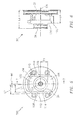
- FIG. 3 is a perspective view of the carrier shaft assembly 10 of FIG. 1 at an input side 100 of the input carrier shaft portion 30.
- the input side 100 of the input carrier shaft portion 30 includes a wedge-shaped member 102 having a wider wedge portion 104 and a narrower wedge portion 106 proximate the second bearing race 33 of the input carrier shaft portion 30.
- FIG. 4 is a perspective view of the carrier shaft assembly 10 of FIG. 1 at a carrier shaft side 200 of the carrier shaft portion 20.
- the carrier shaft side 200 of the carrier shaft portion 20 includes a wedge-shaped member 202 having a wider wedge portion 204 and a narrower wedge portion 206 proximate the first bearing race 25 of the carrier shaft portion 20.
- the wider wedge portion 104 of the input carrier shaft portion 30 is substantially axially aligned with the narrower wedge portion 206 of the carrier shaft portion 20.
- the narrower wedge portion 106 of the input carrier shaft portion 30 is substantially axially aligned with the wider wedge portion 204 of the carrier shaft portion 20.
- FIG. 5 is an end view of the input carrier shaft portion 30 of the carrier shaft assembly 10 of FIG. 1 at the input side 100.
- An input carrier shaft portion axis ICA of the input carrier shaft portion 30 is defined between the planetary gear set end 32 and the input shaft end 34 of FIG. 1 to align with the principle axis A of FIG. 1 .
- an outer surface R1 of the input shaft end 34 is about 0.75 inches (1.905 cm) relative to ICA.
- the wider wedge portion 104 and the narrower wedge portion 106 are defined by edges 108 and 110 of the wedge-shaped member 102 offset at an angle ⁇ 1 of about 2.0 degrees from normal with respect to ICA.
- An outer edge 112 defines a taper region 114 relative to edge 108, and an outer edge 116 defines a taper region 118 relative to edge 110 such that the taper regions 114 and 118 are substantially symmetric about ICA with respect to each other.
- a length L1 defined between ICA and edge 108 is about 0.781 inches (1.984 cm)
- a length L2 defined between ICA and outer edge 112 is about 0.95 inches (2.413 cm).
- a ratio of length L1 to the outer surface R1 is between 1.01 and 1.07.
- a ratio of length L2 to the outer surface R1 is between 1.23 and 1.30.
- FIG. 6 is a side view of the input carrier shaft portion 30 of the carrier shaft assembly 10 of FIG. 1 .
- the input carrier shaft portion 30 has a length L3 of about 1.896 inches (4.816 cm) defined between the planetary gear set end 32 and the input shaft end 34.
- a length L4 of about 1.345 inches (3.416 cm) is defined between the planetary gear set end 32 and a surface 120 of the narrower wedge portion 106.
- a ratio of length L3 to length L4 is between 1.39 and 1.43.
- FIG. 7 is a cross-sectional view of the input carrier shaft portion 30 of the carrier shaft assembly 10 of FIG. 1 taken at section line 7-7 of FIG. 5 .
- FIG. 7 depicts bore 35 is greater detail.
- the bore 35 extends a length L5 of about 1.124 inches (2.855 cm) from the planetary gear set end 32 and has a diameter D1 of about 0.5 inches (1.27 cm).
- a ratio of length L5 to diameter D1 is between 2.2 and 2.3.
- FIG. 8 is a side view of the carrier shaft portion 20 of the carrier shaft assembly 10 of FIG. 1 .
- a carrier shaft portion axis CA of the carrier shaft portion 20 is defined between the planetary gear set end 24 and the shaft end 22 to align with the principle axis A of FIG. 1 .
- the carrier shaft portion 20 has a length L6 of about 6.09 inches (15.469 cm) from the shaft end 22 to the planetary gear set end 24.
- a length L7 of about 1.758 inches (4.465 cm) is defined between a surface 208 of the wider wedge portion 204 and the planetary gear set end 24.
- a ratio of length L6 to length L7 is between 3.44 and 3.49.
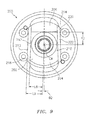
- FIG. 9 is an end view of the carrier shaft portion 20 of the carrier shaft assembly 10 of FIG. 1 at the carrier shaft side 200.
- an outer surface R2 of a shaft portion 210 is about 0.75 inches (1.905 cm) relative to CA.
- the wider wedge portion 204 and the narrower wedge portion 206 are defined by edges 212 and 214 of the wedge-shaped member 202 offset at an angle ⁇ 2 of about 2 degrees from normal with respect to CA.
- An outer edge 216 defines a taper region 218 relative to edge 212, and an outer edge 220 defines a taper region 222 relative to edge 214 such that the taper regions 218 and 222 are substantially symmetric about CA with respect to each other.
- a length L8 defined between CA and edge 212 is about 0.781 inches (1.984 cm), and a length L9 defined between CA and outer edge 216 is about 0.95 inches (2.413 cm).
- a ratio of length L8 to the outer surface R2 is between 1.01 and 1.07.
- a ratio of length L9 to the outer surface R2 is between 1.23 and 1.30.
- FIG. 10 is an end view of the carrier shaft portion 20 of the carrier shaft assembly 10 of FIG. 1 on the planetary gear set side 28.
- Section line 11-11 in FIG. 10 defines a cross-sectional view of the carrier shaft portion 20 as depicted in FIG. 11.
- FIG. 11 depicts bore 27 is greater detail.
- the bore 27 extends a length L10 of about 1.447 inches (3.675 cm) from the planetary gear set end 24 and has a diameter D2 of about 0.375 inches (0.953 cm).
- a ratio of length L10 to diameter D2 is between 3.73 and 4.
- a method for assembling a carrier shaft assembly includes providing an input carrier shaft portion 30 having an input carrier shaft portion axis ICA defined between a planetary gear set end 32 and an input shaft end 34, where the input shaft end 34 has an outer surface R1.
- the input carrier shaft portion 30 includes a wedge-shaped member 102 having an edge 108 and an outer edge 112 that defines a taper region 114 relative to the edge 108 of the wedge-shaped member 102.
- a ratio of a length L2 defined between the input carrier shaft portion axis ICA and the outer edge 112 to the outer surface R1 of the input shaft end 34 is between 1.23 and 1.30.
- the method also includes providing a carrier shaft portion 20 having a carrier shaft portion axis CA defined between a planetary gear set end 24 and a shaft end 22.
- the carrier shaft portion 20 includes a shaft portion 210 having an outer surface R2 and a wedge-shaped member 202 having an edge 212 and an outer edge 216 that defines a taper region 218 relative to the edge 212 of the wedge-shaped member 202.
- a ratio of a length L9 defined between the carrier shaft portion axis CA and the outer edge 216 of the wedge-shaped member 202 to the outer surface R2 of the shaft portion 210 is between 1.23 and 1.30.
- the method further includes aligning the input carrier shaft portion axis ICA of the input carrier shaft portion 30 with the carrier shaft portion axis CA of the carrier shaft portion 20 to form a principle axis A of the carrier shaft assembly 10.
- the wedge-shaped member 102 of the input carrier shaft portion 30 can include a wider wedge portion 104 and a narrower wedge portion 106
- the wedge-shaped member 202 of the carrier shaft portion 20 can include a wider wedge portion 204 and a narrower wedge portion 206.
- Aligning the input carrier shaft portion axis ICA with the carrier shaft portion axis CA may also include axially aligning the wider wedge portion 104 of the input carrier shaft portion 30 with the narrower wedge portion 206 of the carrier shaft portion 20 and axially aligning the wider wedge portion 204 of the carrier shaft portion 20 with the narrower wedge portion 106 of the input carrier shaft portion 30.
- the method can also include inserting a planetary gear set 40 between the input carrier shaft portion 30 and the carrier shaft portion 20.
Landscapes
- Engineering & Computer Science (AREA)
- General Engineering & Computer Science (AREA)
- Mechanical Engineering (AREA)
- Power Engineering (AREA)
- Retarders (AREA)
- General Details Of Gearings (AREA)
Abstract
Description
- The subject matter disclosed herein relates to integrated drive generators (IDGs), and more specifically, to an IDG carrier shaft set.
- In a conventional IDG system, a drive shaft connectable to an output shaft driven by an aircraft engine is connected to a mechanical differential, with the differential having an output connected to drive the generator. A variable speed transmission, such as a hydrostatic transmission or log, is associated with the mechanical differential and controlled to modify the output of the differential, as required, whereby the input speed to the generator remains constant even though the speed of the drive shaft may vary. There are a variety of structural arrangements for a constant speed drive and generator system.
- A carrier shaft assembly can support a number of loads associated with driving the IDG through a planetary gear system disposed within and about a carrier shaft set that includes a carrier shaft and an input carrier shaft. A carrier shaft set is typically designed with symmetrical machining about a principle axis. When the carrier shaft assembly is oriented in operation to rotate about an operational axis that is different than the principle axis, a rotational load imbalance imparts additional forces. Imbalanced bearing loads can lead to premature wear and/or failure. Accordingly, there is a need for a carrier shaft set and assembly that reduce rotational load imbalance in an IDG system.
- According to one aspect, a carrier shaft set is provided that includes an input carrier shaft portion and a carrier shaft portion. The input carrier shaft portion has an input carrier shaft portion axis defined between a planetary gear set end and an input shaft end, where the input shaft end has an outer surface. The input carrier shaft portion includes a wedge-shaped member having an edge and an outer edge that defines a taper region relative to the edge of the wedge-shaped member. A ratio of a length defined between the input carrier shaft portion axis and the outer edge to the outer surface of the input shaft end is between 1.23 and 1.30. The carrier shaft portion has a carrier shaft portion axis defined between a planetary gear set end and a shaft end. The carrier shaft portion includes a shaft portion having an outer surface and a wedge-shaped member having an edge and an outer edge that defines a taper region relative to the edge of the wedge-shaped member. A ratio of a length defined between the carrier shaft portion axis and the outer edge to the outer surface of the shaft portion is between 1.23 and 1.30.
- According to another aspect, a method for assembling a carrier shaft assembly includes providing an input carrier shaft portion having an input carrier shaft portion axis defined between a planetary gear set end and an input shaft end, where the input shaft end has an outer surface. The input carrier shaft portion includes a wedge-shaped member having an edge and an outer edge that defines a taper region relative to the edge of the wedge-shaped member. A ratio of a length defined between the input carrier shaft portion axis and the outer edge to the outer surface of the input shaft end is between 1.23 and 1.30. The method also includes providing a carrier shaft portion having a carrier shaft portion axis defined between a planetary gear set end and a shaft end. The carrier shaft portion includes a shaft portion having an outer surface and a wedge-shaped member having an edge and an outer edge that defines a taper region relative to the edge of the wedge-shaped member. A ratio of a length defined between the carrier shaft portion axis and the outer edge to the outer surface of the shaft portion is between 1.23 and 1.30. The method further includes aligning the input carrier shaft portion axis of the input carrier shaft portion with the carrier shaft portion axis of the carrier shaft portion to form a principle axis of the carrier shaft assembly.
- The subject matter which is regarded as the invention is particularly pointed out and distinctly claimed in the claims at the conclusion of the specification. The foregoing and other features, and advantages of the invention are apparent from the following detailed description taken in conjunction with the accompanying drawings in which:
-
FIG. 1 is a side view of a carrier shaft assembly for an integrated drive generator in accordance with an embodiment; -
FIG. 2 is a cross-sectional view of the carrier shaft assembly ofFIG. 1 ; -
FIG. 3 is a perspective view of the carrier shaft assembly ofFIG. 1 at an input side; -
FIG. 4 is a perspective view of the carrier shaft assembly ofFIG. 1 at a carrier shaft side; -
FIG. 5 is an end view of an input carrier shaft portion of the carrier shaft assembly ofFIG. 1 at the input side; -
FIG. 6 is a side view of the input carrier shaft portion of the carrier shaft assembly ofFIG. 1 ; -
FIG. 7 is a cross-sectional view of the input carrier shaft portion of the carrier shaft assembly ofFIG. 1 ; -
FIG. 8 is a side view of a carrier shaft portion of the carrier shaft assembly ofFIG. 1 ; -
FIG. 9 is an end view of the carrier shaft portion of the carrier shaft assembly ofFIG. 1 at the carrier shaft side; -
FIG. 10 is an end view of the carrier shaft portion of the carrier shaft assembly ofFIG. 1 on a planetary gear set side; and -
FIG. 11 is a cross-sectional view of the carrier shaft portion of the carrier shaft assembly ofFIG. 1 . - Referring to
FIGS. 1 and 2 , acarrier shaft assembly 10 for an integrated drive generator (IDG) is illustrated. Thecarrier shaft assembly 10 includes acarrier shaft portion 20, an inputcarrier shaft portion 30, and a planetary gear set 40 as best viewed inFIG. 2 . Thecarrier shaft portion 20 and the inputcarrier shaft portion 30 are together referred to as a carrier shaft set 50. Thecarrier shaft portion 20 includes a first gearedportion 21 proximate ashaft end 22 and a second gearedportion 23 proximate a planetary gear setend 24. Thecarrier shaft portion 20 also includes a first bearingrace 25 and a second bearingrace 26. The first bearingrace 25 and the second bearingrace 26 are disposed to receive bearings to support a differential including an output ring gear (not depicted) for an IDG. The inputcarrier shaft portion 30 also includes a first bearingrace 31 proximate a planetary gear setend 32 and a second bearingrace 33 proximate aninput shaft end 34. The first bearingrace 31 and the second bearingrace 33 are disposed to receive bearings to support an input ring gear (not depicted) for an IDG. - The
planetary gear set 40 includes afirst planet shaft 41 with afirst planet gear 42 and a second planet shaft 43 with asecond planet gear 44. Theplanetary gear set 40 may be part of a planetary gear system for an IDG that includes an input ring gear and an output ring gear (not depicted). Thefirst planet shaft 41 is proximate abore 27 in a planetary gear setside 28 of thecarrier shaft portion 20. The second planet shaft 43 is proximate abore 35 in a planetary gear setside 36 of the inputcarrier shaft portion 30. - The
carrier shaft assembly 10 has a principle axis A defined as a centerline through thecarrier shaft assembly 10. An operational axis O of thecarrier shaft assembly 10 is offset from the principle axis A when operably installed in an IDG. Misalignment of the operational axis O relative to the principle axis A may result in inducing a force F1 from the first bearingrace 25 of thecarrier shaft portion 20 and a force F2 from the second bearingrace 33 of the inputcarrier shaft portion 30. Forces F1 and F2 can result in imbalance bearing loads in multiple bearings (not depicted). An exemplary embodiment reduces the forces F1 and F2 while supporting gear loads and maintaining products of inertia as close to zero as reasonably possible for thecarrier shaft assembly 10. -
FIG. 3 is a perspective view of thecarrier shaft assembly 10 ofFIG. 1 at aninput side 100 of the inputcarrier shaft portion 30. Theinput side 100 of the inputcarrier shaft portion 30 includes a wedge-shaped member 102 having awider wedge portion 104 and anarrower wedge portion 106 proximate the second bearingrace 33 of the inputcarrier shaft portion 30. -
FIG. 4 is a perspective view of thecarrier shaft assembly 10 ofFIG. 1 at acarrier shaft side 200 of thecarrier shaft portion 20. Thecarrier shaft side 200 of thecarrier shaft portion 20 includes a wedge-shaped member 202 having awider wedge portion 204 and anarrower wedge portion 206 proximate the first bearingrace 25 of thecarrier shaft portion 20. As depicted inFIGS. 3 and 4 , thewider wedge portion 104 of the inputcarrier shaft portion 30 is substantially axially aligned with thenarrower wedge portion 206 of thecarrier shaft portion 20. Similarly, thenarrower wedge portion 106 of the inputcarrier shaft portion 30 is substantially axially aligned with thewider wedge portion 204 of thecarrier shaft portion 20. -
FIG. 5 is an end view of the inputcarrier shaft portion 30 of thecarrier shaft assembly 10 ofFIG. 1 at theinput side 100. An input carrier shaft portion axis ICA of the inputcarrier shaft portion 30 is defined between the planetary gear setend 32 and theinput shaft end 34 ofFIG. 1 to align with the principle axis A ofFIG. 1 . In an embodiment, an outer surface R1 of theinput shaft end 34 is about 0.75 inches (1.905 cm) relative to ICA. Thewider wedge portion 104 and thenarrower wedge portion 106 are defined byedges member 102 offset at an angle Θ1 of about 2.0 degrees from normal with respect to ICA. Anouter edge 112 defines ataper region 114 relative to edge 108, and anouter edge 116 defines ataper region 118 relative to edge 110 such that thetaper regions edge 108 is about 0.781 inches (1.984 cm), and a length L2 defined between ICA andouter edge 112 is about 0.95 inches (2.413 cm). A ratio of length L1 to the outer surface R1 is between 1.01 and 1.07. A ratio of length L2 to the outer surface R1 is between 1.23 and 1.30. -
FIG. 6 is a side view of the inputcarrier shaft portion 30 of thecarrier shaft assembly 10 ofFIG. 1 . In an embodiment, the inputcarrier shaft portion 30 has a length L3 of about 1.896 inches (4.816 cm) defined between the planetary gear setend 32 and theinput shaft end 34. A length L4 of about 1.345 inches (3.416 cm) is defined between the planetary gear setend 32 and asurface 120 of thenarrower wedge portion 106. A ratio of length L3 to length L4 is between 1.39 and 1.43. -
FIG. 7 is a cross-sectional view of the inputcarrier shaft portion 30 of thecarrier shaft assembly 10 ofFIG. 1 taken at section line 7-7 ofFIG. 5 .FIG. 7 depicts bore 35 is greater detail. In an embodiment, thebore 35 extends a length L5 of about 1.124 inches (2.855 cm) from the planetary gear setend 32 and has a diameter D1 of about 0.5 inches (1.27 cm). A ratio of length L5 to diameter D1 is between 2.2 and 2.3. -
FIG. 8 is a side view of thecarrier shaft portion 20 of thecarrier shaft assembly 10 ofFIG. 1 . A carrier shaft portion axis CA of thecarrier shaft portion 20 is defined between the planetary gear setend 24 and theshaft end 22 to align with the principle axis A ofFIG. 1 . As can be seen inFIG. 8 , thecarrier shaft portion 20 has a length L6 of about 6.09 inches (15.469 cm) from theshaft end 22 to the planetary gear setend 24. A length L7 of about 1.758 inches (4.465 cm) is defined between a surface 208 of thewider wedge portion 204 and the planetary gear setend 24. A ratio of length L6 to length L7 is between 3.44 and 3.49. -
FIG. 9 is an end view of thecarrier shaft portion 20 of thecarrier shaft assembly 10 ofFIG. 1 at thecarrier shaft side 200. In an embodiment, an outer surface R2 of ashaft portion 210 is about 0.75 inches (1.905 cm) relative to CA. Thewider wedge portion 204 and thenarrower wedge portion 206 are defined byedges member 202 offset at an angle Θ2 of about 2 degrees from normal with respect to CA. Anouter edge 216 defines ataper region 218 relative to edge 212, and anouter edge 220 defines ataper region 222 relative to edge 214 such that thetaper regions outer edge 216 is about 0.95 inches (2.413 cm). A ratio of length L8 to the outer surface R2 is between 1.01 and 1.07. A ratio of length L9 to the outer surface R2 is between 1.23 and 1.30. -
FIG. 10 is an end view of thecarrier shaft portion 20 of thecarrier shaft assembly 10 ofFIG. 1 on the planetary gear setside 28. Section line 11-11 inFIG. 10 defines a cross-sectional view of thecarrier shaft portion 20 as depicted inFIG. 11. FIG. 11 depicts bore 27 is greater detail. In an embodiment, thebore 27 extends a length L10 of about 1.447 inches (3.675 cm) from the planetary gear setend 24 and has a diameter D2 of about 0.375 inches (0.953 cm). A ratio of length L10 to diameter D2 is between 3.73 and 4. - A method for assembling a carrier shaft assembly, such as the
carrier shaft assembly 10 ofFIG. 1 , includes providing an inputcarrier shaft portion 30 having an input carrier shaft portion axis ICA defined between a planetary gear setend 32 and aninput shaft end 34, where theinput shaft end 34 has an outer surface R1. The inputcarrier shaft portion 30 includes a wedge-shapedmember 102 having anedge 108 and anouter edge 112 that defines ataper region 114 relative to theedge 108 of the wedge-shapedmember 102. A ratio of a length L2 defined between the input carrier shaft portion axis ICA and theouter edge 112 to the outer surface R1 of theinput shaft end 34 is between 1.23 and 1.30. The method also includes providing acarrier shaft portion 20 having a carrier shaft portion axis CA defined between a planetary gear setend 24 and ashaft end 22. Thecarrier shaft portion 20 includes ashaft portion 210 having an outer surface R2 and a wedge-shapedmember 202 having anedge 212 and anouter edge 216 that defines ataper region 218 relative to theedge 212 of the wedge-shapedmember 202. A ratio of a length L9 defined between the carrier shaft portion axis CA and theouter edge 216 of the wedge-shapedmember 202 to the outer surface R2 of theshaft portion 210 is between 1.23 and 1.30. The method further includes aligning the input carrier shaft portion axis ICA of the inputcarrier shaft portion 30 with the carrier shaft portion axis CA of thecarrier shaft portion 20 to form a principle axis A of thecarrier shaft assembly 10. - As previously described the wedge-shaped
member 102 of the inputcarrier shaft portion 30 can include awider wedge portion 104 and anarrower wedge portion 106, and the wedge-shapedmember 202 of thecarrier shaft portion 20 can include awider wedge portion 204 and anarrower wedge portion 206. Aligning the input carrier shaft portion axis ICA with the carrier shaft portion axis CA may also include axially aligning thewider wedge portion 104 of the inputcarrier shaft portion 30 with thenarrower wedge portion 206 of thecarrier shaft portion 20 and axially aligning thewider wedge portion 204 of thecarrier shaft portion 20 with thenarrower wedge portion 106 of the inputcarrier shaft portion 30. The method can also include inserting a planetary gear set 40 between the inputcarrier shaft portion 30 and thecarrier shaft portion 20. - While the invention has been described in detail in connection with only a limited number of embodiments, it should be readily understood that the invention is not limited to such disclosed embodiments. Rather, the invention can be modified to incorporate any number of variations, alterations, substitutions or equivalent arrangements not heretofore described, but which are commensurate with the scope of the invention as defined by the claims. Additionally, while various embodiments of the invention have been described, it is to be understood that aspects of the invention may include only some of the described embodiments. Accordingly, the invention is not to be seen as limited by the foregoing description, but is only limited by the scope of the appended claims.
Claims (15)
- A carrier shaft set, comprising:an input carrier shaft portion (30) having an input carrier shaft portion axis defined between a planetary gear set end (32) and an input shaft end (34), the input shaft end having an outer surface, the input carrier shaft portion comprising a wedge-shaped member (102) having an edge and an outer edge that defines a taper region relative to the edge of the wedge-shaped member, wherein a ratio of a length defined between the input carrier shaft portion axis and the outer edge to the outer surface of the input shaft end is between 1.23 and 1.30; anda carrier shaft portion (20) having a carrier shaft portion axis defined between a planetary gear set end (24) and a shaft end (22), the carrier shaft portion comprising a shaft portion having an outer surface and a wedge-shaped member (202) having an edge and an outer edge that defines a taper region relative to the edge of the wedge-shaped member, wherein a ratio of a length defined between the carrier shaft portion axis and the outer edge to the outer surface of the shaft portion is between 1.23 and 1.30.
- The carrier shaft set of claim 1, wherein the wedge-shaped member (102) of the input carrier shaft portion further comprises a wider wedge portion (104) and a narrower wedge portion (106), the wedge-shaped member of the carrier shaft portion further comprises a wider wedge portion (204) and a narrower wedge portion (206), the wider wedge portion of the input carrier shaft portion is axially aligned with the narrower wedge portion of the carrier shaft portion, and the wider wedge portion of the carrier shaft portion is axially aligned with the narrower wedge portion of the input carrier shaft portion.
- The carrier shaft set of claim 2, wherein a ratio of a length defined between the planetary gear set end and the input shaft end of the input carrier shaft portion to a length defined between the planetary gear set end and a surface of the narrower wedge portion of the input carrier shaft portion is between 1.39 and 1.43.
- The carrier shaft set of claim 2, wherein a ratio of a length defined between the planetary gear set end and the shaft end of the carrier shaft portion to a length defined between the planetary gear set end and a surface of the wider wedge portion of the carrier shaft portion is between 3.44 and 3.49.
- The carrier shaft set of claim 1, wherein a ratio of a length defined between the input carrier shaft portion axis and the edge of the wedge-shaped member of the input carrier shaft portion to the outer surface of the input shaft end is between 1.01 and 1.07, and a ratio of a length defined between the carrier shaft portion axis and the edge of the wedge-shaped member of the carrier shaft portion to the outer surface of the shaft portion is between 1.01 and 1.07.
- The carrier shaft set of claim 1, wherein the edge of the wedge-shaped member of the input carrier shaft portion is offset by an angle of about 2 degrees from normal with respect to the input carrier shaft portion axis.
- The carrier shaft set of claim 1, wherein the input carrier shaft portion further comprises a bore (35) that extends a length from the planetary gear set end of the input carrier shaft portion, and a ratio of the length that the bore extends from the planetary gear set end to a diameter of the bore is between 2.2 and 2.3.
- The carrier shaft set of claim 1, wherein the carrier shaft portion further comprises a bore (27) that extends a length from the planetary gear set end of the carrier shaft portion, and a ratio of the length that the bore extends from the planetary gear set end to a diameter of the bore is between 3.73 and 4.
- A method of assembling a carrier shaft assembly, comprising:providing an input carrier shaft portion having an input carrier shaft portion axis defined between a planetary gear set end and an input shaft end, the input shaft end having an outer surface, the input carrier shaft portion comprising a wedge-shaped member having an edge and an outer edge that defines a taper region relative to the edge of the wedge-shaped member, wherein a ratio of a length defined between the input carrier shaft portion axis and the outer edge to the outer surface of the input shaft end is between 1.23 and 1.30;providing carrier shaft portion having a carrier shaft portion axis defined between a planetary gear set end and a shaft end, the carrier shaft portion comprising a shaft portion having an outer surface and a wedge-shaped member having an edge and an outer edge that defines a taper region relative to the edge of the wedge-shaped member, wherein a ratio of a length defined between the carrier shaft portion axis and the outer edge to the outer surface of the shaft portion is between 1.23 and 1.30; andaligning the input carrier shaft portion axis of the input carrier shaft portion with the carrier shaft portion axis of the carrier shaft portion to form a principle axis of the carrier shaft assembly.
- The method of claim 9, wherein the wedge-shaped member of the input carrier shaft portion further comprises a wider wedge portion and a narrower wedge portion, the wedge-shaped member of the carrier shaft portion further comprises a wider wedge portion and a narrower wedge portion, and aligning the input carrier shaft portion axis with the carrier shaft portion axis further comprises axially aligning the wider wedge portion of the input carrier shaft portion with the narrower wedge portion of the carrier shaft portion and axially aligning the wider wedge portion of the carrier shaft portion with the narrower wedge portion of the input carrier shaft portion.
- The method of claim 9, further comprising inserting a planetary gear set between the input carrier shaft portion and the carrier shaft portion.
- The method of claim 11, wherein the planetary gear set further comprises a first planet shaft with a first planet gear and a second planet shaft with a second planet gear.
- The method of claim 12, wherein the carrier shaft portion further comprises a bore that extends a length from the planetary gear set end of the carrier shaft portion, the bore is proximate the first planet shaft, and a ratio of the length that the bore extends from the planetary gear set end to a diameter of the bore is between 3.73 and 4.
- The method of claim 12, wherein the input carrier shaft portion further comprises a bore that extends a length from the planetary gear set end of the input carrier shaft portion, the bore is proximate the second planet shaft, and a ratio of the length that the bore extends from the planetary gear set end to a diameter of the bore is between 2.2 and 2.3.
- The method of claim 9, wherein the edge of the wedge-shaped member of the input carrier shaft portion is offset by an angle of about 2 degrees from normal with respect to the input carrier shaft portion axis.
Applications Claiming Priority (1)
| Application Number | Priority Date | Filing Date | Title |
|---|---|---|---|
| US201461923825P | 2014-01-06 | 2014-01-06 |
Publications (2)
| Publication Number | Publication Date |
|---|---|
| EP2891833A1 true EP2891833A1 (en) | 2015-07-08 |
| EP2891833B1 EP2891833B1 (en) | 2016-08-24 |
Family
ID=52338920
Family Applications (1)
| Application Number | Title | Priority Date | Filing Date |
|---|---|---|---|
| EP14200640.2A Active EP2891833B1 (en) | 2014-01-06 | 2014-12-30 | Carrier shaft set |
Country Status (2)
| Country | Link |
|---|---|
| US (1) | US9410611B2 (en) |
| EP (1) | EP2891833B1 (en) |
Families Citing this family (2)
| Publication number | Priority date | Publication date | Assignee | Title |
|---|---|---|---|---|
| US11268575B2 (en) | 2019-11-25 | 2022-03-08 | Hamilton Sundstrand Corporation | Generator assemblies, integrated drive generators, and methods of making generator assemblies |
| FR3136533B1 (en) * | 2022-06-10 | 2024-06-14 | Safran Trans Systems | SATELLITE CARRIER FOR A MECHANICAL AIRCRAFT TURBOMACHINE REDUCER |
Citations (3)
| Publication number | Priority date | Publication date | Assignee | Title |
|---|---|---|---|---|
| US20050130792A1 (en) * | 2003-11-10 | 2005-06-16 | Drago Raymond J. | High ratio, reduced size epicyclic gear transmission for rotary wing aircraft with improved safety and noise reduction |
| US20100304918A1 (en) * | 2009-05-29 | 2010-12-02 | Gm Global Technology Operations, Inc. | Planetary carrier assembly with integrated park gear for a transmission |
| DE102010051863A1 (en) * | 2010-11-22 | 2012-05-24 | Sew-Eurodrive Gmbh & Co. Kg | Planet pinion carrier of planetary gear for plant, has driven shaft that is provided with axial portion, and planar portion that is formed radially on flat surface of axial portion |
Family Cites Families (8)
| Publication number | Priority date | Publication date | Assignee | Title |
|---|---|---|---|---|
| US4252035A (en) | 1978-08-11 | 1981-02-24 | Sundstrand Corporation | Integrated drive-generator system |
| US4713982A (en) | 1985-12-27 | 1987-12-22 | Sundstrand Corporation | Integral gear box and electrical generating system |
| US4734590A (en) | 1986-12-30 | 1988-03-29 | Sundstrand Corporation | Integrated drive generator with common center line |
| US8267826B2 (en) * | 2005-03-15 | 2012-09-18 | United Technologies Corporation | Uninterruptible oil supply in planetary system |
| US8357070B2 (en) | 2010-05-17 | 2013-01-22 | Pratt & Whitney | Method of compensating gear carrier bearing misalignment under load |
| JP5936472B2 (en) * | 2011-11-01 | 2016-06-22 | 日産自動車株式会社 | Planetary gear carrier structure |
| DE202012004029U1 (en) * | 2012-04-20 | 2012-05-31 | Siemens Aktiengesellschaft | Component for a planetary gear |
| DE102012012097A1 (en) * | 2012-06-18 | 2013-12-19 | Robert Bosch Gmbh | Planet carrier of a planetary gear |
-
2014
- 2014-12-08 US US14/562,791 patent/US9410611B2/en active Active
- 2014-12-30 EP EP14200640.2A patent/EP2891833B1/en active Active
Patent Citations (3)
| Publication number | Priority date | Publication date | Assignee | Title |
|---|---|---|---|---|
| US20050130792A1 (en) * | 2003-11-10 | 2005-06-16 | Drago Raymond J. | High ratio, reduced size epicyclic gear transmission for rotary wing aircraft with improved safety and noise reduction |
| US20100304918A1 (en) * | 2009-05-29 | 2010-12-02 | Gm Global Technology Operations, Inc. | Planetary carrier assembly with integrated park gear for a transmission |
| DE102010051863A1 (en) * | 2010-11-22 | 2012-05-24 | Sew-Eurodrive Gmbh & Co. Kg | Planet pinion carrier of planetary gear for plant, has driven shaft that is provided with axial portion, and planar portion that is formed radially on flat surface of axial portion |
Also Published As
| Publication number | Publication date |
|---|---|
| US9410611B2 (en) | 2016-08-09 |
| US20150192200A1 (en) | 2015-07-09 |
| EP2891833B1 (en) | 2016-08-24 |
Similar Documents
| Publication | Publication Date | Title |
|---|---|---|
| CN105276094B (en) | Cryptogear | |
| US8925421B2 (en) | Integrated drive generator gear alignment | |
| EP2657574B1 (en) | Integrated drive generator having a variable input speed and constant output frequency and method of driving | |
| US8678937B2 (en) | Shaft coupling | |
| RU2720022C1 (en) | Distribution of loads in reduction gear with two intermediate transmission lines | |
| EP2740968B1 (en) | Bi-rotating directional input and constant rotating directional output wheel system | |
| KR102698325B1 (en) | Hover-capable aircraft | |
| EP2891833B1 (en) | Carrier shaft set | |
| EP2336600B1 (en) | Friction type transmission | |
| US20240328456A1 (en) | Transmission | |
| RU2720600C2 (en) | Speed reducer with intermediate transmission line | |
| EP3726096A1 (en) | Inverted compound harmonic drive | |
| EP3591260A1 (en) | Roller gear cam mechanism | |
| US9512906B2 (en) | Transmission device | |
| EP2908030B1 (en) | Electric generator oil pump drive gear | |
| EP1627158B1 (en) | Torque dividing gear drive system and method of driving an output gear | |
| WO2015102634A1 (en) | Rotor apparatus | |
| EP2908029B1 (en) | Electric generator oil pump driven gear | |
| DE102015120240B3 (en) | Coupling element for cycloidal gear | |
| EP3070330A1 (en) | Cylinder block assembly for hydraulic unit | |
| EP3467350A1 (en) | Trim ring gear for integrated drive generator | |
| US10968916B2 (en) | Seal arrangement for superchargers | |
| US10961089B2 (en) | Cable machine with multiple bearings | |
| EP3346152A1 (en) | One-way roller clutch | |
| KR20110118593A (en) | Method for transmitting torque in infinitely variable manner by conical friction ring transmission and conical friction ring transmission |
Legal Events
| Date | Code | Title | Description |
|---|---|---|---|
| PUAI | Public reference made under article 153(3) epc to a published international application that has entered the european phase |
Free format text: ORIGINAL CODE: 0009012 |
|
| 17P | Request for examination filed |
Effective date: 20141230 |
|
| AK | Designated contracting states |
Kind code of ref document: A1 Designated state(s): AL AT BE BG CH CY CZ DE DK EE ES FI FR GB GR HR HU IE IS IT LI LT LU LV MC MK MT NL NO PL PT RO RS SE SI SK SM TR |
|
| AX | Request for extension of the european patent |
Extension state: BA ME |
|
| R17P | Request for examination filed (corrected) |
Effective date: 20160108 |
|
| RBV | Designated contracting states (corrected) |
Designated state(s): AL AT BE BG CH CY CZ DE DK EE ES FI FR GB GR HR HU IE IS IT LI LT LU LV MC MK MT NL NO PL PT RO RS SE SI SK SM TR |
|
| GRAP | Despatch of communication of intention to grant a patent |
Free format text: ORIGINAL CODE: EPIDOSNIGR1 |
|
| RIC1 | Information provided on ipc code assigned before grant |
Ipc: B64C 27/12 20060101ALI20160205BHEP Ipc: F16H 57/08 20060101AFI20160205BHEP |
|
| INTG | Intention to grant announced |
Effective date: 20160309 |
|
| GRAS | Grant fee paid |
Free format text: ORIGINAL CODE: EPIDOSNIGR3 |
|
| GRAA | (expected) grant |
Free format text: ORIGINAL CODE: 0009210 |
|
| AK | Designated contracting states |
Kind code of ref document: B1 Designated state(s): AL AT BE BG CH CY CZ DE DK EE ES FI FR GB GR HR HU IE IS IT LI LT LU LV MC MK MT NL NO PL PT RO RS SE SI SK SM TR |
|
| REG | Reference to a national code |
Ref country code: GB Ref legal event code: FG4D |
|
| REG | Reference to a national code |
Ref country code: CH Ref legal event code: EP |
|
| REG | Reference to a national code |
Ref country code: AT Ref legal event code: REF Ref document number: 823407 Country of ref document: AT Kind code of ref document: T Effective date: 20160915 |
|
| REG | Reference to a national code |
Ref country code: IE Ref legal event code: FG4D |
|
| REG | Reference to a national code |
Ref country code: DE Ref legal event code: R096 Ref document number: 602014003275 Country of ref document: DE |
|
| REG | Reference to a national code |
Ref country code: FR Ref legal event code: PLFP Year of fee payment: 3 |
|
| REG | Reference to a national code |
Ref country code: LT Ref legal event code: MG4D |
|
| REG | Reference to a national code |
Ref country code: NL Ref legal event code: MP Effective date: 20160824 |
|
| REG | Reference to a national code |
Ref country code: AT Ref legal event code: MK05 Ref document number: 823407 Country of ref document: AT Kind code of ref document: T Effective date: 20160824 |
|
| PG25 | Lapsed in a contracting state [announced via postgrant information from national office to epo] |
Ref country code: FI Free format text: LAPSE BECAUSE OF FAILURE TO SUBMIT A TRANSLATION OF THE DESCRIPTION OR TO PAY THE FEE WITHIN THE PRESCRIBED TIME-LIMIT Effective date: 20160824 Ref country code: NO Free format text: LAPSE BECAUSE OF FAILURE TO SUBMIT A TRANSLATION OF THE DESCRIPTION OR TO PAY THE FEE WITHIN THE PRESCRIBED TIME-LIMIT Effective date: 20161124 Ref country code: IT Free format text: LAPSE BECAUSE OF FAILURE TO SUBMIT A TRANSLATION OF THE DESCRIPTION OR TO PAY THE FEE WITHIN THE PRESCRIBED TIME-LIMIT Effective date: 20160824 Ref country code: HR Free format text: LAPSE BECAUSE OF FAILURE TO SUBMIT A TRANSLATION OF THE DESCRIPTION OR TO PAY THE FEE WITHIN THE PRESCRIBED TIME-LIMIT Effective date: 20160824 Ref country code: LT Free format text: LAPSE BECAUSE OF FAILURE TO SUBMIT A TRANSLATION OF THE DESCRIPTION OR TO PAY THE FEE WITHIN THE PRESCRIBED TIME-LIMIT Effective date: 20160824 Ref country code: NL Free format text: LAPSE BECAUSE OF FAILURE TO SUBMIT A TRANSLATION OF THE DESCRIPTION OR TO PAY THE FEE WITHIN THE PRESCRIBED TIME-LIMIT Effective date: 20160824 Ref country code: RS Free format text: LAPSE BECAUSE OF FAILURE TO SUBMIT A TRANSLATION OF THE DESCRIPTION OR TO PAY THE FEE WITHIN THE PRESCRIBED TIME-LIMIT Effective date: 20160824 |
|
| PG25 | Lapsed in a contracting state [announced via postgrant information from national office to epo] |
Ref country code: GR Free format text: LAPSE BECAUSE OF FAILURE TO SUBMIT A TRANSLATION OF THE DESCRIPTION OR TO PAY THE FEE WITHIN THE PRESCRIBED TIME-LIMIT Effective date: 20161125 Ref country code: ES Free format text: LAPSE BECAUSE OF FAILURE TO SUBMIT A TRANSLATION OF THE DESCRIPTION OR TO PAY THE FEE WITHIN THE PRESCRIBED TIME-LIMIT Effective date: 20160824 Ref country code: SE Free format text: LAPSE BECAUSE OF FAILURE TO SUBMIT A TRANSLATION OF THE DESCRIPTION OR TO PAY THE FEE WITHIN THE PRESCRIBED TIME-LIMIT Effective date: 20160824 Ref country code: AT Free format text: LAPSE BECAUSE OF FAILURE TO SUBMIT A TRANSLATION OF THE DESCRIPTION OR TO PAY THE FEE WITHIN THE PRESCRIBED TIME-LIMIT Effective date: 20160824 Ref country code: PT Free format text: LAPSE BECAUSE OF FAILURE TO SUBMIT A TRANSLATION OF THE DESCRIPTION OR TO PAY THE FEE WITHIN THE PRESCRIBED TIME-LIMIT Effective date: 20161226 Ref country code: LV Free format text: LAPSE BECAUSE OF FAILURE TO SUBMIT A TRANSLATION OF THE DESCRIPTION OR TO PAY THE FEE WITHIN THE PRESCRIBED TIME-LIMIT Effective date: 20160824 |
|
| PG25 | Lapsed in a contracting state [announced via postgrant information from national office to epo] |
Ref country code: EE Free format text: LAPSE BECAUSE OF FAILURE TO SUBMIT A TRANSLATION OF THE DESCRIPTION OR TO PAY THE FEE WITHIN THE PRESCRIBED TIME-LIMIT Effective date: 20160824 Ref country code: RO Free format text: LAPSE BECAUSE OF FAILURE TO SUBMIT A TRANSLATION OF THE DESCRIPTION OR TO PAY THE FEE WITHIN THE PRESCRIBED TIME-LIMIT Effective date: 20160824 |
|
| REG | Reference to a national code |
Ref country code: DE Ref legal event code: R097 Ref document number: 602014003275 Country of ref document: DE |
|
| PG25 | Lapsed in a contracting state [announced via postgrant information from national office to epo] |
Ref country code: PL Free format text: LAPSE BECAUSE OF FAILURE TO SUBMIT A TRANSLATION OF THE DESCRIPTION OR TO PAY THE FEE WITHIN THE PRESCRIBED TIME-LIMIT Effective date: 20160824 Ref country code: BG Free format text: LAPSE BECAUSE OF FAILURE TO SUBMIT A TRANSLATION OF THE DESCRIPTION OR TO PAY THE FEE WITHIN THE PRESCRIBED TIME-LIMIT Effective date: 20161124 Ref country code: CZ Free format text: LAPSE BECAUSE OF FAILURE TO SUBMIT A TRANSLATION OF THE DESCRIPTION OR TO PAY THE FEE WITHIN THE PRESCRIBED TIME-LIMIT Effective date: 20160824 Ref country code: BE Free format text: LAPSE BECAUSE OF FAILURE TO SUBMIT A TRANSLATION OF THE DESCRIPTION OR TO PAY THE FEE WITHIN THE PRESCRIBED TIME-LIMIT Effective date: 20160824 Ref country code: SK Free format text: LAPSE BECAUSE OF FAILURE TO SUBMIT A TRANSLATION OF THE DESCRIPTION OR TO PAY THE FEE WITHIN THE PRESCRIBED TIME-LIMIT Effective date: 20160824 Ref country code: DK Free format text: LAPSE BECAUSE OF FAILURE TO SUBMIT A TRANSLATION OF THE DESCRIPTION OR TO PAY THE FEE WITHIN THE PRESCRIBED TIME-LIMIT Effective date: 20160824 Ref country code: SM Free format text: LAPSE BECAUSE OF FAILURE TO SUBMIT A TRANSLATION OF THE DESCRIPTION OR TO PAY THE FEE WITHIN THE PRESCRIBED TIME-LIMIT Effective date: 20160824 |
|
| PLBE | No opposition filed within time limit |
Free format text: ORIGINAL CODE: 0009261 |
|
| STAA | Information on the status of an ep patent application or granted ep patent |
Free format text: STATUS: NO OPPOSITION FILED WITHIN TIME LIMIT |
|
| REG | Reference to a national code |
Ref country code: DE Ref legal event code: R119 Ref document number: 602014003275 Country of ref document: DE |
|
| 26N | No opposition filed |
Effective date: 20170526 |
|
| PG25 | Lapsed in a contracting state [announced via postgrant information from national office to epo] |
Ref country code: SI Free format text: LAPSE BECAUSE OF FAILURE TO SUBMIT A TRANSLATION OF THE DESCRIPTION OR TO PAY THE FEE WITHIN THE PRESCRIBED TIME-LIMIT Effective date: 20160824 |
|
| PG25 | Lapsed in a contracting state [announced via postgrant information from national office to epo] |
Ref country code: MC Free format text: LAPSE BECAUSE OF FAILURE TO SUBMIT A TRANSLATION OF THE DESCRIPTION OR TO PAY THE FEE WITHIN THE PRESCRIBED TIME-LIMIT Effective date: 20160824 |
|
| REG | Reference to a national code |
Ref country code: IE Ref legal event code: MM4A |
|
| PG25 | Lapsed in a contracting state [announced via postgrant information from national office to epo] |
Ref country code: LU Free format text: LAPSE BECAUSE OF NON-PAYMENT OF DUE FEES Effective date: 20161230 |
|
| REG | Reference to a national code |
Ref country code: FR Ref legal event code: PLFP Year of fee payment: 4 |
|
| PG25 | Lapsed in a contracting state [announced via postgrant information from national office to epo] |
Ref country code: IE Free format text: LAPSE BECAUSE OF NON-PAYMENT OF DUE FEES Effective date: 20161230 Ref country code: DE Free format text: LAPSE BECAUSE OF NON-PAYMENT OF DUE FEES Effective date: 20170701 |
|
| PG25 | Lapsed in a contracting state [announced via postgrant information from national office to epo] |
Ref country code: HU Free format text: LAPSE BECAUSE OF FAILURE TO SUBMIT A TRANSLATION OF THE DESCRIPTION OR TO PAY THE FEE WITHIN THE PRESCRIBED TIME-LIMIT; INVALID AB INITIO Effective date: 20141230 |
|
| PG25 | Lapsed in a contracting state [announced via postgrant information from national office to epo] |
Ref country code: IS Free format text: LAPSE BECAUSE OF FAILURE TO SUBMIT A TRANSLATION OF THE DESCRIPTION OR TO PAY THE FEE WITHIN THE PRESCRIBED TIME-LIMIT Effective date: 20160824 Ref country code: CY Free format text: LAPSE BECAUSE OF FAILURE TO SUBMIT A TRANSLATION OF THE DESCRIPTION OR TO PAY THE FEE WITHIN THE PRESCRIBED TIME-LIMIT Effective date: 20160824 Ref country code: MK Free format text: LAPSE BECAUSE OF FAILURE TO SUBMIT A TRANSLATION OF THE DESCRIPTION OR TO PAY THE FEE WITHIN THE PRESCRIBED TIME-LIMIT Effective date: 20160824 |
|
| REG | Reference to a national code |
Ref country code: CH Ref legal event code: PL |
|
| PG25 | Lapsed in a contracting state [announced via postgrant information from national office to epo] |
Ref country code: MT Free format text: LAPSE BECAUSE OF NON-PAYMENT OF DUE FEES Effective date: 20161230 |
|
| PG25 | Lapsed in a contracting state [announced via postgrant information from national office to epo] |
Ref country code: AL Free format text: LAPSE BECAUSE OF FAILURE TO SUBMIT A TRANSLATION OF THE DESCRIPTION OR TO PAY THE FEE WITHIN THE PRESCRIBED TIME-LIMIT Effective date: 20160824 Ref country code: TR Free format text: LAPSE BECAUSE OF FAILURE TO SUBMIT A TRANSLATION OF THE DESCRIPTION OR TO PAY THE FEE WITHIN THE PRESCRIBED TIME-LIMIT Effective date: 20160824 |
|
| PG25 | Lapsed in a contracting state [announced via postgrant information from national office to epo] |
Ref country code: LI Free format text: LAPSE BECAUSE OF NON-PAYMENT OF DUE FEES Effective date: 20171231 Ref country code: CH Free format text: LAPSE BECAUSE OF NON-PAYMENT OF DUE FEES Effective date: 20171231 |
|
| P01 | Opt-out of the competence of the unified patent court (upc) registered |
Effective date: 20230522 |
|
| PGFP | Annual fee paid to national office [announced via postgrant information from national office to epo] |
Ref country code: GB Payment date: 20251119 Year of fee payment: 12 |
|
| PGFP | Annual fee paid to national office [announced via postgrant information from national office to epo] |
Ref country code: FR Payment date: 20251120 Year of fee payment: 12 |