EP2891787A2 - A bleed flow outlet - Google Patents
A bleed flow outlet Download PDFInfo
- Publication number
- EP2891787A2 EP2891787A2 EP14196865.1A EP14196865A EP2891787A2 EP 2891787 A2 EP2891787 A2 EP 2891787A2 EP 14196865 A EP14196865 A EP 14196865A EP 2891787 A2 EP2891787 A2 EP 2891787A2
- Authority
- EP
- European Patent Office
- Prior art keywords
- flow
- bleed
- noise attenuation
- bleed flow
- panel
- Prior art date
- Legal status (The legal status is an assumption and is not a legal conclusion. Google has not performed a legal analysis and makes no representation as to the accuracy of the status listed.)
- Granted
Links
- 238000004519 manufacturing process Methods 0.000 claims description 40
- 239000000654 additive Substances 0.000 claims description 7
- 230000000996 additive effect Effects 0.000 claims description 7
- 238000007599 discharging Methods 0.000 claims description 5
- 238000004891 communication Methods 0.000 claims description 4
- 230000007423 decrease Effects 0.000 claims description 4
- 238000002156 mixing Methods 0.000 abstract description 13
- 238000011084 recovery Methods 0.000 abstract description 4
- 238000000034 method Methods 0.000 description 8
- 230000008602 contraction Effects 0.000 description 7
- 235000002566 Capsicum Nutrition 0.000 description 6
- 239000006002 Pepper Substances 0.000 description 6
- 241000722363 Piper Species 0.000 description 6
- 235000016761 Piper aduncum Nutrition 0.000 description 6
- 235000017804 Piper guineense Nutrition 0.000 description 6
- 235000008184 Piper nigrum Nutrition 0.000 description 6
- 230000009467 reduction Effects 0.000 description 6
- 230000006378 damage Effects 0.000 description 4
- 239000000463 material Substances 0.000 description 4
- 238000011144 upstream manufacturing Methods 0.000 description 4
- 238000002485 combustion reaction Methods 0.000 description 3
- 238000012423 maintenance Methods 0.000 description 3
- 230000001141 propulsive effect Effects 0.000 description 3
- 230000035939 shock Effects 0.000 description 3
- 230000003685 thermal hair damage Effects 0.000 description 3
- 230000000712 assembly Effects 0.000 description 2
- 238000000429 assembly Methods 0.000 description 2
- 230000009286 beneficial effect Effects 0.000 description 2
- 230000008021 deposition Effects 0.000 description 2
- 239000012530 fluid Substances 0.000 description 2
- 230000003068 static effect Effects 0.000 description 2
- 230000001052 transient effect Effects 0.000 description 2
- 230000000740 bleeding effect Effects 0.000 description 1
- 230000006835 compression Effects 0.000 description 1
- 238000007906 compression Methods 0.000 description 1
- 239000000446 fuel Substances 0.000 description 1
- 238000010438 heat treatment Methods 0.000 description 1
- 238000002955 isolation Methods 0.000 description 1
- 238000003698 laser cutting Methods 0.000 description 1
- 238000011068 loading method Methods 0.000 description 1
- 238000003754 machining Methods 0.000 description 1
- 239000000203 mixture Substances 0.000 description 1
- 230000021715 photosynthesis, light harvesting Effects 0.000 description 1
- 238000000926 separation method Methods 0.000 description 1
Images




Classifications
-
- F—MECHANICAL ENGINEERING; LIGHTING; HEATING; WEAPONS; BLASTING
- F04—POSITIVE - DISPLACEMENT MACHINES FOR LIQUIDS; PUMPS FOR LIQUIDS OR ELASTIC FLUIDS
- F04D—NON-POSITIVE-DISPLACEMENT PUMPS
- F04D27/00—Control, e.g. regulation, of pumps, pumping installations or pumping systems specially adapted for elastic fluids
- F04D27/02—Surge control
- F04D27/0207—Surge control by bleeding, bypassing or recycling fluids
- F04D27/0215—Arrangements therefor, e.g. bleed or by-pass valves
-
- F—MECHANICAL ENGINEERING; LIGHTING; HEATING; WEAPONS; BLASTING
- F02—COMBUSTION ENGINES; HOT-GAS OR COMBUSTION-PRODUCT ENGINE PLANTS
- F02C—GAS-TURBINE PLANTS; AIR INTAKES FOR JET-PROPULSION PLANTS; CONTROLLING FUEL SUPPLY IN AIR-BREATHING JET-PROPULSION PLANTS
- F02C6/00—Plural gas-turbine plants; Combinations of gas-turbine plants with other apparatus; Adaptations of gas-turbine plants for special use
- F02C6/04—Gas-turbine plants providing heated or pressurised working fluid for other apparatus, e.g. without mechanical power output
- F02C6/06—Gas-turbine plants providing heated or pressurised working fluid for other apparatus, e.g. without mechanical power output providing compressed gas
- F02C6/08—Gas-turbine plants providing heated or pressurised working fluid for other apparatus, e.g. without mechanical power output providing compressed gas the gas being bled from the gas-turbine compressor
-
- F—MECHANICAL ENGINEERING; LIGHTING; HEATING; WEAPONS; BLASTING
- F02—COMBUSTION ENGINES; HOT-GAS OR COMBUSTION-PRODUCT ENGINE PLANTS
- F02C—GAS-TURBINE PLANTS; AIR INTAKES FOR JET-PROPULSION PLANTS; CONTROLLING FUEL SUPPLY IN AIR-BREATHING JET-PROPULSION PLANTS
- F02C7/00—Features, components parts, details or accessories, not provided for in, or of interest apart form groups F02C1/00 - F02C6/00; Air intakes for jet-propulsion plants
- F02C7/04—Air intakes for gas-turbine plants or jet-propulsion plants
- F02C7/045—Air intakes for gas-turbine plants or jet-propulsion plants having provisions for noise suppression
-
- F—MECHANICAL ENGINEERING; LIGHTING; HEATING; WEAPONS; BLASTING
- F02—COMBUSTION ENGINES; HOT-GAS OR COMBUSTION-PRODUCT ENGINE PLANTS
- F02C—GAS-TURBINE PLANTS; AIR INTAKES FOR JET-PROPULSION PLANTS; CONTROLLING FUEL SUPPLY IN AIR-BREATHING JET-PROPULSION PLANTS
- F02C7/00—Features, components parts, details or accessories, not provided for in, or of interest apart form groups F02C1/00 - F02C6/00; Air intakes for jet-propulsion plants
- F02C7/24—Heat or noise insulation
-
- F—MECHANICAL ENGINEERING; LIGHTING; HEATING; WEAPONS; BLASTING
- F02—COMBUSTION ENGINES; HOT-GAS OR COMBUSTION-PRODUCT ENGINE PLANTS
- F02C—GAS-TURBINE PLANTS; AIR INTAKES FOR JET-PROPULSION PLANTS; CONTROLLING FUEL SUPPLY IN AIR-BREATHING JET-PROPULSION PLANTS
- F02C9/00—Controlling gas-turbine plants; Controlling fuel supply in air- breathing jet-propulsion plants
- F02C9/16—Control of working fluid flow
- F02C9/18—Control of working fluid flow by bleeding, bypassing or acting on variable working fluid interconnections between turbines or compressors or their stages
-
- F—MECHANICAL ENGINEERING; LIGHTING; HEATING; WEAPONS; BLASTING
- F02—COMBUSTION ENGINES; HOT-GAS OR COMBUSTION-PRODUCT ENGINE PLANTS
- F02C—GAS-TURBINE PLANTS; AIR INTAKES FOR JET-PROPULSION PLANTS; CONTROLLING FUEL SUPPLY IN AIR-BREATHING JET-PROPULSION PLANTS
- F02C9/00—Controlling gas-turbine plants; Controlling fuel supply in air- breathing jet-propulsion plants
- F02C9/48—Control of fuel supply conjointly with another control of the plant
- F02C9/50—Control of fuel supply conjointly with another control of the plant with control of working fluid flow
- F02C9/52—Control of fuel supply conjointly with another control of the plant with control of working fluid flow by bleeding or by-passing the working fluid
-
- F—MECHANICAL ENGINEERING; LIGHTING; HEATING; WEAPONS; BLASTING
- F02—COMBUSTION ENGINES; HOT-GAS OR COMBUSTION-PRODUCT ENGINE PLANTS
- F02K—JET-PROPULSION PLANTS
- F02K3/00—Plants including a gas turbine driving a compressor or a ducted fan
- F02K3/02—Plants including a gas turbine driving a compressor or a ducted fan in which part of the working fluid by-passes the turbine and combustion chamber
- F02K3/04—Plants including a gas turbine driving a compressor or a ducted fan in which part of the working fluid by-passes the turbine and combustion chamber the plant including ducted fans, i.e. fans with high volume, low pressure outputs, for augmenting the jet thrust, e.g. of double-flow type
- F02K3/075—Plants including a gas turbine driving a compressor or a ducted fan in which part of the working fluid by-passes the turbine and combustion chamber the plant including ducted fans, i.e. fans with high volume, low pressure outputs, for augmenting the jet thrust, e.g. of double-flow type controlling flow ratio between flows
-
- F—MECHANICAL ENGINEERING; LIGHTING; HEATING; WEAPONS; BLASTING
- F05—INDEXING SCHEMES RELATING TO ENGINES OR PUMPS IN VARIOUS SUBCLASSES OF CLASSES F01-F04
- F05B—INDEXING SCHEME RELATING TO WIND, SPRING, WEIGHT, INERTIA OR LIKE MOTORS, TO MACHINES OR ENGINES FOR LIQUIDS COVERED BY SUBCLASSES F03B, F03D AND F03G
- F05B2260/00—Function
- F05B2260/96—Preventing, counteracting or reducing vibration or noise
- F05B2260/962—Preventing, counteracting or reducing vibration or noise by means creating "anti-noise"
-
- F—MECHANICAL ENGINEERING; LIGHTING; HEATING; WEAPONS; BLASTING
- F05—INDEXING SCHEMES RELATING TO ENGINES OR PUMPS IN VARIOUS SUBCLASSES OF CLASSES F01-F04
- F05B—INDEXING SCHEME RELATING TO WIND, SPRING, WEIGHT, INERTIA OR LIKE MOTORS, TO MACHINES OR ENGINES FOR LIQUIDS COVERED BY SUBCLASSES F03B, F03D AND F03G
- F05B2260/00—Function
- F05B2260/96—Preventing, counteracting or reducing vibration or noise
- F05B2260/964—Preventing, counteracting or reducing vibration or noise by damping means
-
- F—MECHANICAL ENGINEERING; LIGHTING; HEATING; WEAPONS; BLASTING
- F05—INDEXING SCHEMES RELATING TO ENGINES OR PUMPS IN VARIOUS SUBCLASSES OF CLASSES F01-F04
- F05B—INDEXING SCHEME RELATING TO WIND, SPRING, WEIGHT, INERTIA OR LIKE MOTORS, TO MACHINES OR ENGINES FOR LIQUIDS COVERED BY SUBCLASSES F03B, F03D AND F03G
- F05B2260/00—Function
- F05B2260/96—Preventing, counteracting or reducing vibration or noise
- F05B2260/966—Preventing, counteracting or reducing vibration or noise by correcting static or dynamic imbalance
-
- F—MECHANICAL ENGINEERING; LIGHTING; HEATING; WEAPONS; BLASTING
- F05—INDEXING SCHEMES RELATING TO ENGINES OR PUMPS IN VARIOUS SUBCLASSES OF CLASSES F01-F04
- F05D—INDEXING SCHEME FOR ASPECTS RELATING TO NON-POSITIVE-DISPLACEMENT MACHINES OR ENGINES, GAS-TURBINES OR JET-PROPULSION PLANTS
- F05D2210/00—Working fluids
- F05D2210/30—Flow characteristics
- F05D2210/33—Turbulent flow
-
- F—MECHANICAL ENGINEERING; LIGHTING; HEATING; WEAPONS; BLASTING
- F05—INDEXING SCHEMES RELATING TO ENGINES OR PUMPS IN VARIOUS SUBCLASSES OF CLASSES F01-F04
- F05D—INDEXING SCHEME FOR ASPECTS RELATING TO NON-POSITIVE-DISPLACEMENT MACHINES OR ENGINES, GAS-TURBINES OR JET-PROPULSION PLANTS
- F05D2250/00—Geometry
- F05D2250/50—Inlet or outlet
- F05D2250/51—Inlet
- F05D2250/512—Inlet concentrating only, i.e. with intercepting fluid flow cross sectional area not greater than the rest of the machine behind the inlet
-
- F—MECHANICAL ENGINEERING; LIGHTING; HEATING; WEAPONS; BLASTING
- F05—INDEXING SCHEMES RELATING TO ENGINES OR PUMPS IN VARIOUS SUBCLASSES OF CLASSES F01-F04
- F05D—INDEXING SCHEME FOR ASPECTS RELATING TO NON-POSITIVE-DISPLACEMENT MACHINES OR ENGINES, GAS-TURBINES OR JET-PROPULSION PLANTS
- F05D2260/00—Function
- F05D2260/96—Preventing, counteracting or reducing vibration or noise
-
- Y—GENERAL TAGGING OF NEW TECHNOLOGICAL DEVELOPMENTS; GENERAL TAGGING OF CROSS-SECTIONAL TECHNOLOGIES SPANNING OVER SEVERAL SECTIONS OF THE IPC; TECHNICAL SUBJECTS COVERED BY FORMER USPC CROSS-REFERENCE ART COLLECTIONS [XRACs] AND DIGESTS
- Y02—TECHNOLOGIES OR APPLICATIONS FOR MITIGATION OR ADAPTATION AGAINST CLIMATE CHANGE
- Y02T—CLIMATE CHANGE MITIGATION TECHNOLOGIES RELATED TO TRANSPORTATION
- Y02T50/00—Aeronautics or air transport
- Y02T50/60—Efficient propulsion technologies, e.g. for aircraft
-
- Y—GENERAL TAGGING OF NEW TECHNOLOGICAL DEVELOPMENTS; GENERAL TAGGING OF CROSS-SECTIONAL TECHNOLOGIES SPANNING OVER SEVERAL SECTIONS OF THE IPC; TECHNICAL SUBJECTS COVERED BY FORMER USPC CROSS-REFERENCE ART COLLECTIONS [XRACs] AND DIGESTS
- Y10—TECHNICAL SUBJECTS COVERED BY FORMER USPC
- Y10T—TECHNICAL SUBJECTS COVERED BY FORMER US CLASSIFICATION
- Y10T29/00—Metal working
- Y10T29/49—Method of mechanical manufacture
- Y10T29/49316—Impeller making
- Y10T29/4932—Turbomachine making
- Y10T29/49323—Assembling fluid flow directing devices, e.g., stators, diaphragms, nozzles
Definitions
- This disclosure relates to a flow discharge device and a noise attenuation device for a flow discharge device.
- the disclosure may be concerned with discharging bleed air in gas turbine engine, for example for bleeding air from a compressor to a bypass duct.
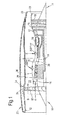
- a ducted fan (or turbofan) gas turbine engine (e.g. a jet engine) generally indicated at 10 has a principal and rotational axis 11.
- the engine 10 comprises, in axial flow series, an air intake 12, a propulsive fan 13, an intermediate pressure compressor 14, a high-pressure compressor 15, combustion equipment 16, a high-pressure turbine 17, an intermediate pressure turbine 18, a low-pressure turbine 19 and a core exhaust nozzle 20.
- a nacelle 21 generally surrounds the engine 10 and defines the intake 12, a bypass duct 22 defined by an inner wall 27 and an outer wall 26, and an exhaust nozzle 23.
- the gas turbine engine 10 works in the conventional manner so that air entering the intake 12 is accelerated by the fan 13 to produce two air flows: a first airflow A into the intermediate pressure compressor 14 of the engine core and a second airflow B which passes through the bypass duct 22 to provide propulsive thrust.
- the intermediate pressure compressor 14 compresses the airflow A directed into it before delivering that air to the high pressure compressor 15 where further compression takes place.
- the compressed air exhausted from the high-pressure compressor 15 is directed into the combustion equipment 16 where it is mixed with fuel and the mixture combusted.
- the resultant hot combustion products then expand through, and thereby drive, the high, intermediate and low pressure turbines 17, 18, 19 before being exhausted through the nozzle 20 to provide additional propulsive thrust.
- the high, intermediate and low-pressure turbines 17, 18, 19 respectively drive the high and intermediate pressure compressors 15, 14 and the fan 13 by suitable interconnecting shafts.
- bleed assemblies 30 are provided to release pressure from an upstream part of a compressor 14,15.
- a gas turbine engine is operating under transient conditions, e.g. when decelerating, it may be necessary to bleed air at high pressure from the core gas flow A through the engine. Operation of a bleed assembly 30 and engine operability are described in " The Jet Engine” 6th Edition, 2005, Rolls-Royce pic, pages 79-80 , and details of such operation will therefore only be briefly mentioned herein.
- the flow of bleed air from the core gas flow into the bypass flow takes place over a substantial pressure drop, and can generate significant noise. It is therefore usual to provide a noise reduction device in, or at the exit of, the bleed assembly 30 between the core gas flow and the bypass duct, for example in a flow duct of the bleed assembly 30.
- a typical measure is to pass the bleed flow through a perforated plate, which is commonly referred to as a pepper pot.
- the pepper pot serves to break the single body of air flowing towards the bypass duct into a large number of smaller jets which promote small-scale turbulence and hence quicker mixing with the main flow through the bypass duct.
- the turbulent mixing means that there is no full recovery of dynamic head, resulting in a reduction in total pressure of the flow. In turn, this allows the velocity of the bleed flow exiting into the bypass duct to be reduced, thereby reducing noise.
- two or more pepper pots can be used in series, in order to break the single large pressure drop into a series of smaller pressure drops.
- Pepper pots are typically made from thin metallic sheets in which holes are formed, for example by laser cutting, and tend to be expensive. If a series of pepper pots are used downstream of a single bleed valve, the cost is multiplied. Also, pepper pots are subjected to high transient pressure drops, and the shock loadings can cause them to deform or disintegrate.
- a device that reduces the noise of a bleed flow and can be manufactured in a cost-effective, reliable, high volume and/or robust manner is desirable.
- a noise attenuation panel for a gas turbine engine comprising a plurality of flow passages. At least one (for example each) flow passage comprises an inlet and an outlet. The flow area through the passage increases downstream of the inlet and may decrease into the outlet.
- the inlet and/or the outlet of each flow passage may be referred to as a throat.
- the flow may experience rapid expansion, and thus turbulent mixing, just downstream of the throat(s). For example, rapid expansion may occur downstream of the inlet where the flow area of the passage increases. Rapid expansion may occur downstream of the outlet outside the noise attenuation panel.
- the inlet may be referred to as an inlet contraction.
- the outlet may be referred to as an outlet (or exit) contraction.
- the throat(s) may be dimensioned such that, in use, the flow through them remains subsonic. Purely by way of example, the Mach number of the flow through the throat(s) (i.e.
- through the inlets or outlet, or any other throats that may be provided in the noise attenuation panel may be less than 0.9, for example less than 0.8, for example less than 0.7, for example less than 0.6, for example less than 0.5, for example less than 0.4, for example less than 0.3, for example less than 0.2, for example less than 0.1, for example less than 0.05.
- Such a noise attenuation panel may provide at least two total pressure drops, for example one just downstream of the flow inlet and one just downstream of the flow outlet for each passage, in a single, compact, low weight unit. Such a panel may be straightforward to manufacture in a reliable, high volume, cost-effective and robust manner.
- the noise attenuation panel may alternatively be referred to as a noise reduction panel, a noise attenuation cassette or a noise reduction cassette.
- each flow passage may increase by at least 10% downstream (for example immediately downstream) of the flow inlet, for example at least 25%, for example at least 50%, for example it may at least double, at least treble, or at least quadruple.
- the flow area may increase (for example by the proportions outlined above) downstream of the inlet within a distance of 0.2mm, 0.5mm, 1 mm, 2mm, 3mm, 4mm, 5mm or 10mm from the flow inlet.
- the flow area of the outlet may be bigger than the flow area of the outlet. This may help to reduce the velocity at the at the flow outlet than would otherwise be the case.
- Each flow passage may change direction at least once between the flow inlet and the flow outlet. Such direction change may, for example, assist with the turbulent mixing.
- Each flow passage may be in the same direction at the inlet and the outlet.
- the flow through the inlet may be in the same direction as the flow through the outlet. This may be achieved, for example, by arranging each flow passage such that it has at least two distinct changes of direction.
- Each bleed flow passage may have at least one change of direction to the right and at least one change of direction to the left. The total angular direction change to the left may be the same as the total angular direction change to the right.
- Each flow passage may comprise three distinct changes of direction between the inlet and the outlet, for example.
- the noise attenuation panel may be generally perpendicular to a longitudinal axis.
- Each flow outlet (for example the centre of each flow outlet) may be offset from the flow inlet (for example from the centre of each flow inlet) in a direction perpendicular to the longitudinal axis.
- the flow inlet and/or the flow outlet of each flow passage may be aligned with the longitudinal axis.
- Arranging flow passages so as to have one or more direction changes and/or such that the flow outlet is offset from the flow inlet may reduce the likelihood of items inadvertently being dropped through a bleed assembly, for example during maintenance. Such items could enter the core of the engine, and require significant further maintenance to ensure that they are not left in the engine where they could lead to significant further damage.
- the noise attenuation panel may be generally perpendicular to a longitudinal axis and comprise a stiffening rib that extends perpendicularly to the longitudinal axis and along a centreline of the noise attenuation panel.
- the noise attenuation panel may be symmetrical about a plane passing through the centre of the stiffening rib and containing the longitudinal axis.
- a stiffening rib may help to reduce the maximum stress in the centre of the panel at the inner (inlet) and outer (outlet) surfaces. This may allow the cassette to be thinner, should that be aerodynamically desirable and/or possible. This may result in still further reductions in weight and/or cost.
- the flow inlets may form a first planar surface.
- the flow outlets may form a second planar surface, which may be offset from the first planar surface.
- the second planar surface may be offset from the first planar surface along a longitudinal axis of the noise attenuation panel.
- the first planar surface and/or the second planar surface may be parallel to each other.
- the first planar surface and/or the second planar surface may be perpendicular to the longitudinal axis of the noise attenuation panel.
- the overall geometry and/or dimensions of the noise attenuation panel may be defined at least in part by the first and second planar surfaces that are offset from each other.
- planar surfaces may assist with the manufacture of noise attenuation panels. For example, it may assist in manufacturing one noise attenuation panel directly on top of another noise attenuation panel more easily, for example using additive layer manufacture.
- each of the flow passages there may be a flow contraction portion followed by a flow expansion portion.
- the flow contraction and flow expansion may be between the end of the region in which the passage increases in flow area downstream of the inlet and the start of the region at which the flow area decreases into the outlet.
- Such a flow contraction portion followed by a flow expansion portion may form a throat.
- the flow may be subsonic through the throat.
- the flow expansion portion may be a rapid increase in area (for example similar to the flow expansion downstream of the inlet) such that, in use, the flow separates in the expansion portion, leading to turbulent mixing.
- the noise attenuation panel may be for use with a bleed flow discharge device.
- the noise attenuation panel may be referred to as a bleed flow noise attenuation panel.
- the flow passing through the noise attenuation panel may be bleed flow.
- Such bleed flow may be taken from a compressor, or a region between the compressor and a combustor of the core of a gas turbine engine, for example.
- a bleed flow discharge device for discharging bleed flow taken from a core flow through a core of a gas turbine engine.
- the bleed flow discharge device comprises a bleed flow duct through which, in use, the bleed flow taken from the core flow passes.
- the bleed flow discharge device comprises a noise attenuation panel as described and/or claimed herein.
- the noise attenuation panel is located within the bleed flow duct, such that the bleed flow passes through the noise attenuation panel before exiting from the bleed flow discharge device.
- the noise attenuation panel may be provided anywhere along the bleed flow duct, including, for example, at the exit to the bleed flow duct.
- the bleed flow duct may have a simple open hole at its outlet, or may be provided with a bleed flow outlet panel.
- a bleed flow outlet panel may be provided at the outlet to the bleed flow discharge device through which, in use, the bleed flow exits the bleed flow discharge device.
- Such an outlet panel may be provided downstream of the noise attenuation panel relative to the bleed flow.
- the bleed flow outlet panel and the noise attenuation panel may be separate units.
- the bleed flow outlet panel and the noise attenuation panel may be a single unit.
- the bleed flow outlet panel and the noise attenuation panel may be formed as a single continuous part, with one panel merging directly into the other panel.
- the bleed flow outlet panel and the noise attenuation panel may be integrally formed.
- the flow passage outlets of the noise attenuation panel may form (or be) inlets to corresponding exit passages of the bleed flow outlet panel.
- the a bleed flow outlet panel may comprise exit passages, and the number of exit passages may be the same as the number of flow passages in the noise attenuation device.
- a bleed flow outlet unit arranged to attenuate noise and direct flow.
- the flow may be bleed flow that may be bled from a core flow through a core of a gas turbine engine, the bleed flow outlet unit being a unitary part comprising: a noise attenuation portion comprising a noise attenuation panel as described and/or claimed herein; and a bleed flow outlet portion.
- the bleed flow outlet portion may comprise bleed flow outlet passages.
- Each flow passage of the noise attenuation portion may be fluidly connected to a single respective bleed flow outlet passage, such that each flow passage of the noise attenuation portion forms a continuous flow passage with its respective bleed flow outlet passage.
- a further consideration when discharging bleed flow from a bleed assembly may be that the bleed flow is typically at a significantly higher temperature than the flow into which it is being discharged. This can, in some cases, cause thermal damage if the higher temperature bleed flow impinges on surfaces that are not designed to tolerate such elevated temperatures.
- Providing a bleed flow outlet panel to the bleed flow discharge device may, in some cases, allow the bleed flow to be directed and/or more effectively mixed with the flow into which it is discharged. This may help to alleviate any problems associated with thermal damage caused by the higher temperature bleed flow. Any such bleed flow outlet panel should have low blockage so as to minimize the size and/or weight of the bleed assembly that is required for a given bleed flow rate.
- a bleed flow discharge device includes a bleed flow outlet panel (which may be integrated with the noise attenuation panel, as explained above), the bleed flow outlet panel may take any suitable form.
- the bleed flow outlet panel may comprise passages, which may be referred to as exit passages because they are the passages through which the bleed flow exits the bleed flow discharge device.
- a bleed flow outlet panel Various optional features relating to a bleed flow outlet panel are now presented. It will be appreciated that such optional features may be relevant where an arrangement includes a bleed flow outlet panel. However, as will be appreciated from the disclosure herein, various arrangements in accordance with the invention may not include such a bleed flow outlet panel and/or a bleed flow outlet panel may itself only be optional to some arrangements of the invention. Any of the optional features presented herein in relation to a bleed flow outlet panel may be included in a bleed flow outlet panel that is integral with a noise attenuation panel, or separate from a noise attenuation panel, for example in a bleed flow discharge device.
- a bleed flow outlet panel may comprise a perimeter edge that fits within the outlet of the bleed flow discharge device and is formed around a major axis of the bleed flow outlet panel, and a plurality of exit passages.
- the exit passages may be formed in at least two distinct regions of the bleed flow outlet panel, each region comprising a plurality of adjacent exit passages.
- the exit passages in a first region may be arranged to direct the bleed flow, in use, in a direction that is substantially aligned with the major axis of the bleed flow outlet panel.
- the exit passages in a second region may be arranged to direct the bleed flow, in use, in a direction that, when projected onto a plane perpendicular to the major axis and containing the perimeter edge, points towards the closest point on the perimeter edge.
- the planform shape of a bleed flow outlet panel may be defined as the shape of the bleed flow outlet panel when viewed along its major axis.
- the perimeter edge may define a generally planar structure.
- the bleed flow outlet panel may be a generally planar structure.
- the exit passages in a second region may be arranged to direct the bleed flow, in use, in a direction that, when projected onto the generally planar structure points towards the closest point (which may be referred to as the local closest point) on the perimeter edge.
- the bleed flow outlet panel may comprise a perimeter edge formed around a major axis of the bleed flow outlet panel and defining its planform shape.
- the bleed flow outlet panel may comprise a plurality of exit passages, the exit passages being formed in at least two distinct regions of the bleed flow outlet panel, each region comprising a plurality of adjacent exit passages.
- the exit passages in a first region may be arranged to direct the bleed flow, in use, in a direction that has a greater component in the direction of the major axis than do the exit passages in the second region.
- bleed flow outlet may be aligned with longitudinal axis of noise attenuation panel.
- exit passages of a bleed flow outlet panel being arranged to direct bleed flow in a certain direction, this may mean that those exit passages may be said to point in that direction.
- a bleed flow discharge device may be arranged for use with a turbofan gas turbine engine having a bypass duct arranged around the engine core, with the bypass duct having a bypass flow passing therethrough in use.
- the exit passages of the bleed flow outlet panel may be arranged to discharge the bleed flow into the bypass duct and the second region of the bleed flow outlet panel may be generally downstream of the first region relative to the direction of the bypass flow in use.
- the second region of the bleed flow outlet panel (where present) may be generally downstream of the first region relative to the direction of the flow into which the bleed flow is discharged.
- a bleed flow outlet panel may thus have exit passages formed in at least two distinct regions of the bleed flow outlet panel, each region comprising a plurality of adjacent exit passages.
- the exit passages in the second region of a bleed flow outlet panel may be said to point in a direction that has a component that points away from the major axis.
- the exit passages in the second region may be said to point in a direction that has a component that points towards the closest point on the perimeter edge.
- the absolute angle of the exit passages (for example relative to each other) may vary in the second region, for example depending on the angular position around the major axis and/or the direction from a given exit to the closest position on the perimeter edge of the bleed flow outlet.
- the first region may be defined by a first angular segment of a bleed flow outlet panel.
- the second region may be defined by a second angular segment of the bleed flow outlet panel.
- an angular segment may be a segment or region of the outlet panel between two walls diverging from a central region of the outlet panel to the perimeter edge.
- All of the exit passages of a bleed flow outlet panel may be formed in either the first region or the second region.
- the exit passages in the second region may be arranged to direct the bleed flow, in use, in a direction that has a major component in the direction of the major axis of the bleed flow outlet panel. All exit passages (for example exit passages in both the first region and the second region) may be said to have a major component that points in the direction of the major axis.
- a major component may mean, for example, that at least 50%, for example at least 60%, for example at least 70%, for example at least 80%, for example at least 90%, of the flow rate through an exit passage is in the direction of the major axis.
- a bleed flow outlet panel may comprise two walls that are spaced apart from each other and separate the first region from the second region. Each wall may extend across the thickness of the bleed flow outlet panel, i.e. across the dimension that extends in the direction of the major axis. The wall may extend from the perimeter edge to an inner region or innermost extent of the bleed flow outlet panel.
- the perimeter edge, and thus the plan form shape of a bleed flow outlet panel may take any desired shape.
- the perimeter edge of the bleed flow outlet panel may comprise a first curved portion and a second curved portion.
- the first curved portion and/or the second curved portion may be, for example, segments of a circle, for example semi-circular.
- the perimeter edge of a bleed flow outlet panel may be an elongate shape.
- Such an elongate shape may have first and second curved portions joined together by a first side edge and a second side edge.
- the first and second side edges may be straight, or may themselves comprise a curve, or a curved portion.
- the perimeter edge may be a racetrack shape, an oval shape, or a rectangle with curves (such as semicircles) at either end, or any other desired shape.
- the first region may be defined at least in part by at least a part of the first curved portion (for example a part or all of the first curved portion).
- the first region may be defined at least in part by first and second dividing walls extending into the bleed flow outlet panel from first and second points on the first curved portion, including from first and second ends of the first curved portion.
- the bleed flow outlet panel may extend in a direction that is substantially perpendicular to the local perimeter edge.
- the first and second dividing walls may extend in a direction that is parallel to the major axis of the panel.
- the second region may be defined by the first and second dividing walls, the second curved portion, the first side edge, and the second side edge in arrangements including these features.
- the second region may itself be split into two, three, four or more sub-regions.
- Such sub-regions may be formed by further dividing walls within the second region, for example, third, fourth or fifth dividing walls.
- Such additional dividing walls may provide structural strength and/or rigidity to the structure.
- the first curved portion When in use, the first curved portion may be positioned at a downstream end of the panel relative to a main flow into which the bleed flow though a bleed flow outlet panel exits.
- the second curved portion When in use, the second curved portion may be positioned at an upstream end of the panel relative to a main flow into which the bleed flow exits.
- the total flow area of the exit passages in the second region may be greater than the total flow area of the exit passages in the first region.
- the exit passages in the second region may be said to direct the bleed flow in a direction that, when projected onto the plane of the outlet panel, is locally perpendicular to the closest point on the perimeter edge of the outlet panel (that is, perpendicular to a tangent to the closest point on the perimeter edge).
- the perimeter edge of the second region comprises a straight portion
- the exit passage(s) for which the straight portion is their closest point on the perimeter edge may point in a direction that is perpendicular to that straight portion.
- the perimeter edge of the second region comprises a segment of a circle
- the exit passage(s) for which the segment of the circle is their closest point on the perimeter edge may point in a direction that is along a radius of that circular portion.
- exit passages in a bleed flow outlet panel may take any suitable form, for example any suitable size and/or shape.
- the exit passages may be formed by vanes. Such vanes may be formed inside the perimeter edge of the outlet panel.
- each region may comprise at least two offset walls that are offset from the perimeter edge, and each exit passage may be defined at least in part by adjacent offset walls or by the perimeter edge and the offset wall immediately adjacent the perimeter edge.
- the distance between an offset wall and an adjacent offset wall or perimeter edge may be constant around the entire length of the wall.
- the exit passages of the first region may be arranged to direct the bleed flow within 10 degrees, for example within 5 degrees, of the major axis of the bleed flow outlet panel, for example within 4 degrees, 3 degrees, 2 degrees or 1 degree of the major axis.
- the exit passages in the second region may be arranged to direct the bleed flow at an angle in the range of from 5 degrees to 40 degrees from the major axis of the bleed flow outlet, for example in the range of from 10 degrees to 35 degrees, for example in the range of from 15 degrees to 30 degrees, for example in the range of from 20 degrees to 25 degrees.
- Each exit passage in the second region may be arranged to direct the bleed flow at substantially the same angle from the major axis as the other exit passages in the second region.
- the magnitude of the component of the bleed flow pointing towards the perimeter edge of the outlet panel may be the same for each exit passage in the second region in some arrangements.
- the absolute direction of the bleed flow at exit from the exit passages may vary around the second region, for example depending on angular position around the major axis of the bleed flow outlet panel.
- the second region may extend around at least 180 degrees about the major axis, and the bleed flow through exit passages that are separated by 180 degrees may have components projected onto the plane of the outlet panel that are in opposite directions.
- the optional bleed flow outlet panel may take a number of different forms.
- a turbofan gas turbine engine comprising a core engine through which core flow passes in use; a bypass duct surrounding the core engine and through which bypass flow passes in use; and a bleed flow assembly for allowing bleed flow to be selectively bled from the core flow to the bypass flow in use.
- the bleed flow assembly comprises a bleed valve in communication with the core flow and arranged to be selectively openable to allow bleed flow to be bled from the core flow.
- the bleed flow assembly also comprises at least one of a noise attenuation panel, a bleed flow discharge device, and a bleed flow outlet unit as described and/or claimed herein.
- the noise attenuation panel, bleed flow discharge device, and/or bleed flow outlet unit is arranged downstream of the bleed valve relative to the bleed flow, such that, in use, bleed flow that is selectively bled from the core flow through the bleed valve passes through the noise attenuation panel, bleed flow discharge device, and/or bleed flow outlet unit before being discharged into the bypass flow.
- the bleed valve may be said to be in selective fluid communication with the core flow.
- the bleed flow discharge device may be said to be in fluid communication with the bleed valve.
- the bleed flow discharge device and the bleed valve may be referred to as a bleed assembly.
- the noise attenuation panel may be achiral.
- the noise attenuation panel may comprise at least one plane of symmetry.
- a mirror image of the noise attenuation panel may be geometrically identical to the noise attenuation panel itself.
- a bleed flow outlet panel and a noise attenuation panel are integrally formed as a single unit
- that single unit may be achiral and/or have at least one plane of symmetry.
- a mirror image of the single unit may be geometrically identical to the single unit itself.
- each noise attenuation panel comprises a first planar surface offset from a second planar surface along a longitudinal axis.
- Each new layer formed in the manufacture is offset from the previously manufactured layer in a manufacturing direction that corresponds to the longitudinal direction of the noise attenuation panel. All of the layers of one noise attenuation panel may be deposited before any of the layers of a subsequent noise attenuation panel are deposited.
- the first planar surface of one noise attenuation panel is manufactured adjacent the first planar surface of an adjacent noise attenuation panel and/or the second planar surface of one noise attenuation panel is manufactured adjacent the second planar surface of an adjacent noise attenuation panel.
- the geometry of one noise attenuation panel is built as a mirror image of the geometry of adjacently manufactured noise attenuation panel.
- the mirror image is about the plane at which the two adjacent parts are joined (and ultimately separated from each other).
- the mirrored parts are geometrically identical to each other.
- two adjacent parts may be said to be upside down relative to each other.
- two parts that are separated from each other by another panel i.e. adjacent but one panels
- the at least two parts may be separated from each other, for example by electro discharge machining (EDM).
- EDM electro discharge machining
- Manufacturing noise attenuation panels (or other components, such as bleed flow outlet units comprising a noise attenuation panel and a bleed flow outlet panel as described and/or claimed herein for example) in this manner may allow the manufacture of one component to be completed (at least in terms of the ALM process) before the manufacture of another component is started. All of the layers of one noise attenuation panel may be deposited before any of the layers of a subsequent noise attenuation panel are deposited. This may be advantageous if, for example, the process were to fail part way through, because at least those parts for which the ALM process has been completed could be further processed as required in order to become finished parts.
- the noise attenuation panel may be in accordance with any noise attenuation panel described and/or claimed herein.
- the first planar face may comprise flow inlets and the second planar face may comprise corresponding flow outlets, or vice versa.
- ALM additive layer manufacture
- DLD direct laser deposition
- the method described and claimed herein for manufacturing at least two identical achiral noise attenuation panels may be used to manufacture at least two identical achiral components of any form.
- at least two achiral units comprising a noise attenuation panel and a bleed flow outlet panel may be manufactured using the ALM method described and claimed herein in relation to the manufacture of noise attenuation panels.
- Each component may comprises a first planar surface offset from a second planar surface along a longitudinal axis.
- Each new layer formed in the manufacture is offset from the previously manufactured layer in a manufacturing direction that corresponds to the longitudinal direction of the component. All of the layers of one component may be deposited before any of the layers of a subsequent component are deposited.
- the first planar surface of one component is manufactured adjacent the first planar surface of an adjacent component and/or the second planar surface of one component is manufactured adjacent the second planar surface of an adjacent component.
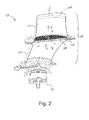
- a bleed assembly 130 comprises a noise attenuation panel 300 according to an example of the invention.
- the bleed assembly 130 comprises a bleed valve 34 which communicates at one end with the respective compressor 14, 15 (shown in Figure 1 ) and is provided at its other end with a bleed flow discharge device 100.
- the noise attenuation panel 300 may be said to be part of the bleed flow discharge device 100.
- part of the core engine air flow A may be diverted through the bleed assembly 130 by opening the bleed valve 34 so that the bleed air flow passes from the respective compressors 14, 15 to be discharged into the bypass duct 22 through the bleed flow discharge device 100.
- a bleed assembly 130 and/or noise attenuation panel 300 such as that described herein in relation to Figures 2 to 8 may be used with any gas turbine engine, such as the gas turbine engine 10 shown in Figure 1 .
- the bleed flow assemblies shown by way of example in Figure 1 are labelled 30/130, to indicate that the gas turbine engine 10 of Figure 1 may comprise a bleed assembly 130 and/or bleed flow discharge device 100 and/or noise attenuation panel 300 in accordance with the invention, and thus may itself be in accordance with the invention.
- the bleed flow discharge device 100 comprises a bleed flow duct 120 and the noise attenuation panel 300.
- the outlet 400 of the bleed flow discharge device 100 is an open outlet.
- the outlet 400 could be provided with a bleed flow outlet panel, which may be formed as an integral part of the noise attenuation panel 300.
- the position of the noise attenuation panel 300 within the duct 120 shown in Figure 2 is by way of example only. The noise attenuation panel 300 may be moved closer to (or even at) the outlet 400, or closer to the bleed valve 34.
- FIG. 3 An example of a portion of a noise attenuation panel 300 is shown in more detail in Figure 3.
- Figure 3 only shows a portion of a noise attenuation panel 300, so as to show the geometry in greater detail.
- the noise attenuation panel 300 comprises a plurality of flow passages 310.
- Each flow passage 310 comprises a flow inlet 312 and a flow outlet 314.
- bleed flow C which may have been bled from a compressor 14, 15 through a bleed valve 34 as shown in Figure 2 , passes into the inlets 312.
- the area of the bleed flow outlet 314 may be greater than the area of the bleed flow inlet 312, as in the Figure 3 example. This may help to keep the static pressure at the flow outlet 314 similar to the static pressure at the flow inlet 312, for example. However, in other arrangements the area of the bleed flow outlet 314 may be the same as the area of the bleed flow inlet 312, or the area of the bleed flow outlet 314 may be less than the area of the bleed flow inlet 312.
- the flow area of the bleed flow C is reduced by the noise attenuation panel 300 at entry, and so the flow accelerates as it enters the flow inlets 312. However, the flow remains subsonic through the inlets 312.
- each flow passage 310 Downstream of the flow inlet 312, the area of each flow passage 310 increases, as shown by the region 316 in Figure 3 . Accordingly, the flow inlets 312 may be referred to as throats.
- the expansion region 316 may be rapid expansion, for example occurring over a distance of less than 5mm, for example less than 2mm, for example less than 1 mm, for example less than 0.5mm, for example less than 0.2mm.
- the flow in the flow passages 310 may become turbulent in the expansion region 316, for example due to flow separation just downstream of the inlet 312. The turbulent flow results in energy dissipation through the kinetic energy of the flow being converted into heat energy.
- each outlet 314 Upstream of each outlet 314 is a flow contraction portion 318. Thus, the flow area decreases into the outlet 314.
- the outlet may be referred to as a throat. Again, the flow remains subsonic through the outlets 314.
- the bleed flow D After the bleed flow D exits though the outlets 314, it undergoes rapid expansion. As such, the bleed flow experiences further mixing and loss of total pressure due to lack of dynamic head recovery after it passes through the outlets 314.
- the bleed flow may pass out of the outlets 314 into an upper portion of the bleed flow duct 120, as shown by way of example in Figure 1 .
- the bleed flow D may pass from the bleed flow outlets directly into a bleed flow outlet panel 200.
- the first and second controlled total pressure reductions generated through the bleed flow mixing at exit from the inlet 312 (in expansion region 316) and exit from the outlet 314 (outside the noise attenuation panel 300) mean that the total pressure of the bleed flow E at the outlet 400 of the bleed flow discharge device 100 is lower than would otherwise be the case. This means that the flow E has less energy as it is ejected from the outlet 400, for example into the bypass flow B of a gas turbine engine. In turn this reduces the strength of a plume exiting the bleed flow discharge device 100, and the noise generated from such a plume.
- the direction of the bleed flow changes as it passes through the noise attenuation panel 300.
- the direction of the bleed flow C at inlet 312 may be the same as the direction of the bleed flow D at the outlet 314, as in the Figure 3 example.
- the flow turning through the bleed flow passage 310 may assist in mixing the bleed flow in a short distance, for example in the direction of the longitudinal axis Z-Z of the noise attenuation panel 300.
- the noise attenuation panel 300 may be regarded as a relatively thin panel that extends generally perpendicularly to the longitudinal axis Z-Z.
- the direction changes 322, 324, 326 may be arranged so as to prevent a clear line of sight through a flow passage 310, from the inlet 312 to the outlet 314 or vice versa.
- components such as fixings, such as nuts, bolts and washers, cannot pass through the noise attenuation panel 300, for example during build and/or maintenance.
- this may be achieved by ensuring that any line of sight through the flow passages were thinner than the thinnest component that could fall through them.
- Figure 5 shows a cross section through a noise attenuation panel 300 in a plane that passes through a rib 330, which may be a stiffening rib 330.
- the rib 330 is also shown in Figure 2 . As shown most clearly in Figure 2 , such a rib 330 may extend along a centreline of the noise attenuation panel 300. The rib 330 may extend in a direction that is perpendicular to the longitudinal axis Z-Z of the noise attenuation panel 300.
- a noise attenuation panel 300 may comprise no ribs 330, one rib 330, or more than one rub 330, for example two ribs 330 as in the Figure 2 example.
- the rib 330 may help to reduce the maximum stress that occurs at the centre of the panel 300, for example at its inner and outer surfaces. This may allow the panel 300 to be thinner and/or lighter and/or less expensive.
- a rib 330 may take any suitable shape including, by way of example only, a simple oblong-shaped bar or an I-beam. In the example shown in Figure 5 , the rib 330 has portions 332, 334 on its upper and lower surface that are shaped so as to reduce the amount of material in the rib 330. This may be beneficial in reducing the potential damage caused by thermal shock, which may otherwise occur when the panel 300 is suddenly exposed to the relatively hot bleed flow gasses.
- the hot gasses could cause stress in the panel 300 due to parts of different thicknesses heating up and/or expanding at different rates.
- Such thermal shock damage may be reduced by minimizing the difference in thickness between the rib 330 and the passage elements 340 that form the flow passages 310, for example by removing material, as illustrated in regions 332, 334 in Figure 5 .
- the noise attenuation panel 300 may be achiral. As such, a mirror image of the noise attenuation panel 300 may have the same geometry as the noise attenuation panel itself.
- the panel 300 is achiral, and has at least one plane of symmetry, including for example one that contains both the longitudinal axis Z-Z and the centreline along which the stiffening rib 330 extends.
- a noise attenuation panel 300 may have one or more planes of symmetry.
- Arranging the noise attenuation panel 300 such that it has the same geometry as its mirror may be advantageous during manufacture. For example, it may allow one panel 300 to be manufactured on top of, and upside down relative to, another panel 300. This may be useful if more than one panel 300 is to be manufactured using additive layer manufacture (ALM), such as direct laser deposition (DLD).
- ALM additive layer manufacture
- DLD direct laser deposition
- an achiral noise attenuation panel 300 may be manufactured using ALM, with each layer being deposited in a plane that is perpendicular to the longitudinal axis Z-Z. As such, the panel 300 may be said to be manufactured in a horizontal orientation, that is with its main planes having the inlets 312 and the outlets 314 arranged horizontally during the manufacturing process.
- the longitudinal extent of the noise attenuation panel 300 (which may be referred to as its thickness, in the direction of the longitudinal axis Z-Z) may be defined by surfaces that lie in planes 350, 360.
- the surfaces 342 of the passage elements 340 and the surfaces 336 of the rib 330 (where present) that define the flow inlets 312 may all lie in a plane 350.
- the surfaces 344 of the passage elements 340 and the surfaces 338 of the rib 330 (where present) that define the flow inlets 314 may all lie in a plane 360.
- the two planes 350, 360 may be parallel, as in the examples of Figures 3 to 7 .
- Such planes 350, 360 defining the thickness of the panel 300 may allow one panel 300 to be built on top of another panel 300, with the two adjacent panels 300 flipped over (or upside down) relative to each other such that corresponding planes 350, 360 of adjacent panels 300 are coplanar during manufacture. This may be particularly beneficial during manufacture, because it means that all of the material for one panel 300 is deposited before any material for the next part is deposited. Accordingly, in the event of failure of the ALM machine (which may occur after hours or even days), only that panel that is currently being manufactured would become scrap, and all previously manufactured panels could be used. Of course, a noise attenuation panel 300 is an example of many components for which this is true.
- Figure 6 is a cross sectional close-up of the region 370 at the edge of the noise attenuation panel 300 where it attaches to the bleed flow duct 120 of the bleed flow discharge device 100.
- the arrangement shown in Figure 6 is merely a non-limitative example of a great many attachment arrangements that could be used.
- the edge portion 375 of the panel 300 is simply welded 376, 378 to a connection plate 125 of the bleed flow duct 120. Accordingly, the relatively complex geometry of the noise attenuation panel 300 and the relatively straightforward geometry of the bleed flow duct 120 may be manufactured separately. Thus, for example, a relatively expensive ALM process could be used to manufacture the panel 300, but not the bleed flow duct 120.
- Figure 7 shows a bleed flow outlet unit 500 arranged to attenuate noise generated by a bleed flow and direct the bleed flow at the outlet of a bleed flow discharge device 100.
- the bleed flow outlet unit 500 comprises a noise attenuation portion 300 and a bleed flow outlet portion 200.
- the noise attenuation portion 300 and the bleed flow outlet portion 200 may be unitary and/or continuous, as in the Figure 7 example.
- the noise attenuation portion 300 may be substantially the same as the noise attenuation panel 300 described elsewhere herein, and thus like features are given the same reference numeral as in Figures 2 to 6 and will not be described further in relation to Figure 7 .
- the rapid expansion of the bleed flow after it passes through the outlets 314 of the noise attenuation portion 300 occurs in expansion region 319 at the inlet to the bleed flow outlet portion 200.
- Figure 7 shows an example in which each flow passage 310 of the noise attenuation portion 300 is directly fluidly connected to one (and only one, in the case of Figure 7 ) bleed flow outlet passage 212/222 of the bleed flow outlet portion 200 (see also Figure 8 ).
- the bleed flow outlet portion 200 is arranged to ensure that the bleed flow E at exit from the bleed flow outlet unit 500 (and thus from a bleed flow assembly 130 in which it may be used) is in the desired direction and/or experiences appropriate mixing with the flow into which it is exhausted.
- the bleed flow outlet passages 212/222 may be arranged as desired to achieve such mixing and/or desired flow direction.
- FIG. 8 An example of the a bleed flow outlet portion 200 is shown in schematic form in Figure 8 .
- the bleed flow outlet portion of Figure 8 is a substantially planar structure having its major plane perpendicular to a major axis Y-Y.
- the major axis Y-Y may be substantially aligned with the radial axis of a gas turbine engine 10, and with the longitudinal axis Z-Z of the noise attenuation portion 300 (not shown in Figure 8 as it is enclosed within the bleed flow duct 120).
- the bleed flow outlet portion 200 of Figure 8 comprises a first region 210 and a second region 220.
- the first region 210 and the second region 220 are separated from each other by a first wall 230 and a second wall 240.
- Each of the first wall 230 and the second wall 240 extends from a perimeter edge (which may be referred to as a perimeter edge wall) 250 to a centre (or centre region) 260 of the bleed flow outlet portion 200.
- the first region 210 comprises exit passages 212 and the second region 220 comprises exit passages 222.
- the bleed flow exits the bleed flow discharge device 100 through the exit passages 212, 222 in the bleed flow outlet portion 200 in such an arrangement.
- the exit passages 212 point in a direction P that is substantially parallel to the major axis Y-Y of the bleed flow outlet panel 200. As such, the bleed flow is discharged through the exit passages 212 of the bleed flow outlet portion 200 in a direction that is substantially parallel to the major axis Y-Y.
- the exit passages 222 in the second region point in a directions Q that have a component that points towards the perimeter edge 250 (that is, the closest point on the perimeter edge 250 to the respective exit passage 222), and a component that points in the direction of the major axis Y-Y.
- the bleed flow is discharged through the exit passages 222 of the bleed flow outlet portion 200 in directions Q that have a component that points towards the perimeter edge 250, and a component that points in the direction of the major axis Y-Y.
- the absolute Q of the flow passing through the exit passages 222 in the second region 220 may be different for different exit passages 222 depending on, for example, the direction to the closest point on the perimeter edge 250.
- the absolute direction of the flow passing through an individual exit passage 222 of the second region 220 may be different at different points within the exit passage 222, for example if the individual exit passage has a curved shape in planview (that is, a curved shape when viewed from a direction aligned with the major axis Y-Y).
- the first region 210 (for example the centroid of the first region 210) may be downstream of the second region 220 (for example the centroid of the second region 220) relative to the bypass flow B into which the bleed flow is discharged through the exit passages 212, 222.
- the bleed flow exiting in the direction P substantially parallel to (or more parallel to) the major axis Y-Y may be at the downstream side or region of the bleed flow outlet portion 200 relative to the bypass flow. This may reduce the likelihood of the bleed flow (for example a plume resulting from the bleed flow) attaching to the inner surface 27 of the bypass duct 22, thereby reducing the likelihood of thermal damage to the inner surface.
- the perimeter edge 250 (and thus the planform shape) of the bleed flow outlet portion 200 is a stadium, or racetrack shape, i.e. it has two offset straight edges joined together by curves which, in the example of Figure 8 are semicircles.
- the perimeter edge 250 could have any desired shape.
- the perimeter edge 250 could be a rounded rectangle, circle, rectangle, ellipse, oval or any other suitable shape, such as any suitable elongate shape.
- bleed flow outlet portion 200 is described as being integral with the noise attenuation portion 300 in a bleed flow outlet unit 500, it will be appreciated that the bleed flow outlet portion 200 could be provided as a bleed flow outlet panel 200 that is separate to (and complimentary to) a noise attenuation panel 300 as described elsewhere herein.
- a bleed flow outlet unit 500 may be manufactured using ALM/DLD, as described above in relation to the noise attenuation device 300 in isolation.
- noise attenuation panel 300 and bleed flow outlet unit 500 have been described herein in relation to discharging bleed flow into a bypass flow of a turbofan gas turbine engine, such a noise attenuation panel 300 and/or bleed flow outlet unit 500 may also be used where a bleed flow exhausts overboard from an engine into an external flow.
- a bleed flow may exhaust to atmospheric conditions external to the engine with the discharge device disclosed herein.
- the present disclosure may be applied to a land based gas turbine, e.g. an aero-derivative or other gas turbine, for which a bypass duct may not be present and the bleed flow may be exhausted to atmospheric conditions.
- the noise attenuation panel 500 and bleed flow discharge device 130 with which it is used may exhaust into any flow field, including but not limited to discharge into a bypass duct.
Landscapes
- Engineering & Computer Science (AREA)
- Chemical & Material Sciences (AREA)
- Combustion & Propulsion (AREA)
- Mechanical Engineering (AREA)
- General Engineering & Computer Science (AREA)
- Physics & Mathematics (AREA)
- Fluid Mechanics (AREA)
- Life Sciences & Earth Sciences (AREA)
- Sustainable Development (AREA)
- Structures Of Non-Positive Displacement Pumps (AREA)
- Exhaust Silencers (AREA)
Abstract
Description
- This disclosure relates to a flow discharge device and a noise attenuation device for a flow discharge device. The disclosure may be concerned with discharging bleed air in gas turbine engine, for example for bleeding air from a compressor to a bypass duct.
- Referring to
Figure 1 , a ducted fan (or turbofan) gas turbine engine (e.g. a jet engine) generally indicated at 10 has a principal and rotational axis 11. Theengine 10 comprises, in axial flow series, anair intake 12, apropulsive fan 13, anintermediate pressure compressor 14, a high-pressure compressor 15,combustion equipment 16, a high-pressure turbine 17, anintermediate pressure turbine 18, a low-pressure turbine 19 and acore exhaust nozzle 20. Anacelle 21 generally surrounds theengine 10 and defines theintake 12, abypass duct 22 defined by aninner wall 27 and an outer wall 26, and anexhaust nozzle 23. - The
gas turbine engine 10 works in the conventional manner so that air entering theintake 12 is accelerated by thefan 13 to produce two air flows: a first airflow A into theintermediate pressure compressor 14 of the engine core and a second airflow B which passes through thebypass duct 22 to provide propulsive thrust. Theintermediate pressure compressor 14 compresses the airflow A directed into it before delivering that air to thehigh pressure compressor 15 where further compression takes place. - The compressed air exhausted from the high-
pressure compressor 15 is directed into thecombustion equipment 16 where it is mixed with fuel and the mixture combusted. The resultant hot combustion products then expand through, and thereby drive, the high, intermediate andlow pressure turbines nozzle 20 to provide additional propulsive thrust. The high, intermediate and low-pressure turbines intermediate pressure compressors fan 13 by suitable interconnecting shafts. - During engine operation and particularly when changing rotational speed at low power it is important to ensure that the pressure ratio across each
compressor engine 10 can surge and flow through theengine 10 breaks down. This can cause damage to the engine's components as well as aircraft handling problems. - To maintain a preferred pressure difference across a
compressor compressor compressor - The flow of bleed air from the core gas flow into the bypass flow takes place over a substantial pressure drop, and can generate significant noise. It is therefore usual to provide a noise reduction device in, or at the exit of, the bleed assembly 30 between the core gas flow and the bypass duct, for example in a flow duct of the bleed assembly 30. A typical measure is to pass the bleed flow through a perforated plate, which is commonly referred to as a pepper pot. The pepper pot serves to break the single body of air flowing towards the bypass duct into a large number of smaller jets which promote small-scale turbulence and hence quicker mixing with the main flow through the bypass duct. The turbulent mixing means that there is no full recovery of dynamic head, resulting in a reduction in total pressure of the flow. In turn, this allows the velocity of the bleed flow exiting into the bypass duct to be reduced, thereby reducing noise.
- In order to avoid a single large pressure drop and sudden expansion from the high pressure core flow to the bypass flow, two or more pepper pots can be used in series, in order to break the single large pressure drop into a series of smaller pressure drops.
- Pepper pots are typically made from thin metallic sheets in which holes are formed, for example by laser cutting, and tend to be expensive. If a series of pepper pots are used downstream of a single bleed valve, the cost is multiplied. Also, pepper pots are subjected to high transient pressure drops, and the shock loadings can cause them to deform or disintegrate.
- It is therefore desirable to be able to reduce the noise generated by a bleed flow in a more efficient and/or compact and/or lower weight manner. Additionally or alternatively, a device that reduces the noise of a bleed flow and can be manufactured in a cost-effective, reliable, high volume and/or robust manner is desirable.
- According to an aspect, there is provided a noise attenuation panel for a gas turbine engine comprising a plurality of flow passages. At least one (for example each) flow passage comprises an inlet and an outlet. The flow area through the passage increases downstream of the inlet and may decrease into the outlet.
- The inlet and/or the outlet of each flow passage may be referred to as a throat. The flow may experience rapid expansion, and thus turbulent mixing, just downstream of the throat(s). For example, rapid expansion may occur downstream of the inlet where the flow area of the passage increases. Rapid expansion may occur downstream of the outlet outside the noise attenuation panel. The inlet may be referred to as an inlet contraction. The outlet may be referred to as an outlet (or exit) contraction. The throat(s) may be dimensioned such that, in use, the flow through them remains subsonic. Purely by way of example, the Mach number of the flow through the throat(s) (i.e. through the inlets or outlet, or any other throats that may be provided in the noise attenuation panel) may be less than 0.9, for example less than 0.8, for example less than 0.7, for example less than 0.6, for example less than 0.5, for example less than 0.4, for example less than 0.3, for example less than 0.2, for example less than 0.1, for example less than 0.05.
- Such a noise attenuation panel may provide at least two total pressure drops, for example one just downstream of the flow inlet and one just downstream of the flow outlet for each passage, in a single, compact, low weight unit. Such a panel may be straightforward to manufacture in a reliable, high volume, cost-effective and robust manner. The noise attenuation panel may alternatively be referred to as a noise reduction panel, a noise attenuation cassette or a noise reduction cassette.
- The flow area of each flow passage may increase by at least 10% downstream (for example immediately downstream) of the flow inlet, for example at least 25%, for example at least 50%, for example it may at least double, at least treble, or at least quadruple. By way of example, the flow area may increase (for example by the proportions outlined above) downstream of the inlet within a distance of 0.2mm, 0.5mm, 1 mm, 2mm, 3mm, 4mm, 5mm or 10mm from the flow inlet.
- The flow area of the outlet may be bigger than the flow area of the outlet. This may help to reduce the velocity at the at the flow outlet than would otherwise be the case.
- Each flow passage may change direction at least once between the flow inlet and the flow outlet. Such direction change may, for example, assist with the turbulent mixing.
- Each flow passage may be in the same direction at the inlet and the outlet. In use, the flow through the inlet may be in the same direction as the flow through the outlet. This may be achieved, for example, by arranging each flow passage such that it has at least two distinct changes of direction. Each bleed flow passage may have at least one change of direction to the right and at least one change of direction to the left. The total angular direction change to the left may be the same as the total angular direction change to the right.
- Each flow passage may comprise three distinct changes of direction between the inlet and the outlet, for example.
- The noise attenuation panel may be generally perpendicular to a longitudinal axis. Each flow outlet (for example the centre of each flow outlet) may be offset from the flow inlet (for example from the centre of each flow inlet) in a direction perpendicular to the longitudinal axis. The flow inlet and/or the flow outlet of each flow passage may be aligned with the longitudinal axis.
- Arranging flow passages so as to have one or more direction changes and/or such that the flow outlet is offset from the flow inlet may reduce the likelihood of items inadvertently being dropped through a bleed assembly, for example during maintenance. Such items could enter the core of the engine, and require significant further maintenance to ensure that they are not left in the engine where they could lead to significant further damage.
- The noise attenuation panel may be generally perpendicular to a longitudinal axis and comprise a stiffening rib that extends perpendicularly to the longitudinal axis and along a centreline of the noise attenuation panel. The noise attenuation panel may be symmetrical about a plane passing through the centre of the stiffening rib and containing the longitudinal axis.
- A stiffening rib may help to reduce the maximum stress in the centre of the panel at the inner (inlet) and outer (outlet) surfaces. This may allow the cassette to be thinner, should that be aerodynamically desirable and/or possible. This may result in still further reductions in weight and/or cost.
- The flow inlets may form a first planar surface. The flow outlets may form a second planar surface, which may be offset from the first planar surface. The second planar surface may be offset from the first planar surface along a longitudinal axis of the noise attenuation panel. The first planar surface and/or the second planar surface may be parallel to each other. The first planar surface and/or the second planar surface may be perpendicular to the longitudinal axis of the noise attenuation panel. The overall geometry and/or dimensions of the noise attenuation panel may be defined at least in part by the first and second planar surfaces that are offset from each other.
- Such planar surfaces may assist with the manufacture of noise attenuation panels. For example, it may assist in manufacturing one noise attenuation panel directly on top of another noise attenuation panel more easily, for example using additive layer manufacture.
- Between the respective flow inlet and flow outlet of each of the flow passages, there may be a flow contraction portion followed by a flow expansion portion. There may be more than one such flow contraction portion followed by a flow expansion portion. The flow contraction and flow expansion may be between the end of the region in which the passage increases in flow area downstream of the inlet and the start of the region at which the flow area decreases into the outlet. Such a flow contraction portion followed by a flow expansion portion may form a throat. In use, the flow may be subsonic through the throat. The flow expansion portion may be a rapid increase in area (for example similar to the flow expansion downstream of the inlet) such that, in use, the flow separates in the expansion portion, leading to turbulent mixing.
- The noise attenuation panel may be for use with a bleed flow discharge device. As such, the noise attenuation panel may be referred to as a bleed flow noise attenuation panel. The flow passing through the noise attenuation panel may be bleed flow. Such bleed flow may be taken from a compressor, or a region between the compressor and a combustor of the core of a gas turbine engine, for example.
- According to an aspect, there is provided a bleed flow discharge device for discharging bleed flow taken from a core flow through a core of a gas turbine engine. The bleed flow discharge device comprises a bleed flow duct through which, in use, the bleed flow taken from the core flow passes. The bleed flow discharge device comprises a noise attenuation panel as described and/or claimed herein. The noise attenuation panel is located within the bleed flow duct, such that the bleed flow passes through the noise attenuation panel before exiting from the bleed flow discharge device.
- The noise attenuation panel may be provided anywhere along the bleed flow duct, including, for example, at the exit to the bleed flow duct. In arrangements in which the noise attenuation panel is provided upstream of the exit to the bleed flow duct, the bleed flow duct may have a simple open hole at its outlet, or may be provided with a bleed flow outlet panel.
- Accordingly, a bleed flow outlet panel may be provided at the outlet to the bleed flow discharge device through which, in use, the bleed flow exits the bleed flow discharge device. Such an outlet panel may be provided downstream of the noise attenuation panel relative to the bleed flow.
- In arrangements including a bleed flow outlet panel, the bleed flow outlet panel and the noise attenuation panel may be separate units. Alternatively, the bleed flow outlet panel and the noise attenuation panel may be a single unit. In such an arrangement, the bleed flow outlet panel and the noise attenuation panel may be formed as a single continuous part, with one panel merging directly into the other panel. Thus, the bleed flow outlet panel and the noise attenuation panel may be integrally formed. The flow passage outlets of the noise attenuation panel may form (or be) inlets to corresponding exit passages of the bleed flow outlet panel. Accordingly, the a bleed flow outlet panel may comprise exit passages, and the number of exit passages may be the same as the number of flow passages in the noise attenuation device.
- Accordingly, there is provided a bleed flow outlet unit arranged to attenuate noise and direct flow. The flow may be bleed flow that may be bled from a core flow through a core of a gas turbine engine, the bleed flow outlet unit being a unitary part comprising: a noise attenuation portion comprising a noise attenuation panel as described and/or claimed herein; and a bleed flow outlet portion. The bleed flow outlet portion may comprise bleed flow outlet passages. Each flow passage of the noise attenuation portion may be fluidly connected to a single respective bleed flow outlet passage, such that each flow passage of the noise attenuation portion forms a continuous flow passage with its respective bleed flow outlet passage.
- In general, a further consideration when discharging bleed flow from a bleed assembly may be that the bleed flow is typically at a significantly higher temperature than the flow into which it is being discharged. This can, in some cases, cause thermal damage if the higher temperature bleed flow impinges on surfaces that are not designed to tolerate such elevated temperatures. Providing a bleed flow outlet panel to the bleed flow discharge device may, in some cases, allow the bleed flow to be directed and/or more effectively mixed with the flow into which it is discharged. This may help to alleviate any problems associated with thermal damage caused by the higher temperature bleed flow. Any such bleed flow outlet panel should have low blockage so as to minimize the size and/or weight of the bleed assembly that is required for a given bleed flow rate.
- Where a bleed flow discharge device includes a bleed flow outlet panel (which may be integrated with the noise attenuation panel, as explained above), the bleed flow outlet panel may take any suitable form. For example, as mentioned above, the bleed flow outlet panel may comprise passages, which may be referred to as exit passages because they are the passages through which the bleed flow exits the bleed flow discharge device.
- Various optional features relating to a bleed flow outlet panel are now presented. It will be appreciated that such optional features may be relevant where an arrangement includes a bleed flow outlet panel. However, as will be appreciated from the disclosure herein, various arrangements in accordance with the invention may not include such a bleed flow outlet panel and/or a bleed flow outlet panel may itself only be optional to some arrangements of the invention. Any of the optional features presented herein in relation to a bleed flow outlet panel may be included in a bleed flow outlet panel that is integral with a noise attenuation panel, or separate from a noise attenuation panel, for example in a bleed flow discharge device.
- By way of example, a bleed flow outlet panel may comprise a perimeter edge that fits within the outlet of the bleed flow discharge device and is formed around a major axis of the bleed flow outlet panel, and a plurality of exit passages. The exit passages may be formed in at least two distinct regions of the bleed flow outlet panel, each region comprising a plurality of adjacent exit passages. The exit passages in a first region may be arranged to direct the bleed flow, in use, in a direction that is substantially aligned with the major axis of the bleed flow outlet panel. The exit passages in a second region may be arranged to direct the bleed flow, in use, in a direction that, when projected onto a plane perpendicular to the major axis and containing the perimeter edge, points towards the closest point on the perimeter edge.
- The planform shape of a bleed flow outlet panel may be defined as the shape of the bleed flow outlet panel when viewed along its major axis. The perimeter edge may define a generally planar structure. As such, the bleed flow outlet panel may be a generally planar structure. In such examples, the exit passages in a second region may be arranged to direct the bleed flow, in use, in a direction that, when projected onto the generally planar structure points towards the closest point (which may be referred to as the local closest point) on the perimeter edge.
- By way of further example, the bleed flow outlet panel may comprise a perimeter edge formed around a major axis of the bleed flow outlet panel and defining its planform shape. The bleed flow outlet panel may comprise a plurality of exit passages, the exit passages being formed in at least two distinct regions of the bleed flow outlet panel, each region comprising a plurality of adjacent exit passages. The exit passages in a first region may be arranged to direct the bleed flow, in use, in a direction that has a greater component in the direction of the major axis than do the exit passages in the second region.
- The major axis of such a bleed flow outlet may be aligned with longitudinal axis of noise attenuation panel. Where reference is made to exit passages of a bleed flow outlet panel being arranged to direct bleed flow in a certain direction, this may mean that those exit passages may be said to point in that direction.
- As mentioned herein, a bleed flow discharge device may be arranged for use with a turbofan gas turbine engine having a bypass duct arranged around the engine core, with the bypass duct having a bypass flow passing therethrough in use. In arrangements including a bleed flow outlet panel, the exit passages of the bleed flow outlet panel may be arranged to discharge the bleed flow into the bypass duct and the second region of the bleed flow outlet panel may be generally downstream of the first region relative to the direction of the bypass flow in use. In general, the second region of the bleed flow outlet panel (where present) may be generally downstream of the first region relative to the direction of the flow into which the bleed flow is discharged.
- A bleed flow outlet panel may thus have exit passages formed in at least two distinct regions of the bleed flow outlet panel, each region comprising a plurality of adjacent exit passages.
- The exit passages in the second region of a bleed flow outlet panel may be said to point in a direction that has a component that points away from the major axis. The exit passages in the second region may be said to point in a direction that has a component that points towards the closest point on the perimeter edge. The absolute angle of the exit passages (for example relative to each other) may vary in the second region, for example depending on the angular position around the major axis and/or the direction from a given exit to the closest position on the perimeter edge of the bleed flow outlet.
- The first region may be defined by a first angular segment of a bleed flow outlet panel. The second region may be defined by a second angular segment of the bleed flow outlet panel. In this regard, an angular segment may be a segment or region of the outlet panel between two walls diverging from a central region of the outlet panel to the perimeter edge.
- All of the exit passages of a bleed flow outlet panel may be formed in either the first region or the second region.
- The exit passages in the second region may be arranged to direct the bleed flow, in use, in a direction that has a major component in the direction of the major axis of the bleed flow outlet panel. All exit passages (for example exit passages in both the first region and the second region) may be said to have a major component that points in the direction of the major axis. In this regard, a major component may mean, for example, that at least 50%, for example at least 60%, for example at least 70%, for example at least 80%, for example at least 90%, of the flow rate through an exit passage is in the direction of the major axis.
- A bleed flow outlet panel may comprise two walls that are spaced apart from each other and separate the first region from the second region. Each wall may extend across the thickness of the bleed flow outlet panel, i.e. across the dimension that extends in the direction of the major axis. The wall may extend from the perimeter edge to an inner region or innermost extent of the bleed flow outlet panel.
- The perimeter edge, and thus the plan form shape of a bleed flow outlet panel, may take any desired shape. For example, the perimeter edge of the bleed flow outlet panel may comprise a first curved portion and a second curved portion. The first curved portion and/or the second curved portion may be, for example, segments of a circle, for example semi-circular.
- The perimeter edge of a bleed flow outlet panel (and/or of a noise attenuation panel according to the invention) may be an elongate shape. Such an elongate shape may have first and second curved portions joined together by a first side edge and a second side edge. The first and second side edges may be straight, or may themselves comprise a curve, or a curved portion. Purely by way of example, the perimeter edge may be a racetrack shape, an oval shape, or a rectangle with curves (such as semicircles) at either end, or any other desired shape.
- The first region may be defined at least in part by at least a part of the first curved portion (for example a part or all of the first curved portion). The first region may be defined at least in part by first and second dividing walls extending into the bleed flow outlet panel from first and second points on the first curved portion, including from first and second ends of the first curved portion.
- Where the bleed flow outlet panel comprises first and second dividing walls, they may extend in a direction that is substantially perpendicular to the local perimeter edge. The first and second dividing walls may extend in a direction that is parallel to the major axis of the panel.
- The second region may be defined by the first and second dividing walls, the second curved portion, the first side edge, and the second side edge in arrangements including these features. The second region may itself be split into two, three, four or more sub-regions. Such sub-regions may be formed by further dividing walls within the second region, for example, third, fourth or fifth dividing walls. Such additional dividing walls may provide structural strength and/or rigidity to the structure.
- When in use, the first curved portion may be positioned at a downstream end of the panel relative to a main flow into which the bleed flow though a bleed flow outlet panel exits. When in use, the second curved portion may be positioned at an upstream end of the panel relative to a main flow into which the bleed flow exits.
- The total flow area of the exit passages in the second region may be greater than the total flow area of the exit passages in the first region.
- The exit passages in the second region may be said to direct the bleed flow in a direction that, when projected onto the plane of the outlet panel, is locally perpendicular to the closest point on the perimeter edge of the outlet panel (that is, perpendicular to a tangent to the closest point on the perimeter edge). Where the perimeter edge of the second region comprises a straight portion, the exit passage(s) for which the straight portion is their closest point on the perimeter edge may point in a direction that is perpendicular to that straight portion. Where the perimeter edge of the second region comprises a segment of a circle, the exit passage(s) for which the segment of the circle is their closest point on the perimeter edge may point in a direction that is along a radius of that circular portion.
- The exit passages in a bleed flow outlet panel may take any suitable form, for example any suitable size and/or shape. By way of example, the exit passages may be formed by vanes. Such vanes may be formed inside the perimeter edge of the outlet panel.
- By way of further example, each region may comprise at least two offset walls that are offset from the perimeter edge, and each exit passage may be defined at least in part by adjacent offset walls or by the perimeter edge and the offset wall immediately adjacent the perimeter edge. The distance between an offset wall and an adjacent offset wall or perimeter edge may be constant around the entire length of the wall.
- The exit passages of the first region may be arranged to direct the bleed flow within 10 degrees, for example within 5 degrees, of the major axis of the bleed flow outlet panel, for example within 4 degrees, 3 degrees, 2 degrees or 1 degree of the major axis.
- The exit passages in the second region may be arranged to direct the bleed flow at an angle in the range of from 5 degrees to 40 degrees from the major axis of the bleed flow outlet, for example in the range of from 10 degrees to 35 degrees, for example in the range of from 15 degrees to 30 degrees, for example in the range of from 20 degrees to 25 degrees.
- Each exit passage in the second region may be arranged to direct the bleed flow at substantially the same angle from the major axis as the other exit passages in the second region. The magnitude of the component of the bleed flow pointing towards the perimeter edge of the outlet panel may be the same for each exit passage in the second region in some arrangements.
- The absolute direction of the bleed flow at exit from the exit passages may vary around the second region, for example depending on angular position around the major axis of the bleed flow outlet panel. Purely by way of example, the second region may extend around at least 180 degrees about the major axis, and the bleed flow through exit passages that are separated by 180 degrees may have components projected onto the plane of the outlet panel that are in opposite directions.
- Accordingly, it will be appreciated that the optional bleed flow outlet panel may take a number of different forms.
- According to an aspect, there is provided a turbofan gas turbine engine comprising a core engine through which core flow passes in use; a bypass duct surrounding the core engine and through which bypass flow passes in use; and
a bleed flow assembly for allowing bleed flow to be selectively bled from the core flow to the bypass flow in use. The bleed flow assembly comprises a bleed valve in communication with the core flow and arranged to be selectively openable to allow bleed flow to be bled from the core flow. The bleed flow assembly also comprises at least one of a noise attenuation panel, a bleed flow discharge device, and a bleed flow outlet unit as described and/or claimed herein. The noise attenuation panel, bleed flow discharge device, and/or bleed flow outlet unit is arranged downstream of the bleed valve relative to the bleed flow, such that, in use, bleed flow that is selectively bled from the core flow through the bleed valve passes through the noise attenuation panel, bleed flow discharge device, and/or bleed flow outlet unit before being discharged into the bypass flow. - According to such arrangements, the bleed valve may be said to be in selective fluid communication with the core flow. The bleed flow discharge device may be said to be in fluid communication with the bleed valve. Together, the bleed flow discharge device and the bleed valve may be referred to as a bleed assembly.
- The noise attenuation panel may be achiral. The noise attenuation panel may comprise at least one plane of symmetry. A mirror image of the noise attenuation panel may be geometrically identical to the noise attenuation panel itself.
- Where a bleed flow outlet panel and a noise attenuation panel are integrally formed as a single unit, that single unit may be achiral and/or have at least one plane of symmetry. A mirror image of the single unit may be geometrically identical to the single unit itself.
- According to an aspect, there is provided a method of manufacturing at least two identical achiral noise attenuation panels (which may be integrated into achiral bleed flow outlet units) using additive layer manufacture, wherein each noise attenuation panel comprises a first planar surface offset from a second planar surface along a longitudinal axis. Each new layer formed in the manufacture is offset from the previously manufactured layer in a manufacturing direction that corresponds to the longitudinal direction of the noise attenuation panel. All of the layers of one noise attenuation panel may be deposited before any of the layers of a subsequent noise attenuation panel are deposited. The first planar surface of one noise attenuation panel is manufactured adjacent the first planar surface of an adjacent noise attenuation panel and/or the second planar surface of one noise attenuation panel is manufactured adjacent the second planar surface of an adjacent noise attenuation panel.
- Accordingly, the geometry of one noise attenuation panel is built as a mirror image of the geometry of adjacently manufactured noise attenuation panel. The mirror image is about the plane at which the two adjacent parts are joined (and ultimately separated from each other). Because the at least two parts are achiral, the mirrored parts are geometrically identical to each other. After manufacture, two adjacent parts may be said to be upside down relative to each other. As such, two parts that are separated from each other by another panel (i.e. adjacent but one panels) may be manufactured in the same orientation. After the manufacture, the at least two parts may be separated from each other, for example by electro discharge machining (EDM).
- Manufacturing noise attenuation panels (or other components, such as bleed flow outlet units comprising a noise attenuation panel and a bleed flow outlet panel as described and/or claimed herein for example) in this manner may allow the manufacture of one component to be completed (at least in terms of the ALM process) before the manufacture of another component is started. All of the layers of one noise attenuation panel may be deposited before any of the layers of a subsequent noise attenuation panel are deposited. This may be advantageous if, for example, the process were to fail part way through, because at least those parts for which the ALM process has been completed could be further processed as required in order to become finished parts.
- The noise attenuation panel may be in accordance with any noise attenuation panel described and/or claimed herein. The first planar face may comprise flow inlets and the second planar face may comprise corresponding flow outlets, or vice versa.
- Any form of additive layer manufacture (ALM) may be used, such as direct laser deposition (DLD). Where ALM is used to manufacture the noise attenuation panel, the maximum angle between a surface and the longitudinal (or build) axis, which may be referred to as the "overhang", may be less than 45 degrees, for example less than 30 degrees. This may help to provide a desired surface finish and/or reliable manufacture.
- The method described and claimed herein for manufacturing at least two identical achiral noise attenuation panels may be used to manufacture at least two identical achiral components of any form. Purely, by way of example, at least two achiral units comprising a noise attenuation panel and a bleed flow outlet panel may be manufactured using the ALM method described and claimed herein in relation to the manufacture of noise attenuation panels.
- More generally, according to an aspect there is provided a method of manufacturing at least two identical achiral components using additive layer manufacture. Each component may comprises a first planar surface offset from a second planar surface along a longitudinal axis. Each new layer formed in the manufacture is offset from the previously manufactured layer in a manufacturing direction that corresponds to the longitudinal direction of the component. All of the layers of one component may be deposited before any of the layers of a subsequent component are deposited. The first planar surface of one component is manufactured adjacent the first planar surface of an adjacent component and/or the second planar surface of one component is manufactured adjacent the second planar surface of an adjacent component.
- Any advantages of such a method of manufacture applied to a noise attenuation panel may also apply to the manufacture of other components.
- Embodiments of the invention will now be described by way of example only, with reference to the accompanying diagrammatic drawings, in which:
-
Figure 1 is a schematic sectional view of a gas turbine engine; -
Figure 2 is a schematic view of a bleed assembly comprising a noise attenuation device; -
Figure 3 is a schematic view of a noise attenuation device; -
Figure 4 is a schematic view of a noise attenuation device including a foreign object inserted into the flow passages; -
Figure 5 is a schematic view of a bleed assembly comprising a noise attenuation device including a support rib; -
Figure 6 is a schematic view showing the connection between a noise attenuation device and a bleed flow passage; -
Figure 7 is a schematic cross section through a unit having a noise attenuation device integrally formed with a bleed flow outlet panel; and -
Figure 8 is a schematic perspective view of a bleed flow outlet device. - Referring to
Figure 2 , ableed assembly 130 comprises anoise attenuation panel 300 according to an example of the invention. Thebleed assembly 130 comprises ableed valve 34 which communicates at one end with therespective compressor 14, 15 (shown inFigure 1 ) and is provided at its other end with a bleedflow discharge device 100. Thenoise attenuation panel 300 may be said to be part of the bleedflow discharge device 100. In operation of a gas turbine engine such as that shown by way of example inFigure 1 , part of the core engine air flow A may be diverted through thebleed assembly 130 by opening thebleed valve 34 so that the bleed air flow passes from therespective compressors bypass duct 22 through the bleedflow discharge device 100. - A
bleed assembly 130 and/ornoise attenuation panel 300 such as that described herein in relation toFigures 2 to 8 may be used with any gas turbine engine, such as thegas turbine engine 10 shown inFigure 1 . Accordingly, the bleed flow assemblies shown by way of example inFigure 1 are labelled 30/130, to indicate that thegas turbine engine 10 ofFigure 1 may comprise ableed assembly 130 and/or bleedflow discharge device 100 and/ornoise attenuation panel 300 in accordance with the invention, and thus may itself be in accordance with the invention. - The bleed
flow discharge device 100 comprises ableed flow duct 120 and thenoise attenuation panel 300. In the example shown inFigure 3 , theoutlet 400 of the bleedflow discharge device 100 is an open outlet. However, as described in more detail elsewhere herein, theoutlet 400 could be provided with a bleed flow outlet panel, which may be formed as an integral part of thenoise attenuation panel 300. The position of thenoise attenuation panel 300 within theduct 120 shown inFigure 2 is by way of example only. Thenoise attenuation panel 300 may be moved closer to (or even at) theoutlet 400, or closer to thebleed valve 34. - An example of a portion of a
noise attenuation panel 300 is shown in more detail inFigure 3. Figure 3 only shows a portion of anoise attenuation panel 300, so as to show the geometry in greater detail. Thenoise attenuation panel 300 comprises a plurality offlow passages 310. Eachflow passage 310 comprises aflow inlet 312 and aflow outlet 314. In use, bleed flow C, which may have been bled from acompressor bleed valve 34 as shown inFigure 2 , passes into theinlets 312. - The area of the
bleed flow outlet 314 may be greater than the area of thebleed flow inlet 312, as in theFigure 3 example. This may help to keep the static pressure at theflow outlet 314 similar to the static pressure at theflow inlet 312, for example. However, in other arrangements the area of thebleed flow outlet 314 may be the same as the area of thebleed flow inlet 312, or the area of thebleed flow outlet 314 may be less than the area of thebleed flow inlet 312. - The flow area of the bleed flow C is reduced by the
noise attenuation panel 300 at entry, and so the flow accelerates as it enters theflow inlets 312. However, the flow remains subsonic through theinlets 312. - Downstream of the
flow inlet 312, the area of eachflow passage 310 increases, as shown by theregion 316 inFigure 3 . Accordingly, theflow inlets 312 may be referred to as throats. Theexpansion region 316 may be rapid expansion, for example occurring over a distance of less than 5mm, for example less than 2mm, for example less than 1 mm, for example less than 0.5mm, for example less than 0.2mm. The flow in theflow passages 310 may become turbulent in theexpansion region 316, for example due to flow separation just downstream of theinlet 312. The turbulent flow results in energy dissipation through the kinetic energy of the flow being converted into heat energy. This results in a loss of total pressure in the flow, which may be said to be due to the lack of dynamic head recovery because of the turbulent flow mixing caused by therapid expansion 316 downstream of theflow inlet 312. Because the flow through theinlets 312 is subsonic, the rapid expansion and turbulent mixing may generate relatively little noise. - Upstream of each
outlet 314 is aflow contraction portion 318. Thus, the flow area decreases into theoutlet 314. The outlet may be referred to as a throat. Again, the flow remains subsonic through theoutlets 314. - After the bleed flow D exits though the
outlets 314, it undergoes rapid expansion. As such, the bleed flow experiences further mixing and loss of total pressure due to lack of dynamic head recovery after it passes through theoutlets 314. The bleed flow may pass out of theoutlets 314 into an upper portion of thebleed flow duct 120, as shown by way of example inFigure 1 . Alternatively, as shown inFigure 7 and described in more detail below, the bleed flow D may pass from the bleed flow outlets directly into a bleedflow outlet panel 200. - The first and second controlled total pressure reductions generated through the bleed flow mixing at exit from the inlet 312 (in expansion region 316) and exit from the outlet 314 (outside the noise attenuation panel 300) mean that the total pressure of the bleed flow E at the
outlet 400 of the bleedflow discharge device 100 is lower than would otherwise be the case. This means that the flow E has less energy as it is ejected from theoutlet 400, for example into the bypass flow B of a gas turbine engine. In turn this reduces the strength of a plume exiting the bleedflow discharge device 100, and the noise generated from such a plume. - In the arrangement shown in
Figure 3 , the direction of the bleed flow changes as it passes through thenoise attenuation panel 300. However, there may be no net direction change, such that the direction of the bleed flow C atinlet 312 may be the same as the direction of the bleed flow D at theoutlet 314, as in theFigure 3 example. There may be three distinct direction changes 322, 324, 326 through theflow passage 310, as in theFigure 3 example. However, other arrangements, with different numbers (for example one, two, four, five or more than five) and/or angles of direction change are possible. The flow turning through thebleed flow passage 310 may assist in mixing the bleed flow in a short distance, for example in the direction of the longitudinal axis Z-Z of thenoise attenuation panel 300. In this regard, thenoise attenuation panel 300 may be regarded as a relatively thin panel that extends generally perpendicularly to the longitudinal axis Z-Z. - As shown in
Figure 4 , the direction changes 322, 324, 326 may be arranged so as to prevent a clear line of sight through aflow passage 310, from theinlet 312 to theoutlet 314 or vice versa. This means that components, such as fixings, such as nuts, bolts and washers, cannot pass through thenoise attenuation panel 300, for example during build and/or maintenance. This prevents the risk that such components could fall into thebleed valve 34, or even into the core of theengine 10 should the bleed valve be open. Of course, this may be achieved by ensuring that any line of sight through the flow passages were thinner than the thinnest component that could fall through them. -
Figure 5 shows a cross section through anoise attenuation panel 300 in a plane that passes through arib 330, which may be a stiffeningrib 330. Therib 330 is also shown inFigure 2 . As shown most clearly inFigure 2 , such arib 330 may extend along a centreline of thenoise attenuation panel 300. Therib 330 may extend in a direction that is perpendicular to the longitudinal axis Z-Z of thenoise attenuation panel 300. Anoise attenuation panel 300 may comprise noribs 330, onerib 330, or more than onerub 330, for example tworibs 330 as in theFigure 2 example. - The
rib 330 may help to reduce the maximum stress that occurs at the centre of thepanel 300, for example at its inner and outer surfaces. This may allow thepanel 300 to be thinner and/or lighter and/or less expensive. Arib 330 may take any suitable shape including, by way of example only, a simple oblong-shaped bar or an I-beam. In the example shown inFigure 5 , therib 330 hasportions rib 330. This may be beneficial in reducing the potential damage caused by thermal shock, which may otherwise occur when thepanel 300 is suddenly exposed to the relatively hot bleed flow gasses. The hot gasses could cause stress in thepanel 300 due to parts of different thicknesses heating up and/or expanding at different rates. Such thermal shock damage may be reduced by minimizing the difference in thickness between therib 330 and thepassage elements 340 that form theflow passages 310, for example by removing material, as illustrated inregions Figure 5 . - The
noise attenuation panel 300 may be achiral. As such, a mirror image of thenoise attenuation panel 300 may have the same geometry as the noise attenuation panel itself. In theFigure 5 example, thepanel 300 is achiral, and has at least one plane of symmetry, including for example one that contains both the longitudinal axis Z-Z and the centreline along which thestiffening rib 330 extends. In general anoise attenuation panel 300 may have one or more planes of symmetry. - Arranging the
noise attenuation panel 300 such that it has the same geometry as its mirror may be advantageous during manufacture. For example, it may allow onepanel 300 to be manufactured on top of, and upside down relative to, anotherpanel 300. This may be useful if more than onepanel 300 is to be manufactured using additive layer manufacture (ALM), such as direct laser deposition (DLD). - Thus, by way of example, an achiral
noise attenuation panel 300 may be manufactured using ALM, with each layer being deposited in a plane that is perpendicular to the longitudinal axis Z-Z. As such, thepanel 300 may be said to be manufactured in a horizontal orientation, that is with its main planes having theinlets 312 and theoutlets 314 arranged horizontally during the manufacturing process. - The longitudinal extent of the noise attenuation panel 300 (which may be referred to as its thickness, in the direction of the longitudinal axis Z-Z) may be defined by surfaces that lie in
planes surfaces 342 of thepassage elements 340 and thesurfaces 336 of the rib 330 (where present) that define theflow inlets 312 may all lie in aplane 350. Similarly, thesurfaces 344 of thepassage elements 340 and thesurfaces 338 of the rib 330 (where present) that define theflow inlets 314 may all lie in aplane 360. The twoplanes Figures 3 to 7 . -
Such planes panel 300 may allow onepanel 300 to be built on top of anotherpanel 300, with the twoadjacent panels 300 flipped over (or upside down) relative to each other such thatcorresponding planes adjacent panels 300 are coplanar during manufacture. This may be particularly beneficial during manufacture, because it means that all of the material for onepanel 300 is deposited before any material for the next part is deposited. Accordingly, in the event of failure of the ALM machine (which may occur after hours or even days), only that panel that is currently being manufactured would become scrap, and all previously manufactured panels could be used. Of course, anoise attenuation panel 300 is an example of many components for which this is true. -
Figure 6 is a cross sectional close-up of theregion 370 at the edge of thenoise attenuation panel 300 where it attaches to thebleed flow duct 120 of the bleedflow discharge device 100. The arrangement shown inFigure 6 is merely a non-limitative example of a great many attachment arrangements that could be used. - In
Figure 6 , theedge portion 375 of thepanel 300 is simply welded 376, 378 to aconnection plate 125 of thebleed flow duct 120. Accordingly, the relatively complex geometry of thenoise attenuation panel 300 and the relatively straightforward geometry of thebleed flow duct 120 may be manufactured separately. Thus, for example, a relatively expensive ALM process could be used to manufacture thepanel 300, but not thebleed flow duct 120. -
Figure 7 shows a bleedflow outlet unit 500 arranged to attenuate noise generated by a bleed flow and direct the bleed flow at the outlet of a bleedflow discharge device 100. The bleedflow outlet unit 500 comprises anoise attenuation portion 300 and a bleedflow outlet portion 200. Thenoise attenuation portion 300 and the bleedflow outlet portion 200 may be unitary and/or continuous, as in theFigure 7 example. - The
noise attenuation portion 300 may be substantially the same as thenoise attenuation panel 300 described elsewhere herein, and thus like features are given the same reference numeral as inFigures 2 to 6 and will not be described further in relation toFigure 7 . However, in the bleedflow outlet unit 500 shown inFigure 7 , the rapid expansion of the bleed flow after it passes through theoutlets 314 of thenoise attenuation portion 300 occurs inexpansion region 319 at the inlet to the bleedflow outlet portion 200.Figure 7 shows an example in which eachflow passage 310 of thenoise attenuation portion 300 is directly fluidly connected to one (and only one, in the case ofFigure 7 ) bleedflow outlet passage 212/222 of the bleed flow outlet portion 200 (see alsoFigure 8 ). - The bleed
flow outlet portion 200 is arranged to ensure that the bleed flow E at exit from the bleed flow outlet unit 500 (and thus from ableed flow assembly 130 in which it may be used) is in the desired direction and/or experiences appropriate mixing with the flow into which it is exhausted. The bleedflow outlet passages 212/222 may be arranged as desired to achieve such mixing and/or desired flow direction. - An example of the a bleed
flow outlet portion 200 is shown in schematic form inFigure 8 . The bleed flow outlet portion ofFigure 8 is a substantially planar structure having its major plane perpendicular to a major axis Y-Y. When in use, the major axis Y-Y may be substantially aligned with the radial axis of agas turbine engine 10, and with the longitudinal axis Z-Z of the noise attenuation portion 300 (not shown inFigure 8 as it is enclosed within the bleed flow duct 120). - The bleed
flow outlet portion 200 ofFigure 8 comprises afirst region 210 and asecond region 220. Thefirst region 210 and thesecond region 220 are separated from each other by afirst wall 230 and asecond wall 240. Each of thefirst wall 230 and thesecond wall 240 extends from a perimeter edge (which may be referred to as a perimeter edge wall) 250 to a centre (or centre region) 260 of the bleedflow outlet portion 200. - The
first region 210 comprisesexit passages 212 and thesecond region 220 comprisesexit passages 222. In use, the bleed flow exits the bleedflow discharge device 100 through theexit passages flow outlet portion 200 in such an arrangement. - The
exit passages 212 point in a direction P that is substantially parallel to the major axis Y-Y of the bleedflow outlet panel 200. As such, the bleed flow is discharged through theexit passages 212 of the bleedflow outlet portion 200 in a direction that is substantially parallel to the major axis Y-Y. - The
exit passages 222 in the second region point in a directions Q that have a component that points towards the perimeter edge 250 (that is, the closest point on the perimeter edge 250 to the respective exit passage 222), and a component that points in the direction of the major axis Y-Y. As such, the bleed flow is discharged through theexit passages 222 of the bleedflow outlet portion 200 in directions Q that have a component that points towards the perimeter edge 250, and a component that points in the direction of the major axis Y-Y. The bleed flows with direction P and Q together constitute the bleed flow E shown inFigure 2 at exit to the bleedflow discharge device 100. - As illustrated in the
Figure 8 example, the absolute Q of the flow passing through theexit passages 222 in thesecond region 220 may be different fordifferent exit passages 222 depending on, for example, the direction to the closest point on the perimeter edge 250. Similarly, the absolute direction of the flow passing through anindividual exit passage 222 of thesecond region 220 may be different at different points within theexit passage 222, for example if the individual exit passage has a curved shape in planview (that is, a curved shape when viewed from a direction aligned with the major axis Y-Y). - As shown in
Figure 8 , the first region 210 (for example the centroid of the first region 210) may be downstream of the second region 220 (for example the centroid of the second region 220) relative to the bypass flow B into which the bleed flow is discharged through theexit passages flow outlet portion 200 relative to the bypass flow. This may reduce the likelihood of the bleed flow (for example a plume resulting from the bleed flow) attaching to theinner surface 27 of thebypass duct 22, thereby reducing the likelihood of thermal damage to the inner surface. - In the example shown in
Figure 8 , the perimeter edge 250 (and thus the planform shape) of the bleedflow outlet portion 200 is a stadium, or racetrack shape, i.e. it has two offset straight edges joined together by curves which, in the example ofFigure 8 are semicircles. However, the perimeter edge 250 could have any desired shape. Purely by way of non-limitative example, the perimeter edge 250 could be a rounded rectangle, circle, rectangle, ellipse, oval or any other suitable shape, such as any suitable elongate shape. - Although the bleed
flow outlet portion 200 is described as being integral with thenoise attenuation portion 300 in a bleedflow outlet unit 500, it will be appreciated that the bleedflow outlet portion 200 could be provided as a bleedflow outlet panel 200 that is separate to (and complimentary to) anoise attenuation panel 300 as described elsewhere herein. - Any method may be used to manufacture a bleed
flow outlet unit 500. For example, a bleedflow outlet unit 500 may be manufactured using ALM/DLD, as described above in relation to thenoise attenuation device 300 in isolation. - Although the
noise attenuation panel 300 and bleedflow outlet unit 500 have been described herein in relation to discharging bleed flow into a bypass flow of a turbofan gas turbine engine, such anoise attenuation panel 300 and/or bleedflow outlet unit 500 may also be used where a bleed flow exhausts overboard from an engine into an external flow. For example, in the case of a turboprop or open rotor engine a bleed flow may exhaust to atmospheric conditions external to the engine with the discharge device disclosed herein. Similarly, the present disclosure may be applied to a land based gas turbine, e.g. an aero-derivative or other gas turbine, for which a bypass duct may not be present and the bleed flow may be exhausted to atmospheric conditions. In other words, thenoise attenuation panel 500 and bleedflow discharge device 130 with which it is used may exhaust into any flow field, including but not limited to discharge into a bypass duct. - It will be appreciated that many designs and/or arrangements of features other than those shown in and described in relation to the Figures and not explicitly described herein fall within the scope of the invention. Furthermore, any feature described and/or claimed herein may be combined with any other compatible feature described in relation to the same or another embodiment.
Claims (15)
- A noise attenuation panel (300) for a gas turbine engine (10) comprising:a plurality of flow passages (310), wherein:at least one flow passage comprises an inlet (312) and an outlet (314); andthe flow area through the passage increases (316) downstream of the inlet and decreases (318) into the outlet.
- A noise attenuation panel according to claim 1, wherein:the flow area of the outlet is bigger than the flow area of the inlet; and/orthe flow area increases by at least 25% downstream of the flow inlet within a distance of 2mm from the flow inlet.
- A noise attenuation panel according to claim1 or claim 2, wherein:each flow passage changes direction at least once (322, 324, 326) between the flow inlet and the flow outlet; and/oreach flow passage is in the same direction at the inlet and the outlet.
- A noise attenuation panel according to any one of the preceding claims, wherein each flow passage comprises three changes of direction between the inlet and the outlet.
- A noise attenuation panel according to any one of the preceding claims, wherein
the noise attenuation panel is generally perpendicular to a longitudinal axis (Z-Z); and
each flow outlet is offset from the flow inlet in a direction perpendicular to the longitudinal axis. - A noise attenuation panel according to any one of the preceding claims, wherein the noise attenuation panel is achiral.
- A noise attenuation panel according to any one of the preceding claims, wherein:the noise attenuation panel is generally perpendicular to a longitudinal axis (Z-Z) and comprises a stiffening rib (330) that extends perpendicularly to the longitudinal axis and along a centreline of the noise attenuation panel, the noise attenuation panel being symmetrical about a plane passing through the centre of the stiffening rib and containing the longitudinal axis; and/orthe flow inlets form a first planar surface (350) and the flow outlets form a second planar surface (360) offset from the first planar surface.
- A bleed flow discharge device (100) for discharging bleed flow taken from a core flow (A) through a core of a gas turbine engine, the bleed flow discharge device comprising:a bleed flow duct (120) through which, in use, the bleed flow taken from the core flow passes; anda noise attenuation panel (300) according to any one of the preceding claims, the noise attenuation panel being located within the bleed flow duct, such that the bleed flow passes through the noise attenuation panel before exiting from the bleed flow discharge device.
- A bleed flow discharge device according to claim 8, the bleed flow discharge device having an inlet and an outlet, and further comprising a bleed flow outlet panel (200) at its outlet through which, in use, the bleed flow exits the bleed flow discharge device.
- A bleed flow discharge device according to claim 9, wherein the bleed flow outlet panel comprises:a perimeter edge (250) that fits within the outlet of the bleed flow discharge device and is formed around a major axis (Y-Y) of the bleed flow outlet panel; anda plurality of exit passages (212, 222), the exit passages being formed in at least two distinct regions (210, 220) of the bleed flow outlet panel, each region comprising a plurality of adjacent exit passages, whereinthe exit passages in a first region are arranged to direct the bleed flow, in use, in a direction (P) that is substantially aligned with the major axis of the bleed flow outlet panel; andthe exit passages in a second region are arranged to direct the bleed flow, in use, in a direction (Q) that, when projected onto a plane perpendicular to the major axis and containing the perimeter edge, points towards the closest point on the perimeter edge, wherein:the bleed flow discharge device is optionally arranged for use with a turbofan gas turbine engine (10) having a bypass duct (22) arranged around the engine core, the bypass duct having a bypass flow (B) passing therethrough in use, wherein the exit passages are arranged to discharge the bleed flow into the bypass duct and the second region of the bleed flow outlet panel is generally downstream of the first region relative to the direction of the bypass flow in use.
- A bleed flow discharge device according to claim 9 or claim 10, wherein the bleed flow outlet panel and the noise attenuation panel are a single unit (500), with the flow passage outlets of the noise attenuation panel forming inlets to the exit passages of the bleed flow outlet panel.
- A bleed flow outlet unit (500) arranged to attenuate noise and direct bleed flow taken from a core flow through a core of a gas turbine engine (10), the bleed flow outlet unit being a unitary part comprising:a noise attenuation portion (300) comprising a noise attenuation panel according to any one of claims 1 to 7; anda bleed flow outlet portion (200), wherein
the bleed flow outlet portion comprises bleed flow outlet passages (212, 222); and
each flow passage (310) of the noise attenuation portion is fluidly connected to a single respective bleed flow outlet passage (212, 222), such that each flow passage of the noise attenuation portion forms a continuous flow passage with its respective bleed flow outlet passage. - A turbofan gas turbine engine (10) comprising:a core engine through which core flow passes in use;a bypass duct (22) surrounding the core engine and through which bypass flow (B) passes in use; anda bleed flow assembly (130) for allowing bleed flow to be selectively bled from the core flow to the bypass flow in use, the bleed flow assembly comprising:a bleed valve (34) in communication with the core flow and arranged to be selectively openable to allow bleed flow to be bled from the core flow; anda noise attenuation panel (300) according to any one of claims 1 to 7, a bleed flow discharge device (100) according to any one of claims 8 to 11, or a bleed flow outlet unit (500) according to claim 12, wherein:the noise attenuation panel, bleed flow discharge device, or bleed flow outlet unit is arranged downstream of the bleed valve relative to the bleed flow, such that, in use, bleed flow that is selectively bled from the core flow through the bleed valve passes through the noise attenuation panel, bleed flow discharge device, or bleed flow outlet unit before being discharged into the bypass flow.
- A method of manufacturing at least two identical achiral noise attenuation panels (300) using additive layer manufacture, wherein:each noise attenuation panel comprises a first planar surface (350) offset from a second planar surface (360) along a longitudinal axis (Z-Z);each new layer formed in the manufacture is offset from the previously manufactured layer in a manufacturing direction that corresponds to the longitudinal direction of the noise attenuation panel;all of the layers of one noise attenuation panel are deposited before any of the layers of a subsequent noise attenuation panel are deposited; andthe first planar surface of one noise attenuation panel is manufactured adjacent the first planar surface of an adjacent noise attenuation panel and/or the second planar surface of one noise attenuation panel is manufactured adjacent the second planar surface of an adjacent noise attenuation panel, wherein, optionally, the noise attenuation panels are in accordance with any one of claims 1 to 7.
- A method of manufacturing at least two identical achiral components (300) using additive layer manufacture, wherein:each component comprises a first planar surface (350) offset from a second planar surface (360) along a longitudinal axis (Z-Z);each new layer formed in the manufacture is offset from the previously manufactured layer in a manufacturing direction that corresponds to the longitudinal direction of the component;the first planar surface of one component is manufactured adjacent the first planar surface of an adjacent component and/or the second planar surface of one component is manufactured adjacent the second planar surface of an adjacent component.
Applications Claiming Priority (1)
| Application Number | Priority Date | Filing Date | Title |
|---|---|---|---|
| GBGB1322832.5A GB201322832D0 (en) | 2013-12-23 | 2013-12-23 | A flow outlet |
Publications (3)
| Publication Number | Publication Date |
|---|---|
| EP2891787A2 true EP2891787A2 (en) | 2015-07-08 |
| EP2891787A3 EP2891787A3 (en) | 2015-11-18 |
| EP2891787B1 EP2891787B1 (en) | 2019-11-13 |
Family
ID=50114610
Family Applications (1)
| Application Number | Title | Priority Date | Filing Date |
|---|---|---|---|
| EP14196865.1A Not-in-force EP2891787B1 (en) | 2013-12-23 | 2014-12-09 | A bleed flow outlet |
Country Status (3)
| Country | Link |
|---|---|
| US (1) | US9964114B2 (en) |
| EP (1) | EP2891787B1 (en) |
| GB (1) | GB201322832D0 (en) |
Families Citing this family (7)
| Publication number | Priority date | Publication date | Assignee | Title |
|---|---|---|---|---|
| US20140338360A1 (en) * | 2012-09-21 | 2014-11-20 | United Technologies Corporation | Bleed port ribs for turbomachine case |
| FR3055355B1 (en) * | 2016-08-30 | 2020-06-19 | Safran Aircraft Engines | DEVICE AND METHOD FOR ADJUSTING GAMES BETWEEN A ROTOR AND A CONCENTRIC STATOR OF A TURBOMACHINE |
| US11125158B2 (en) | 2018-09-17 | 2021-09-21 | Honeywell International Inc. | Ported shroud system for turboprop inlets |
| US11300002B2 (en) | 2018-12-07 | 2022-04-12 | Pratt & Whitney Canada Corp. | Static take-off port |
| US11560968B2 (en) * | 2020-02-27 | 2023-01-24 | Honeywell International Inc. | Bleed valve with reduced noise |
| US11702995B2 (en) | 2020-07-15 | 2023-07-18 | Pratt & Whitney Canada Corp. | Devices and methods for guiding bleed air in a turbofan engine |
| CN114017387B (en) * | 2021-11-10 | 2023-07-07 | 中国航发沈阳发动机研究所 | Aeroengine compressor bleed air structure |
Family Cites Families (11)
| Publication number | Priority date | Publication date | Assignee | Title |
|---|---|---|---|---|
| US4189027A (en) | 1976-08-19 | 1980-02-19 | United Technologies Corporation | Sound suppressor liners |
| US4371054A (en) * | 1978-03-16 | 1983-02-01 | Lockheed Corporation | Flow duct sound attenuator |
| US20050067218A1 (en) * | 2001-11-21 | 2005-03-31 | Dunlop Aerospace Limited | Noise attenuator arrangement |
| US6807986B2 (en) * | 2002-03-22 | 2004-10-26 | Dresser, Inc. | Noise reduction device for fluid flow systems |
| US7387489B2 (en) | 2005-10-17 | 2008-06-17 | Honeywell International Inc. | Bleed valve outlet flow deflector |
| US7797945B2 (en) * | 2006-09-06 | 2010-09-21 | Honeywell International Inc. | Bleed valve outlet flow deflector |
| GB0820598D0 (en) * | 2008-11-11 | 2008-12-17 | Rolls Royce Plc | A noise reduction device |
| GB0820597D0 (en) * | 2008-11-11 | 2008-12-17 | Rolls Royce Plc | A noise reduction device |
| US8307943B2 (en) * | 2010-07-29 | 2012-11-13 | General Electric Company | High pressure drop muffling system |
| JP5804715B2 (en) | 2011-02-02 | 2015-11-04 | 三菱重工業株式会社 | Acoustic device and combustor including the same |
| FR2980776B1 (en) | 2011-10-03 | 2014-08-22 | Airbus Operations Sas | AIRCRAFT NACELLE COMPRISING A PANEL FOR ACOUSTIC TREATMENT INTEGRATING HOT AIR CHANNELS AND AT LEAST ONE ANNULAR CHANNEL |
-
2013
- 2013-12-23 GB GBGB1322832.5A patent/GB201322832D0/en not_active Ceased
-
2014
- 2014-12-08 US US14/563,516 patent/US9964114B2/en not_active Expired - Fee Related
- 2014-12-09 EP EP14196865.1A patent/EP2891787B1/en not_active Not-in-force
Also Published As
| Publication number | Publication date |
|---|---|
| GB201322832D0 (en) | 2014-02-12 |
| US20150176590A1 (en) | 2015-06-25 |
| US9964114B2 (en) | 2018-05-08 |
| EP2891787A3 (en) | 2015-11-18 |
| EP2891787B1 (en) | 2019-11-13 |
Similar Documents
| Publication | Publication Date | Title |
|---|---|---|
| US9964114B2 (en) | Flow outlet | |
| EP2891769B1 (en) | A bleed flow outlet | |
| EP2184447B1 (en) | A noise reduction device | |
| EP2184448B1 (en) | An air bleeding assembly | |
| US8931284B2 (en) | Flow discharge device | |
| US7921652B2 (en) | Aeroengine bleed valve | |
| US8516827B2 (en) | Aeroengine bleed valve | |
| US11965697B2 (en) | Multi-fluid heat exchanger | |
| US10815789B2 (en) | Impingement holes for a turbine engine component | |
| EP3473818A1 (en) | Tangential bulk swirl air in a trapped vortex combustor for a gas turbine engine | |
| EP2728196A2 (en) | Bleed flow passage | |
| CA2728911C (en) | Rotor containment structure for gas turbine engine | |
| EP4105442A1 (en) | Improved cooling schemes for airfoils for gas turbine engines | |
| US12601265B2 (en) | Cooling schemes for airfoils for gas turbine engines | |
| EP2995774B1 (en) | Gas turbine engine component, corresponding airfoil and gas turbine engine | |
| EP2157281B1 (en) | A gas turbine blade with impingement cooling | |
| EP1856398B1 (en) | A bleed structure for a bleed passage in a gas turbine engine | |
| EP2527618A2 (en) | A bleed flow discharge device of a gas turbine engine | |
| US11885240B2 (en) | Gas turbine engine with fluid circuit and ejector | |
| US11773732B2 (en) | Rotor blade with protective layer | |
| US20250003375A1 (en) | Gas turbine engine with third stream | |
| US20260043376A1 (en) | Gas Turbine Engine with Third Stream | |
| US20260043348A1 (en) | Gas Turbine Engine with Third Stream |
Legal Events
| Date | Code | Title | Description |
|---|---|---|---|
| PUAI | Public reference made under article 153(3) epc to a published international application that has entered the european phase |
Free format text: ORIGINAL CODE: 0009012 |
|
| 17P | Request for examination filed |
Effective date: 20141209 |
|
| AK | Designated contracting states |
Kind code of ref document: A2 Designated state(s): AL AT BE BG CH CY CZ DE DK EE ES FI FR GB GR HR HU IE IS IT LI LT LU LV MC MK MT NL NO PL PT RO RS SE SI SK SM TR |
|
| AX | Request for extension of the european patent |
Extension state: BA ME |
|
| RAP1 | Party data changed (applicant data changed or rights of an application transferred) |
Owner name: ROLLS-ROYCE PLC |
|
| PUAL | Search report despatched |
Free format text: ORIGINAL CODE: 0009013 |
|
| AK | Designated contracting states |
Kind code of ref document: A3 Designated state(s): AL AT BE BG CH CY CZ DE DK EE ES FI FR GB GR HR HU IE IS IT LI LT LU LV MC MK MT NL NO PL PT RO RS SE SI SK SM TR |
|
| AX | Request for extension of the european patent |
Extension state: BA ME |
|
| RIC1 | Information provided on ipc code assigned before grant |
Ipc: F02C 7/24 20060101ALI20151013BHEP Ipc: F02C 9/18 20060101ALI20151013BHEP Ipc: F02K 3/075 20060101AFI20151013BHEP |
|
| R17P | Request for examination filed (corrected) |
Effective date: 20160408 |
|
| RBV | Designated contracting states (corrected) |
Designated state(s): AL AT BE BG CH CY CZ DE DK EE ES FI FR GB GR HR HU IE IS IT LI LT LU LV MC MK MT NL NO PL PT RO RS SE SI SK SM TR |
|
| STAA | Information on the status of an ep patent application or granted ep patent |
Free format text: STATUS: EXAMINATION IS IN PROGRESS |
|
| 17Q | First examination report despatched |
Effective date: 20170123 |
|
| GRAP | Despatch of communication of intention to grant a patent |
Free format text: ORIGINAL CODE: EPIDOSNIGR1 |
|
| STAA | Information on the status of an ep patent application or granted ep patent |
Free format text: STATUS: GRANT OF PATENT IS INTENDED |
|
| GRAS | Grant fee paid |
Free format text: ORIGINAL CODE: EPIDOSNIGR3 |
|
| GRAA | (expected) grant |
Free format text: ORIGINAL CODE: 0009210 |
|
| STAA | Information on the status of an ep patent application or granted ep patent |
Free format text: STATUS: THE PATENT HAS BEEN GRANTED |
|
| INTG | Intention to grant announced |
Effective date: 20190918 |
|
| AK | Designated contracting states |
Kind code of ref document: B1 Designated state(s): AL AT BE BG CH CY CZ DE DK EE ES FI FR GB GR HR HU IE IS IT LI LT LU LV MC MK MT NL NO PL PT RO RS SE SI SK SM TR |
|
| REG | Reference to a national code |
Ref country code: CH Ref legal event code: EP Ref country code: AT Ref legal event code: REF Ref document number: 1201907 Country of ref document: AT Kind code of ref document: T Effective date: 20191115 |
|
| REG | Reference to a national code |
Ref country code: DE Ref legal event code: R096 Ref document number: 602014056684 Country of ref document: DE |
|
| REG | Reference to a national code |
Ref country code: IE Ref legal event code: FG4D |
|
| RAP2 | Party data changed (patent owner data changed or rights of a patent transferred) |
Owner name: ROLLS-ROYCE PLC |
|
| PGFP | Annual fee paid to national office [announced via postgrant information from national office to epo] |
Ref country code: FR Payment date: 20191226 Year of fee payment: 6 |
|
| REG | Reference to a national code |
Ref country code: NL Ref legal event code: MP Effective date: 20191113 |
|
| REG | Reference to a national code |
Ref country code: LT Ref legal event code: MG4D |
|
| PG25 | Lapsed in a contracting state [announced via postgrant information from national office to epo] |
Ref country code: PT Free format text: LAPSE BECAUSE OF FAILURE TO SUBMIT A TRANSLATION OF THE DESCRIPTION OR TO PAY THE FEE WITHIN THE PRESCRIBED TIME-LIMIT Effective date: 20200313 Ref country code: NL Free format text: LAPSE BECAUSE OF FAILURE TO SUBMIT A TRANSLATION OF THE DESCRIPTION OR TO PAY THE FEE WITHIN THE PRESCRIBED TIME-LIMIT Effective date: 20191113 Ref country code: LT Free format text: LAPSE BECAUSE OF FAILURE TO SUBMIT A TRANSLATION OF THE DESCRIPTION OR TO PAY THE FEE WITHIN THE PRESCRIBED TIME-LIMIT Effective date: 20191113 Ref country code: NO Free format text: LAPSE BECAUSE OF FAILURE TO SUBMIT A TRANSLATION OF THE DESCRIPTION OR TO PAY THE FEE WITHIN THE PRESCRIBED TIME-LIMIT Effective date: 20200213 Ref country code: PL Free format text: LAPSE BECAUSE OF FAILURE TO SUBMIT A TRANSLATION OF THE DESCRIPTION OR TO PAY THE FEE WITHIN THE PRESCRIBED TIME-LIMIT Effective date: 20191113 Ref country code: GR Free format text: LAPSE BECAUSE OF FAILURE TO SUBMIT A TRANSLATION OF THE DESCRIPTION OR TO PAY THE FEE WITHIN THE PRESCRIBED TIME-LIMIT Effective date: 20200214 Ref country code: FI Free format text: LAPSE BECAUSE OF FAILURE TO SUBMIT A TRANSLATION OF THE DESCRIPTION OR TO PAY THE FEE WITHIN THE PRESCRIBED TIME-LIMIT Effective date: 20191113 Ref country code: BG Free format text: LAPSE BECAUSE OF FAILURE TO SUBMIT A TRANSLATION OF THE DESCRIPTION OR TO PAY THE FEE WITHIN THE PRESCRIBED TIME-LIMIT Effective date: 20200213 Ref country code: SE Free format text: LAPSE BECAUSE OF FAILURE TO SUBMIT A TRANSLATION OF THE DESCRIPTION OR TO PAY THE FEE WITHIN THE PRESCRIBED TIME-LIMIT Effective date: 20191113 Ref country code: LV Free format text: LAPSE BECAUSE OF FAILURE TO SUBMIT A TRANSLATION OF THE DESCRIPTION OR TO PAY THE FEE WITHIN THE PRESCRIBED TIME-LIMIT Effective date: 20191113 |
|
| PGFP | Annual fee paid to national office [announced via postgrant information from national office to epo] |
Ref country code: DE Payment date: 20191231 Year of fee payment: 6 Ref country code: GB Payment date: 20200102 Year of fee payment: 6 |
|
| PG25 | Lapsed in a contracting state [announced via postgrant information from national office to epo] |
Ref country code: RS Free format text: LAPSE BECAUSE OF FAILURE TO SUBMIT A TRANSLATION OF THE DESCRIPTION OR TO PAY THE FEE WITHIN THE PRESCRIBED TIME-LIMIT Effective date: 20191113 Ref country code: IS Free format text: LAPSE BECAUSE OF FAILURE TO SUBMIT A TRANSLATION OF THE DESCRIPTION OR TO PAY THE FEE WITHIN THE PRESCRIBED TIME-LIMIT Effective date: 20200313 Ref country code: HR Free format text: LAPSE BECAUSE OF FAILURE TO SUBMIT A TRANSLATION OF THE DESCRIPTION OR TO PAY THE FEE WITHIN THE PRESCRIBED TIME-LIMIT Effective date: 20191113 |
|
| PG25 | Lapsed in a contracting state [announced via postgrant information from national office to epo] |
Ref country code: AL Free format text: LAPSE BECAUSE OF FAILURE TO SUBMIT A TRANSLATION OF THE DESCRIPTION OR TO PAY THE FEE WITHIN THE PRESCRIBED TIME-LIMIT Effective date: 20191113 |
|
| PG25 | Lapsed in a contracting state [announced via postgrant information from national office to epo] |
Ref country code: EE Free format text: LAPSE BECAUSE OF FAILURE TO SUBMIT A TRANSLATION OF THE DESCRIPTION OR TO PAY THE FEE WITHIN THE PRESCRIBED TIME-LIMIT Effective date: 20191113 Ref country code: DK Free format text: LAPSE BECAUSE OF FAILURE TO SUBMIT A TRANSLATION OF THE DESCRIPTION OR TO PAY THE FEE WITHIN THE PRESCRIBED TIME-LIMIT Effective date: 20191113 Ref country code: ES Free format text: LAPSE BECAUSE OF FAILURE TO SUBMIT A TRANSLATION OF THE DESCRIPTION OR TO PAY THE FEE WITHIN THE PRESCRIBED TIME-LIMIT Effective date: 20191113 Ref country code: CZ Free format text: LAPSE BECAUSE OF FAILURE TO SUBMIT A TRANSLATION OF THE DESCRIPTION OR TO PAY THE FEE WITHIN THE PRESCRIBED TIME-LIMIT Effective date: 20191113 Ref country code: RO Free format text: LAPSE BECAUSE OF FAILURE TO SUBMIT A TRANSLATION OF THE DESCRIPTION OR TO PAY THE FEE WITHIN THE PRESCRIBED TIME-LIMIT Effective date: 20191113 |
|
| REG | Reference to a national code |
Ref country code: CH Ref legal event code: PL |
|
| REG | Reference to a national code |
Ref country code: DE Ref legal event code: R097 Ref document number: 602014056684 Country of ref document: DE |
|
| REG | Reference to a national code |
Ref country code: AT Ref legal event code: MK05 Ref document number: 1201907 Country of ref document: AT Kind code of ref document: T Effective date: 20191113 |
|
| REG | Reference to a national code |
Ref country code: BE Ref legal event code: MM Effective date: 20191231 |
|
| PG25 | Lapsed in a contracting state [announced via postgrant information from national office to epo] |
Ref country code: SK Free format text: LAPSE BECAUSE OF FAILURE TO SUBMIT A TRANSLATION OF THE DESCRIPTION OR TO PAY THE FEE WITHIN THE PRESCRIBED TIME-LIMIT Effective date: 20191113 Ref country code: MC Free format text: LAPSE BECAUSE OF FAILURE TO SUBMIT A TRANSLATION OF THE DESCRIPTION OR TO PAY THE FEE WITHIN THE PRESCRIBED TIME-LIMIT Effective date: 20191113 Ref country code: SM Free format text: LAPSE BECAUSE OF FAILURE TO SUBMIT A TRANSLATION OF THE DESCRIPTION OR TO PAY THE FEE WITHIN THE PRESCRIBED TIME-LIMIT Effective date: 20191113 |
|
| PLBE | No opposition filed within time limit |
Free format text: ORIGINAL CODE: 0009261 |
|
| STAA | Information on the status of an ep patent application or granted ep patent |
Free format text: STATUS: NO OPPOSITION FILED WITHIN TIME LIMIT |
|
| 26N | No opposition filed |
Effective date: 20200814 |
|
| PG25 | Lapsed in a contracting state [announced via postgrant information from national office to epo] |
Ref country code: IE Free format text: LAPSE BECAUSE OF NON-PAYMENT OF DUE FEES Effective date: 20191209 Ref country code: LU Free format text: LAPSE BECAUSE OF NON-PAYMENT OF DUE FEES Effective date: 20191209 |
|
| PG25 | Lapsed in a contracting state [announced via postgrant information from national office to epo] |
Ref country code: BE Free format text: LAPSE BECAUSE OF NON-PAYMENT OF DUE FEES Effective date: 20191231 Ref country code: SI Free format text: LAPSE BECAUSE OF FAILURE TO SUBMIT A TRANSLATION OF THE DESCRIPTION OR TO PAY THE FEE WITHIN THE PRESCRIBED TIME-LIMIT Effective date: 20191113 Ref country code: AT Free format text: LAPSE BECAUSE OF FAILURE TO SUBMIT A TRANSLATION OF THE DESCRIPTION OR TO PAY THE FEE WITHIN THE PRESCRIBED TIME-LIMIT Effective date: 20191113 Ref country code: CH Free format text: LAPSE BECAUSE OF NON-PAYMENT OF DUE FEES Effective date: 20191231 Ref country code: LI Free format text: LAPSE BECAUSE OF NON-PAYMENT OF DUE FEES Effective date: 20191231 |
|
| PG25 | Lapsed in a contracting state [announced via postgrant information from national office to epo] |
Ref country code: IT Free format text: LAPSE BECAUSE OF FAILURE TO SUBMIT A TRANSLATION OF THE DESCRIPTION OR TO PAY THE FEE WITHIN THE PRESCRIBED TIME-LIMIT Effective date: 20191113 |
|
| PG25 | Lapsed in a contracting state [announced via postgrant information from national office to epo] |
Ref country code: CY Free format text: LAPSE BECAUSE OF FAILURE TO SUBMIT A TRANSLATION OF THE DESCRIPTION OR TO PAY THE FEE WITHIN THE PRESCRIBED TIME-LIMIT Effective date: 20191113 |
|
| REG | Reference to a national code |
Ref country code: DE Ref legal event code: R119 Ref document number: 602014056684 Country of ref document: DE |
|
| PG25 | Lapsed in a contracting state [announced via postgrant information from national office to epo] |
Ref country code: MT Free format text: LAPSE BECAUSE OF FAILURE TO SUBMIT A TRANSLATION OF THE DESCRIPTION OR TO PAY THE FEE WITHIN THE PRESCRIBED TIME-LIMIT Effective date: 20191113 Ref country code: HU Free format text: LAPSE BECAUSE OF FAILURE TO SUBMIT A TRANSLATION OF THE DESCRIPTION OR TO PAY THE FEE WITHIN THE PRESCRIBED TIME-LIMIT; INVALID AB INITIO Effective date: 20141209 |
|
| GBPC | Gb: european patent ceased through non-payment of renewal fee |
Effective date: 20201209 |
|
| PG25 | Lapsed in a contracting state [announced via postgrant information from national office to epo] |
Ref country code: FR Free format text: LAPSE BECAUSE OF NON-PAYMENT OF DUE FEES Effective date: 20201231 |
|
| PG25 | Lapsed in a contracting state [announced via postgrant information from national office to epo] |
Ref country code: DE Free format text: LAPSE BECAUSE OF NON-PAYMENT OF DUE FEES Effective date: 20210701 Ref country code: GB Free format text: LAPSE BECAUSE OF NON-PAYMENT OF DUE FEES Effective date: 20201209 |
|
| PG25 | Lapsed in a contracting state [announced via postgrant information from national office to epo] |
Ref country code: TR Free format text: LAPSE BECAUSE OF FAILURE TO SUBMIT A TRANSLATION OF THE DESCRIPTION OR TO PAY THE FEE WITHIN THE PRESCRIBED TIME-LIMIT Effective date: 20191113 |
|
| PG25 | Lapsed in a contracting state [announced via postgrant information from national office to epo] |
Ref country code: MK Free format text: LAPSE BECAUSE OF FAILURE TO SUBMIT A TRANSLATION OF THE DESCRIPTION OR TO PAY THE FEE WITHIN THE PRESCRIBED TIME-LIMIT Effective date: 20191113 |
|
| P01 | Opt-out of the competence of the unified patent court (upc) registered |
Effective date: 20230528 |