EP2891607A1 - Aircraft lavatory unit - Google Patents
Aircraft lavatory unit Download PDFInfo
- Publication number
- EP2891607A1 EP2891607A1 EP12883598.0A EP12883598A EP2891607A1 EP 2891607 A1 EP2891607 A1 EP 2891607A1 EP 12883598 A EP12883598 A EP 12883598A EP 2891607 A1 EP2891607 A1 EP 2891607A1
- Authority
- EP
- European Patent Office
- Prior art keywords
- wall
- diaper changing
- changing platform
- toilet bowl
- handrails
- Prior art date
- Legal status (The legal status is an assumption and is not a legal conclusion. Google has not performed a legal analysis and makes no representation as to the accuracy of the status listed.)
- Granted
Links
Images



Classifications
-
- B—PERFORMING OPERATIONS; TRANSPORTING
- B64—AIRCRAFT; AVIATION; COSMONAUTICS
- B64D—EQUIPMENT FOR FITTING IN OR TO AIRCRAFT; FLIGHT SUITS; PARACHUTES; ARRANGEMENT OR MOUNTING OF POWER PLANTS OR PROPULSION TRANSMISSIONS IN AIRCRAFT
- B64D11/00—Passenger or crew accommodation; Flight-deck installations not otherwise provided for
- B64D11/02—Toilet fittings
-
- A—HUMAN NECESSITIES
- A47—FURNITURE; DOMESTIC ARTICLES OR APPLIANCES; COFFEE MILLS; SPICE MILLS; SUCTION CLEANERS IN GENERAL
- A47D—FURNITURE SPECIALLY ADAPTED FOR CHILDREN
- A47D5/00—Dressing-tables or diaper changing supports for children
- A47D5/003—Dressing-tables or diaper changing supports for children attached to the wall
-
- A—HUMAN NECESSITIES
- A47—FURNITURE; DOMESTIC ARTICLES OR APPLIANCES; COFFEE MILLS; SPICE MILLS; SUCTION CLEANERS IN GENERAL
- A47D—FURNITURE SPECIALLY ADAPTED FOR CHILDREN
- A47D5/00—Dressing-tables or diaper changing supports for children
- A47D5/006—Dressing-tables or diaper changing supports for children foldable
-
- A—HUMAN NECESSITIES
- A47—FURNITURE; DOMESTIC ARTICLES OR APPLIANCES; COFFEE MILLS; SPICE MILLS; SUCTION CLEANERS IN GENERAL
- A47K—SANITARY EQUIPMENT; ACCESSORIES THEREFOR, e.g. TOILET ACCESSORIES
- A47K17/00—Other sanitary equipment not covered by the other groups of this subclass ; Holders for toilet brushes
- A47K17/02—Body supports, other than seats, for closets, e.g. handles, back-rests, foot-rests; Accessories for closets, e.g. reading tables
- A47K17/026—Armrests mounted on or around the toilet
-
- Y—GENERAL TAGGING OF NEW TECHNOLOGICAL DEVELOPMENTS; GENERAL TAGGING OF CROSS-SECTIONAL TECHNOLOGIES SPANNING OVER SEVERAL SECTIONS OF THE IPC; TECHNICAL SUBJECTS COVERED BY FORMER USPC CROSS-REFERENCE ART COLLECTIONS [XRACs] AND DIGESTS
- Y02—TECHNOLOGIES OR APPLICATIONS FOR MITIGATION OR ADAPTATION AGAINST CLIMATE CHANGE
- Y02T—CLIMATE CHANGE MITIGATION TECHNOLOGIES RELATED TO TRANSPORTATION
- Y02T50/00—Aeronautics or air transport
- Y02T50/40—Weight reduction
Definitions
- the present invention relates to an aircraft lavatory unit.
- a lavatory unit that includes a diaper changing platform for changing diapers on babies has been proposed as an aircraft lavatory unit (see Patent Document 1).
- Aircraft lavatory units are disposed in limited space within aircraft, so the internal space within the lavatories is narrow.
- Patent Document 1 Japanese Unexamined Patent Application Publication No. H06-40399A
- the diaper changing platform is provided so that it can be pivoted between a stowage position against the wall face of the laboratory unit and a usage position in which the diaper changing platform is lowered about a support shaft as center, when a member that retains the diaper changing platform in the usage position is provided on the wall face of the laboratory chamber, the member projects into the laboratory unit when the diaper changing platform is not being used, and causes an obstruction. Also, if the diaper changing platform is retained in the usage position by the support shaft portion of the diaper changing platform in order to eliminate this projection, when the diaper changing platform is in use, a large moment is applied to the support shaft portion, so the mechanism to retain the diaper changing platform in the usage position becomes elaborate, and the aircraft lavatory unit becomes larger, and the weight is increased.
- a handrail be provided on the wall face of the lavatory unit contiguous with the toilet bowl for use when sitting onto the toilet bowl or standing up from the toilet bowl.
- the present invention has been proposed focusing on this handrail, and it is an object of the present invention to provide an aircraft lavatory unit that includes a diaper changing platform but that does not have a special member that projects within the laboratory chamber for supporting the diaper changing platform when not in use, and that is capable of stably supporting the diaper changing platform when in the usage position.
- the aircraft lavatory unit is an aircraft lavatory unit having a toilet bowl provided within a structural frame, wherein the structural frame includes two first wall faces disposed opposite each other, and a second wall face that connects the first wall faces, the toilet bowl is disposed so that the two first wall faces are located at both sides of the toilet bowl, and the second wall face is located to the rear of the toilet bowl, handrails are provided at positions on the two first wall faces sandwiching the toilet bowl, the handrails for use when sitting down onto the toilet seat of the toilet bowl and when standing up from the toilet seat, a diaper changing platform is provided on the second wall face with a position above the toilet bowl as a support point, that is capable of being pivoted between a stowage position conforming to the second wall face and a usage position when it is lowered to above the toilet bowl, and in the usage position, the diaper changing platform is supported at side portions thereof on the two first wall face sides, by each of the handrails of the two first wall faces.
- the structural frame includes two first wall faces disposed opposite
- both side portions of the diaper changing platform are supported by the handrails in the usage position, so it is not necessary that the hinge of the diaper changing platform be strong, which has the advantage that it is possible to reduce the size and weight of the lavatory unit.
- the diaper changing platform in the usage position is retained by the handrails that are used when sitting down onto the toilet seat or standing up from the toilet seat, so when the diaper support platform is not being used, special members for supporting the diaper changing platform do not project into the lavatory chamber, which has the advantage that the usability of the lavatory chamber is increased.
- a structural frame 14 of the lavatory unit 12A includes a bottom wall 16, a first side wall 18, a second side wall 20, a third side wall 22, a rear surface wall 24, a front surface wall 26, and a ceiling wall which is not illustrated on the drawings.
- the bottom wall 16 includes a rectangular narrow width part and a broad width part, and the bottom wall 16 constitutes the floor of the lavatory unit 12A.
- the first side wall 18 rises from a first long side of the narrow width part and a first end portion of the broad width part
- the second side wall 20 rises from a second long side of the narrow width part
- the third side wall 22 rises from a second end portion of the broad width part.
- the rear surface wall 24 rises from a short side of the narrow width part and is connected to the end portions of the first side wall 18 and the second side wall 20.
- the rear surface wall 24 is formed into a shape that includes a curved surface corresponding to (overlapping with) the side wall of the fuselage, because the lavatory unit 12A is disposed near a side wall within the aircraft.
- the front surface wall 26 rises from an end portion of the broad width part opposite the rear surface wall 24 and is connected to the first side wall 18 and the third side wall 22.
- a doorway 30 is provided in the front surface wall 26.
- the doorway 30 comprises an opening 3002 provided in the front surface wall 26, and a door 3004 that opens and closes off the opening 3002.
- a lavatory chamber 38A is formed by arranging a toilet bowl 32, a wash hand basin 34, and a diaper changing platform 36 within the structural frame 14.
- the wash hand basin 34 is arranged in a location of the lavatory chamber 38A inside of the third side wall 22.
- the toilet bowl 32 is arranged at the end of the lavatory chamber 38A on the rear surface wall 24 side, the first side wall 18 and the second side wall 20 are located on both sides of the toilet bowl 32, and the rear surface wall 24 is located to the rear of the toilet bowl 32. Therefore, in this embodiment, the wall face of the first side wall 18 and the second side wall 20 corresponds to the first wall face in the claims, and the wall face of the rear surface wall 24 corresponds to the second wall face in the claims.
- the toilet bowl 32 comprises a toilet seat 3202, and a lid 3204 that covers the toilet seat 3202 in a lowered position and leaves the toilet seat 3202 open in a raised position.
- handrails 40 are provided on the opposing first side wall 18 and the second side wall 20 which sandwich the toilet bowl 32, the handrails for use when sitting down on the toilet seat 3202 or when standing up from the toilet seat 3202.
- the handrails 40 have an elongated shape extending substantially parallel to the floor.
- the handrails 40 are formed integrally with the first side wall 18 and the second side wall 20. Any of the conventionally known various shapes such as a rectangular or circular cross-section or the like can be used for the shape of the handrails 40 provided it is a shape that a hand can grip.
- the diaper changing platform 36 has a substantially rectangular plate shape.
- the diaper changing platform 36 is configured from, for example, a frame that is light and stiff made from a material such as a honeycomb sandwich panel, a synthetic resin, or the like, to which a cushioning material is applied.
- the position that the cushioning material is applied to is the top surface 36A on which a baby is laid down when changing its diaper.
- the configuration of the diaper changing platform 36 can be any of the various commonly known structures.
- the diaper changing platform 36 is attached at one side portion thereof to a position on the rear surface wall 24 located above the toilet bowl 32 via a hinge that is not illustrated on the drawings, and provided so that the diaper changing platform 36 can be pivoted between a stowage position in which the diaper changing platform 36 is stowed with the top surface 36A in a stowage recess 2402 in the rear surface wall 24 with the hinge as a support point, as illustrated in FIG. 2 , and a usage position in which the diaper changing platform 36 is lowered above the toilet bowl 32 with the top surface 36A facing up, as illustrated in FIG. 3 .
- the bottom surface 36B of the diaper changing platform 36 and the wall face of the rear surface wall 24 are configured as being continuous.
- a handle 3602 for disengaging actions and a fastener (not illustrated on the drawings) for disengaging from a catching part provided on the rear surface wall 24 using the action of the handle 3602 when the diaper changing platform 36 is in the stowage position are provided in a position on the bottom surface 36B of the diaper changing platform 36 on the opposite side to the hinge, as illustrated in FIG. 2 .
- the diaper changing platform 36 is retained in the stowage position by engaging the fastener with the catching part with the action of the handle 3602, and when the engagement of the catching part with the fastener is released, the diaper changing platform 36 can be pivoted from the stowage position to the usage position.
- the diaper changing platform 36 is configured so that in the usage position, the diaper changing platform 36 is supported by placing the side portion on the first side wall 18 side and the side portion on the second side wall 20 side of the bottom surface 36B on the handrails 40 of the first side wall 18 and the second side wall 20, and the diaper changing platform 36 is retained in the usage position.
- the diaper changing platform 36 is configured so that the entire length in the longitudinal direction of the top surface of the handrails 40 contacts the side portions of the bottom surface 36B of the diaper changing platform 36, and the diaper changing platform 36 can be retained more stably in the usage position.
- both side portions of the bottom surface 36B of the diaper changing platform 36 are supported by the handrails 40 in the usage position, so it is not necessary that the structure of the hinge of the diaper changing platform 36 be strong, which has the advantage that it is possible to reduce the size and weight of the lavatory unit 12A.
- the diaper changing platform 36 in the usage position is retained by the handrails 40 that are used when sitting down onto the toilet seat 3202 or standing up from the toilet seat 3202, so when the diaper changing platform 36 is not being used, special members for supporting the diaper changing platform 36 do not project into the lavatory chamber 38A, which has the advantage that the usability of the narrow lavatory chamber 38A is increased.
- the entire length in the longitudinal direction of the handrails 40 contacts the side portions of the bottom surface 36B of the diaper changing platform 36, which has the advantage that the diaper changing platform 36 is stably supported in the usage position.
- an aircraft lavatory unit 12B (hereinafter, referred to as the lavatory unit 12B) according to a second embodiment is described with reference to FIGS. 4 to 6 .
- the structure of the structural frame 14 of the lavatory unit 12B differs from that of the first embodiment.
- a bottom wall 50 does not include the narrow width part and the broad width part of the first embodiment, but has a rectangular shape as illustrated in FIGS. 5 and 6 .
- the bottom wall 50 constitutes the floor of the lavatory unit 12B
- a front surface wall 52 and a rear surface wall 54 rise from the long sides of the bottom wall 50
- a first side wall 56 rises from a first short side of the bottom wall 50
- a second side wall 58 rises from a second short side of the bottom wall 50
- a ceiling wall 60 is connected to the top portions of the front surface wall 52, the rear surface wall 54, the first side wall 56, and the second side wall 58.
- the first side wall 56 is formed into a shape that includes a curved surface corresponding to (overlapping with) the side wall of the fuselage, because the lavatory unit 12B is disposed near a side wall within the aircraft. As illustrated in FIGS.
- the doorway 30 is provided in the front surface wall 52 at the end toward the second side wall 58.
- the doorway 30 comprises an opening 3002 provided in the front surface wall 52, and a door 3004 that opens and closes off the opening 3002.
- the door 3004 is a double-folded door including two door members 3004A, 3004B that open the opening 3002 by folding the outer surfaces of the two door members to the outside of the lavatory unit 12B in a V-shape.
- the toilet bowl 32, the wash hand basin 34, a dust box 35A, a mirror 35B, a stowage cabinet 35C, and the diaper changing platform 36 are disposed within the structural frame 14 to form a lavatory chamber 38B.
- the wash hand basin 34 is disposed in the corner between the rear surface wall 54 and the second side wall 58 opposite the doorway 30, the dust box 35A is provided below the wash hand basin 34, the stowage cabinet 35C is provided above the wash hand basin 34, and reference numeral 3502 in FIGS. 5 and 6 indicates a trash feeding port of the dust box 35A.
- the toilet bowl 32 is arranged at the end of the lavatory chamber 38B on the first side wall 56 side (the end of the bottom wall 50 toward the first side wall 56), the front surface wall 52 and the rear surface wall 54 are located on both sides of the toilet bowl 32, and the first side wall 56 is located to the rear of the toilet bowl 32. Therefore, in this embodiment, the wall face of the front surface wall 52 and the rear surface wall 54 corresponds to the first wall face in the claims, and the wall face of the first side wall 56 corresponds to the second wall face in the claims.
- the toilet bowl 32 comprises a toilet seat 3202, and a lid 3204 that covers the toilet seat 3202 in a lowered position and leaves the toilet seat 3202 open in a raised position.
- handrails 40 are provided on the opposing front surface wall 52 and the rear surface wall 54 which sandwich the toilet bowl 32, the handrails for use when sitting down on the toilet seat 3202 or when standing up from the toilet seat 3202, and the configuration of the handrails 40 is the same as that of the first embodiment..
- the diaper changing platform 36 has a substantially rectangular plate-like shape, and the configuration of the diaper changing platform 36 is the same as that of the first embodiment.
- the diaper changing platform 36 is attached at one side portion thereof to a position on the first side wall 56 located above the toilet bowl 32 via a hinge that is not illustrated on the drawings, the same as in the first embodiment, and provided so that the diaper changing platform 36 can be pivoted between a stowage position in which the diaper changing platform 36 is stowed with the top surface 36A in a stowage recess 5602 in the first side wall 56 with the hinge as a support point, as indicated by the symbol (a) in FIG.
- the bottom surface 36B of the diaper changing platform 36 and the wall face of the first side wall 56 are configured as being continuous.
- a handle 3602 (see FIG. 2 ) for disengaging actions and a fastener for disengaging from a catching part provided on the first side wall 56 using the action of the handle 3602 when the diaper changing platform 36 is in the stowage position are provided in a position on the bottom surface 36B of the diaper changing platform 36 on the opposite side to the hinge, as with the first embodiment.
- the diaper changing platform 36 is retained in the stowage position by engaging the fastener with the catching part with the action of the handle 3602, and when the engagement of the catching part with the fastener is released, the diaper changing platform 36 can be pivoted from the stowage position to the usage position.
- the diaper changing platform 36 is configured so that in the usage position, the diaper changing platform 36 is supported by placing the side portion on the front surface wall 52 side and the side portion on the rear surface wall 54 side of the bottom surface 36B on the handrails 40 of the front surface wall 52 and the rear surface wall 54, and the diaper changing platform 36 is retained in the usage position.
- the diaper changing platform 36 is configured so that the entire length in the longitudinal direction of the handrails 40 contacts the side portions of the bottom surface 36B of the diaper changing platform 36, and the diaper changing platform 36 can be retained more stably in the usage position, the same as in the first embodiment.
- both side portions of the bottom surface 36B of the diaper changing platform 36 are supported by the handrails 40 in the usage position, so it is not necessary that the structure of the hinge of the diaper changing platform 36 be strong, which has the advantage that it is possible to reduce the size and weight of the lavatory unit 12B.
- special members for supporting the diaper changing platform 36 do not project into the lavatory chamber 38B, which has the advantage that the usability of the narrow lavatory chamber 38B is increased.
- the floor of the lavatory unit 12B has a rectangular shape, so it is extremely advantageous when the diaper changing platform 36 is provided in the narrow lavatory chamber 38B so that it can be pivoted without making the space within the lavatory chamber 38B narrower.
- the entire length in the longitudinal direction of the handrails 40 contacts the side portions of the bottom surface 36B of the diaper changing platform 36, which has the advantage that the diaper changing platform 36 is stably supported in the usage position.
Landscapes
- Health & Medical Sciences (AREA)
- Public Health (AREA)
- Engineering & Computer Science (AREA)
- Aviation & Aerospace Engineering (AREA)
- Epidemiology (AREA)
- General Health & Medical Sciences (AREA)
- Toilet Supplies (AREA)
- Bathtubs, Showers, And Their Attachments (AREA)
Abstract
Description
- The present invention relates to an aircraft lavatory unit.
- A lavatory unit that includes a diaper changing platform for changing diapers on babies has been proposed as an aircraft lavatory unit (see Patent Document 1).
Aircraft lavatory units are disposed in limited space within aircraft, so the internal space within the lavatories is narrow. - Patent Document 1: Japanese Unexamined Patent Application Publication No.
H06-40399A - Therefore, if the diaper changing platform is provided so that it can be pivoted between a stowage position against the wall face of the laboratory unit and a usage position in which the diaper changing platform is lowered about a support shaft as center, when a member that retains the diaper changing platform in the usage position is provided on the wall face of the laboratory chamber, the member projects into the laboratory unit when the diaper changing platform is not being used, and causes an obstruction.
Also, if the diaper changing platform is retained in the usage position by the support shaft portion of the diaper changing platform in order to eliminate this projection, when the diaper changing platform is in use, a large moment is applied to the support shaft portion, so the mechanism to retain the diaper changing platform in the usage position becomes elaborate, and the aircraft lavatory unit becomes larger, and the weight is increased.
On the other hand, it has been proposed that a handrail be provided on the wall face of the lavatory unit contiguous with the toilet bowl for use when sitting onto the toilet bowl or standing up from the toilet bowl.
The present invention has been proposed focusing on this handrail, and it is an object of the present invention to provide an aircraft lavatory unit that includes a diaper changing platform but that does not have a special member that projects within the laboratory chamber for supporting the diaper changing platform when not in use, and that is capable of stably supporting the diaper changing platform when in the usage position. - To achieve the above object, the aircraft lavatory unit according to the present invention is an aircraft lavatory unit having a toilet bowl provided within a structural frame, wherein the structural frame includes two first wall faces disposed opposite each other, and a second wall face that connects the first wall faces, the toilet bowl is disposed so that the two first wall faces are located at both sides of the toilet bowl, and the second wall face is located to the rear of the toilet bowl, handrails are provided at positions on the two first wall faces sandwiching the toilet bowl, the handrails for use when sitting down onto the toilet seat of the toilet bowl and when standing up from the toilet seat, a diaper changing platform is provided on the second wall face with a position above the toilet bowl as a support point, that is capable of being pivoted between a stowage position conforming to the second wall face and a usage position when it is lowered to above the toilet bowl, and in the usage position, the diaper changing platform is supported at side portions thereof on the two first wall face sides, by each of the handrails of the two first wall faces.
- According to the present invention, both side portions of the diaper changing platform are supported by the handrails in the usage position, so it is not necessary that the hinge of the diaper changing platform be strong, which has the advantage that it is possible to reduce the size and weight of the lavatory unit.
Also, the diaper changing platform in the usage position is retained by the handrails that are used when sitting down onto the toilet seat or standing up from the toilet seat, so when the diaper support platform is not being used, special members for supporting the diaper changing platform do not project into the lavatory chamber, which has the advantage that the usability of the lavatory chamber is increased. -
- FIG. 1
- is a plan view illustrating a configuration of an
aircraft lavatory unit 12A according to a first embodiment. - FIG. 2
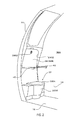
- is a perspective view illustrating the stowage position of a
diaper changing platform 36 of theaircraft lavatory unit 12A according to the first embodiment. - FIG. 3
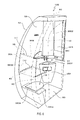
- is a perspective view illustrating the usage position of the
diaper changing platform 36 of theaircraft lavatory unit 12A according to the first embodiment. - FIGS. 4A and 4B
- are perspective views illustrating a configuration of an
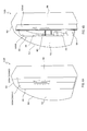
aircraft lavatory unit 12B according to a second embodiment.FIG. 4A illustrates the position when adoor 3004 is closed, andFIG. 4B illustrates the position when thedoor 3004 is opened. - FIG. 5
- is a plan view illustrating the configuration of the
aircraft lavatory unit 12B according to the second embodiment. - FIG. 6
- is a perspective view illustrating the stowage position and usage position of the
diaper changing platform 36 of theaircraft lavatory unit 12B according to the second embodiment. - The following is a description of an
aircraft lavatory unit 12A (hereinafter, referred to as thelavatory unit 12A) according to a first embodiment with reference toFIGS. 1 to 3 .
As illustrated inFIG. 1 , astructural frame 14 of thelavatory unit 12A includes abottom wall 16, afirst side wall 18, asecond side wall 20, athird side wall 22, arear surface wall 24, afront surface wall 26, and a ceiling wall which is not illustrated on the drawings.
Thebottom wall 16 includes a rectangular narrow width part and a broad width part, and thebottom wall 16 constitutes the floor of thelavatory unit 12A.
Thefirst side wall 18 rises from a first long side of the narrow width part and a first end portion of the broad width part, thesecond side wall 20 rises from a second long side of the narrow width part, and thethird side wall 22 rises from a second end portion of the broad width part.
Therear surface wall 24 rises from a short side of the narrow width part and is connected to the end portions of thefirst side wall 18 and thesecond side wall 20. Therear surface wall 24 is formed into a shape that includes a curved surface corresponding to (overlapping with) the side wall of the fuselage, because thelavatory unit 12A is disposed near a side wall within the aircraft. Thefront surface wall 26 rises from an end portion of the broad width part opposite therear surface wall 24 and is connected to thefirst side wall 18 and thethird side wall 22. Adoorway 30 is provided in thefront surface wall 26. Thedoorway 30 comprises an opening 3002 provided in thefront surface wall 26, and adoor 3004 that opens and closes off the opening 3002.
Also, alavatory chamber 38A is formed by arranging atoilet bowl 32, awash hand basin 34, and adiaper changing platform 36 within thestructural frame 14. - The
wash hand basin 34 is arranged in a location of thelavatory chamber 38A inside of thethird side wall 22.
Thetoilet bowl 32 is arranged at the end of thelavatory chamber 38A on therear surface wall 24 side, thefirst side wall 18 and thesecond side wall 20 are located on both sides of thetoilet bowl 32, and therear surface wall 24 is located to the rear of thetoilet bowl 32. Therefore, in this embodiment, the wall face of thefirst side wall 18 and thesecond side wall 20 corresponds to the first wall face in the claims, and the wall face of therear surface wall 24 corresponds to the second wall face in the claims.
Thetoilet bowl 32 comprises atoilet seat 3202, and alid 3204 that covers thetoilet seat 3202 in a lowered position and leaves thetoilet seat 3202 open in a raised position. - As illustrated in
FIGS. 1 and2 ,handrails 40 are provided on the opposingfirst side wall 18 and thesecond side wall 20 which sandwich thetoilet bowl 32, the handrails for use when sitting down on thetoilet seat 3202 or when standing up from thetoilet seat 3202.
Thehandrails 40 have an elongated shape extending substantially parallel to the floor.
Thehandrails 40 are formed integrally with thefirst side wall 18 and thesecond side wall 20.
Any of the conventionally known various shapes such as a rectangular or circular cross-section or the like can be used for the shape of thehandrails 40 provided it is a shape that a hand can grip. - As illustrated in
FIGS. 2 and3 , thediaper changing platform 36 has a substantially rectangular plate shape.
Thediaper changing platform 36 is configured from, for example, a frame that is light and stiff made from a material such as a honeycomb sandwich panel, a synthetic resin, or the like, to which a cushioning material is applied. The position that the cushioning material is applied to is thetop surface 36A on which a baby is laid down when changing its diaper. Note that the configuration of thediaper changing platform 36 can be any of the various commonly known structures. - The
diaper changing platform 36 is attached at one side portion thereof to a position on therear surface wall 24 located above thetoilet bowl 32 via a hinge that is not illustrated on the drawings, and provided so that thediaper changing platform 36 can be pivoted between a stowage position in which thediaper changing platform 36 is stowed with thetop surface 36A in a stowage recess 2402 in therear surface wall 24 with the hinge as a support point, as illustrated inFIG. 2 , and a usage position in which thediaper changing platform 36 is lowered above thetoilet bowl 32 with thetop surface 36A facing up, as illustrated inFIG. 3 .
In this embodiment, in the stowage position of thediaper changing platform 36, thebottom surface 36B of thediaper changing platform 36 and the wall face of therear surface wall 24 are configured as being continuous.
Also, ahandle 3602 for disengaging actions and a fastener (not illustrated on the drawings) for disengaging from a catching part provided on therear surface wall 24 using the action of thehandle 3602 when thediaper changing platform 36 is in the stowage position are provided in a position on thebottom surface 36B of thediaper changing platform 36 on the opposite side to the hinge, as illustrated inFIG. 2 . Thediaper changing platform 36 is retained in the stowage position by engaging the fastener with the catching part with the action of thehandle 3602, and when the engagement of the catching part with the fastener is released, thediaper changing platform 36 can be pivoted from the stowage position to the usage position. - The
diaper changing platform 36 is configured so that in the usage position, thediaper changing platform 36 is supported by placing the side portion on thefirst side wall 18 side and the side portion on thesecond side wall 20 side of thebottom surface 36B on thehandrails 40 of thefirst side wall 18 and thesecond side wall 20, and thediaper changing platform 36 is retained in the usage position.
In this embodiment, thediaper changing platform 36 is configured so that the entire length in the longitudinal direction of the top surface of thehandrails 40 contacts the side portions of thebottom surface 36B of thediaper changing platform 36, and thediaper changing platform 36 can be retained more stably in the usage position. - According to this embodiment, both side portions of the
bottom surface 36B of thediaper changing platform 36 are supported by thehandrails 40 in the usage position, so it is not necessary that the structure of the hinge of thediaper changing platform 36 be strong, which has the advantage that it is possible to reduce the size and weight of thelavatory unit 12A.
Also, thediaper changing platform 36 in the usage position is retained by thehandrails 40 that are used when sitting down onto thetoilet seat 3202 or standing up from thetoilet seat 3202, so when thediaper changing platform 36 is not being used, special members for supporting thediaper changing platform 36 do not project into thelavatory chamber 38A, which has the advantage that the usability of thenarrow lavatory chamber 38A is increased.
Also, the entire length in the longitudinal direction of thehandrails 40 contacts the side portions of thebottom surface 36B of thediaper changing platform 36, which has the advantage that thediaper changing platform 36 is stably supported in the usage position. - Next, an
aircraft lavatory unit 12B (hereinafter, referred to as thelavatory unit 12B) according to a second embodiment is described with reference toFIGS. 4 to 6 . In the description of the embodiment below, positions that are the same as or similar to those of the first embodiment are given the same reference numerals, and their description is omitted.
In the second embodiment, the structure of thestructural frame 14 of thelavatory unit 12B differs from that of the first embodiment.
In other words, abottom wall 50 does not include the narrow width part and the broad width part of the first embodiment, but has a rectangular shape as illustrated inFIGS. 5 and6 .
Thebottom wall 50 constitutes the floor of thelavatory unit 12B, afront surface wall 52 and arear surface wall 54 rise from the long sides of thebottom wall 50, afirst side wall 56 rises from a first short side of thebottom wall 50, asecond side wall 58 rises from a second short side of thebottom wall 50, and aceiling wall 60 is connected to the top portions of thefront surface wall 52, therear surface wall 54, thefirst side wall 56, and thesecond side wall 58.
Thefirst side wall 56 is formed into a shape that includes a curved surface corresponding to (overlapping with) the side wall of the fuselage, because thelavatory unit 12B is disposed near a side wall within the aircraft.
As illustrated inFIGS. 4A and 4B , thedoorway 30 is provided in thefront surface wall 52 at the end toward thesecond side wall 58. Thedoorway 30 comprises anopening 3002 provided in thefront surface wall 52, and adoor 3004 that opens and closes off theopening 3002. Thedoor 3004 is a double-folded door including twodoor members opening 3002 by folding the outer surfaces of the two door members to the outside of thelavatory unit 12B in a V-shape.
Also, thetoilet bowl 32, thewash hand basin 34, adust box 35A, amirror 35B, astowage cabinet 35C, and thediaper changing platform 36 are disposed within thestructural frame 14 to form alavatory chamber 38B. - The
wash hand basin 34 is disposed in the corner between therear surface wall 54 and thesecond side wall 58 opposite thedoorway 30, thedust box 35A is provided below thewash hand basin 34, thestowage cabinet 35C is provided above thewash hand basin 34, andreference numeral 3502 inFIGS. 5 and6 indicates a trash feeding port of thedust box 35A. - The
toilet bowl 32 is arranged at the end of thelavatory chamber 38B on thefirst side wall 56 side (the end of thebottom wall 50 toward the first side wall 56), thefront surface wall 52 and therear surface wall 54 are located on both sides of thetoilet bowl 32, and thefirst side wall 56 is located to the rear of thetoilet bowl 32. Therefore, in this embodiment, the wall face of thefront surface wall 52 and therear surface wall 54 corresponds to the first wall face in the claims, and the wall face of thefirst side wall 56 corresponds to the second wall face in the claims.
Thetoilet bowl 32 comprises atoilet seat 3202, and alid 3204 that covers thetoilet seat 3202 in a lowered position and leaves thetoilet seat 3202 open in a raised position. - As illustrated in
FIGS. 5 and6 ,handrails 40 are provided on the opposingfront surface wall 52 and therear surface wall 54 which sandwich thetoilet bowl 32, the handrails for use when sitting down on thetoilet seat 3202 or when standing up from thetoilet seat 3202, and the configuration of thehandrails 40 is the same as that of the first embodiment.. - As indicated by the imaginary lines in
FIG. 6 , thediaper changing platform 36 has a substantially rectangular plate-like shape, and the configuration of thediaper changing platform 36 is the same as that of the first embodiment.
Thediaper changing platform 36 is attached at one side portion thereof to a position on thefirst side wall 56 located above thetoilet bowl 32 via a hinge that is not illustrated on the drawings, the same as in the first embodiment, and provided so that thediaper changing platform 36 can be pivoted between a stowage position in which thediaper changing platform 36 is stowed with thetop surface 36A in astowage recess 5602 in thefirst side wall 56 with the hinge as a support point, as indicated by the symbol (a) inFIG. 6 , and a usage position in which thediaper changing platform 36 is lowered above thetoilet bowl 32 with thetop surface 36A facing up, as indicated by the symbol (b) inFIG. 6 .
In this embodiment, in the stowage position of thediaper changing platform 36, thebottom surface 36B of thediaper changing platform 36 and the wall face of thefirst side wall 56 are configured as being continuous.
Also, a handle 3602 (seeFIG. 2 ) for disengaging actions and a fastener for disengaging from a catching part provided on thefirst side wall 56 using the action of thehandle 3602 when thediaper changing platform 36 is in the stowage position are provided in a position on thebottom surface 36B of thediaper changing platform 36 on the opposite side to the hinge, as with the first embodiment. Thediaper changing platform 36 is retained in the stowage position by engaging the fastener with the catching part with the action of thehandle 3602, and when the engagement of the catching part with the fastener is released, thediaper changing platform 36 can be pivoted from the stowage position to the usage position. - The
diaper changing platform 36 is configured so that in the usage position, thediaper changing platform 36 is supported by placing the side portion on thefront surface wall 52 side and the side portion on therear surface wall 54 side of thebottom surface 36B on thehandrails 40 of thefront surface wall 52 and therear surface wall 54, and thediaper changing platform 36 is retained in the usage position.
In the second embodiment, thediaper changing platform 36 is configured so that the entire length in the longitudinal direction of thehandrails 40 contacts the side portions of thebottom surface 36B of thediaper changing platform 36, and thediaper changing platform 36 can be retained more stably in the usage position, the same as in the first embodiment. - According to the second embodiment, the same effect as the first embodiment is exhibited.
In other words, both side portions of thebottom surface 36B of thediaper changing platform 36 are supported by thehandrails 40 in the usage position, so it is not necessary that the structure of the hinge of thediaper changing platform 36 be strong, which has the advantage that it is possible to reduce the size and weight of thelavatory unit 12B.
Also, when thediaper changing platform 36 is not being used, special members for supporting thediaper changing platform 36 do not project into thelavatory chamber 38B, which has the advantage that the usability of thenarrow lavatory chamber 38B is increased.
In particular, as in the second embodiment, because thelavatory unit 12B is arranged within limited space within an aircraft, the floor of thelavatory unit 12B has a rectangular shape, so it is extremely advantageous when thediaper changing platform 36 is provided in thenarrow lavatory chamber 38B so that it can be pivoted without making the space within thelavatory chamber 38B narrower.
Also, the entire length in the longitudinal direction of thehandrails 40 contacts the side portions of thebottom surface 36B of thediaper changing platform 36, which has the advantage that thediaper changing platform 36 is stably supported in the usage position. -
- 12A, 12B
- Aircraft lavatory unit
- 18
- First side wall
- 20
- Second side wall
- 24
- Rear surface wall
- 32
- Toilet bowl
- 36
- Diaper changing platform
- 38A, 38B
- Lavatory chamber
- 40
- Handrail
- 52
- Front surface wall
- 54
- Rear surface wall
- 56
- First side wall
Claims (3)
- An aircraft lavatory unit having a toilet bowl provided within a structural frame,
the structural frame including two first wall faces disposed opposite each other, and a second wall face that connects the first wall faces,
the toilet bowl being disposed so that the two first wall faces are located at both sides of the toilet bowl, and the second wall face being located to the rear of the toilet bowl,
handrails being provided at positions on the two first wall faces sandwiching the toilet bowl, the handrails for use when sitting down onto a toilet seat of the toilet bowl and when standing up from the toilet seat,
a diaper changing platform being provided on the second wall face with a position above the toilet bowl as a support point, that is capable of being pivoted between a stowage position conforming to the second wall face and a usage position when it is lowered to above the toilet bowl, and
in the usage position, the diaper changing platform being supported at side portions of the diaper changing platform on the two first wall face sides, by the handrails of the two first wall faces. - The aircraft lavatory unit according to claim 1, wherein
the structural frame includes a floor,
the handrails have an elongated shape and extend parallel to the floor, and
the support of the side portions by the handrails in the usage position is through contact of the entire length in the longitudinal direction of the handrails with the bottom surface of the side portions of the diaper changing platform. - The aircraft lavatory unit according to claim 1 or 2, wherein
the structural frame includes a rectangular shaped floor, a front surface wall that rises from a first long side of two long sides of the floor, a rear surface wall that rises from a second long side of the two long sides, a first side wall that rises from a first short side of the two short sides of the floor, and a second side wall that rises from a second short side of the two short sides,
the toilet bowl is disposed at an end portion of the floor near the first side wall,
a doorway is provided in the front surface wall at an end portion near the second side wall,
the two first wall faces are the wall faces of the front surface wall and the rear surface wall, and
the second wall face is the wall face of the first side wall.
Applications Claiming Priority (1)
| Application Number | Priority Date | Filing Date | Title |
|---|---|---|---|
| PCT/JP2012/005498 WO2014033786A1 (en) | 2012-08-30 | 2012-08-30 | Aircraft lavatory unit |
Publications (3)
| Publication Number | Publication Date |
|---|---|
| EP2891607A1 true EP2891607A1 (en) | 2015-07-08 |
| EP2891607A4 EP2891607A4 (en) | 2016-04-13 |
| EP2891607B1 EP2891607B1 (en) | 2018-04-18 |
Family
ID=50182638
Family Applications (1)
| Application Number | Title | Priority Date | Filing Date |
|---|---|---|---|
| EP12883598.0A Not-in-force EP2891607B1 (en) | 2012-08-30 | 2012-08-30 | Aircraft lavatory unit |
Country Status (4)
| Country | Link |
|---|---|
| US (1) | US9868529B2 (en) |
| EP (1) | EP2891607B1 (en) |
| JP (1) | JP6127515B2 (en) |
| WO (1) | WO2014033786A1 (en) |
Families Citing this family (5)
| Publication number | Priority date | Publication date | Assignee | Title |
|---|---|---|---|---|
| JP6134683B2 (en) * | 2014-03-31 | 2017-05-24 | 株式会社ジャムコ | Aircraft lavatory unit |
| US11939062B2 (en) * | 2020-03-27 | 2024-03-26 | Jamco Corporation | Aircraft lavatory unit |
| US11262646B2 (en) | 2020-05-14 | 2022-03-01 | The Boeing Company | Projection system for baby-changing station translucent displays and methods of operating thereof |
| US11178365B1 (en) | 2020-05-14 | 2021-11-16 | The Boeing Company | Projection system for translucent displays and methods of operating thereof |
| DE102024121969A1 (en) * | 2024-08-01 | 2026-02-05 | Airbus Operations Gmbh | Washroom for use by people with reduced mobility |
Family Cites Families (11)
| Publication number | Priority date | Publication date | Assignee | Title |
|---|---|---|---|---|
| JPH07116851B2 (en) | 1987-12-02 | 1995-12-18 | 東陶機器株式会社 | Water room complex |
| JPH0640399A (en) * | 1991-12-09 | 1994-02-15 | Toto Ltd | Aircraft lavatory |
| WO2004076281A1 (en) * | 2003-02-21 | 2004-09-10 | The Boeing Company | Dual purpose lavatory |
| US7222820B2 (en) * | 2003-02-25 | 2007-05-29 | The Boeing Company | Aircraft lavatory |
| JP4283042B2 (en) | 2003-06-06 | 2009-06-24 | 東日本旅客鉄道株式会社 | Railway vehicle sanitary area structure |
| DE10339077A1 (en) * | 2003-08-26 | 2005-03-31 | Airbus Deutschland Gmbh | Passenger compartment in the cabin of a commercial airplane |
| JP4983337B2 (en) | 2007-03-28 | 2012-07-25 | 横浜ゴム株式会社 | Aircraft restroom |
| JP4978272B2 (en) * | 2007-03-28 | 2012-07-18 | 横浜ゴム株式会社 | Aircraft restroom |
| JP2008239042A (en) | 2007-03-28 | 2008-10-09 | Yokohama Rubber Co Ltd:The | Restroom for aircraft |
| US9708062B2 (en) * | 2011-04-18 | 2017-07-18 | C Series Aircraft Limited Partnership | Aircraft lavatory for a person with reduced mobility |
| US8944377B2 (en) * | 2013-06-11 | 2015-02-03 | The Boeing Company | Lavatory reconfiguration system |
-
2012
- 2012-08-30 EP EP12883598.0A patent/EP2891607B1/en not_active Not-in-force
- 2012-08-30 WO PCT/JP2012/005498 patent/WO2014033786A1/en not_active Ceased
- 2012-08-30 JP JP2012551009A patent/JP6127515B2/en not_active Expired - Fee Related
- 2012-08-30 US US14/424,866 patent/US9868529B2/en not_active Expired - Fee Related
Also Published As
| Publication number | Publication date |
|---|---|
| EP2891607A4 (en) | 2016-04-13 |
| US9868529B2 (en) | 2018-01-16 |
| EP2891607B1 (en) | 2018-04-18 |
| JP6127515B2 (en) | 2017-05-17 |
| JPWO2014033786A1 (en) | 2016-08-08 |
| WO2014033786A1 (en) | 2014-03-06 |
| US20160059965A1 (en) | 2016-03-03 |
Similar Documents
| Publication | Publication Date | Title |
|---|---|---|
| EP2891607B1 (en) | Aircraft lavatory unit | |
| EP2165599B1 (en) | Animal toilet | |
| EP2907752A1 (en) | Aircraft bathroom unit | |
| CN104773115A (en) | Sliding door for a storage bin in a vehicle center floor console | |
| IL150360A (en) | Aircraft multi-function overhead space access module | |
| JP2009161086A (en) | Vehicle sliding door structure | |
| US11718383B2 (en) | Joint structure for bathroom door body of airplane bathroom unit | |
| WO2013125218A1 (en) | Installation method for airplane lavatory unit, and airplane | |
| US10889210B2 (en) | Apparatus for a vehicle and a vehicle | |
| EP2848529B1 (en) | Airplane comprising a structure arrangement with a lavatory unit | |
| JP6134683B2 (en) | Aircraft lavatory unit | |
| KR101204004B1 (en) | Door frame for improving assembliy and entering easily | |
| CN108366703B (en) | Plug-in dispenser for sheet products, cabinet for mounting a plug-in dispenser and use of a plug-in dispenser in a cabinet | |
| KR200459579Y1 (en) | device of sliding door | |
| JP2025110909A (en) | Private compartment structure that can be installed on an aircraft | |
| CA2737577A1 (en) | Aircraft lavatory for a person in a wheelchair | |
| JP2008212217A (en) | Toilet | |
| CN102920386A (en) | Portable self-carrying toilet | |
| TW201900092A (en) | toilet lid | |
| JP2006348494A (en) | Closing cover device | |
| US8276220B1 (en) | Height adjustable seat | |
| KR101071487B1 (en) | System toilet having a box of saving space type | |
| JP3113869U (en) | Western style urinal screen | |
| CN206782585U (en) | A kind of space shuttle is for passenger's Portable rubbish holder | |
| JP5327008B2 (en) | Face-to-face kitchen counter |
Legal Events
| Date | Code | Title | Description |
|---|---|---|---|
| PUAI | Public reference made under article 153(3) epc to a published international application that has entered the european phase |
Free format text: ORIGINAL CODE: 0009012 |
|
| 17P | Request for examination filed |
Effective date: 20150227 |
|
| AK | Designated contracting states |
Kind code of ref document: A1 Designated state(s): AL AT BE BG CH CY CZ DE DK EE ES FI FR GB GR HR HU IE IS IT LI LT LU LV MC MK MT NL NO PL PT RO RS SE SI SK SM TR |
|
| AX | Request for extension of the european patent |
Extension state: BA ME |
|
| DAX | Request for extension of the european patent (deleted) | ||
| RA4 | Supplementary search report drawn up and despatched (corrected) |
Effective date: 20160314 |
|
| RIC1 | Information provided on ipc code assigned before grant |
Ipc: B64D 11/02 20060101AFI20160308BHEP Ipc: A47K 17/02 20060101ALI20160308BHEP |
|
| RIN1 | Information on inventor provided before grant (corrected) |
Inventor name: KOYAMA, TAKASHI Inventor name: FUSHIMI, MASAYUKI |
|
| GRAP | Despatch of communication of intention to grant a patent |
Free format text: ORIGINAL CODE: EPIDOSNIGR1 |
|
| STAA | Information on the status of an ep patent application or granted ep patent |
Free format text: STATUS: GRANT OF PATENT IS INTENDED |
|
| INTG | Intention to grant announced |
Effective date: 20171124 |
|
| GRAS | Grant fee paid |
Free format text: ORIGINAL CODE: EPIDOSNIGR3 |
|
| GRAA | (expected) grant |
Free format text: ORIGINAL CODE: 0009210 |
|
| STAA | Information on the status of an ep patent application or granted ep patent |
Free format text: STATUS: THE PATENT HAS BEEN GRANTED |
|
| AK | Designated contracting states |
Kind code of ref document: B1 Designated state(s): AL AT BE BG CH CY CZ DE DK EE ES FI FR GB GR HR HU IE IS IT LI LT LU LV MC MK MT NL NO PL PT RO RS SE SI SK SM TR |
|
| REG | Reference to a national code |
Ref country code: GB Ref legal event code: FG4D |
|
| REG | Reference to a national code |
Ref country code: CH Ref legal event code: EP |
|
| REG | Reference to a national code |
Ref country code: AT Ref legal event code: REF Ref document number: 990166 Country of ref document: AT Kind code of ref document: T Effective date: 20180515 |
|
| REG | Reference to a national code |
Ref country code: IE Ref legal event code: FG4D |
|
| REG | Reference to a national code |
Ref country code: DE Ref legal event code: R096 Ref document number: 602012045484 Country of ref document: DE |
|
| REG | Reference to a national code |
Ref country code: NL Ref legal event code: MP Effective date: 20180418 |
|
| REG | Reference to a national code |
Ref country code: LT Ref legal event code: MG4D |
|
| PG25 | Lapsed in a contracting state [announced via postgrant information from national office to epo] |
Ref country code: NL Free format text: LAPSE BECAUSE OF FAILURE TO SUBMIT A TRANSLATION OF THE DESCRIPTION OR TO PAY THE FEE WITHIN THE PRESCRIBED TIME-LIMIT Effective date: 20180418 |
|
| PG25 | Lapsed in a contracting state [announced via postgrant information from national office to epo] |
Ref country code: NO Free format text: LAPSE BECAUSE OF FAILURE TO SUBMIT A TRANSLATION OF THE DESCRIPTION OR TO PAY THE FEE WITHIN THE PRESCRIBED TIME-LIMIT Effective date: 20180718 Ref country code: SE Free format text: LAPSE BECAUSE OF FAILURE TO SUBMIT A TRANSLATION OF THE DESCRIPTION OR TO PAY THE FEE WITHIN THE PRESCRIBED TIME-LIMIT Effective date: 20180418 Ref country code: BG Free format text: LAPSE BECAUSE OF FAILURE TO SUBMIT A TRANSLATION OF THE DESCRIPTION OR TO PAY THE FEE WITHIN THE PRESCRIBED TIME-LIMIT Effective date: 20180718 Ref country code: FI Free format text: LAPSE BECAUSE OF FAILURE TO SUBMIT A TRANSLATION OF THE DESCRIPTION OR TO PAY THE FEE WITHIN THE PRESCRIBED TIME-LIMIT Effective date: 20180418 Ref country code: AL Free format text: LAPSE BECAUSE OF FAILURE TO SUBMIT A TRANSLATION OF THE DESCRIPTION OR TO PAY THE FEE WITHIN THE PRESCRIBED TIME-LIMIT Effective date: 20180418 Ref country code: PL Free format text: LAPSE BECAUSE OF FAILURE TO SUBMIT A TRANSLATION OF THE DESCRIPTION OR TO PAY THE FEE WITHIN THE PRESCRIBED TIME-LIMIT Effective date: 20180418 Ref country code: LT Free format text: LAPSE BECAUSE OF FAILURE TO SUBMIT A TRANSLATION OF THE DESCRIPTION OR TO PAY THE FEE WITHIN THE PRESCRIBED TIME-LIMIT Effective date: 20180418 Ref country code: ES Free format text: LAPSE BECAUSE OF FAILURE TO SUBMIT A TRANSLATION OF THE DESCRIPTION OR TO PAY THE FEE WITHIN THE PRESCRIBED TIME-LIMIT Effective date: 20180418 |
|
| PG25 | Lapsed in a contracting state [announced via postgrant information from national office to epo] |
Ref country code: LV Free format text: LAPSE BECAUSE OF FAILURE TO SUBMIT A TRANSLATION OF THE DESCRIPTION OR TO PAY THE FEE WITHIN THE PRESCRIBED TIME-LIMIT Effective date: 20180418 Ref country code: HR Free format text: LAPSE BECAUSE OF FAILURE TO SUBMIT A TRANSLATION OF THE DESCRIPTION OR TO PAY THE FEE WITHIN THE PRESCRIBED TIME-LIMIT Effective date: 20180418 Ref country code: GR Free format text: LAPSE BECAUSE OF FAILURE TO SUBMIT A TRANSLATION OF THE DESCRIPTION OR TO PAY THE FEE WITHIN THE PRESCRIBED TIME-LIMIT Effective date: 20180719 Ref country code: RS Free format text: LAPSE BECAUSE OF FAILURE TO SUBMIT A TRANSLATION OF THE DESCRIPTION OR TO PAY THE FEE WITHIN THE PRESCRIBED TIME-LIMIT Effective date: 20180418 |
|
| REG | Reference to a national code |
Ref country code: AT Ref legal event code: MK05 Ref document number: 990166 Country of ref document: AT Kind code of ref document: T Effective date: 20180418 |
|
| PG25 | Lapsed in a contracting state [announced via postgrant information from national office to epo] |
Ref country code: PT Free format text: LAPSE BECAUSE OF FAILURE TO SUBMIT A TRANSLATION OF THE DESCRIPTION OR TO PAY THE FEE WITHIN THE PRESCRIBED TIME-LIMIT Effective date: 20180820 |
|
| REG | Reference to a national code |
Ref country code: DE Ref legal event code: R097 Ref document number: 602012045484 Country of ref document: DE |
|
| PG25 | Lapsed in a contracting state [announced via postgrant information from national office to epo] |
Ref country code: DK Free format text: LAPSE BECAUSE OF FAILURE TO SUBMIT A TRANSLATION OF THE DESCRIPTION OR TO PAY THE FEE WITHIN THE PRESCRIBED TIME-LIMIT Effective date: 20180418 Ref country code: AT Free format text: LAPSE BECAUSE OF FAILURE TO SUBMIT A TRANSLATION OF THE DESCRIPTION OR TO PAY THE FEE WITHIN THE PRESCRIBED TIME-LIMIT Effective date: 20180418 Ref country code: EE Free format text: LAPSE BECAUSE OF FAILURE TO SUBMIT A TRANSLATION OF THE DESCRIPTION OR TO PAY THE FEE WITHIN THE PRESCRIBED TIME-LIMIT Effective date: 20180418 Ref country code: RO Free format text: LAPSE BECAUSE OF FAILURE TO SUBMIT A TRANSLATION OF THE DESCRIPTION OR TO PAY THE FEE WITHIN THE PRESCRIBED TIME-LIMIT Effective date: 20180418 Ref country code: CZ Free format text: LAPSE BECAUSE OF FAILURE TO SUBMIT A TRANSLATION OF THE DESCRIPTION OR TO PAY THE FEE WITHIN THE PRESCRIBED TIME-LIMIT Effective date: 20180418 Ref country code: SK Free format text: LAPSE BECAUSE OF FAILURE TO SUBMIT A TRANSLATION OF THE DESCRIPTION OR TO PAY THE FEE WITHIN THE PRESCRIBED TIME-LIMIT Effective date: 20180418 |
|
| PLBE | No opposition filed within time limit |
Free format text: ORIGINAL CODE: 0009261 |
|
| STAA | Information on the status of an ep patent application or granted ep patent |
Free format text: STATUS: NO OPPOSITION FILED WITHIN TIME LIMIT |
|
| PG25 | Lapsed in a contracting state [announced via postgrant information from national office to epo] |
Ref country code: SM Free format text: LAPSE BECAUSE OF FAILURE TO SUBMIT A TRANSLATION OF THE DESCRIPTION OR TO PAY THE FEE WITHIN THE PRESCRIBED TIME-LIMIT Effective date: 20180418 Ref country code: IT Free format text: LAPSE BECAUSE OF FAILURE TO SUBMIT A TRANSLATION OF THE DESCRIPTION OR TO PAY THE FEE WITHIN THE PRESCRIBED TIME-LIMIT Effective date: 20180418 |
|
| REG | Reference to a national code |
Ref country code: DE Ref legal event code: R119 Ref document number: 602012045484 Country of ref document: DE |
|
| 26N | No opposition filed |
Effective date: 20190121 |
|
| PG25 | Lapsed in a contracting state [announced via postgrant information from national office to epo] |
Ref country code: MC Free format text: LAPSE BECAUSE OF FAILURE TO SUBMIT A TRANSLATION OF THE DESCRIPTION OR TO PAY THE FEE WITHIN THE PRESCRIBED TIME-LIMIT Effective date: 20180418 |
|
| REG | Reference to a national code |
Ref country code: CH Ref legal event code: PL |
|
| GBPC | Gb: european patent ceased through non-payment of renewal fee |
Effective date: 20180830 |
|
| PG25 | Lapsed in a contracting state [announced via postgrant information from national office to epo] |
Ref country code: CH Free format text: LAPSE BECAUSE OF NON-PAYMENT OF DUE FEES Effective date: 20180831 Ref country code: LI Free format text: LAPSE BECAUSE OF NON-PAYMENT OF DUE FEES Effective date: 20180831 Ref country code: LU Free format text: LAPSE BECAUSE OF NON-PAYMENT OF DUE FEES Effective date: 20180830 |
|
| REG | Reference to a national code |
Ref country code: BE Ref legal event code: MM Effective date: 20180831 |
|
| PG25 | Lapsed in a contracting state [announced via postgrant information from national office to epo] |
Ref country code: SI Free format text: LAPSE BECAUSE OF FAILURE TO SUBMIT A TRANSLATION OF THE DESCRIPTION OR TO PAY THE FEE WITHIN THE PRESCRIBED TIME-LIMIT Effective date: 20180418 |
|
| PG25 | Lapsed in a contracting state [announced via postgrant information from national office to epo] |
Ref country code: DE Free format text: LAPSE BECAUSE OF NON-PAYMENT OF DUE FEES Effective date: 20190301 |
|
| PG25 | Lapsed in a contracting state [announced via postgrant information from national office to epo] |
Ref country code: FR Free format text: LAPSE BECAUSE OF NON-PAYMENT OF DUE FEES Effective date: 20180831 Ref country code: BE Free format text: LAPSE BECAUSE OF NON-PAYMENT OF DUE FEES Effective date: 20180831 |
|
| PG25 | Lapsed in a contracting state [announced via postgrant information from national office to epo] |
Ref country code: GB Free format text: LAPSE BECAUSE OF NON-PAYMENT OF DUE FEES Effective date: 20180830 |
|
| PG25 | Lapsed in a contracting state [announced via postgrant information from national office to epo] |
Ref country code: MT Free format text: LAPSE BECAUSE OF NON-PAYMENT OF DUE FEES Effective date: 20180830 |
|
| PG25 | Lapsed in a contracting state [announced via postgrant information from national office to epo] |
Ref country code: TR Free format text: LAPSE BECAUSE OF FAILURE TO SUBMIT A TRANSLATION OF THE DESCRIPTION OR TO PAY THE FEE WITHIN THE PRESCRIBED TIME-LIMIT Effective date: 20180418 |
|
| PG25 | Lapsed in a contracting state [announced via postgrant information from national office to epo] |
Ref country code: CY Free format text: LAPSE BECAUSE OF FAILURE TO SUBMIT A TRANSLATION OF THE DESCRIPTION OR TO PAY THE FEE WITHIN THE PRESCRIBED TIME-LIMIT Effective date: 20180418 Ref country code: HU Free format text: LAPSE BECAUSE OF FAILURE TO SUBMIT A TRANSLATION OF THE DESCRIPTION OR TO PAY THE FEE WITHIN THE PRESCRIBED TIME-LIMIT; INVALID AB INITIO Effective date: 20120830 Ref country code: IE Free format text: LAPSE BECAUSE OF NON-PAYMENT OF DUE FEES Effective date: 20180830 Ref country code: MK Free format text: LAPSE BECAUSE OF NON-PAYMENT OF DUE FEES Effective date: 20180418 |
|
| PG25 | Lapsed in a contracting state [announced via postgrant information from national office to epo] |
Ref country code: IS Free format text: LAPSE BECAUSE OF FAILURE TO SUBMIT A TRANSLATION OF THE DESCRIPTION OR TO PAY THE FEE WITHIN THE PRESCRIBED TIME-LIMIT Effective date: 20180818 |