EP2891434A1 - Roller blind cover and connector for the roller blind cover - Google Patents
Roller blind cover and connector for the roller blind cover Download PDFInfo
- Publication number
- EP2891434A1 EP2891434A1 EP14461502.8A EP14461502A EP2891434A1 EP 2891434 A1 EP2891434 A1 EP 2891434A1 EP 14461502 A EP14461502 A EP 14461502A EP 2891434 A1 EP2891434 A1 EP 2891434A1
- Authority
- EP
- European Patent Office
- Prior art keywords
- corner
- wall part
- connector
- wall
- catch pawl
- Prior art date
- Legal status (The legal status is an assumption and is not a legal conclusion. Google has not performed a legal analysis and makes no representation as to the accuracy of the status listed.)
- Granted
Links
- 238000009434 installation Methods 0.000 claims description 12
- 230000003014 reinforcing effect Effects 0.000 claims description 7
- 238000005520 cutting process Methods 0.000 description 2
- 239000004411 aluminium Substances 0.000 description 1
- 229910052782 aluminium Inorganic materials 0.000 description 1
- XAGFODPZIPBFFR-UHFFFAOYSA-N aluminium Chemical compound [Al] XAGFODPZIPBFFR-UHFFFAOYSA-N 0.000 description 1
- 230000015572 biosynthetic process Effects 0.000 description 1
- 238000010276 construction Methods 0.000 description 1
- 230000006866 deterioration Effects 0.000 description 1
- 238000005553 drilling Methods 0.000 description 1
- 229910052751 metal Inorganic materials 0.000 description 1
- 239000002184 metal Substances 0.000 description 1
- 238000010079 rubber tapping Methods 0.000 description 1
- 238000007493 shaping process Methods 0.000 description 1
Images




Classifications
-
- E—FIXED CONSTRUCTIONS
- E06—DOORS, WINDOWS, SHUTTERS, OR ROLLER BLINDS IN GENERAL; LADDERS
- E06B—FIXED OR MOVABLE CLOSURES FOR OPENINGS IN BUILDINGS, VEHICLES, FENCES OR LIKE ENCLOSURES IN GENERAL, e.g. DOORS, WINDOWS, BLINDS, GATES
- E06B9/00—Screening or protective devices for wall or similar openings, with or without operating or securing mechanisms; Closures of similar construction
- E06B9/24—Screens or other constructions affording protection against light, especially against sunshine; Similar screens for privacy or appearance; Slat blinds
- E06B9/40—Roller blinds
- E06B9/42—Parts or details of roller blinds, e.g. suspension devices, blind boxes
- E06B9/50—Bearings specially adapted therefor
-
- A—HUMAN NECESSITIES
- A47—FURNITURE; DOMESTIC ARTICLES OR APPLIANCES; COFFEE MILLS; SPICE MILLS; SUCTION CLEANERS IN GENERAL
- A47H—FURNISHINGS FOR WINDOWS OR DOORS
- A47H1/00—Curtain suspension devices
- A47H1/10—Means for mounting curtain rods or rails
- A47H1/13—Brackets or adjustable mountings for both roller blinds and drawable curtains
-
- E—FIXED CONSTRUCTIONS
- E06—DOORS, WINDOWS, SHUTTERS, OR ROLLER BLINDS IN GENERAL; LADDERS
- E06B—FIXED OR MOVABLE CLOSURES FOR OPENINGS IN BUILDINGS, VEHICLES, FENCES OR LIKE ENCLOSURES IN GENERAL, e.g. DOORS, WINDOWS, BLINDS, GATES
- E06B9/00—Screening or protective devices for wall or similar openings, with or without operating or securing mechanisms; Closures of similar construction
- E06B9/24—Screens or other constructions affording protection against light, especially against sunshine; Similar screens for privacy or appearance; Slat blinds
- E06B9/40—Roller blinds
- E06B9/42—Parts or details of roller blinds, e.g. suspension devices, blind boxes
Definitions
- the invention relates to a roller window blind cover and to a connector for the blind cover with a design enabling repeated assembly and disassembly.
- roller window blind covers are intended for a specific blind design. It is particularly strenuous in case of roller blinds with a design enabling adjustment of the blind width to requirements resulting from the width of the object they are installed on, as either it requires creation of a whole size range of covers with various lengths, or the structures require complicated installation procedures.
- blind covers in case of a change in the cover length, it is necessary to perform complex technical operations, for instance cutting, drilling, tapping. These operations are troublesome as they are generally performed under unprofessional conditions in the place of installation of roller blinds and their covers. It leads usually to a deterioration of aesthetic qualities of such covers.
- the goal of the invention was to create a simple design of a blind cover enabling quick and simple assembly with a possibility to change the cover's length.
- the invention relates to a blind cover including a decorative strip and a connector.
- the decorative strip is constituted by a profile, preferably made of metal, the profile having decorative elements on its exterior surface and sides, and at least one pass-through duct with a rectangular cross-section on its internal surface, while the external wall of the rectangle contains a longitudinal recess forming longitudinal protrusions directed into the duct along both sides.
- the duct is located symmetrically along the strip's axis. In such a case, it is possible to use the same connectors both on the right and the left side of the cover. When the duct is located asymmetrically, it is necessary to use two analogous but different connectors: a right-sided one and a left-sided one.
- the profile has additional pass-through ducts reinforcing and bracing the profile's structure.
- the strip is divided into three sections, with two of them having equal length and constituting the sides of the cover, while one end of the cover's side is cut at an angle of 90°, and the other one - at an angle of 45°.
- the length of the third section may be chosen freely according to the needs, while before assembly, its both ends are cut at an angle of 45°.
- the connector consists of two parts, namely a wall part and a corner.
- the wall part comprises a cuboidal casing with a shape adjusted to the shape of the duct of the decorative strip's profile, i.e. two grooves run along the whole casing wall part, the grooves having the longitudinal protrusions of the duct of the decorative strip's profile inserted into. From the external side, there is a furrow along the wall part, having a catch pawl of the corner inserted into during the assembly. In the furrow, there is a system of lateral grooves, for engaging the connector's tip of the corner. In the wall part's casing, there is an opening for unlocking of the connection of the corner's catch pawl. On the casing, from the internal side, there are elements enabling connection with the roller blind.
- the casing of the wall part has wall installation elements for installation of the cover on a wall.
- the corner consists of two rectangular prisms situated perpendicularly to one another, with shapes adjusted to the cross-section of the decorative strip's profile, while from one of the rectangular prisms, a catch pawl with a catch pawl's tip protrudes.
- the catch pawl width is no longer than the width of the wall part duct corresponding to it, and its length is such that the catch pawl's tip fits into the opening on the wall part and locks the connection of both parts after connection of the corner part with the wall part.
- the length of the catch pawl is of high importance for maintaining proper flexibility, which in turn influences the quality of the connection of both parts during and after assembly.
- the cuboidal parts of the corner part may comprise additional reinforcing ribs, performing an auxiliary function of formation of ducts, through which, for instance, low-voltage cables for LED lighting may be fed.
- the assembly of the blind cover according to the invention consists in the following sequence of operations:
- the invention relates to a connector for wall and frontal elements of blind covers.
- the connector according to the invention consists of two parts, namely a wall part and a corner.
- the wall part comprises a cuboidal casing, having two longitudinal grooves on both sides, the grooves having the longitudinal protrusions of the duct of the decorative strip's profile inserted into. From the external side, there is a furrow along the wall part, having a catch pawl of the corner inserted into during assembly. In the furrow, there is a system of lateral grooves, for engaging the connector's tip of the corner. In the wall part's casing, there is an opening for unlocking of the connection of the corner's catch pawl. On the casing, from the internal side, there are elements enabling connection with the roller blind.
- the casing of the wall part has wall installation elements for installation of the cover on a wall.
- the corner consists of two rectangular prisms situated perpendicularly to one another, with shapes adjusted to the cross-section of the decorative strip's profile, while from one of the rectangular prisms, a catch pawl with a catch pawl's tip protrudes.
- the catch pawl width is no longer than the width of the wall part duct corresponding to it, and its length is such as to the catch pawl's tip fits into the opening on the wall part and locks the connection of both parts after connection of the corner with the wall part.
- the length of the catch pawl is of high importance for maintaining proper flexibility, which in turn influences the quality of the connection of both parts during and after assembly.
- the cuboidal parts of the corner part may comprise additional reinforcing ribs.
- a blind cover is shown, the cover including a front cover (1), side covers (2, 2'), and connectors (3, 3').
- the connectors (3,3') consists of a wall part (4) and a corner (5).
- the front cover (1) and the side covers (2, 2') are made of an aluminium profile, having a centrally located duct (6) and two side ducts (7, 7') on its internal side.
- the front cover (1) has both ends cut at an angle of 45° so that the internal length of the front cover (1) is shorter.
- the side covers (2, 2') are cut on one end at an angle of 45° so that their internal length is shorter.
- the wall part (4) of the connector (3) is slid into the duct (6) of the front cover (1), and the corner (5) is slid into the duct (6) of the side cover (2).
- the wall part (4) of the connector is composed of a casing (8), a wall installation element (9), and an element for connection with the blind (10).
- the wall installation element (9) has properly formed sockets (13, 13') for heads of bolts or screws and recesses (14, 14') for bolts or screws.
- Such a shaping of the recesses (14, 14') allows a free assembly of the wall part (4) onto a wall without a necessity for precise preparation of fixing elements in the wall, such as expansion plugs.
- the element for connection with the blind (10) has an opening (15) for elements connecting the wall part (4) with the roller blind.
- the casing (8) has a recess (16) from its internal side.
- the internal structure of the wall part (4) is shown in Figure 3 .
- the recess (16) runs through the whole length and it is terminated in a plate with a recess (17) from the wall side. Through the recess, for instance electrical cables for LED lighting installed from the internal side of the cover may be fed.
- There is an opening (18) in the casing located on the axis of the opening (15) in the element for connection of the cover with the blind (10).
- On the internal surface of the casing (8) there is a system of offsets (19), with fronts facing the wall. The offsets are intended for connection with the corner (5) of the connector.
- Figure 4 a magnification of detail A from Figure 3 is shown.
- the corner (5) of the connector (3) shown in Figures 5, 6 and 7 in three views, consists of two parts (20, 21) perpendicular to one another, and both these parts have an external outline corresponding to the shape of the central duct (6) of the front cover (1) and side covers (2, 2').
- the corner (5) has ribs (22, 22', 23, 23', 24, 24') reinforcing its structure, and moreover it has an additional rib (25) reinforcing the connection of both parts of the corner (5).
- Part (21) has a catch pawl (26) intended for connection of the corner with the wall part (4) of the connector (3).
- the catch pawl (26) In its terminal part, the catch pawl (26) has a tip (27) in the form of a half of an arrow with a cant from the external side of the corner (5), and from its internal side, a protrusion (28) is formed, intended for engaging the offsets (19) of the wall part (4).
- a protrusion (28) At the both sides of the catch pawl (26), there are furrows (29, 29') elongating the catch pawl (26), therefore it is more flexible, what favourably influences its operating qualities.
- a connector (3) is shown in a position before connection in a view without the front cover.
- the catch pawl (26) of the corner is slid into the furrow (16) in the wall part (4), and next, as it is shown in Figure 10 , the tip (27) of the catch pawl (26) slides onto the system of offsets (19) of the wall part (4); then, after pushing to its terminal position, the protrusion (28) on the tip (27) locks itself on one of the offsets (19).
- FIGS 13 and 14 a sequence of steps of introduction of the wall part (4) to the duct (16') in the side cover's profile (2) is shown.
- the wall part is introduced into the side cover (2) from the side of the perpendicular cant.
- FIGs 15, 16 and 17 a sequence of steps for connection of the individual parts of the blind cover is shown, while, for the sake of clarity, the fact that the side cover (2) is fixed via the wall part (4) to the wall has been omitted.
- the front part (1) with the corner (5) is positioned perpendicularly to the side cover (2) with the catch pawl (26) oriented towards the side cover (2).
- the free end (21) of the corner (5) is slid into the duct (6') of the side cover (2) pushing home, and in this position, the protrusion (28) on the tip (27) engages the offsets (19) in the wall part (4).
- the assembly of the blind cover is finished, being shown in Figure 17 .
- FIG 18 an example of utilisation of the duct (6, 6'), the furrow (16) in the wall part (4), and the ducts in the corner (5) for feeding a low-voltage cable for LED lighting is shown.
Landscapes
- Engineering & Computer Science (AREA)
- Structural Engineering (AREA)
- Architecture (AREA)
- Civil Engineering (AREA)
- Operating, Guiding And Securing Of Roll- Type Closing Members (AREA)
- Blinds (AREA)
- Clamps And Clips (AREA)
- Curtains And Furnishings For Windows Or Doors (AREA)
- Forms Removed On Construction Sites Or Auxiliary Members Thereof (AREA)
- Floor Finish (AREA)
- Details Or Accessories Of Spraying Plant Or Apparatus (AREA)
- Finishing Walls (AREA)
- Details Of Indoor Wiring (AREA)
Abstract
Description
- The invention relates to a roller window blind cover and to a connector for the blind cover with a design enabling repeated assembly and disassembly.
- Known roller window blind covers are intended for a specific blind design. It is particularly strenuous in case of roller blinds with a design enabling adjustment of the blind width to requirements resulting from the width of the object they are installed on, as either it requires creation of a whole size range of covers with various lengths, or the structures require complicated installation procedures.
- In known designs of blind covers, in case of a change in the cover length, it is necessary to perform complex technical operations, for instance cutting, drilling, tapping. These operations are troublesome as they are generally performed under unprofessional conditions in the place of installation of roller blinds and their covers. It leads usually to a deterioration of aesthetic qualities of such covers.
- The goal of the invention was to create a simple design of a blind cover enabling quick and simple assembly with a possibility to change the cover's length.
- The invention relates to a blind cover including a decorative strip and a connector. The decorative strip is constituted by a profile, preferably made of metal, the profile having decorative elements on its exterior surface and sides, and at least one pass-through duct with a rectangular cross-section on its internal surface, while the external wall of the rectangle contains a longitudinal recess forming longitudinal protrusions directed into the duct along both sides. In a preferred version of the invention, the duct is located symmetrically along the strip's axis. In such a case, it is possible to use the same connectors both on the right and the left side of the cover. When the duct is located asymmetrically, it is necessary to use two analogous but different connectors: a right-sided one and a left-sided one.
- In a preferred version, the profile has additional pass-through ducts reinforcing and bracing the profile's structure. The strip is divided into three sections, with two of them having equal length and constituting the sides of the cover, while one end of the cover's side is cut at an angle of 90°, and the other one - at an angle of 45°. The length of the third section may be chosen freely according to the needs, while before assembly, its both ends are cut at an angle of 45°.
- The connector consists of two parts, namely a wall part and a corner.
- The wall part comprises a cuboidal casing with a shape adjusted to the shape of the duct of the decorative strip's profile, i.e. two grooves run along the whole casing wall part, the grooves having the longitudinal protrusions of the duct of the decorative strip's profile inserted into. From the external side, there is a furrow along the wall part, having a catch pawl of the corner inserted into during the assembly. In the furrow, there is a system of lateral grooves, for engaging the connector's tip of the corner. In the wall part's casing, there is an opening for unlocking of the connection of the corner's catch pawl. On the casing, from the internal side, there are elements enabling connection with the roller blind. The casing of the wall part has wall installation elements for installation of the cover on a wall.
- The corner consists of two rectangular prisms situated perpendicularly to one another, with shapes adjusted to the cross-section of the decorative strip's profile, while from one of the rectangular prisms, a catch pawl with a catch pawl's tip protrudes. The catch pawl width is no longer than the width of the wall part duct corresponding to it, and its length is such that the catch pawl's tip fits into the opening on the wall part and locks the connection of both parts after connection of the corner part with the wall part. The length of the catch pawl is of high importance for maintaining proper flexibility, which in turn influences the quality of the connection of both parts during and after assembly. To this end, in a preferred version, in order to lengthen the catch pawl at its base in the cuboidal part, there are additional furrows at both sides of the catch pawl, making the catch pawl longer than it would result from the nominal distance between its end and the end of the cuboidal part.
- The cuboidal parts of the corner part may comprise additional reinforcing ribs, performing an auxiliary function of formation of ducts, through which, for instance, low-voltage cables for LED lighting may be fed.
- The assembly of the blind cover according to the invention consists in the following sequence of operations:
- selecting a proper finished section of the frontal part of the blind cover or cutting a decorative strip to a proper length, installation of wall parts on a wall,
- sliding of side decorative strips onto the wall parts,
- sliding of the corner parts into the internal duct of the frontal part of the decorative strip,
- sliding of other ends of the corner parts into the duct formed between the wall parts and the side decorative strips and locking by sliding of the catch pawl tips into the openings in the wall parts.
- In the second aspect, the invention relates to a connector for wall and frontal elements of blind covers.
- The connector according to the invention consists of two parts, namely a wall part and a corner.
- The wall part comprises a cuboidal casing, having two longitudinal grooves on both sides, the grooves having the longitudinal protrusions of the duct of the decorative strip's profile inserted into. From the external side, there is a furrow along the wall part, having a catch pawl of the corner inserted into during assembly. In the furrow, there is a system of lateral grooves, for engaging the connector's tip of the corner. In the wall part's casing, there is an opening for unlocking of the connection of the corner's catch pawl. On the casing, from the internal side, there are elements enabling connection with the roller blind. The casing of the wall part has wall installation elements for installation of the cover on a wall.
- The corner consists of two rectangular prisms situated perpendicularly to one another, with shapes adjusted to the cross-section of the decorative strip's profile, while from one of the rectangular prisms, a catch pawl with a catch pawl's tip protrudes. The catch pawl width is no longer than the width of the wall part duct corresponding to it, and its length is such as to the catch pawl's tip fits into the opening on the wall part and locks the connection of both parts after connection of the corner with the wall part. The length of the catch pawl is of high importance for maintaining proper flexibility, which in turn influences the quality of the connection of both parts during and after assembly. To this end, in a preferred version, in order to lengthen the catch pawl at its base in the cuboidal part, there are additional furrows at both sides of the catch pawl, making the catch pawl longer than it would result from the nominal distance between its end and the end of the cuboidal part. The cuboidal parts of the corner part may comprise additional reinforcing ribs.
- The subject of the invention is presented by the way of embodiments that illustrate but do not limit the scope of the invention.
- In the drawings, the individual Figures show:
-
Figure 1 - a general view of the blind cover, -
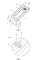
Figures 2 and3 - structural details of the wall part, -
Figure 4 - a magnification of detail "A" fromFigure 3 , -
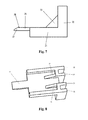
Figures 5, 6 and7 - structural details of the connector's corner, -
Figure 8 - a construction version of the connector's corner, -
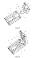
Figures 9 and 10 - the connector in a position before connection in a view without the front cover, -
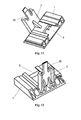
Figures 11 and 12 - placement of the corner in the front cover, -
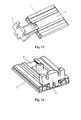
Figures 13 and 14 - a sequence of steps for connection wall part with the cover, -
Figures 15, 16 and17 - a sequence of steps for connection of the individual parts of the blind cover, -
Figure 18 - an example of utilisation of the blind cover for installation of electrical cables. - In
Figure 1 , a blind cover is shown, the cover including a front cover (1), side covers (2, 2'), and connectors (3, 3'). The connectors (3,3') consists of a wall part (4) and a corner (5). The front cover (1) and the side covers (2, 2') are made of an aluminium profile, having a centrally located duct (6) and two side ducts (7, 7') on its internal side. The front cover (1) has both ends cut at an angle of 45° so that the internal length of the front cover (1) is shorter. The side covers (2, 2') are cut on one end at an angle of 45° so that their internal length is shorter. The wall part (4) of the connector (3) is slid into the duct (6) of the front cover (1), and the corner (5) is slid into the duct (6) of the side cover (2). - Structural details of the wall part (4) of the connector are shown in
Figures 2 and3 . The wall part (4) of the connector is composed of a casing (8), a wall installation element (9), and an element for connection with the blind (10). Along the casing (8), two grooves (11, 11') run, intended for mounting the wall part in the duct (6) of the blind cover. In the casing, there is an opening (12) intended for unlocking the connection with the corner (5). The wall installation element (9) has properly formed sockets (13, 13') for heads of bolts or screws and recesses (14, 14') for bolts or screws. Such a shaping of the recesses (14, 14') allows a free assembly of the wall part (4) onto a wall without a necessity for precise preparation of fixing elements in the wall, such as expansion plugs. The element for connection with the blind (10) has an opening (15) for elements connecting the wall part (4) with the roller blind. The casing (8) has a recess (16) from its internal side. - The internal structure of the wall part (4) is shown in
Figure 3 . The recess (16) runs through the whole length and it is terminated in a plate with a recess (17) from the wall side. Through the recess, for instance electrical cables for LED lighting installed from the internal side of the cover may be fed. There is an opening (18) in the casing, located on the axis of the opening (15) in the element for connection of the cover with the blind (10). On the internal surface of the casing (8), there is a system of offsets (19), with fronts facing the wall. The offsets are intended for connection with the corner (5) of the connector. InFigure 4 , a magnification of detail A fromFigure 3 is shown. - The corner (5) of the connector (3), shown in
Figures 5, 6 and7 in three views, consists of two parts (20, 21) perpendicular to one another, and both these parts have an external outline corresponding to the shape of the central duct (6) of the front cover (1) and side covers (2, 2'). The corner (5) has ribs (22, 22', 23, 23', 24, 24') reinforcing its structure, and moreover it has an additional rib (25) reinforcing the connection of both parts of the corner (5). Part (21) has a catch pawl (26) intended for connection of the corner with the wall part (4) of the connector (3). In its terminal part, the catch pawl (26) has a tip (27) in the form of a half of an arrow with a cant from the external side of the corner (5), and from its internal side, a protrusion (28) is formed, intended for engaging the offsets (19) of the wall part (4). At the both sides of the catch pawl (26), there are furrows (29, 29') elongating the catch pawl (26), therefore it is more flexible, what favourably influences its operating qualities. - These recesses are not necessary but they are preferable. In
Figure 8 , a version of the corner (5) without the recesses at the base of the catch pawl (26) is shown. - In
Figure 9 , a connector (3) is shown in a position before connection in a view without the front cover. The catch pawl (26) of the corner is slid into the furrow (16) in the wall part (4), and next, as it is shown inFigure 10 , the tip (27) of the catch pawl (26) slides onto the system of offsets (19) of the wall part (4); then, after pushing to its terminal position, the protrusion (28) on the tip (27) locks itself on one of the offsets (19). - In
Figures 11 and 12 , placement of the corner (5) in the front cover (1) is shown; the corner (5) is slid into the duct (16) of the front cover's profile so that the catch pawl (26) is directed outwards. - In
Figures 13 and 14 , a sequence of steps of introduction of the wall part (4) to the duct (16') in the side cover's profile (2) is shown. The wall part is introduced into the side cover (2) from the side of the perpendicular cant. - In
Figures 15, 16 and17 , a sequence of steps for connection of the individual parts of the blind cover is shown, while, for the sake of clarity, the fact that the side cover (2) is fixed via the wall part (4) to the wall has been omitted. In the first step (Figure 15 ), the front part (1) with the corner (5) is positioned perpendicularly to the side cover (2) with the catch pawl (26) oriented towards the side cover (2). Then, the free end (21) of the corner (5) is slid into the duct (6') of the side cover (2) pushing home, and in this position, the protrusion (28) on the tip (27) engages the offsets (19) in the wall part (4). The assembly of the blind cover is finished, being shown inFigure 17 . - In
Figure 18 , an example of utilisation of the duct (6, 6'), the furrow (16) in the wall part (4), and the ducts in the corner (5) for feeding a low-voltage cable for LED lighting is shown.
Claims (10)
- A blind cover, including a decorative strip and a connector, characterised in that the decorative strip (1, 2, 2') has at least one pass-through duct (6) with a rectangular cross-section from its internal side, while the external wall of the rectangle contains a longitudinal recess forming longitudinal protrusions directed into the duct along both sides, and the connector (3) consists of a wall part (4) and a corner (5), while the wall part (4) is a rectangular prism with the shape adjusted to the shape of the duct (6) of the decorative strip (1, 2, 2'), and two grooves (11, 11') run along the whole casing (8) of the wall part (4), while there is a furrow (16) for the corner's catch pawl (26) along the wall part (4) from its internal side, and there is an opening (12) in the casing (8) of the wall part (4) for unlocking the connection with the corner (5); and moreover there is a system of offsets (19) on the internal surface of the casing (8), with the offset fronts facing the wall, while the corner (5) consists of two rectangular prisms (20, 21) oriented perpendicularly to one another with the shape adjusted to the cross-section of the decorative strip's profile (1, 2, 2'), and a catch pawl (26) with a catch pawl's tip (27) protrudes from one of the rectangular prisms.
- A cover according to claim 1 characterised in that the wall part (4) has additionally elements (9) for installation onto a wall.
- A cover according to claim 1 or 2 characterised in that there are two furrows (29, 29') in the corner (5) at the sides of the base of the catch pawl (26).
- A cover according to claim 1 or 2 or 3 characterised in that the corner (5) has additional reinforcing ribs (22, 22', 23, 23').
- A cover according to claim 1 or 2 or 3 or 4 characterised in that the wall part (4) and the corner (5) have additional ducts for feeding cables.
- A connector for the blind cover characterised in that it consists of a wall part (4) and a corner (5), while the wall part (4) is a rectangular prism with the shape adjusted to the shape of the duct (6) of the decorative strip (1, 2, 2'), and two grooves (11, 11') run along the whole casing (8) of the wall part (4), while there is a furrow (16) for the corner's catch pawl (26) along the wall part (4) from its internal side, and there is an opening (12) in the casing (8) of the wall part (4) for unlocking the connection with the corner (5); and moreover there is a system of offsets (19) on the internal surface of the casing (8), with the offset fronts facing the wall, while the corner (5) consists of two rectangular prisms (20, 21) oriented perpendicularly to one another with the shape adjusted to the cross-section of the decorative strip's profile (1, 2, 2'), and a catch pawl (26) with a catch pawl's tip (27) protrudes from one of the rectangular prisms.
- A connector according to claim 6 characterised in that the wall part (4) has additionally elements (9) for installation onto a wall.
- A connector according to claim 6 or 7 characterised in that there are two furrows (29, 29') in the corner (5) at the sides of the base of the catch pawl (26).
- A connector according to claim 6 or 7 or 8 characterised in that the corner (5) has additional reinforcing ribs (22, 22', 23, 23').
- A connector according to claim 6 or 7 or 8 or 9 characterised in that the wall part (4) and the corner (5) have additional ducts for feeding cables.
Priority Applications (8)
| Application Number | Priority Date | Filing Date | Title |
|---|---|---|---|
| EP14461502.8A EP2891434B1 (en) | 2014-01-07 | 2014-01-07 | Roller blind cover and connector for the roller blind cover |
| PL14461502T PL2891434T3 (en) | 2014-01-07 | 2014-01-07 | Roller blind cover and connector for the roller blind cover |
| PL123646U PL69820Y1 (en) | 2014-01-07 | 2015-01-02 | Fastener of the roller blind shield |
| PL123648U PL70464Y1 (en) | 2014-01-07 | 2015-01-02 | Roller blind shield |
| DE202015000141.6U DE202015000141U1 (en) | 2014-01-07 | 2015-01-05 | Rollo protection device |
| DE202015000143.2U DE202015000143U1 (en) | 2014-01-07 | 2015-01-05 | Connector of the roller blind protective device |
| PL124773U PL70224Y1 (en) | 2014-01-07 | 2016-01-14 | Shackle |
| PL124774U PL69886Y1 (en) | 2014-01-07 | 2016-01-14 | Support |
Applications Claiming Priority (1)
| Application Number | Priority Date | Filing Date | Title |
|---|---|---|---|
| EP14461502.8A EP2891434B1 (en) | 2014-01-07 | 2014-01-07 | Roller blind cover and connector for the roller blind cover |
Publications (2)
| Publication Number | Publication Date |
|---|---|
| EP2891434A1 true EP2891434A1 (en) | 2015-07-08 |
| EP2891434B1 EP2891434B1 (en) | 2017-05-10 |
Family
ID=50179539
Family Applications (1)
| Application Number | Title | Priority Date | Filing Date |
|---|---|---|---|
| EP14461502.8A Not-in-force EP2891434B1 (en) | 2014-01-07 | 2014-01-07 | Roller blind cover and connector for the roller blind cover |
Country Status (3)
| Country | Link |
|---|---|
| EP (1) | EP2891434B1 (en) |
| DE (2) | DE202015000141U1 (en) |
| PL (5) | PL2891434T3 (en) |
Families Citing this family (1)
| Publication number | Priority date | Publication date | Assignee | Title |
|---|---|---|---|---|
| NL2026183B1 (en) * | 2020-07-31 | 2022-04-04 | Coulisse Bv | MOUNTING INTERFACE AND MOUNTING PROFILE FOR MOUNTING A DISPLAY MOUNTING BRACKET ON A SURFACE |
Citations (6)
| Publication number | Priority date | Publication date | Assignee | Title |
|---|---|---|---|---|
| US1873028A (en) * | 1928-08-15 | 1932-08-23 | Pormann Bertha | Combination curtain and shade holder |
| US1892787A (en) * | 1932-08-18 | 1933-01-03 | Abraham M Rubin | Rolling window screen and suspension frame |
| US1906662A (en) * | 1932-09-03 | 1933-05-02 | Jr Charles F Sommerfeld | Shade bracket |
| DE8900259U1 (en) * | 1989-01-11 | 1989-03-02 | Hüppe Form Sonnenschutz- und Raumtrennsysteme GmbH, 2900 Oldenburg | Roller blind, especially for a roof window |
| DE9403196U1 (en) * | 1994-02-25 | 1995-06-29 | Lenze, Günter, Dipl.-Ing., 35457 Lollar | Device for fastening the winding device for material to be wound |
| EP2031177A2 (en) * | 2007-08-31 | 2009-03-04 | Hunter Douglas Industries B.V. | Head rail assembly |
-
2014
- 2014-01-07 PL PL14461502T patent/PL2891434T3/en unknown
- 2014-01-07 EP EP14461502.8A patent/EP2891434B1/en not_active Not-in-force
-
2015
- 2015-01-02 PL PL123648U patent/PL70464Y1/en unknown
- 2015-01-02 PL PL123646U patent/PL69820Y1/en unknown
- 2015-01-05 DE DE202015000141.6U patent/DE202015000141U1/en not_active Expired - Lifetime
- 2015-01-05 DE DE202015000143.2U patent/DE202015000143U1/en not_active Expired - Lifetime
-
2016
- 2016-01-14 PL PL124773U patent/PL70224Y1/en unknown
- 2016-01-14 PL PL124774U patent/PL69886Y1/en unknown
Patent Citations (6)
| Publication number | Priority date | Publication date | Assignee | Title |
|---|---|---|---|---|
| US1873028A (en) * | 1928-08-15 | 1932-08-23 | Pormann Bertha | Combination curtain and shade holder |
| US1892787A (en) * | 1932-08-18 | 1933-01-03 | Abraham M Rubin | Rolling window screen and suspension frame |
| US1906662A (en) * | 1932-09-03 | 1933-05-02 | Jr Charles F Sommerfeld | Shade bracket |
| DE8900259U1 (en) * | 1989-01-11 | 1989-03-02 | Hüppe Form Sonnenschutz- und Raumtrennsysteme GmbH, 2900 Oldenburg | Roller blind, especially for a roof window |
| DE9403196U1 (en) * | 1994-02-25 | 1995-06-29 | Lenze, Günter, Dipl.-Ing., 35457 Lollar | Device for fastening the winding device for material to be wound |
| EP2031177A2 (en) * | 2007-08-31 | 2009-03-04 | Hunter Douglas Industries B.V. | Head rail assembly |
Also Published As
| Publication number | Publication date |
|---|---|
| DE202015000143U1 (en) | 2015-01-30 |
| PL69820Y1 (en) | 2018-03-30 |
| PL69886Y1 (en) | 2018-04-30 |
| PL2891434T3 (en) | 2017-10-31 |
| PL70224Y1 (en) | 2018-09-28 |
| EP2891434B1 (en) | 2017-05-10 |
| DE202015000141U1 (en) | 2015-01-30 |
| PL124773U1 (en) | 2017-07-17 |
| PL124774U1 (en) | 2017-07-17 |
| PL123646U1 (en) | 2015-07-20 |
| PL123648U1 (en) | 2015-07-20 |
| PL70464Y1 (en) | 2019-01-31 |
Similar Documents
| Publication | Publication Date | Title |
|---|---|---|
| US8867235B2 (en) | Configurable conduit body | |
| US5792992A (en) | Expandable surface raceway for wiring | |
| US10686278B2 (en) | Multi-part retaining frame, method for assembling and equipping | |
| CA2793054A1 (en) | Variable-length, adjustable spacer | |
| GB2113021A (en) | Electrical collector rail with connectable adapter | |
| EP3495726A1 (en) | Lighting apparatus, power-supply apparatus, coupling apparatus and lighting system | |
| CN106716739B (en) | Housing for connection to a plug-in connection | |
| CN105143746A (en) | Wire management system | |
| CN116391093A (en) | Mounting rail system with tap-off elements | |
| EP3469166B1 (en) | Wall cladding | |
| EP2891434A1 (en) | Roller blind cover and connector for the roller blind cover | |
| US11223188B2 (en) | Cable tray section | |
| AU2008205446B2 (en) | Mounting box for electrical wiring accessories and assemblies and installations including such mounting box | |
| US11258239B2 (en) | Cable tray section | |
| DE102016124609A1 (en) | Distribution box for installation in a wall opening | |
| US20110290700A1 (en) | Housing, in particular for an electric vehicle charging box | |
| EP2650595A1 (en) | Light strip with luminaire | |
| US20250369597A1 (en) | Light fixture joining system | |
| EP3477805B1 (en) | Cable ladder corner | |
| FI85074C (en) | HOERNSTYCKE FOER ETT LEDNINGSKANALSYSTEM. | |
| US9496694B1 (en) | Easy insertion electrical connector | |
| EP0555688B1 (en) | Fluorescent lamp | |
| KR100711503B1 (en) | Sleeve housing integrated duct | |
| EP3217086A1 (en) | Modular lighting system | |
| US9490617B1 (en) | Easy insertion electrical connector |
Legal Events
| Date | Code | Title | Description |
|---|---|---|---|
| PUAI | Public reference made under article 153(3) epc to a published international application that has entered the european phase |
Free format text: ORIGINAL CODE: 0009012 |
|
| 17P | Request for examination filed |
Effective date: 20140107 |
|
| AK | Designated contracting states |
Kind code of ref document: A1 Designated state(s): AL AT BE BG CH CY CZ DE DK EE ES FI FR GB GR HR HU IE IS IT LI LT LU LV MC MK MT NL NO PL PT RO RS SE SI SK SM TR |
|
| AX | Request for extension of the european patent |
Extension state: BA ME |
|
| R17P | Request for examination filed (corrected) |
Effective date: 20151222 |
|
| RBV | Designated contracting states (corrected) |
Designated state(s): AL AT BE BG CH CY CZ DE DK EE ES FI FR GB GR HR HU IE IS IT LI LT LU LV MC MK MT NL NO PL PT RO RS SE SI SK SM TR |
|
| 17Q | First examination report despatched |
Effective date: 20160713 |
|
| GRAP | Despatch of communication of intention to grant a patent |
Free format text: ORIGINAL CODE: EPIDOSNIGR1 |
|
| INTG | Intention to grant announced |
Effective date: 20170217 |
|
| GRAS | Grant fee paid |
Free format text: ORIGINAL CODE: EPIDOSNIGR3 |
|
| GRAA | (expected) grant |
Free format text: ORIGINAL CODE: 0009210 |
|
| AK | Designated contracting states |
Kind code of ref document: B1 Designated state(s): AL AT BE BG CH CY CZ DE DK EE ES FI FR GB GR HR HU IE IS IT LI LT LU LV MC MK MT NL NO PL PT RO RS SE SI SK SM TR |
|
| REG | Reference to a national code |
Ref country code: GB Ref legal event code: FG4D |
|
| REG | Reference to a national code |
Ref country code: AT Ref legal event code: REF Ref document number: 891397 Country of ref document: AT Kind code of ref document: T Effective date: 20170515 Ref country code: CH Ref legal event code: EP |
|
| REG | Reference to a national code |
Ref country code: IE Ref legal event code: FG4D |
|
| REG | Reference to a national code |
Ref country code: DE Ref legal event code: R096 Ref document number: 602014009630 Country of ref document: DE |
|
| REG | Reference to a national code |
Ref country code: NL Ref legal event code: FP |
|
| REG | Reference to a national code |
Ref country code: LT Ref legal event code: MG4D |
|
| REG | Reference to a national code |
Ref country code: AT Ref legal event code: MK05 Ref document number: 891397 Country of ref document: AT Kind code of ref document: T Effective date: 20170510 |
|
| PG25 | Lapsed in a contracting state [announced via postgrant information from national office to epo] |
Ref country code: GR Free format text: LAPSE BECAUSE OF FAILURE TO SUBMIT A TRANSLATION OF THE DESCRIPTION OR TO PAY THE FEE WITHIN THE PRESCRIBED TIME-LIMIT Effective date: 20170811 Ref country code: LT Free format text: LAPSE BECAUSE OF FAILURE TO SUBMIT A TRANSLATION OF THE DESCRIPTION OR TO PAY THE FEE WITHIN THE PRESCRIBED TIME-LIMIT Effective date: 20170510 Ref country code: AT Free format text: LAPSE BECAUSE OF FAILURE TO SUBMIT A TRANSLATION OF THE DESCRIPTION OR TO PAY THE FEE WITHIN THE PRESCRIBED TIME-LIMIT Effective date: 20170510 Ref country code: FI Free format text: LAPSE BECAUSE OF FAILURE TO SUBMIT A TRANSLATION OF THE DESCRIPTION OR TO PAY THE FEE WITHIN THE PRESCRIBED TIME-LIMIT Effective date: 20170510 Ref country code: HR Free format text: LAPSE BECAUSE OF FAILURE TO SUBMIT A TRANSLATION OF THE DESCRIPTION OR TO PAY THE FEE WITHIN THE PRESCRIBED TIME-LIMIT Effective date: 20170510 Ref country code: NO Free format text: LAPSE BECAUSE OF FAILURE TO SUBMIT A TRANSLATION OF THE DESCRIPTION OR TO PAY THE FEE WITHIN THE PRESCRIBED TIME-LIMIT Effective date: 20170810 Ref country code: ES Free format text: LAPSE BECAUSE OF FAILURE TO SUBMIT A TRANSLATION OF THE DESCRIPTION OR TO PAY THE FEE WITHIN THE PRESCRIBED TIME-LIMIT Effective date: 20170510 |
|
| PG25 | Lapsed in a contracting state [announced via postgrant information from national office to epo] |
Ref country code: RS Free format text: LAPSE BECAUSE OF FAILURE TO SUBMIT A TRANSLATION OF THE DESCRIPTION OR TO PAY THE FEE WITHIN THE PRESCRIBED TIME-LIMIT Effective date: 20170510 Ref country code: SE Free format text: LAPSE BECAUSE OF FAILURE TO SUBMIT A TRANSLATION OF THE DESCRIPTION OR TO PAY THE FEE WITHIN THE PRESCRIBED TIME-LIMIT Effective date: 20170510 Ref country code: LV Free format text: LAPSE BECAUSE OF FAILURE TO SUBMIT A TRANSLATION OF THE DESCRIPTION OR TO PAY THE FEE WITHIN THE PRESCRIBED TIME-LIMIT Effective date: 20170510 Ref country code: BG Free format text: LAPSE BECAUSE OF FAILURE TO SUBMIT A TRANSLATION OF THE DESCRIPTION OR TO PAY THE FEE WITHIN THE PRESCRIBED TIME-LIMIT Effective date: 20170810 Ref country code: IS Free format text: LAPSE BECAUSE OF FAILURE TO SUBMIT A TRANSLATION OF THE DESCRIPTION OR TO PAY THE FEE WITHIN THE PRESCRIBED TIME-LIMIT Effective date: 20170910 |
|
| REG | Reference to a national code |
Ref country code: FR Ref legal event code: PLFP Year of fee payment: 5 |
|
| PG25 | Lapsed in a contracting state [announced via postgrant information from national office to epo] |
Ref country code: CZ Free format text: LAPSE BECAUSE OF FAILURE TO SUBMIT A TRANSLATION OF THE DESCRIPTION OR TO PAY THE FEE WITHIN THE PRESCRIBED TIME-LIMIT Effective date: 20170510 Ref country code: RO Free format text: LAPSE BECAUSE OF FAILURE TO SUBMIT A TRANSLATION OF THE DESCRIPTION OR TO PAY THE FEE WITHIN THE PRESCRIBED TIME-LIMIT Effective date: 20170510 Ref country code: SK Free format text: LAPSE BECAUSE OF FAILURE TO SUBMIT A TRANSLATION OF THE DESCRIPTION OR TO PAY THE FEE WITHIN THE PRESCRIBED TIME-LIMIT Effective date: 20170510 Ref country code: DK Free format text: LAPSE BECAUSE OF FAILURE TO SUBMIT A TRANSLATION OF THE DESCRIPTION OR TO PAY THE FEE WITHIN THE PRESCRIBED TIME-LIMIT Effective date: 20170510 Ref country code: EE Free format text: LAPSE BECAUSE OF FAILURE TO SUBMIT A TRANSLATION OF THE DESCRIPTION OR TO PAY THE FEE WITHIN THE PRESCRIBED TIME-LIMIT Effective date: 20170510 |
|
| REG | Reference to a national code |
Ref country code: DE Ref legal event code: R097 Ref document number: 602014009630 Country of ref document: DE |
|
| PG25 | Lapsed in a contracting state [announced via postgrant information from national office to epo] |
Ref country code: SM Free format text: LAPSE BECAUSE OF FAILURE TO SUBMIT A TRANSLATION OF THE DESCRIPTION OR TO PAY THE FEE WITHIN THE PRESCRIBED TIME-LIMIT Effective date: 20170510 Ref country code: IT Free format text: LAPSE BECAUSE OF FAILURE TO SUBMIT A TRANSLATION OF THE DESCRIPTION OR TO PAY THE FEE WITHIN THE PRESCRIBED TIME-LIMIT Effective date: 20170510 |
|
| PGFP | Annual fee paid to national office [announced via postgrant information from national office to epo] |
Ref country code: LU Payment date: 20180103 Year of fee payment: 5 |
|
| PLBE | No opposition filed within time limit |
Free format text: ORIGINAL CODE: 0009261 |
|
| STAA | Information on the status of an ep patent application or granted ep patent |
Free format text: STATUS: NO OPPOSITION FILED WITHIN TIME LIMIT |
|
| PGFP | Annual fee paid to national office [announced via postgrant information from national office to epo] |
Ref country code: NL Payment date: 20180124 Year of fee payment: 5 |
|
| 26N | No opposition filed |
Effective date: 20180213 |
|
| PGFP | Annual fee paid to national office [announced via postgrant information from national office to epo] |
Ref country code: GB Payment date: 20180104 Year of fee payment: 5 Ref country code: DE Payment date: 20180103 Year of fee payment: 5 |
|
| PG25 | Lapsed in a contracting state [announced via postgrant information from national office to epo] |
Ref country code: SI Free format text: LAPSE BECAUSE OF FAILURE TO SUBMIT A TRANSLATION OF THE DESCRIPTION OR TO PAY THE FEE WITHIN THE PRESCRIBED TIME-LIMIT Effective date: 20170510 |
|
| PGFP | Annual fee paid to national office [announced via postgrant information from national office to epo] |
Ref country code: BE Payment date: 20180103 Year of fee payment: 5 Ref country code: FR Payment date: 20180103 Year of fee payment: 5 Ref country code: PL Payment date: 20180102 Year of fee payment: 5 |
|
| REG | Reference to a national code |
Ref country code: CH Ref legal event code: PL |
|
| REG | Reference to a national code |
Ref country code: IE Ref legal event code: MM4A |
|
| PG25 | Lapsed in a contracting state [announced via postgrant information from national office to epo] |
Ref country code: LI Free format text: LAPSE BECAUSE OF NON-PAYMENT OF DUE FEES Effective date: 20180131 Ref country code: CH Free format text: LAPSE BECAUSE OF NON-PAYMENT OF DUE FEES Effective date: 20180131 |
|
| PG25 | Lapsed in a contracting state [announced via postgrant information from national office to epo] |
Ref country code: IE Free format text: LAPSE BECAUSE OF NON-PAYMENT OF DUE FEES Effective date: 20180107 |
|
| PG25 | Lapsed in a contracting state [announced via postgrant information from national office to epo] |
Ref country code: MC Free format text: LAPSE BECAUSE OF FAILURE TO SUBMIT A TRANSLATION OF THE DESCRIPTION OR TO PAY THE FEE WITHIN THE PRESCRIBED TIME-LIMIT Effective date: 20170510 |
|
| REG | Reference to a national code |
Ref country code: DE Ref legal event code: R119 Ref document number: 602014009630 Country of ref document: DE |
|
| REG | Reference to a national code |
Ref country code: NL Ref legal event code: MM Effective date: 20190201 |
|
| GBPC | Gb: european patent ceased through non-payment of renewal fee |
Effective date: 20190107 |
|
| PG25 | Lapsed in a contracting state [announced via postgrant information from national office to epo] |
Ref country code: LU Free format text: LAPSE BECAUSE OF NON-PAYMENT OF DUE FEES Effective date: 20190107 |
|
| REG | Reference to a national code |
Ref country code: BE Ref legal event code: MM Effective date: 20190131 |
|
| PG25 | Lapsed in a contracting state [announced via postgrant information from national office to epo] |
Ref country code: FR Free format text: LAPSE BECAUSE OF NON-PAYMENT OF DUE FEES Effective date: 20190131 Ref country code: NL Free format text: LAPSE BECAUSE OF NON-PAYMENT OF DUE FEES Effective date: 20190201 Ref country code: DE Free format text: LAPSE BECAUSE OF NON-PAYMENT OF DUE FEES Effective date: 20190801 |
|
| PG25 | Lapsed in a contracting state [announced via postgrant information from national office to epo] |
Ref country code: BE Free format text: LAPSE BECAUSE OF NON-PAYMENT OF DUE FEES Effective date: 20190131 |
|
| PG25 | Lapsed in a contracting state [announced via postgrant information from national office to epo] |
Ref country code: GB Free format text: LAPSE BECAUSE OF NON-PAYMENT OF DUE FEES Effective date: 20190107 |
|
| PG25 | Lapsed in a contracting state [announced via postgrant information from national office to epo] |
Ref country code: MT Free format text: LAPSE BECAUSE OF NON-PAYMENT OF DUE FEES Effective date: 20180107 |
|
| PG25 | Lapsed in a contracting state [announced via postgrant information from national office to epo] |
Ref country code: TR Free format text: LAPSE BECAUSE OF FAILURE TO SUBMIT A TRANSLATION OF THE DESCRIPTION OR TO PAY THE FEE WITHIN THE PRESCRIBED TIME-LIMIT Effective date: 20170510 |
|
| PG25 | Lapsed in a contracting state [announced via postgrant information from national office to epo] |
Ref country code: PT Free format text: LAPSE BECAUSE OF FAILURE TO SUBMIT A TRANSLATION OF THE DESCRIPTION OR TO PAY THE FEE WITHIN THE PRESCRIBED TIME-LIMIT Effective date: 20170510 |
|
| PG25 | Lapsed in a contracting state [announced via postgrant information from national office to epo] |
Ref country code: MK Free format text: LAPSE BECAUSE OF NON-PAYMENT OF DUE FEES Effective date: 20170510 Ref country code: CY Free format text: LAPSE BECAUSE OF FAILURE TO SUBMIT A TRANSLATION OF THE DESCRIPTION OR TO PAY THE FEE WITHIN THE PRESCRIBED TIME-LIMIT Effective date: 20170510 Ref country code: HU Free format text: LAPSE BECAUSE OF FAILURE TO SUBMIT A TRANSLATION OF THE DESCRIPTION OR TO PAY THE FEE WITHIN THE PRESCRIBED TIME-LIMIT; INVALID AB INITIO Effective date: 20140107 |
|
| PG25 | Lapsed in a contracting state [announced via postgrant information from national office to epo] |
Ref country code: AL Free format text: LAPSE BECAUSE OF FAILURE TO SUBMIT A TRANSLATION OF THE DESCRIPTION OR TO PAY THE FEE WITHIN THE PRESCRIBED TIME-LIMIT Effective date: 20170510 |
|
| PG25 | Lapsed in a contracting state [announced via postgrant information from national office to epo] |
Ref country code: PL Free format text: LAPSE BECAUSE OF NON-PAYMENT OF DUE FEES Effective date: 20190107 |