EP2890443B1 - Connectorized cochlear implant systems - Google Patents
Connectorized cochlear implant systems Download PDFInfo
- Publication number
- EP2890443B1 EP2890443B1 EP13745990.5A EP13745990A EP2890443B1 EP 2890443 B1 EP2890443 B1 EP 2890443B1 EP 13745990 A EP13745990 A EP 13745990A EP 2890443 B1 EP2890443 B1 EP 2890443B1
- Authority
- EP
- European Patent Office
- Prior art keywords
- cochlear implant
- sound processor
- module
- implantable
- optical
- Prior art date
- Legal status (The legal status is an assumption and is not a legal conclusion. Google has not performed a legal analysis and makes no representation as to the accuracy of the status listed.)
- Not-in-force
Links
Images


Classifications
-
- A—HUMAN NECESSITIES
- A61—MEDICAL OR VETERINARY SCIENCE; HYGIENE
- A61N—ELECTROTHERAPY; MAGNETOTHERAPY; RADIATION THERAPY; ULTRASOUND THERAPY
- A61N1/00—Electrotherapy; Circuits therefor
- A61N1/02—Details
- A61N1/04—Electrodes
- A61N1/05—Electrodes for implantation or insertion into the body, e.g. heart electrode
- A61N1/0526—Head electrodes
- A61N1/0541—Cochlear electrodes
-
- A—HUMAN NECESSITIES
- A61—MEDICAL OR VETERINARY SCIENCE; HYGIENE
- A61N—ELECTROTHERAPY; MAGNETOTHERAPY; RADIATION THERAPY; ULTRASOUND THERAPY
- A61N1/00—Electrotherapy; Circuits therefor
- A61N1/18—Applying electric currents by contact electrodes
- A61N1/32—Applying electric currents by contact electrodes alternating or intermittent currents
- A61N1/36—Applying electric currents by contact electrodes alternating or intermittent currents for stimulation
- A61N1/36036—Applying electric currents by contact electrodes alternating or intermittent currents for stimulation of the outer, middle or inner ear
- A61N1/36038—Cochlear stimulation
-
- A—HUMAN NECESSITIES
- A61—MEDICAL OR VETERINARY SCIENCE; HYGIENE
- A61N—ELECTROTHERAPY; MAGNETOTHERAPY; RADIATION THERAPY; ULTRASOUND THERAPY
- A61N1/00—Electrotherapy; Circuits therefor
- A61N1/18—Applying electric currents by contact electrodes
- A61N1/32—Applying electric currents by contact electrodes alternating or intermittent currents
- A61N1/36—Applying electric currents by contact electrodes alternating or intermittent currents for stimulation
- A61N1/372—Arrangements in connection with the implantation of stimulators
-
- A—HUMAN NECESSITIES
- A61—MEDICAL OR VETERINARY SCIENCE; HYGIENE
- A61N—ELECTROTHERAPY; MAGNETOTHERAPY; RADIATION THERAPY; ULTRASOUND THERAPY
- A61N1/00—Electrotherapy; Circuits therefor
- A61N1/18—Applying electric currents by contact electrodes
- A61N1/32—Applying electric currents by contact electrodes alternating or intermittent currents
- A61N1/36—Applying electric currents by contact electrodes alternating or intermittent currents for stimulation
- A61N1/372—Arrangements in connection with the implantation of stimulators
- A61N1/37211—Means for communicating with stimulators
- A61N1/37217—Means for communicating with stimulators characterised by the communication link, e.g. acoustic or tactile
-
- A—HUMAN NECESSITIES
- A61—MEDICAL OR VETERINARY SCIENCE; HYGIENE
- A61N—ELECTROTHERAPY; MAGNETOTHERAPY; RADIATION THERAPY; ULTRASOUND THERAPY
- A61N1/00—Electrotherapy; Circuits therefor
- A61N1/18—Applying electric currents by contact electrodes
- A61N1/32—Applying electric currents by contact electrodes alternating or intermittent currents
- A61N1/36—Applying electric currents by contact electrodes alternating or intermittent currents for stimulation
- A61N1/372—Arrangements in connection with the implantation of stimulators
- A61N1/378—Electrical supply
-
- A—HUMAN NECESSITIES
- A61—MEDICAL OR VETERINARY SCIENCE; HYGIENE
- A61N—ELECTROTHERAPY; MAGNETOTHERAPY; RADIATION THERAPY; ULTRASOUND THERAPY
- A61N1/00—Electrotherapy; Circuits therefor
- A61N1/18—Applying electric currents by contact electrodes
- A61N1/32—Applying electric currents by contact electrodes alternating or intermittent currents
- A61N1/36—Applying electric currents by contact electrodes alternating or intermittent currents for stimulation
- A61N1/372—Arrangements in connection with the implantation of stimulators
- A61N1/378—Electrical supply
- A61N1/3787—Electrical supply from an external energy source
-
- H—ELECTRICITY
- H04—ELECTRIC COMMUNICATION TECHNIQUE
- H04R—LOUDSPEAKERS, MICROPHONES, GRAMOPHONE PICK-UPS OR LIKE ACOUSTIC ELECTROMECHANICAL TRANSDUCERS; ELECTRIC HEARING AIDS; PUBLIC ADDRESS SYSTEMS
- H04R25/00—Electric hearing aids
- H04R25/55—Electric hearing aids using an external connection, either wireless or wired
- H04R25/554—Electric hearing aids using an external connection, either wireless or wired using a wireless connection, e.g. between microphone and amplifier or using Tcoils
-
- H—ELECTRICITY
- H04—ELECTRIC COMMUNICATION TECHNIQUE
- H04R—LOUDSPEAKERS, MICROPHONES, GRAMOPHONE PICK-UPS OR LIKE ACOUSTIC ELECTROMECHANICAL TRANSDUCERS; ELECTRIC HEARING AIDS; PUBLIC ADDRESS SYSTEMS
- H04R25/00—Electric hearing aids
- H04R25/60—Mounting or interconnection of hearing aid parts, e.g. inside tips, housings or to ossicles
- H04R25/604—Mounting or interconnection of hearing aid parts, e.g. inside tips, housings or to ossicles of acoustic or vibrational transducers
- H04R25/606—Mounting or interconnection of hearing aid parts, e.g. inside tips, housings or to ossicles of acoustic or vibrational transducers acting directly on the eardrum, the ossicles or the skull, e.g. mastoid, tooth, maxillary or mandibular bone, or mechanically stimulating the cochlea, e.g. at the oval window
-
- H—ELECTRICITY
- H04—ELECTRIC COMMUNICATION TECHNIQUE
- H04R—LOUDSPEAKERS, MICROPHONES, GRAMOPHONE PICK-UPS OR LIKE ACOUSTIC ELECTROMECHANICAL TRANSDUCERS; ELECTRIC HEARING AIDS; PUBLIC ADDRESS SYSTEMS
- H04R2225/00—Details of deaf aids covered by H04R25/00, not provided for in any of its subgroups
- H04R2225/57—Aspects of electrical interconnection between hearing aid parts
-
- H—ELECTRICITY
- H04—ELECTRIC COMMUNICATION TECHNIQUE
- H04R—LOUDSPEAKERS, MICROPHONES, GRAMOPHONE PICK-UPS OR LIKE ACOUSTIC ELECTROMECHANICAL TRANSDUCERS; ELECTRIC HEARING AIDS; PUBLIC ADDRESS SYSTEMS
- H04R2460/00—Details of hearing devices, i.e. of ear- or headphones covered by H04R1/10 or H04R5/033 but not provided for in any of their subgroups, or of hearing aids covered by H04R25/00 but not provided for in any of its subgroups
- H04R2460/03—Aspects of the reduction of energy consumption in hearing devices
-
- H—ELECTRICITY
- H04—ELECTRIC COMMUNICATION TECHNIQUE
- H04R—LOUDSPEAKERS, MICROPHONES, GRAMOPHONE PICK-UPS OR LIKE ACOUSTIC ELECTROMECHANICAL TRANSDUCERS; ELECTRIC HEARING AIDS; PUBLIC ADDRESS SYSTEMS
- H04R25/00—Electric hearing aids
- H04R25/60—Mounting or interconnection of hearing aid parts, e.g. inside tips, housings or to ossicles
- H04R25/609—Mounting or interconnection of hearing aid parts, e.g. inside tips, housings or to ossicles of circuitry
Definitions
- Conventional cochlear implant systems include various components configured to be implanted within a patient (e.g., a cochlear implant, an antenna, and an electrode lead) and various components configured to be located external to the patient (e.g., a sound processor, a battery, and a microphone).
- a conventional cochlear implant system e.g., a sound processor, a battery, and a microphone
- the external components of a conventional cochlear implant system are often relatively large, bulky, and aesthetically unpleasing.
- various fully implantable cochlear implant systems have been described in which the sound processor and one or more other components typically located external to the patient (i.e., the battery and/or the microphone) are also implanted within the patient. In these configurations, the patient may enjoy cochlear implant functionality with little or no externally located components for various periods throughout the day.
- some patients cannot initially be fitted with a fully implantable cochlear implant system.
- some patients e.g., pediatric patients
- Other patients may be unable to be fitted with a fully implantable cochlear implant system for technological, logistical, and/or financial reasons.
- these patients may be initially fitted with a conventional cochlear implant system.
- they may become eligible for a fully implantable cochlear implant system.
- Such an upgrade would typically require a patient to undergo a surgical procedure in which all of the already implanted components of the conventional cochlear implant system are replaced with the new fully implantable cochlear implant system components.
- this surgical procedure could potentially cause damage to one or more of the patient's auditory structures and thereby negate any benefits that could be provided by the fully implantable cochlear implant system.
- US 2011/0295331 A1 relates to an implantable system for optical or combined optical and electrical stimulation of the cochlea according to the preamble of claim 1, wherein there is optical transmission of the optical stimulation signals from the sound processor module to the optical stimulation site.
- Connectorized cochlear implant systems are described herein.
- the invention relates to a connectorized cochlear implant system as defined in claim 1.
- the systems described herein may facilitate individual replacement of one or more components of a cochlear implant system after they have been implanted within a patient.
- a patient may be initially fitted with a connectorized cochlear implant system that includes a cochlear implant module and an implantable sound processor module communicatively coupled by way of an optical connector assembly.
- the optical connector assembly is permanently coupled to the implantable sound processor module and removably connected to the cochlear implant module. After some time thereafter (e.g., in a few years), it may become desirable to replace the implantable sound processor module with a new (e.g., upgraded) sound processor module.
- the patient may undergo a minimally invasive surgical procedure during which the optical connector assembly is disconnected from the cochlear implant module.
- the implantable sound processor module and optical connector assembly may then be removed from the patient and replaced with the new implantable sound processor module (with a new optical connector assembly permanently coupled thereto that may be removably connected to the cochlear implant module).
- the remaining implanted components i.e., the cochlear implant module and an electrode lead coupled to the cochlear implant module
- the remaining implanted components i.e., the cochlear implant module and an electrode lead coupled to the cochlear implant module
- the optical connector assemblies described herein may include one or more optical fibers configured to facilitate optical transmission of data and power from sound processor circuitry included in an implantable sound processor module to cochlear implant circuitry included in a cochlear implant module.
- Optical transmission (as opposed to electrical transmission) of data and power may be advantageous for many reasons. For example, it may be difficult to avoid DC current leakage (which could be harmful to the patient) with electrical transmission of data and power between sound processor circuitry included in an implantable sound processor module and cochlear implant circuitry included in a cochlear implant module due to the requirement for small geometric dimensions for an implant at the head-level.
- Optical transmission of data and power may obviate DC current leakage, thereby making optical transmission safer and more reliable than electrical transmission.
- Optical transmission may also advantageously have virtually unlimited data transmission bandwidth capabilities and may be relatively more efficient from a power transmission perspective than electrical transmission.
- FIG. 1 illustrates an exemplary connectorized cochlear implant system 100.
- connectorized cochlear implant system 100 may include various components configured to be implanted within the patient.
- connectorized cochlear implant system 100 may be referred to as a "fully implantable cochlear implant system.”
- connectorized cochlear implant system 100 may include an implantable sound processor module 102, a cochlear implant module 104, an optical connector assembly 106, and a lead 108 having a plurality of electrodes 110 disposed thereon.
- Implantable sound processor module 102 may include any suitable housing, overmold, or case (e.g., a hermetically sealed housing) configured to house sound processor components.
- implantable sound processor module 102 may house sound processor circuitry 112, a battery 114, and an optical feedthrough assembly 116.
- Cochlear implant module 102 may include any suitable housing, overmold, or case (e.g., a hermetically sealed housing) configured to house various cochlear implant components.
- cochlear implant module 102 may house cochlear implant circuitry 118 and an optical feedthrough assembly 120. Additional or alternative components may be housed within implantable sound processor module 102 and/or cochlear implant module 104 as may serve a particular implementation.
- Sound processor circuitry 112 may be configured to direct cochlear implant circuitry 118 to generate and apply electrical stimulation (also referred to herein as "stimulation current") representative of one or more audio signals (e.g., one or more audio signals detected by a microphone (not shown), input by way of an auxiliary audio input port, etc.) to one or more stimulation sites associated with an auditory pathway (e.g., the auditory nerve) of the patient.
- electrical stimulation also referred to herein as "stimulation current” representative of one or more audio signals (e.g., one or more audio signals detected by a microphone (not shown), input by way of an auxiliary audio input port, etc.) to one or more stimulation sites associated with an auditory pathway (e.g., the auditory nerve) of the patient.
- exemplary stimulation sites include, but are not limited to, one or more locations within the cochlea, the cochlear nucleus, the inferior colliculus, and/or any other nuclei in the auditory pathway.
- sound processor circuitry 112 may process the one or more audio signals in accordance with a selected sound processing strategy or program to generate appropriate stimulation parameters for controlling cochlear implant circuitry 118. As will be described below, sound processor circuitry 112 may optically transmit data (e.g., one or more stimulation parameters) to cochlear implant circuitry 118 by way of one or more optical fibers included within optical connector assembly 106.
- data e.g., one or more stimulation parameters
- Battery 114 may be electrically coupled to sound processor circuitry, as illustrated by connection 122. In some examples, battery 114 may provide operating power for both sound processor circuitry 112 and cochlear implant circuitry 118. As will be described below, sound processor circuitry 112 may optically transmit power provided by battery 114 to cochlear implant circuitry 118 by way of one or more optical fibers included within optical connector assembly 106.
- Optical feedthrough assembly 116 may be communicatively coupled to sound processor circuitry 112 by way of a communication link 124.
- Communication link 124 may include any type of communication link (e.g., an optical communication link, an electrical communication link, etc.) as may serve a particular implementation.
- optical feedthrough assembly 116 may optically connect one or more optical fibers included in optical connector assembly 106 to sound processor circuitry 112, thereby facilitating optical transmission of data and power by sound processor circuitry 112 to cochlear implant circuitry 118.
- Cochlear implant module 104 may be implemented by any type of implantable stimulator that may be used in association with the systems and methods described herein.
- cochlear implant module 104 may be implemented by an implantable cochlear stimulator.
- cochlear implant module 104 may be implemented by a brainstem implant and/or any other type of cochlear implant that may be implanted within a patient.
- cochlear implant module 104 may include cochlear implant circuitry 118 and optical feedthrough assembly 120 disposed therein.
- Cochlear implant circuitry 118 may be configured to generate electrical stimulation representative of an audio signal processed by sound processor circuitry 112 in accordance with one or more stimulation parameters transmitted thereto by sound processor circuitry 112.
- Cochlear implant circuitry 118 may be further configured to apply the electrical stimulation to one or more stimulation sites within the patient via one or more electrodes 110 disposed along lead 108.
- cochlear implant circuitry 118 may include a plurality of independent current sources each associated with a channel defined by one or more of electrodes 110. In this manner, different stimulation current levels may be applied to multiple stimulation sites simultaneously by way of multiple electrodes 110.
- cochlear implant module 104 may be coupled to lead 108.
- Lead 108 may be coupled to cochlear implant module 104 in any suitable manner.
- a proximal end of lead 108 may be integrated into or otherwise permanently coupled to cochlear implant module 104 such that the one or more wires disposed within lead 108 and associated with electrodes 110 may pass through cochlear implant module 104 to cochlear implant circuitry 118 by way of an electrical connection 126.
- Optical feedthrough assembly 120 may be communicatively coupled to cochlear implant circuitry 118 by way of a communication link 128.
- Communication link 128 may include any type of communication link (e.g., an optical communication link, an electrical communication link, etc.) as may serve a particular implementation.
- optical feedthrough assembly 120 may optically connect one or more optical fibers included in optical connector assembly 106 to cochlear implant circuitry 118, thereby facilitating optical transmission of data and power by sound processor circuitry 112 to cochlear implant circuitry 118.
- Optical connector assembly 106 may include a cable 130 and a modular connector 132 disposed at a distal end of cable 130.
- Cable 130 and modular connector 132 may each be made out of any suitable biocompatible material.
- FIG. 2 shows optical connector assembly 106 in more detail.
- cable 130 may house optical fibers 202-1 and 202-2 (collectively "optical fibers 202").
- optical fibers 202 are shown as being housed within cable 130 for illustrative purposes. It will be recognized that any other number of optical fibers (e.g., only one) may be housed within cable 130 as may serve a particular implementation.
- One or more of optical fibers 202 may facilitate optical transmission of data and power from sound processor circuitry 112 to cochlear implant circuitry 118 while implantable sound processor module 102 is removably coupled to cochlear implant module 104 by way of optical connector assembly 106.
- one or more of optical fibers 202 may facilitate optical transmission of data (e.g., back telemetry data) from cochlear implant circuitry 118 to sound processor circuitry 112 while implantable sound processor module 102 is removably coupled to cochlear implant module 104 by way of optical connector assembly 106.
- data e.g., back telemetry data
- Modular connector 132 may include any type of connector configured to be removably connected to any of the modules or other suitable components described herein (e.g., cochlear implant module 104).
- modular connector 132 may include a plug apparatus configured to plug into a corresponding receptacle associated with a module (e.g., cochlear implant module 104).
- the receptacle associated with the module may be integrated into the module (e.g., into an optical feedthrough assembly included within the module), coupled to a distal end of a cable connected to the module, or otherwise associated with the module.
- references to modular connector 132 being "removably connected" to a particular component refer to the modular connector 132 being capable of being relatively easily and/or readily disconnected (e.g., unplugged) from the particular component by a surgeon or other person in a way that does not damage either the modular connector 132 or the particular component.
- a proximal end of cable 130 may be permanently coupled to implantable sound processor module 102.
- references to a proximal end of a cable being "permanently" coupled to a module refers to the proximal end of the cable being integrated into or otherwise affixed to the module such that the cable is not meant to be removed from the module by a user.
- proximal end of cable 130 is permanently coupled to implantable sound processor module 102 by being permanently attached to optical feedthrough assembly 116. In this configuration, optical feedthrough assembly 116 optically connects the one or more optical fibers disposed in cable 130 to sound processor circuitry 112.
- modular connector 132 is configured to removably connect to cochlear implant module 104.
- optical feedthrough assembly 120 optically connects the one or more optical fibers disposed in cable 130 to cochlear implant circuitry 118.
- implantable sound processor module 102 may be removably coupled to cochlear implant module 104 by removably connecting modular connector 132 to cochlear implant module 104.
- sound processor circuitry 112 may optically transmit data (e.g., one or more stimulation parameters) and power (e.g., power supplied by battery 114) to cochlear implant circuitry 118. This may be done in any suitable manner. For example, the data and/or power may be optically modulated and transmitted by way of one or more optical fibers disposed within cable 130. Cochlear implant circuitry 118 may likewise transmit data back to sound processor circuitry 112 while implantable sound processor module 102 is removably coupled to cochlear implant module 104.
- data e.g., one or more stimulation parameters
- power e.g., power supplied by battery 114
- Cochlear implant circuitry 118 may likewise transmit data back to sound processor circuitry 112 while implantable sound processor module 102 is removably coupled to cochlear implant module 104.
- FIG. 3 shows connectorized cochlear implant system 100 after modular connector 132 has been disconnected from cochlear implant module 104. As shown, implantable sound processor module 102 is no longer coupled to cochlear implant module 104. In some examples, a different component (e.g., an antenna or a different implantable sound processor module) may be coupled to cochlear implant module 104 in place of implantable sound processor module 102.
- a different component e.g., an antenna or a different implantable sound processor module
- FIG. 4 illustrates another exemplary connectorized cochlear implant system 400.
- Connectorized cochlear implant system 400 is similar to connectorized cochlear implant system 100 in that it includes implantable sound processor module 102, cochlear implant module 104, and optical connector assembly 106.
- optical connector assembly 106 i.e., a proximal end of cable 130
- modular connector 132 is configured to removably connect to implantable sound processor module 102.
- optical feedthrough assembly 116 optically connects the one or more optical fibers disposed in cable 130 to sound processor circuitry 112.
- implantable sound processor module 102 may be removably coupled to cochlear implant module 104 by removably connecting modular connector 132 to implantable sound processor module 102.
- FIG. 5 illustrates another exemplary connectorized cochlear implant system 500.
- connectorized cochlear implant system 500 includes an optical connector assembly 502 having modular connectors 506-1 and 506-2 (collectively "modular connectors 506") disposed at both ends of a cable 504 that houses one or more optical fibers.
- Modular connector 506-1 is configured to removably connect to implantable sound processor module 102
- modular connector 506-2 is configured to removably connect to cochlear implant module 104. While modular connectors 506 are both in a connected state, sound processor circuitry 112 may optically transmit data and/or power to cochlear implant circuitry 118 and cochlear implant circuitry 118 may transmit data to sound processor circuitry 112.
- battery 114 may be included within implantable sound processor module 102. In some alternative examples, battery 114 may be separate from (i.e., not included in) implantable sound processor module 102.
- FIG. 6 shows an exemplary connectorized cochlear implant system 600 in which an implantable battery 602 is located outside implantable sound processor module 102. In this configuration, implantable battery 602 may be coupled to sound processor circuitry 112 by way of a power link 604, which may include any suitable link (e.g., an electrical link, an optical link, etc.) configured to facilitate transmission of power.
- a power link 604 may include any suitable link (e.g., an electrical link, an optical link, etc.) configured to facilitate transmission of power.
- both implantable sound processor module 102 and implantable battery 602 are implanted within the head of the patient.
- implantable sound processor module 102 may be implanted within the head of the patient and implantable battery 602 may be implanted within the chest of the patient (or in any other suitable location capable of being implanted with a relatively large battery).
- power link 604 may be implemented by a cable and/or one or wires tunneled from the chest to the head.
- implantable sound processor module 102 may be decoupled from cochlear implant module 104 so that another component may be removably coupled to cochlear implant module 104.
- cochlear circuitry 118 may be desirable for cochlear circuitry 118 to communicate with a sound processor located external to the patient.
- cochlear implant module 104 may be removably connected to an antenna configured to wirelessly communicate with the externally located sound processor.
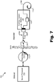
- FIG. 7 shows an exemplary configuration 700 in which an antenna 702 (e.g., a coil and/or one or more wireless communication components) has been removably coupled to cochlear implant module 104 in place of implantable sound processor module 102.
- an optical connector assembly 704 having a cable 706 and a modular connector 708 is permanently coupled to antenna 702.
- modular connector 708 may be removably connected to cochlear implant module 104.
- antenna 702 is communicatively coupled to cochlear implant circuitry 118.
- antenna 702 may facilitate wireless communication between an externally located sound processor 710 and cochlear implant circuitry 118.
- Sound processor 710 may include or be implemented by a behind-the-ear (“BTE”) unit, a body worn device, an electro-acoustic stimulation (“EAS”) device, and/or any other sound processing unit as may serve a particular implementation.
- BTE behind-the-ear
- EAS electro-acoustic stimulation
- Sound processor 710 may be communicatively coupled to a headpiece 712, which may include an external antenna 714 (e.g., a coil and/or one or more wireless communication components). Headpiece 712 may be configured to be affixed to the patient's head and positioned such that external antenna 714 is communicatively coupled to implanted antenna 702 by way of a wireless communication link 716 (which may include a bi-directional communication link and/or one or more dedicated unidirectional communication links as may serve a particular implementation). In this configuration, data and/or power may be wirelessly transmitted between sound processor 710 and cochlear implant circuitry 118 via the wireless communication link 716.
- an external antenna 714 e.g., a coil and/or one or more wireless communication components
- Headpiece 712 may be configured to be affixed to the patient's head and positioned such that external antenna 714 is communicatively coupled to implanted antenna 702 by way of a wireless communication link 716 (which may include a bi-directional communication link
- implantable sound processor module 102 may be activated (i.e., turned on) in any suitable manner (e.g., by utilizing any of the techniques described in WO 2011/095229 A1 , which application is incorporated herein by reference in its entirety) by any suitable activation means. Likewise, implantable sound processor module 102 may be deactivated (e.g., to conserve power or for any other reason) using any of the techniques described in WO 2011/095229 A1 or in any other suitable manner.
- implantable sound processor module 102 may be configured to detect a fault in the connection of optical connector module 106 to either implantable sound processor module 102 or cochlear implant module 104 (e.g., a short or open circuit in the connection). In response, implantable sound processor module 102 may initiate a shut down procedure in which implantable sound processor module 102 safely shuts down and notifies a user of the connection fault.
- cochlear implant circuitry 118 may be configured to automatically detect that a particular component is connected to cochlear implant module 104 by way of optical connector assembly 106 and operate in accordance with a protocol corresponds to the particular component. For example, cochlear implant circuitry 118 may detect that implantable antenna 702 is connected to cochlear implant module 104, and, in response, operate in accordance with a radio frequency ("RF") inductive link communication protocol while implantable antenna 702 is connected to cochlear implant module 104.
- RF inductive link communication protocol refers to any suitable communication protocol that may be used to wirelessly communicate with an external sound processor (e.g., sound processor 710).
- cochlear implant circuitry 118 may detect a disconnection of implantable antenna 702 from cochlear implant module 104 and a connection of implantable sound processor module 102 to cochlear implant module 104. In response, cochlear implant circuitry 118 may dynamically switch from operating in accordance with the RF inductive link communication protocol to operating in accordance with an optical link communication protocol while implantable sound processor module 102 is connected to cochlear implant module 104.
- an "optical link communication protocol” refers to any suitable communication protocol that may be used to optically communicate with an implantable sound processor module (e.g., implantable sound processor module 102).
Landscapes
- Health & Medical Sciences (AREA)
- Engineering & Computer Science (AREA)
- General Health & Medical Sciences (AREA)
- Biomedical Technology (AREA)
- Veterinary Medicine (AREA)
- Public Health (AREA)
- Nuclear Medicine, Radiotherapy & Molecular Imaging (AREA)
- Radiology & Medical Imaging (AREA)
- Life Sciences & Earth Sciences (AREA)
- Animal Behavior & Ethology (AREA)
- Otolaryngology (AREA)
- Physics & Mathematics (AREA)
- Acoustics & Sound (AREA)
- Neurosurgery (AREA)
- Signal Processing (AREA)
- Computer Networks & Wireless Communication (AREA)
- Cardiology (AREA)
- Heart & Thoracic Surgery (AREA)
- Prostheses (AREA)
- Electrotherapy Devices (AREA)
Description
- Conventional cochlear implant systems include various components configured to be implanted within a patient (e.g., a cochlear implant, an antenna, and an electrode lead) and various components configured to be located external to the patient (e.g., a sound processor, a battery, and a microphone). Unfortunately, the external components of a conventional cochlear implant system are often relatively large, bulky, and aesthetically unpleasing. Hence, various fully implantable cochlear implant systems have been described in which the sound processor and one or more other components typically located external to the patient (i.e., the battery and/or the microphone) are also implanted within the patient. In these configurations, the patient may enjoy cochlear implant functionality with little or no externally located components for various periods throughout the day.
- Unfortunately, some patients cannot initially be fitted with a fully implantable cochlear implant system. For example, some patients (e.g., pediatric patients) may possess one or more physiological traits that may limit the number and/or size of components that may be implanted within their heads. Other patients may be unable to be fitted with a fully implantable cochlear implant system for technological, logistical, and/or financial reasons. Hence, these patients may be initially fitted with a conventional cochlear implant system. However, over time, they may become eligible for a fully implantable cochlear implant system. Such an upgrade would typically require a patient to undergo a surgical procedure in which all of the already implanted components of the conventional cochlear implant system are replaced with the new fully implantable cochlear implant system components. In addition to being invasive and costly, this surgical procedure could potentially cause damage to one or more of the patient's auditory structures and thereby negate any benefits that could be provided by the fully implantable cochlear implant system.
- Moreover, even if a patient is initially fitted with a fully implantable cochlear implant system, it may be necessary at a future time to replace one or more components included in the fully implantable cochlear implant system. For example, it may be necessary to replace a battery and/or an implantable sound processor module included in the fully implantable cochlear implant system.
US 2011/0295331 A1 relates to an implantable system for optical or combined optical and electrical stimulation of the cochlea according to the preamble of claim 1, wherein there is optical transmission of the optical stimulation signals from the sound processor module to the optical stimulation site. - The accompanying drawings illustrate various embodiments and are a part of the specification. The illustrated embodiments are merely examples and do not limit the scope of the disclosure. Throughout the drawings, identical or similar reference numbers designate identical or similar elements.
-
FIG. 1 illustrates an exemplary connectorized cochlear implant system according to principles described herein. -
FIG. 2 shows an optical connector assembly according to principles described herein. -
FIG. 3 shows the connectorized cochlear implant system ofFIG. 1 after a modular connector has been disconnected from a cochlear implant module according to principles described herein. -
FIGS. 4-7 illustrate various exemplary connectorized cochlear implant systems according to principles described herein. - Connectorized cochlear implant systems are described herein. The invention relates to a connectorized cochlear implant system as defined in claim 1.
- The systems described herein may facilitate individual replacement of one or more components of a cochlear implant system after they have been implanted within a patient. For example, a patient may be initially fitted with a connectorized cochlear implant system that includes a cochlear implant module and an implantable sound processor module communicatively coupled by way of an optical connector assembly. In this particular example, the optical connector assembly is permanently coupled to the implantable sound processor module and removably connected to the cochlear implant module. After some time thereafter (e.g., in a few years), it may become desirable to replace the implantable sound processor module with a new (e.g., upgraded) sound processor module. To do so, the patient may undergo a minimally invasive surgical procedure during which the optical connector assembly is disconnected from the cochlear implant module. The implantable sound processor module and optical connector assembly may then be removed from the patient and replaced with the new implantable sound processor module (with a new optical connector assembly permanently coupled thereto that may be removably connected to the cochlear implant module). Advantageously, the remaining implanted components (i.e., the cochlear implant module and an electrode lead coupled to the cochlear implant module) may be left intact, thereby preserving their functionality and avoiding the cost and potential dangers associated with replacing them with new components as well.
- As mentioned, the optical connector assemblies described herein may include one or more optical fibers configured to facilitate optical transmission of data and power from sound processor circuitry included in an implantable sound processor module to cochlear implant circuitry included in a cochlear implant module. Optical transmission (as opposed to electrical transmission) of data and power may be advantageous for many reasons. For example, it may be difficult to avoid DC current leakage (which could be harmful to the patient) with electrical transmission of data and power between sound processor circuitry included in an implantable sound processor module and cochlear implant circuitry included in a cochlear implant module due to the requirement for small geometric dimensions for an implant at the head-level. Optical transmission of data and power may obviate DC current leakage, thereby making optical transmission safer and more reliable than electrical transmission. Optical transmission may also advantageously have virtually unlimited data transmission bandwidth capabilities and may be relatively more efficient from a power transmission perspective than electrical transmission.
-
FIG. 1 illustrates an exemplary connectorizedcochlear implant system 100. As shown, connectorizedcochlear implant system 100 may include various components configured to be implanted within the patient. Hence, connectorizedcochlear implant system 100 may be referred to as a "fully implantable cochlear implant system." - As shown, connectorized
cochlear implant system 100 may include an implantablesound processor module 102, acochlear implant module 104, anoptical connector assembly 106, and alead 108 having a plurality ofelectrodes 110 disposed thereon. Implantablesound processor module 102 may include any suitable housing, overmold, or case (e.g., a hermetically sealed housing) configured to house sound processor components. For example, implantablesound processor module 102 may housesound processor circuitry 112, abattery 114, and anoptical feedthrough assembly 116.Cochlear implant module 102 may include any suitable housing, overmold, or case (e.g., a hermetically sealed housing) configured to house various cochlear implant components. For example,cochlear implant module 102 may housecochlear implant circuitry 118 and anoptical feedthrough assembly 120. Additional or alternative components may be housed within implantablesound processor module 102 and/orcochlear implant module 104 as may serve a particular implementation. -
Sound processor circuitry 112 may be configured to directcochlear implant circuitry 118 to generate and apply electrical stimulation (also referred to herein as "stimulation current") representative of one or more audio signals (e.g., one or more audio signals detected by a microphone (not shown), input by way of an auxiliary audio input port, etc.) to one or more stimulation sites associated with an auditory pathway (e.g., the auditory nerve) of the patient. Exemplary stimulation sites include, but are not limited to, one or more locations within the cochlea, the cochlear nucleus, the inferior colliculus, and/or any other nuclei in the auditory pathway. To this end,sound processor circuitry 112 may process the one or more audio signals in accordance with a selected sound processing strategy or program to generate appropriate stimulation parameters for controllingcochlear implant circuitry 118. As will be described below,sound processor circuitry 112 may optically transmit data (e.g., one or more stimulation parameters) to cochlearimplant circuitry 118 by way of one or more optical fibers included withinoptical connector assembly 106. -
Battery 114 may be electrically coupled to sound processor circuitry, as illustrated byconnection 122. In some examples,battery 114 may provide operating power for bothsound processor circuitry 112 andcochlear implant circuitry 118. As will be described below,sound processor circuitry 112 may optically transmit power provided bybattery 114 tocochlear implant circuitry 118 by way of one or more optical fibers included withinoptical connector assembly 106. -
Optical feedthrough assembly 116 may be communicatively coupled tosound processor circuitry 112 by way of acommunication link 124.Communication link 124 may include any type of communication link (e.g., an optical communication link, an electrical communication link, etc.) as may serve a particular implementation. As will be described below,optical feedthrough assembly 116 may optically connect one or more optical fibers included inoptical connector assembly 106 tosound processor circuitry 112, thereby facilitating optical transmission of data and power bysound processor circuitry 112 to cochlearimplant circuitry 118. - Cochlear
implant module 104 may be implemented by any type of implantable stimulator that may be used in association with the systems and methods described herein. For example,cochlear implant module 104 may be implemented by an implantable cochlear stimulator. In some alternative implementations,cochlear implant module 104 may be implemented by a brainstem implant and/or any other type of cochlear implant that may be implanted within a patient. - As mentioned,
cochlear implant module 104 may includecochlear implant circuitry 118 andoptical feedthrough assembly 120 disposed therein.Cochlear implant circuitry 118 may be configured to generate electrical stimulation representative of an audio signal processed bysound processor circuitry 112 in accordance with one or more stimulation parameters transmitted thereto bysound processor circuitry 112.Cochlear implant circuitry 118 may be further configured to apply the electrical stimulation to one or more stimulation sites within the patient via one ormore electrodes 110 disposed alonglead 108. In some examples,cochlear implant circuitry 118 may include a plurality of independent current sources each associated with a channel defined by one or more ofelectrodes 110. In this manner, different stimulation current levels may be applied to multiple stimulation sites simultaneously by way ofmultiple electrodes 110. - As shown,
cochlear implant module 104 may be coupled to lead 108. Lead 108 may be coupled tocochlear implant module 104 in any suitable manner. For example, a proximal end oflead 108 may be integrated into or otherwise permanently coupled tocochlear implant module 104 such that the one or more wires disposed withinlead 108 and associated withelectrodes 110 may pass throughcochlear implant module 104 tocochlear implant circuitry 118 by way of anelectrical connection 126. -
Optical feedthrough assembly 120 may be communicatively coupled tocochlear implant circuitry 118 by way of acommunication link 128.Communication link 128 may include any type of communication link (e.g., an optical communication link, an electrical communication link, etc.) as may serve a particular implementation. As will be described below,optical feedthrough assembly 120 may optically connect one or more optical fibers included inoptical connector assembly 106 tocochlear implant circuitry 118, thereby facilitating optical transmission of data and power bysound processor circuitry 112 tocochlear implant circuitry 118. -
Optical connector assembly 106 may include acable 130 and amodular connector 132 disposed at a distal end ofcable 130.Cable 130 andmodular connector 132 may each be made out of any suitable biocompatible material. -
FIG. 2 showsoptical connector assembly 106 in more detail. As shown inFIG. 2 ,cable 130 may house optical fibers 202-1 and 202-2 (collectively "optical fibers 202"). Two optical fibers 202 are shown as being housed withincable 130 for illustrative purposes. It will be recognized that any other number of optical fibers (e.g., only one) may be housed withincable 130 as may serve a particular implementation. One or more of optical fibers 202 may facilitate optical transmission of data and power fromsound processor circuitry 112 tocochlear implant circuitry 118 while implantablesound processor module 102 is removably coupled tocochlear implant module 104 by way ofoptical connector assembly 106. Additionally or alternatively, one or more of optical fibers 202 may facilitate optical transmission of data (e.g., back telemetry data) fromcochlear implant circuitry 118 to soundprocessor circuitry 112 while implantablesound processor module 102 is removably coupled tocochlear implant module 104 by way ofoptical connector assembly 106. -
Modular connector 132 may include any type of connector configured to be removably connected to any of the modules or other suitable components described herein (e.g., cochlear implant module 104). For example,modular connector 132 may include a plug apparatus configured to plug into a corresponding receptacle associated with a module (e.g., cochlear implant module 104). The receptacle associated with the module may be integrated into the module (e.g., into an optical feedthrough assembly included within the module), coupled to a distal end of a cable connected to the module, or otherwise associated with the module. As used herein, references tomodular connector 132 being "removably connected" to a particular component (e.g., cochlear implant module 104) refer to themodular connector 132 being capable of being relatively easily and/or readily disconnected (e.g., unplugged) from the particular component by a surgeon or other person in a way that does not damage either themodular connector 132 or the particular component. - Returning to
FIG. 1 , a proximal end ofcable 130 may be permanently coupled to implantablesound processor module 102. As used herein, references to a proximal end of a cable being "permanently" coupled to a module (e.g.,cable 130 to implantable sound processor module 102) refers to the proximal end of the cable being integrated into or otherwise affixed to the module such that the cable is not meant to be removed from the module by a user. In some examples, proximal end ofcable 130 is permanently coupled to implantablesound processor module 102 by being permanently attached tooptical feedthrough assembly 116. In this configuration,optical feedthrough assembly 116 optically connects the one or more optical fibers disposed incable 130 to soundprocessor circuitry 112. - In the example of
FIG. 1 ,modular connector 132 is configured to removably connect tocochlear implant module 104. In configurations in whichmodular connector 132 is removably connected tocochlear implant module 104,optical feedthrough assembly 120 optically connects the one or more optical fibers disposed incable 130 tocochlear implant circuitry 118. Hence, in the example ofFIG. 1 , implantablesound processor module 102 may be removably coupled tocochlear implant module 104 by removably connectingmodular connector 132 tocochlear implant module 104. - Once implantable
sound processor module 102 has been removably coupled tocochlear implant module 104,sound processor circuitry 112 may optically transmit data (e.g., one or more stimulation parameters) and power (e.g., power supplied by battery 114) tocochlear implant circuitry 118. This may be done in any suitable manner. For example, the data and/or power may be optically modulated and transmitted by way of one or more optical fibers disposed withincable 130.Cochlear implant circuitry 118 may likewise transmit data back to soundprocessor circuitry 112 while implantablesound processor module 102 is removably coupled tocochlear implant module 104. - To decouple implantable
sound processor module 102 fromcochlear implant module 104, a user may disconnectmodular connector 132 fromcochlear implant module 104. This may be performed in any suitable manner.FIG. 3 shows connectorizedcochlear implant system 100 aftermodular connector 132 has been disconnected fromcochlear implant module 104. As shown, implantablesound processor module 102 is no longer coupled tocochlear implant module 104. In some examples, a different component (e.g., an antenna or a different implantable sound processor module) may be coupled tocochlear implant module 104 in place of implantablesound processor module 102. -
FIG. 4 illustrates another exemplary connectorizedcochlear implant system 400. Connectorizedcochlear implant system 400 is similar to connectorizedcochlear implant system 100 in that it includes implantablesound processor module 102,cochlear implant module 104, andoptical connector assembly 106. However, in connectorizedcochlear implant system 400, optical connector assembly 106 (i.e., a proximal end of cable 130) is permanently coupled tocochlear implant module 104 instead of to implantablesound processor module 102. In this configuration,modular connector 132 is configured to removably connect to implantablesound processor module 102. Whilemodular connector 132 is in a connected state (i.e., connected to implantable sound processor module 102),optical feedthrough assembly 116 optically connects the one or more optical fibers disposed incable 130 to soundprocessor circuitry 112. Hence, in the example ofFIG. 4 , implantablesound processor module 102 may be removably coupled tocochlear implant module 104 by removably connectingmodular connector 132 to implantablesound processor module 102. -
FIG. 5 illustrates another exemplary connectorizedcochlear implant system 500. As shown, connectorizedcochlear implant system 500 includes anoptical connector assembly 502 having modular connectors 506-1 and 506-2 (collectively "modular connectors 506") disposed at both ends of acable 504 that houses one or more optical fibers. Modular connector 506-1 is configured to removably connect to implantablesound processor module 102 and modular connector 506-2 is configured to removably connect tocochlear implant module 104. While modular connectors 506 are both in a connected state,sound processor circuitry 112 may optically transmit data and/or power tocochlear implant circuitry 118 andcochlear implant circuitry 118 may transmit data to soundprocessor circuitry 112. - As shown in the preceding examples,
battery 114 may be included within implantablesound processor module 102. In some alternative examples,battery 114 may be separate from (i.e., not included in) implantablesound processor module 102. To illustrate,FIG. 6 shows an exemplary connectorizedcochlear implant system 600 in which animplantable battery 602 is located outside implantablesound processor module 102. In this configuration,implantable battery 602 may be coupled to soundprocessor circuitry 112 by way of apower link 604, which may include any suitable link (e.g., an electrical link, an optical link, etc.) configured to facilitate transmission of power. - In some examples, both implantable
sound processor module 102 andimplantable battery 602 are implanted within the head of the patient. Alternatively, implantablesound processor module 102 may be implanted within the head of the patient andimplantable battery 602 may be implanted within the chest of the patient (or in any other suitable location capable of being implanted with a relatively large battery). In this case,power link 604 may be implemented by a cable and/or one or wires tunneled from the chest to the head. - As mentioned, implantable
sound processor module 102 may be decoupled fromcochlear implant module 104 so that another component may be removably coupled tocochlear implant module 104. For example, in some examples, it may be desirable forcochlear circuitry 118 to communicate with a sound processor located external to the patient. To this end,cochlear implant module 104 may be removably connected to an antenna configured to wirelessly communicate with the externally located sound processor. - To illustrate,
FIG. 7 shows anexemplary configuration 700 in which an antenna 702 (e.g., a coil and/or one or more wireless communication components) has been removably coupled tocochlear implant module 104 in place of implantablesound processor module 102. As shown, anoptical connector assembly 704 having acable 706 and amodular connector 708 is permanently coupled toantenna 702. Toremovably couple antenna 702 tocochlear implant module 104,modular connector 708 may be removably connected tocochlear implant module 104. In this configuration,antenna 702 is communicatively coupled tocochlear implant circuitry 118. - As shown,
antenna 702 may facilitate wireless communication between an externally locatedsound processor 710 andcochlear implant circuitry 118.Sound processor 710 may include or be implemented by a behind-the-ear ("BTE") unit, a body worn device, an electro-acoustic stimulation ("EAS") device, and/or any other sound processing unit as may serve a particular implementation. -
Sound processor 710 may be communicatively coupled to aheadpiece 712, which may include an external antenna 714 (e.g., a coil and/or one or more wireless communication components).Headpiece 712 may be configured to be affixed to the patient's head and positioned such thatexternal antenna 714 is communicatively coupled to implantedantenna 702 by way of a wireless communication link 716 (which may include a bi-directional communication link and/or one or more dedicated unidirectional communication links as may serve a particular implementation). In this configuration, data and/or power may be wirelessly transmitted betweensound processor 710 andcochlear implant circuitry 118 via thewireless communication link 716. - Once implantable
sound processor module 102 has been implanted, it may be activated (i.e., turned on) in any suitable manner (e.g., by utilizing any of the techniques described inWO 2011/095229 A1 , which application is incorporated herein by reference in its entirety) by any suitable activation means. Likewise, implantablesound processor module 102 may be deactivated (e.g., to conserve power or for any other reason) using any of the techniques described inWO 2011/095229 A1 or in any other suitable manner. - In some examples, implantable sound processor module 102 (i.e., sound processor circuitry 112) may be configured to detect a fault in the connection of
optical connector module 106 to either implantablesound processor module 102 or cochlear implant module 104 (e.g., a short or open circuit in the connection). In response, implantablesound processor module 102 may initiate a shut down procedure in which implantablesound processor module 102 safely shuts down and notifies a user of the connection fault. - In some examples,
cochlear implant circuitry 118 may be configured to automatically detect that a particular component is connected tocochlear implant module 104 by way ofoptical connector assembly 106 and operate in accordance with a protocol corresponds to the particular component. For example,cochlear implant circuitry 118 may detect thatimplantable antenna 702 is connected tocochlear implant module 104, and, in response, operate in accordance with a radio frequency ("RF") inductive link communication protocol whileimplantable antenna 702 is connected tocochlear implant module 104. As used herein, an "RF inductive link communication protocol" refers to any suitable communication protocol that may be used to wirelessly communicate with an external sound processor (e.g., sound processor 710). - Subsequently,
cochlear implant circuitry 118 may detect a disconnection ofimplantable antenna 702 fromcochlear implant module 104 and a connection of implantablesound processor module 102 tocochlear implant module 104. In response,cochlear implant circuitry 118 may dynamically switch from operating in accordance with the RF inductive link communication protocol to operating in accordance with an optical link communication protocol while implantablesound processor module 102 is connected tocochlear implant module 104. As used herein, an "optical link communication protocol" refers to any suitable communication protocol that may be used to optically communicate with an implantable sound processor module (e.g., implantable sound processor module 102). - In the preceding description, various exemplary embodiments have been described with reference to the accompanying drawings. It will, however, be evident that various modifications and changes may be made thereto, and additional embodiments may be implemented, without departing from the scope of the invention as set forth in the claims that follow. For example, certain features of one embodiment described herein may be combined with or substituted for features of another embodiment described herein. The description and drawings are accordingly to be regarded in an illustrative rather than a restrictive sense.
Claims (15)
- A system comprising:a cochlear implant module (104) configured to be implanted within a patient and comprising cochlear implant circuitry (118) configured to apply electrical stimulation representative of one or more audio signals to the patient; andan implantable sound processor module (102) configured to be implanted within the patient;characterized by the implantable sound processor module comprising sound processor circuitry (112) configured to optically transmit data and/or power to the cochlear implant circuitry; and byan optical connector assembly (106, 502) configured to facilitate removable coupling of the implantable sound processor module to the cochlear implant module by way of the optical connector assembly;wherein the optical connector assembly comprises one or more optical fibers (202) configured to facilitate the optical transmission of the data and/or the power from the sound processor circuitry to the cochlear implant circuitry while the implantable sound processor module is removably coupled to the cochlear implant module by way of the optical connector assembly.
- The system of claim 1, wherein the optical connector assembly (106, 502) further comprises:a cable (130, 504) that houses the one or more optical fibers (202); anda modular connector (132, 506-1, 506-2) disposed at a distal end of the cable.
- The system of claim 2, wherein:the modular connector (132, 506-2) is configured to removably connect to the cochlear implant module (104); andthe cochlear implant module further comprises an optical feedthrough assembly (120) that optically connects the one or more optical fibers (202) to the cochlear implant circuitry (108) while the modular connector is removably connected to the cochlear implant module.
- The system of claim 3, wherein a proximal end of the cable (130) is permanently coupled to the implantable sound processor module (102).
- The system of claim 4, wherein the implantable sound processor module (102) further comprises an optical feedthrough assembly (116) that optically connects the one or more optical fibers (202) to the sound processor circuitry (112).
- The system of claim 2, wherein:the modular connector (132, 506-1) is configured to removably connect to the implantable sound processor module (102); andthe implantable sound processor module further comprises an optical feedthrough assembly (116) that optically connects the one or more optical fibers (202) to the cochlear implant circuitry while the modular connector is removably connected to the implantable sound processor module.
- The system of claim 6, wherein a proximal end of the cable (130) is permanently coupled to the cochlear implant module (104).
- The system of claim 7, wherein the cochlear implant module (104) further comprises an optical feedthrough assembly (120) that optically connects the one or more optical fibers (202) to the cochlear implant circuitry (112).
- The system of claim 1, wherein the optical connector assembly (502) further comprises:a cable (504) that houses the one or more optical fibers (202);a first modular connector (506-2) disposed at a proximal end of the cable; anda second modular connector (506-1) disposed at a distal end of the cable;wherein the first modular connector is configured to removably connect to the cochlear implant module (104) and wherein the second modular connector is configured to removably connect to the implantable sound processor module (102).
- The system of claim 1, wherein the one or more optical fibers (202) are further configured to facilitate optical transmission of data from the cochlear implant circuitry (118) to the sound processor circuitry (112) while the implantable sound processor module (102) is removably coupled to the cochlear implant module (104) by way of the optical connector assembly (106, 502).
- The system of claim 1, further comprising an implantable antenna (702) configured to be implanted within the patient, wherein the optical connector assembly (704) is further configured to facilitate removable coupling of the implantable antenna in place of the implantable sound processor module (102) to the cochlear implant module (104).
- The system of claim 1, further comprising an implantable battery (114) configured to be implanted within the patient and to be communicatively coupled to the sound processor circuitry (112), wherein the implantable battery supplies the power that is optically transmitted to the cochlear implant circuitry (118).
- The system of claim 12, wherein the implantable battery (114) is separate from the implantable sound processor module (102) and configured to be communicatively coupled to the sound processor module circuitry by way of a power link.
- The system of claim 1wherein the optical connector assembly (106) is coupled to the cochlear implant module (104) and comprises:a modular connector (132) configured to be removably connected to the implantable sound processor module (102), anda cable (130) permanently connected to the modular connector and that includes the one or more optical fibers.
- The system of claim 1, wherein the optical connector assembly (106, 502) is coupled to the sound processor module (102) and comprises:a modular connector (132, 506-2) configured to be removably connected to the cochlear implant module (104), anda cable (130, 504) that includes the one or more optical fibers (202).
Applications Claiming Priority (2)
| Application Number | Priority Date | Filing Date | Title |
|---|---|---|---|
| PCT/US2012/052718 WO2014035379A1 (en) | 2012-08-28 | 2012-08-28 | Connectorized cochlear implant systems and methods |
| PCT/US2013/052929 WO2014035592A1 (en) | 2012-08-28 | 2013-07-31 | Connectorized cochlear implant systems and methods |
Publications (2)
| Publication Number | Publication Date |
|---|---|
| EP2890443A1 EP2890443A1 (en) | 2015-07-08 |
| EP2890443B1 true EP2890443B1 (en) | 2017-06-07 |
Family
ID=46800372
Family Applications (2)
| Application Number | Title | Priority Date | Filing Date |
|---|---|---|---|
| EP12756060.5A Not-in-force EP2890442B1 (en) | 2012-08-28 | 2012-08-28 | Connectorized cochlear implant systems and methods |
| EP13745990.5A Not-in-force EP2890443B1 (en) | 2012-08-28 | 2013-07-31 | Connectorized cochlear implant systems |
Family Applications Before (1)
| Application Number | Title | Priority Date | Filing Date |
|---|---|---|---|
| EP12756060.5A Not-in-force EP2890442B1 (en) | 2012-08-28 | 2012-08-28 | Connectorized cochlear implant systems and methods |
Country Status (4)
| Country | Link |
|---|---|
| US (3) | US9555242B2 (en) |
| EP (2) | EP2890442B1 (en) |
| CN (2) | CN104582786B (en) |
| WO (2) | WO2014035379A1 (en) |
Families Citing this family (32)
| Publication number | Priority date | Publication date | Assignee | Title |
|---|---|---|---|---|
| US9555242B2 (en) | 2012-08-28 | 2017-01-31 | Advanced Bionics Ag | Connectorized cochlear implant systems and methods |
| US9968781B2 (en) | 2014-03-12 | 2018-05-15 | Advanced Bionics Ag | Implantable hearing assistance apparatus and corresponding systems and methods |
| EP3122422B1 (en) | 2014-03-22 | 2020-06-03 | Advanced Bionics AG | Implantable hearing assistance system |
| US10406372B2 (en) | 2014-03-22 | 2019-09-10 | Advanced Bionics Ag | Headpieceless hearing assistance apparatus, systems and methods with distributed power |
| US9409017B2 (en) * | 2014-06-13 | 2016-08-09 | Cochlear Limited | Diagnostic testing and adaption |
| US10105545B2 (en) * | 2015-03-12 | 2018-10-23 | Boston Scientific Neuromodulation Corporation | Assembly with a coaxial audio connector for charging an implantable medical device |
| CN108136173B (en) * | 2015-10-13 | 2022-01-04 | 领先仿生公司 | System and method for intraoperative monitoring of evoked responses occurring during electrode lead insertion procedures |
| EP3407963B1 (en) | 2016-01-27 | 2022-08-03 | Advanced Bionics AG | Systems for intra-surgical monitoring of cochlear trauma during an electrode lead insertion procedure |
| DK3500337T3 (en) | 2016-08-17 | 2021-06-21 | Envoy Medical Corp | IMPLANTABLE MODULAR COCHLEAR IMPLANT SYSTEM WITH COMMUNICATION SYSTEM AND NETWORK |
| CN106362285B (en) * | 2016-10-09 | 2024-07-05 | 浙江诺尔康神经电子科技股份有限公司 | Expandable full-implantation artificial cochlea system |
| US11850417B2 (en) * | 2016-12-15 | 2023-12-26 | Cochlear Limited | Feedthrough placement |
| WO2018140904A2 (en) | 2017-01-30 | 2018-08-02 | Advanced Bionics Ag | Systems and methods for amplitude shift keying modulation of a digital data signal onto radio frequency power |
| WO2019045681A1 (en) * | 2017-08-28 | 2019-03-07 | Advanced Bionics Ag | Systems for facilitating optimal alignment of cochlear implant system components |
| CN107982632A (en) * | 2017-10-13 | 2018-05-04 | 复旦大学附属眼耳鼻喉科医院 | Animal artificial cochlea electrode implant and application thereof |
| US10418862B1 (en) * | 2018-05-31 | 2019-09-17 | Advanced Bionics Ag | Systems and methods for wirelessly transmitting power and data from an active headpiece to a cochlear implant |
| CN113164738B (en) * | 2018-12-28 | 2024-12-10 | 领先仿生公司 | Diagnostic systems and methods for use during procedures associated with cochlear implants |
| AU2020224666B2 (en) | 2019-02-21 | 2025-04-24 | Envoy Medical Corporation | Implantable cochlear system with integrated components and lead characterization |
| EP3946569B1 (en) * | 2019-04-01 | 2023-11-15 | Boston Scientific Neuromodulation Corporation | Low-profile control module for an electrical stimulation system |
| US11357992B2 (en) | 2019-05-03 | 2022-06-14 | Boston Scientific Neuromodulation Corporation | Connector assembly for an electrical stimulation system and methods of making and using |
| US11709774B2 (en) * | 2019-08-07 | 2023-07-25 | Intel Corporation | Data consistency and durability over distributed persistent memory systems |
| US11564046B2 (en) | 2020-08-28 | 2023-01-24 | Envoy Medical Corporation | Programming of cochlear implant accessories |
| US11471689B2 (en) | 2020-12-02 | 2022-10-18 | Envoy Medical Corporation | Cochlear implant stimulation calibration |
| US11806531B2 (en) | 2020-12-02 | 2023-11-07 | Envoy Medical Corporation | Implantable cochlear system with inner ear sensor |
| US11697019B2 (en) | 2020-12-02 | 2023-07-11 | Envoy Medical Corporation | Combination hearing aid and cochlear implant system |
| US12081061B2 (en) | 2021-02-23 | 2024-09-03 | Envoy Medical Corporation | Predicting a cumulative thermal dose in implantable battery recharge systems and methods |
| US11633591B2 (en) | 2021-02-23 | 2023-04-25 | Envoy Medical Corporation | Combination implant system with removable earplug sensor and implanted battery |
| US11839765B2 (en) | 2021-02-23 | 2023-12-12 | Envoy Medical Corporation | Cochlear implant system with integrated signal analysis functionality |
| EP4301455A1 (en) | 2021-03-04 | 2024-01-10 | Envoy Medical Corporation | Cochlear implant system with improved input signal-to-noise ratio |
| US11865339B2 (en) | 2021-04-05 | 2024-01-09 | Envoy Medical Corporation | Cochlear implant system with electrode impedance diagnostics |
| US12343547B2 (en) | 2021-08-19 | 2025-07-01 | Boston Scientific Neuromodulation Corporation | Connectors for an electrical stimulation system and methods of making and using |
| US12589252B2 (en) | 2021-08-19 | 2026-03-31 | Boston Scientific Neuromodulation Corporation | Connector assembly with capacitive contacts for an electrical stimulation system and methods of making and using |
| CN116966427B (en) * | 2023-09-25 | 2024-01-12 | 浙江诺尔康神经电子科技股份有限公司 | Full-implantation type artificial cochlea system and application |
Family Cites Families (17)
| Publication number | Priority date | Publication date | Assignee | Title |
|---|---|---|---|---|
| US6272382B1 (en) | 1998-07-31 | 2001-08-07 | Advanced Bionics Corporation | Fully implantable cochlear implant system |
| US6736771B2 (en) | 2002-01-02 | 2004-05-18 | Advanced Bionics Corporation | Wideband low-noise implantable microphone assembly |
| EP1509281B1 (en) | 2002-06-03 | 2013-08-07 | Med-El Elektromedizinische Geräte GmbH | Implantable device with flexible interconnect to coil |
| US8550977B2 (en) | 2005-02-16 | 2013-10-08 | Cochlear Limited | Integrated implantable hearing device, microphone and power unit |
| US8744570B2 (en) | 2009-01-23 | 2014-06-03 | Lockheed Martin Corporation | Optical stimulation of the brainstem and/or midbrain, including auditory areas |
| US8792978B2 (en) | 2010-05-28 | 2014-07-29 | Lockheed Martin Corporation | Laser-based nerve stimulators for, E.G., hearing restoration in cochlear prostheses and method |
| US7349618B2 (en) * | 2006-04-26 | 2008-03-25 | Medtronic, Inc. | Optical feedthrough assembly for use in implantable medical device |
| CN100488473C (en) | 2006-05-31 | 2009-05-20 | 复旦大学附属眼耳鼻喉科医院 | Full-implanting type artificial cochlea and method for making same |
| US20110218605A1 (en) * | 2008-09-10 | 2011-09-08 | Adrian Cryer | Upgradeable implantable device |
| US8655449B2 (en) | 2009-01-30 | 2014-02-18 | Advanced Bionics Ag | Modular cochlear implant systems including implantable sound processors |
| AU2010263045A1 (en) | 2009-06-18 | 2012-02-09 | Earlens Corporation | Optically coupled cochlear implant systems and methods |
| WO2010151636A2 (en) | 2009-06-24 | 2010-12-29 | SoundBeam LLC | Optical cochlear stimulation devices and methods |
| WO2011095229A1 (en) | 2010-02-08 | 2011-08-11 | Advanced Bionics Ag | Fully implantable hearing aid |
| CN101926693A (en) | 2010-08-31 | 2010-12-29 | 重庆大学 | A cochlear implant based on multi-channel light stimulation |
| AU2012209095B2 (en) | 2011-01-27 | 2014-12-11 | Med-El Elektromedizinische Geraete Gmbh | Combined stimulation with controlled light distribution for electro-optical cochlear implants |
| WO2012106205A1 (en) | 2011-02-04 | 2012-08-09 | Advanced Bionics Ag | Modular auditory prosthesis system and corresponding method |
| US9555242B2 (en) | 2012-08-28 | 2017-01-31 | Advanced Bionics Ag | Connectorized cochlear implant systems and methods |
-
2012
- 2012-08-28 US US14/424,419 patent/US9555242B2/en not_active Expired - Fee Related
- 2012-08-28 CN CN201280075472.2A patent/CN104582786B/en not_active Expired - Fee Related
- 2012-08-28 EP EP12756060.5A patent/EP2890442B1/en not_active Not-in-force
- 2012-08-28 WO PCT/US2012/052718 patent/WO2014035379A1/en not_active Ceased
-
2013
- 2013-07-31 EP EP13745990.5A patent/EP2890443B1/en not_active Not-in-force
- 2013-07-31 WO PCT/US2013/052929 patent/WO2014035592A1/en not_active Ceased
- 2013-07-31 CN CN201380045209.3A patent/CN104582788B/en not_active Expired - Fee Related
- 2013-07-31 US US14/424,420 patent/US9694179B2/en not_active Expired - Fee Related
-
2017
- 2017-01-17 US US15/408,261 patent/US10130812B2/en active Active
Also Published As
| Publication number | Publication date |
|---|---|
| US20150224312A1 (en) | 2015-08-13 |
| CN104582786B (en) | 2017-08-15 |
| WO2014035592A1 (en) | 2014-03-06 |
| CN104582786A (en) | 2015-04-29 |
| US20170120051A1 (en) | 2017-05-04 |
| CN104582788B (en) | 2017-03-22 |
| US9694179B2 (en) | 2017-07-04 |
| CN104582788A (en) | 2015-04-29 |
| EP2890443A1 (en) | 2015-07-08 |
| EP2890442B1 (en) | 2017-03-08 |
| WO2014035379A1 (en) | 2014-03-06 |
| US20150290458A1 (en) | 2015-10-15 |
| US10130812B2 (en) | 2018-11-20 |
| EP2890442A1 (en) | 2015-07-08 |
| US9555242B2 (en) | 2017-01-31 |
Similar Documents
| Publication | Publication Date | Title |
|---|---|---|
| US9694179B2 (en) | Connectorized cochlear implant systems and methods | |
| US10940320B2 (en) | Distributed implantable hearing systems | |
| US11071869B2 (en) | Implantable device having removable portion | |
| US10046163B2 (en) | Connectorized cochlear implant systems | |
| EP3678734B1 (en) | Implantable medical device with multi-band loop antenna | |
| EP2272260A1 (en) | Implantable universal docking station for prosthetic hearing devices | |
| US20150283378A1 (en) | Universal implant | |
| AU2021334336B2 (en) | Programming of cochlear implant accessories | |
| US9408006B2 (en) | Systems and methods for facilitating electroacoustic stimulation using an off-the-ear sound processor module | |
| CN113164738B (en) | Diagnostic systems and methods for use during procedures associated with cochlear implants | |
| US20160219383A1 (en) | Cable for power and data transmission in auditory prostheses | |
| US20220395691A1 (en) | Cochlear hearing aid implant including an improved connection between an electrode lead and an implant | |
| HK40097814B (en) | Programming of cochlear implant accessories | |
| HK40097814A (en) | Programming of cochlear implant accessories |
Legal Events
| Date | Code | Title | Description |
|---|---|---|---|
| PUAI | Public reference made under article 153(3) epc to a published international application that has entered the european phase |
Free format text: ORIGINAL CODE: 0009012 |
|
| 17P | Request for examination filed |
Effective date: 20150317 |
|
| AK | Designated contracting states |
Kind code of ref document: A1 Designated state(s): AL AT BE BG CH CY CZ DE DK EE ES FI FR GB GR HR HU IE IS IT LI LT LU LV MC MK MT NL NO PL PT RO RS SE SI SK SM TR |
|
| AX | Request for extension of the european patent |
Extension state: BA ME |
|
| RIN1 | Information on inventor provided before grant (corrected) |
Inventor name: PLATZ, RAINER Inventor name: HARTLEY, LEE F. Inventor name: MISHRA, LAKSHMI N. |
|
| DAX | Request for extension of the european patent (deleted) | ||
| 17Q | First examination report despatched |
Effective date: 20160129 |
|
| RIC1 | Information provided on ipc code assigned before grant |
Ipc: A61N 1/378 20060101ALI20161021BHEP Ipc: H04R 25/00 20060101ALI20161021BHEP Ipc: A61N 1/372 20060101ALI20161021BHEP Ipc: A61N 5/06 20060101ALI20161021BHEP Ipc: A61N 1/05 20060101AFI20161021BHEP Ipc: A61N 1/08 20060101ALI20161021BHEP Ipc: A61N 1/36 20060101ALI20161021BHEP |
|
| GRAP | Despatch of communication of intention to grant a patent |
Free format text: ORIGINAL CODE: EPIDOSNIGR1 |
|
| INTG | Intention to grant announced |
Effective date: 20161223 |
|
| GRAS | Grant fee paid |
Free format text: ORIGINAL CODE: EPIDOSNIGR3 |
|
| AK | Designated contracting states |
Kind code of ref document: B1 Designated state(s): AL AT BE BG CH CY CZ DE DK EE ES FI FR GB GR HR HU IE IS IT LI LT LU LV MC MK MT NL NO PL PT RO RS SE SI SK SM TR |
|
| REG | Reference to a national code |
Ref country code: GB Ref legal event code: FG4D |
|
| GRAA | (expected) grant |
Free format text: ORIGINAL CODE: 0009210 |
|
| REG | Reference to a national code |
Ref country code: CH Ref legal event code: EP Ref country code: AT Ref legal event code: REF Ref document number: 898753 Country of ref document: AT Kind code of ref document: T Effective date: 20170615 |
|
| REG | Reference to a national code |
Ref country code: IE Ref legal event code: FG4D |
|
| REG | Reference to a national code |
Ref country code: DE Ref legal event code: R096 Ref document number: 602013021993 Country of ref document: DE |
|
| REG | Reference to a national code |
Ref country code: NL Ref legal event code: MP Effective date: 20170607 |
|
| REG | Reference to a national code |
Ref country code: LT Ref legal event code: MG4D |
|
| PG25 | Lapsed in a contracting state [announced via postgrant information from national office to epo] |
Ref country code: GR Free format text: LAPSE BECAUSE OF FAILURE TO SUBMIT A TRANSLATION OF THE DESCRIPTION OR TO PAY THE FEE WITHIN THE PRESCRIBED TIME-LIMIT Effective date: 20170908 Ref country code: ES Free format text: LAPSE BECAUSE OF FAILURE TO SUBMIT A TRANSLATION OF THE DESCRIPTION OR TO PAY THE FEE WITHIN THE PRESCRIBED TIME-LIMIT Effective date: 20170607 Ref country code: NO Free format text: LAPSE BECAUSE OF FAILURE TO SUBMIT A TRANSLATION OF THE DESCRIPTION OR TO PAY THE FEE WITHIN THE PRESCRIBED TIME-LIMIT Effective date: 20170907 Ref country code: FI Free format text: LAPSE BECAUSE OF FAILURE TO SUBMIT A TRANSLATION OF THE DESCRIPTION OR TO PAY THE FEE WITHIN THE PRESCRIBED TIME-LIMIT Effective date: 20170607 Ref country code: LT Free format text: LAPSE BECAUSE OF FAILURE TO SUBMIT A TRANSLATION OF THE DESCRIPTION OR TO PAY THE FEE WITHIN THE PRESCRIBED TIME-LIMIT Effective date: 20170607 Ref country code: HR Free format text: LAPSE BECAUSE OF FAILURE TO SUBMIT A TRANSLATION OF THE DESCRIPTION OR TO PAY THE FEE WITHIN THE PRESCRIBED TIME-LIMIT Effective date: 20170607 |
|
| REG | Reference to a national code |
Ref country code: AT Ref legal event code: MK05 Ref document number: 898753 Country of ref document: AT Kind code of ref document: T Effective date: 20170607 |
|
| PG25 | Lapsed in a contracting state [announced via postgrant information from national office to epo] |
Ref country code: RS Free format text: LAPSE BECAUSE OF FAILURE TO SUBMIT A TRANSLATION OF THE DESCRIPTION OR TO PAY THE FEE WITHIN THE PRESCRIBED TIME-LIMIT Effective date: 20170607 Ref country code: NL Free format text: LAPSE BECAUSE OF FAILURE TO SUBMIT A TRANSLATION OF THE DESCRIPTION OR TO PAY THE FEE WITHIN THE PRESCRIBED TIME-LIMIT Effective date: 20170607 Ref country code: LV Free format text: LAPSE BECAUSE OF FAILURE TO SUBMIT A TRANSLATION OF THE DESCRIPTION OR TO PAY THE FEE WITHIN THE PRESCRIBED TIME-LIMIT Effective date: 20170607 Ref country code: SE Free format text: LAPSE BECAUSE OF FAILURE TO SUBMIT A TRANSLATION OF THE DESCRIPTION OR TO PAY THE FEE WITHIN THE PRESCRIBED TIME-LIMIT Effective date: 20170607 Ref country code: BG Free format text: LAPSE BECAUSE OF FAILURE TO SUBMIT A TRANSLATION OF THE DESCRIPTION OR TO PAY THE FEE WITHIN THE PRESCRIBED TIME-LIMIT Effective date: 20170907 |
|
| PG25 | Lapsed in a contracting state [announced via postgrant information from national office to epo] |
Ref country code: EE Free format text: LAPSE BECAUSE OF FAILURE TO SUBMIT A TRANSLATION OF THE DESCRIPTION OR TO PAY THE FEE WITHIN THE PRESCRIBED TIME-LIMIT Effective date: 20170607 Ref country code: AT Free format text: LAPSE BECAUSE OF FAILURE TO SUBMIT A TRANSLATION OF THE DESCRIPTION OR TO PAY THE FEE WITHIN THE PRESCRIBED TIME-LIMIT Effective date: 20170607 Ref country code: RO Free format text: LAPSE BECAUSE OF FAILURE TO SUBMIT A TRANSLATION OF THE DESCRIPTION OR TO PAY THE FEE WITHIN THE PRESCRIBED TIME-LIMIT Effective date: 20170607 Ref country code: CZ Free format text: LAPSE BECAUSE OF FAILURE TO SUBMIT A TRANSLATION OF THE DESCRIPTION OR TO PAY THE FEE WITHIN THE PRESCRIBED TIME-LIMIT Effective date: 20170607 Ref country code: SK Free format text: LAPSE BECAUSE OF FAILURE TO SUBMIT A TRANSLATION OF THE DESCRIPTION OR TO PAY THE FEE WITHIN THE PRESCRIBED TIME-LIMIT Effective date: 20170607 |
|
| PG25 | Lapsed in a contracting state [announced via postgrant information from national office to epo] |
Ref country code: SM Free format text: LAPSE BECAUSE OF FAILURE TO SUBMIT A TRANSLATION OF THE DESCRIPTION OR TO PAY THE FEE WITHIN THE PRESCRIBED TIME-LIMIT Effective date: 20170607 Ref country code: IT Free format text: LAPSE BECAUSE OF FAILURE TO SUBMIT A TRANSLATION OF THE DESCRIPTION OR TO PAY THE FEE WITHIN THE PRESCRIBED TIME-LIMIT Effective date: 20170607 Ref country code: PL Free format text: LAPSE BECAUSE OF FAILURE TO SUBMIT A TRANSLATION OF THE DESCRIPTION OR TO PAY THE FEE WITHIN THE PRESCRIBED TIME-LIMIT Effective date: 20170607 Ref country code: IS Free format text: LAPSE BECAUSE OF FAILURE TO SUBMIT A TRANSLATION OF THE DESCRIPTION OR TO PAY THE FEE WITHIN THE PRESCRIBED TIME-LIMIT Effective date: 20171007 |
|
| REG | Reference to a national code |
Ref country code: CH Ref legal event code: PL |
|
| REG | Reference to a national code |
Ref country code: DE Ref legal event code: R097 Ref document number: 602013021993 Country of ref document: DE |
|
| PG25 | Lapsed in a contracting state [announced via postgrant information from national office to epo] |
Ref country code: MC Free format text: LAPSE BECAUSE OF FAILURE TO SUBMIT A TRANSLATION OF THE DESCRIPTION OR TO PAY THE FEE WITHIN THE PRESCRIBED TIME-LIMIT Effective date: 20170607 |
|
| PLBE | No opposition filed within time limit |
Free format text: ORIGINAL CODE: 0009261 |
|
| STAA | Information on the status of an ep patent application or granted ep patent |
Free format text: STATUS: NO OPPOSITION FILED WITHIN TIME LIMIT |
|
| REG | Reference to a national code |
Ref country code: FR Ref legal event code: ST Effective date: 20180330 |
|
| PG25 | Lapsed in a contracting state [announced via postgrant information from national office to epo] |
Ref country code: LI Free format text: LAPSE BECAUSE OF NON-PAYMENT OF DUE FEES Effective date: 20170731 Ref country code: DK Free format text: LAPSE BECAUSE OF FAILURE TO SUBMIT A TRANSLATION OF THE DESCRIPTION OR TO PAY THE FEE WITHIN THE PRESCRIBED TIME-LIMIT Effective date: 20170607 Ref country code: CH Free format text: LAPSE BECAUSE OF NON-PAYMENT OF DUE FEES Effective date: 20170731 |
|
| REG | Reference to a national code |
Ref country code: IE Ref legal event code: MM4A |
|
| 26N | No opposition filed |
Effective date: 20180308 |
|
| GBPC | Gb: european patent ceased through non-payment of renewal fee |
Effective date: 20170907 |
|
| PG25 | Lapsed in a contracting state [announced via postgrant information from national office to epo] |
Ref country code: SI Free format text: LAPSE BECAUSE OF FAILURE TO SUBMIT A TRANSLATION OF THE DESCRIPTION OR TO PAY THE FEE WITHIN THE PRESCRIBED TIME-LIMIT Effective date: 20170607 Ref country code: FR Free format text: LAPSE BECAUSE OF NON-PAYMENT OF DUE FEES Effective date: 20170807 |
|
| REG | Reference to a national code |
Ref country code: BE Ref legal event code: MM Effective date: 20170731 |
|
| PG25 | Lapsed in a contracting state [announced via postgrant information from national office to epo] |
Ref country code: LU Free format text: LAPSE BECAUSE OF NON-PAYMENT OF DUE FEES Effective date: 20170731 |
|
| PG25 | Lapsed in a contracting state [announced via postgrant information from national office to epo] |
Ref country code: GB Free format text: LAPSE BECAUSE OF NON-PAYMENT OF DUE FEES Effective date: 20170907 Ref country code: IE Free format text: LAPSE BECAUSE OF NON-PAYMENT OF DUE FEES Effective date: 20170731 |
|
| PG25 | Lapsed in a contracting state [announced via postgrant information from national office to epo] |
Ref country code: BE Free format text: LAPSE BECAUSE OF NON-PAYMENT OF DUE FEES Effective date: 20170731 |
|
| PG25 | Lapsed in a contracting state [announced via postgrant information from national office to epo] |
Ref country code: MT Free format text: LAPSE BECAUSE OF NON-PAYMENT OF DUE FEES Effective date: 20170731 |
|
| PG25 | Lapsed in a contracting state [announced via postgrant information from national office to epo] |
Ref country code: HU Free format text: LAPSE BECAUSE OF FAILURE TO SUBMIT A TRANSLATION OF THE DESCRIPTION OR TO PAY THE FEE WITHIN THE PRESCRIBED TIME-LIMIT; INVALID AB INITIO Effective date: 20130731 |
|
| PG25 | Lapsed in a contracting state [announced via postgrant information from national office to epo] |
Ref country code: CY Free format text: LAPSE BECAUSE OF FAILURE TO SUBMIT A TRANSLATION OF THE DESCRIPTION OR TO PAY THE FEE WITHIN THE PRESCRIBED TIME-LIMIT Effective date: 20170607 |
|
| PG25 | Lapsed in a contracting state [announced via postgrant information from national office to epo] |
Ref country code: MK Free format text: LAPSE BECAUSE OF FAILURE TO SUBMIT A TRANSLATION OF THE DESCRIPTION OR TO PAY THE FEE WITHIN THE PRESCRIBED TIME-LIMIT Effective date: 20170607 |
|
| PG25 | Lapsed in a contracting state [announced via postgrant information from national office to epo] |
Ref country code: TR Free format text: LAPSE BECAUSE OF FAILURE TO SUBMIT A TRANSLATION OF THE DESCRIPTION OR TO PAY THE FEE WITHIN THE PRESCRIBED TIME-LIMIT Effective date: 20170607 |
|
| PG25 | Lapsed in a contracting state [announced via postgrant information from national office to epo] |
Ref country code: PT Free format text: LAPSE BECAUSE OF FAILURE TO SUBMIT A TRANSLATION OF THE DESCRIPTION OR TO PAY THE FEE WITHIN THE PRESCRIBED TIME-LIMIT Effective date: 20170607 |
|
| PG25 | Lapsed in a contracting state [announced via postgrant information from national office to epo] |
Ref country code: AL Free format text: LAPSE BECAUSE OF FAILURE TO SUBMIT A TRANSLATION OF THE DESCRIPTION OR TO PAY THE FEE WITHIN THE PRESCRIBED TIME-LIMIT Effective date: 20170607 |
|
| PGFP | Annual fee paid to national office [announced via postgrant information from national office to epo] |
Ref country code: DE Payment date: 20210728 Year of fee payment: 9 |
|
| REG | Reference to a national code |
Ref country code: DE Ref legal event code: R119 Ref document number: 602013021993 Country of ref document: DE |
|
| PG25 | Lapsed in a contracting state [announced via postgrant information from national office to epo] |
Ref country code: DE Free format text: LAPSE BECAUSE OF NON-PAYMENT OF DUE FEES Effective date: 20230201 |