EP2889558A1 - Cooling system with expander and ejector - Google Patents
Cooling system with expander and ejector Download PDFInfo
- Publication number
- EP2889558A1 EP2889558A1 EP14199985.4A EP14199985A EP2889558A1 EP 2889558 A1 EP2889558 A1 EP 2889558A1 EP 14199985 A EP14199985 A EP 14199985A EP 2889558 A1 EP2889558 A1 EP 2889558A1
- Authority
- EP
- European Patent Office
- Prior art keywords
- refrigerant
- compressor
- cooling
- expander
- evaporator
- Prior art date
- Legal status (The legal status is an assumption and is not a legal conclusion. Google has not performed a legal analysis and makes no representation as to the accuracy of the status listed.)
- Granted
Links
Images



Classifications
-
- B—PERFORMING OPERATIONS; TRANSPORTING
- B64—AIRCRAFT; AVIATION; COSMONAUTICS
- B64D—EQUIPMENT FOR FITTING IN OR TO AIRCRAFT; FLIGHT SUITS; PARACHUTES; ARRANGEMENT OR MOUNTING OF POWER PLANTS OR PROPULSION TRANSMISSIONS IN AIRCRAFT
- B64D33/00—Arrangement in aircraft of power plant parts or auxiliaries not otherwise provided for
- B64D33/08—Arrangement in aircraft of power plant parts or auxiliaries not otherwise provided for of power plant cooling systems
-
- F—MECHANICAL ENGINEERING; LIGHTING; HEATING; WEAPONS; BLASTING
- F25—REFRIGERATION OR COOLING; COMBINED HEATING AND REFRIGERATION SYSTEMS; HEAT PUMP SYSTEMS; MANUFACTURE OR STORAGE OF ICE; LIQUEFACTION SOLIDIFICATION OF GASES
- F25B—REFRIGERATION MACHINES, PLANTS OR SYSTEMS; COMBINED HEATING AND REFRIGERATION SYSTEMS; HEAT PUMP SYSTEMS
- F25B1/00—Compression machines, plants or systems with non-reversible cycle
- F25B1/10—Compression machines, plants or systems with non-reversible cycle with multi-stage compression
-
- F—MECHANICAL ENGINEERING; LIGHTING; HEATING; WEAPONS; BLASTING
- F25—REFRIGERATION OR COOLING; COMBINED HEATING AND REFRIGERATION SYSTEMS; HEAT PUMP SYSTEMS; MANUFACTURE OR STORAGE OF ICE; LIQUEFACTION SOLIDIFICATION OF GASES
- F25B—REFRIGERATION MACHINES, PLANTS OR SYSTEMS; COMBINED HEATING AND REFRIGERATION SYSTEMS; HEAT PUMP SYSTEMS
- F25B11/00—Compression machines, plants or systems, using turbines, e.g. gas turbines
- F25B11/02—Compression machines, plants or systems, using turbines, e.g. gas turbines as expanders
-
- F—MECHANICAL ENGINEERING; LIGHTING; HEATING; WEAPONS; BLASTING
- F25—REFRIGERATION OR COOLING; COMBINED HEATING AND REFRIGERATION SYSTEMS; HEAT PUMP SYSTEMS; MANUFACTURE OR STORAGE OF ICE; LIQUEFACTION SOLIDIFICATION OF GASES
- F25B—REFRIGERATION MACHINES, PLANTS OR SYSTEMS; COMBINED HEATING AND REFRIGERATION SYSTEMS; HEAT PUMP SYSTEMS
- F25B40/00—Subcoolers, desuperheaters or superheaters
-
- F—MECHANICAL ENGINEERING; LIGHTING; HEATING; WEAPONS; BLASTING
- F25—REFRIGERATION OR COOLING; COMBINED HEATING AND REFRIGERATION SYSTEMS; HEAT PUMP SYSTEMS; MANUFACTURE OR STORAGE OF ICE; LIQUEFACTION SOLIDIFICATION OF GASES
- F25B—REFRIGERATION MACHINES, PLANTS OR SYSTEMS; COMBINED HEATING AND REFRIGERATION SYSTEMS; HEAT PUMP SYSTEMS
- F25B41/00—Fluid-circulation arrangements
-
- F—MECHANICAL ENGINEERING; LIGHTING; HEATING; WEAPONS; BLASTING
- F25—REFRIGERATION OR COOLING; COMBINED HEATING AND REFRIGERATION SYSTEMS; HEAT PUMP SYSTEMS; MANUFACTURE OR STORAGE OF ICE; LIQUEFACTION SOLIDIFICATION OF GASES
- F25B—REFRIGERATION MACHINES, PLANTS OR SYSTEMS; COMBINED HEATING AND REFRIGERATION SYSTEMS; HEAT PUMP SYSTEMS
- F25B41/00—Fluid-circulation arrangements
- F25B41/30—Expansion means; Dispositions thereof
- F25B41/39—Dispositions with two or more expansion means arranged in series, i.e. multi-stage expansion, on a refrigerant line leading to the same evaporator
-
- F—MECHANICAL ENGINEERING; LIGHTING; HEATING; WEAPONS; BLASTING
- F25—REFRIGERATION OR COOLING; COMBINED HEATING AND REFRIGERATION SYSTEMS; HEAT PUMP SYSTEMS; MANUFACTURE OR STORAGE OF ICE; LIQUEFACTION SOLIDIFICATION OF GASES
- F25B—REFRIGERATION MACHINES, PLANTS OR SYSTEMS; COMBINED HEATING AND REFRIGERATION SYSTEMS; HEAT PUMP SYSTEMS
- F25B9/00—Compression machines, plants or systems, in which the refrigerant is air or other gas of low boiling point
- F25B9/06—Compression machines, plants or systems, in which the refrigerant is air or other gas of low boiling point using expanders
-
- F—MECHANICAL ENGINEERING; LIGHTING; HEATING; WEAPONS; BLASTING
- F25—REFRIGERATION OR COOLING; COMBINED HEATING AND REFRIGERATION SYSTEMS; HEAT PUMP SYSTEMS; MANUFACTURE OR STORAGE OF ICE; LIQUEFACTION SOLIDIFICATION OF GASES
- F25B—REFRIGERATION MACHINES, PLANTS OR SYSTEMS; COMBINED HEATING AND REFRIGERATION SYSTEMS; HEAT PUMP SYSTEMS
- F25B2341/00—Details of ejectors not being used as compression device; Details of flow restrictors or expansion valves
- F25B2341/001—Ejectors not being used as compression device
- F25B2341/0011—Ejectors with the cooled primary flow at reduced or low pressure
-
- F—MECHANICAL ENGINEERING; LIGHTING; HEATING; WEAPONS; BLASTING
- F25—REFRIGERATION OR COOLING; COMBINED HEATING AND REFRIGERATION SYSTEMS; HEAT PUMP SYSTEMS; MANUFACTURE OR STORAGE OF ICE; LIQUEFACTION SOLIDIFICATION OF GASES
- F25B—REFRIGERATION MACHINES, PLANTS OR SYSTEMS; COMBINED HEATING AND REFRIGERATION SYSTEMS; HEAT PUMP SYSTEMS
- F25B2400/00—Component parts or details not otherwise provided for in this subclass
- F25B2400/07—Details of compressors or related parts
- F25B2400/072—Intercoolers therefor
-
- F—MECHANICAL ENGINEERING; LIGHTING; HEATING; WEAPONS; BLASTING
- F25—REFRIGERATION OR COOLING; COMBINED HEATING AND REFRIGERATION SYSTEMS; HEAT PUMP SYSTEMS; MANUFACTURE OR STORAGE OF ICE; LIQUEFACTION SOLIDIFICATION OF GASES
- F25B—REFRIGERATION MACHINES, PLANTS OR SYSTEMS; COMBINED HEATING AND REFRIGERATION SYSTEMS; HEAT PUMP SYSTEMS
- F25B2400/00—Component parts or details not otherwise provided for in this subclass
- F25B2400/14—Power generation using energy from the expansion of the refrigerant
Definitions
- An improved system and method of operating a cooling system in an aerospace application is disclosed, and more particularly, an improved system and method of cooling in a trans-critical operation.
- cooling systems provide air conditioning, refrigeration and freezer services, and the like for commercial and other aerospace systems.
- various known options are available for providing cooling, but such options have drawbacks that limit the design options for aerospace applications.
- cooling systems for aerospace applications often use a gas-based system. That is, typical cooling systems include a relatively bulky and low efficiency gas-based system in order to cover the range of conditions that can be experienced during aircraft operation.
- Some known systems provide a refrigerant that is cooled in an aircraft and passes through an expander and an expansion valve, to an expansion pressure that occurs in the expansion valve.
- the turbine in one known system, expands refrigerant from a high pressure to a pressure that is above the dome, and additional expansion occurs in the expansion valve. Effectively, the system is throttled using the expansion valve.
- COP coefficient of performance
- a cooling system includes a first heat exchanger for cooling a refrigerant, an expander configured to receive the refrigerant from the first heat exchanger at least one compressor configured to compress the refrigerant, an ejector configured to receive the refrigerant from the expander as a motive stream that evacuates and compresses the refrigerant from an evaporator, and a liquid separator coupled to an output of the ejector and configured to provide liquid refrigerant to an evaporator loop and vapor refrigerant to the at least one compressor.
- the evaporator loop includes an expansion device positioned to expand the liquid refrigerant from the liquid separator, and the evaporator configured to receive the refrigerant from the expansion device, heat the refrigerant from a heat load, and pass the refrigerant to the ejector.
- Another exemplary illustration includes a method of cooling that includes cooling a refrigerant in a first heat exchanger, receiving the refrigerant from the first heat exchanger in an expander, compressing the refrigerant in at least one compressor, receiving the refrigerant from the expander in an ejector that is configured to provide a motive stream that evacuates and compresses the refrigerant from an evaporator, and providing liquid refrigerant to an evaporator loop and vapor refrigerant to the at least one compressor from a liquid separator that is coupled to an output of the ejector.
- the evaporator loop includes an expansion device positioned to expand the liquid refrigerant from the liquid separator, and the evaporator configured to receive the refrigerant from the expansion device, heat the refrigerant from a heat load, and pass the refrigerant to the ejector.
- Figure 1 illustrates a schematic diagram of a gas turbine machine 10 that is a primary mover or thrust source for an aircraft, utilizing the improvements disclosed herein.
- the turbine machine 10 includes a primary compressor 12, a combustor 14 and a primary turbine assembly 16.
- a fan 18 includes a nosecone assembly 20, blade members 22 and a fan casing 24.
- the blade members 22 direct low pressure air to a bypass flow path 26 and to the compressor intake 28, which in turn provides airflow to compressor 12.
- Components of turbine machine 10 and as illustrated in Figure 1 generally do not correspond to components of embodiments of the cooling system in subsequent figures. That is, components of Figure 1 generally correspond to components of an aircraft engine, whereas components in the subsequent figures (i.e., turbine, compressor) are components used to the cooling systems described and are separate from the components of turbine machine 10.
- FIG. 2 illustrates a schematic diagram of a cooling system 200.
- System 200 includes a refrigerant circuit that includes a heat exchanger or gas cooler 202 for cooling a refrigerant, an expander or turbine 204 that is configured to receive the refrigerant from heat exchanger 202, and a compressor 206 configured to compress the refrigerant.
- An ejector 208 is configured to receive the refrigerant from expander 204 as a motive stream that evacuates and compresses the refrigerant from an evaporator 210.
- a liquid separator 212 is coupled to an output 214 of ejector 208 and configured to provide liquid refrigerant to an evaporator loop 216, and provide vapor refrigerant to compressor 206.
- the evaporator loop 216 includes an expansion device 218 positioned to expand the liquid refrigerant from liquid separator 212, and evaporator 210 is configured to receive the refrigerant from expansion device 218, heat the refrigerant from a heat load 220, and pass the refrigerant to ejector 208.
- the heat exchanger 202 is cooled by a cooling fluid and may operate as a condenser or a gas cooler. Cooling fluid states at the inlet to the heat exchanger 202 and thermal loads on the evaporator 210 define the operating conditions of the cooling system 200.
- the heat exchanger 202 may be cooled by different fluids: air, fuel, RAM air, hydrogenated polyalphaolefin (PAO), water, any secondary refrigerant, fan bypass air or any available appropriate engine stream, as examples.
- PAO hydrogenated polyalphaolefin
- heat rejection rate is defined by parameters of state of the cooling fluid. Parameters of state of the cooling fluid depend on the application and the fluid itself.
- operating conditions of the aircraft may include low static ambient temperatures and low pressures that occur when the aircraft is at high altitude, while high static ambient temperatures and pressures may occur at low altitude or at conditions on a tarmac.
- These static ambient pressure and temperature, Mach number, and pressure and temperature on the ground define the parameters of RAM air entering the heat rejection exchanger.
- expander 204 is designed as a two-phase expander which means that the leaving state is a two-phase mixture; however, expander 204 may operate in single phase processes and in a vapor area. Expander 204 is coupled to compressor 206 via a rotational shaft 222. The power generated in the expander 204 may not be sufficient to drive compressor 204. Therefore, compressor 206 employs a motor 224 to compensate for insufficient power.
- a heat source for evaporator 220 is associated with objects to be cooled (power electronics, HVAC for cabins and passenger compartments, and other mission systems, as examples).
- Evaporator 210 may cool air in a flight deck, a passenger compartment, or electronics. Alternatively evaporator 210 can cool any of those or all of those via a coolant, which could be PAO, water, a water glycol mixture, or any other secondary refrigerant.
- Objects to be cooled, such as electronic devices may be mounted on cold plates, which has channels for boiling refrigerant to execute direct cooling by the refrigerant.
- System 200 may have multiple condensers 202 using the same or different heat sinks. Also, system 200 may have multiple evaporators 210 using the same or different heat sources and loads.
- Suction accumulator 212 provides charge management and is part of a capacity control strategy. When the system cooling capacity exceeds the demand, the non-evaporated refrigerant is stored in suction accumulator 212. In the case of a capacity shortage, the accumulated refrigerant evaporates and resumes operation.
- system 200 includes an expansion valve or device 226.
- expansion device 214 is an orifice, a thermal expansion valve, an electronic expansion valve, a capillary tube or any other device providing isenthalpic expansion.
- system 200 includes a recuperative heat exchanger 228 for extracting heat from refrigerant passing from suction accumulator 212 to compressor 206 via expanded refrigerant from expander 204.
- CO 2 carbon dioxide
- CO 2 which enables trans-critical operation by spanning the temperature range from the hot end of system 200 and at heat exchanger 202, to cold end in evaporator 210, is therefore a refrigerant of choice for use with system 200. It will be appreciated that another could be employed. If there is a need to elevate the critical point and extend the two phase region in order to improve the overall system performance a CO 2 based mixture (such as CO 2 and propane) may be selected as a refrigerant. As such, CO 2 serves as a refrigerant that spans the range of operating conditions that may be experienced as changing ambient conditions of, for instance, the aircraft. Exiting the heat rejection exchanger CO 2 is a gas when the temperature and pressure are above critical and is a liquid when the temperature and pressure are below critical.
- FIG. 3 illustrates a schematic diagram of a cooling system 300.
- System 300 includes an expander or turbine 302 that is coupled to a two-stage compression that includes a first compressor 304 and a second compressor 306. Expander 302 and compressors 304, 306 are coupled together via a shaft 308.
- a motor 310 is coupled to shaft 308 to provide or augment power to shaft 308 in lieu of or in addition to power extracted from expander 302.
- System 300 includes a heat exchanger or gas cooler 312 that receives refrigerant from compressor 306 in a second stage of compression.
- a heat exchanger 314 receives refrigerant in a first stage of compression from compressor 304.
- Compressor 304 compresses refrigerant to a first pressure, rejects heat to a coolant stream 316, and passes the refrigerant to compressor 306.
- Compressor 306 compresses the refrigerant to a pressure that is greater than that of compressor 304, which is then cooled in heat exchanger 312 via a coolant stream 318.
- COP coefficient of performance
- System 300 includes an evaporator loop 320 that includes an expansion device 322 positioned to expand the liquid refrigerant from a liquid separator 324, and an evaporator 326 is configured to receive the refrigerant from expansion device 326, heat the refrigerant from a heat load 328, and pass the refrigerant to an ejector 330.
- Ejector 330 is configured to receive the refrigerant from expander 302 as a motive stream that evacuates and compresses the refrigerant from evaporator 326.
- system 300 includes a recuperative heat exchanger 332 that exchanges heat from the refrigerant stream entering the compressor and the stream exiting the heat exchanger 314, providing improved system efficiency.
- system 300 operates in fashions similar to that described for system 200 of Figure 2 .
- two-stage compression provides additional compression capability and interstage cooling, which is throttled by ejector 330.
- the heat exchangers 312, 314 may be cooled by different fluids: air, fuel, RAM air, hydrogenated polyalphaolefin (PAO), water, any secondary refrigerant, fan bypass air or any available appropriate engine stream, as examples.
- heat exchangers 312, 314 are separate heat exchangers, and in another the heat exchangers are implemented in one device. In both cases the heat exchangers 312, 314 receive air passing into an aircraft for cooling the refrigerant.
- FIG. 4 illustrates a schematic diagram of a cooling system 400.
- System 400 comparable to the operation of systems 200 and 300, includes one or two heat exchangers or gas coolers 402, a two-stage compressor/shaft 404 having an expander or turbine 406, and an evaporator loop 408.
- System 400 includes a recuperative heat exchanger 410 that provides cooling to refrigerant streams entering each compressor of two-stage compressor/shaft 404, by using the cooling effect of refrigerant as it exits turbine 406.
- An ejector 412 is configured to receive the refrigerant from expander 406 as a motive stream that evacuates and compresses the refrigerant from the evaporator in evaporator loop 408.
- FIG. 5 illustrates a schematic diagram of a cooling system 500.
- System 500 comparable to the operation of systems 200 and 300, includes one or two heat exchangers or gas coolers 502, and a compressor/expander 504 having an expander or turbine 506, and an evaporator loop 508.
- Compressor/expander 504 includes a compressor 510 that is driven by turbine 506.
- Another compressor 512 is included as a first stage compressor operates independent of compressor 510.
- Compressor 512 compresses refrigerant generally to a pressure that is lower than that of compressor 512.
- a check valve 514 ensures that back-flow does not occur from refrigerant exiting compressor 510.
- Compressor 512 includes a separate motor or independent power source 516.
- system 500 includes independent operation of each compressor 510, 512.
- recuperative heat exchangers may be employed on system 500 as described with other systems herein.
- the compressor/expander 504 may have the compressor 510 provided such that the compressor 512 is driven by a motor or any other available prime mover.
- FIG. 6 illustrates a schematic diagram of a cooling system 600 having two evaporators and two expansion valves to cool main and recirculation streams.
- a compressor/expander 602 (which may include a motor 604) includes an ejector 606 that is configured to receive refrigerant from an expander or turbine 608 as a motive stream that evacuates and compresses the refrigerant from an evaporator 610 in an evaporator loop 612.
- a recirculating air stream 614 receives air that is moved by a fan 616 and thus provides cooling to elements 618 of an aircraft that include, as examples, a flight deck, a cabin, electronics, and avionics.
- Air is provided from a pressurized air source 618 that passes air to a mixer 620, which also receives recirculation air passing from evaporator 610.
- system 600 includes a second cooling loop 622 that provides cooling to an evaporator 610 and evaporator 624.
- Each loop 612, 622 includes a respective expansion device or valve 626, 628 that receives refrigerant from a suction accumulator 630 that receives refrigerant from ejector 606.
- Air from pressurized source 618 is cooled in heat exchanger 624 and recirculation air 614 is cooled in evaporator 610, mixed in mixer 620, and provided cooling to elements 618 for cooling of the aircraft.
- Refrigerant flow is expanded in ejector 606 and passed to suction accumulator, for vapor refrigerant to pass to the compressor and for liquid refrigerant to pass to expansion devices 626, 628.
- System 600 also may incorporate two stage compression, recuperative heat exchangers, and other elements of other disclosed systems as well.
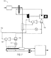
- FIG. 7 illustrates a schematic diagram of a cooling system 700 having two ejectors and two expansion valves to cool main and recirculation streams.
- System 700 includes a first cooling loop 702 having a suction accumulator, expansion valve, and ejector as previously described.
- System 700 operates in similar to fashion as system 600 of Figure 6 , and may also incorporate disclosed elements of other systems, as well.
- system 700 includes a separate cooling loop 704 that includes an ejector 706 and a second suction accumulator 708, as well as a second expansion valve 710. In such fashion the separate loops 702, 704 are separately throttled by their respective suction accumulators, thereby providing additional control, capacity, and flow options.
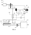
- FIG. 8 illustrates a system 800 that provides two separate cooling systems for aircraft cooling, according to one example. Both systems are sized to provide, in one example, the same capacity as one cooling system would be sized for. However, if one system fails, the second may be available for cooling duty. That is, system 800 includes a first cooling circuit 802, and a second cooling circuit 804, that are each generally thermodynamically separate from one another. Each cooling system 802, 804 includes, in the example shown, two ejectors, two evaporators, and two liquid separators (but in one example, not shown, may include only one liquid separator that is common to each). Pressurized air 806 is passed into first and second gas coolers or heat exchangers 808, 810, which are each cooled by RAM or other coolant as described.
- Each circuit includes a respective expander/compressor 812, 814, which is throttled by a respective ejector 816, 818.
- Each circuit 802, 804 includes two expansion valves or devices, and each includes a respective second evaporator 820, 822 to provide additional cooling which may likewise be used to provide coolant to the other circuit.
- system 800 may incorporate exemplary elements disclosed herein in other systems, as well.
- Each cooling circuit may cool pressurized air in a first evaporator and the re-circulating air in a second evaporator.
- one cooling circuit may cool pressurized air in two first evaporators and the other circuit may cool the re-circulating air in two second evaporators.
- a cooling system comprising: a first heat exchanger for cooling a refrigerant; an expander configured to receive the refrigerant from the first heat exchanger; at least one compressor configured to compress the refrigerant; an ejector configured to receive the refrigerant from the expander as a motive stream that evacuates and compresses the refrigerant from an evaporator; a liquid separator coupled to an output of the ejector and configured to provide liquid refrigerant to an evaporator loop and vapor refrigerant to the at least one compressor; and the evaporator loop comprising: an expansion device positioned to expand the liquid refrigerant from the liquid separator; and the evaporator configured to receive the refrigerant from the expansion device, heat the refrigerant from a heat load, and pass the refrigerant to the ejector.
- a method of cooling comprising: cooling a refrigerant in a first heat exchanger; receiving the refrigerant from the first heat exchanger in an expander; compressing the refrigerant in at least one compressor; receiving the refrigerant from the expander in an ejector that is configured to provide a motive stream that evacuates and compresses the refrigerant from an evaporator; providing liquid refrigerant to an evaporator loop and vapor refrigerant to the at least one compressor from a liquid separator that is coupled to an output of the ejector; and the evaporator loop comprising: an expansion device positioned to expand the liquid refrigerant from the liquid separator; and the evaporator configured to receive the refrigerant from the expansion device, heat the refrigerant from a heat load, and pass the refrigerant to the ejector.
- an aircraft cooling system comprising: a first gas cooler for cooling a refrigerant using air passing through the aircraft; a turbine configured to receive the refrigerant from the first gas cooler; at least one compressor configured to compress the refrigerant; an ejector configured to receive the refrigerant from the turbine as a stream that evacuates and compresses the refrigerant from an evaporator; a liquid separator coupled to an output of the ejector and configured to provide: liquid refrigerant to an evaporator loop; and vapor refrigerant to the at least one compressor; and the evaporator loop comprising: an expansion valve positioned to expand the liquid refrigerant from the liquid separator; and the evaporator configured to receive the refrigerant from the expansion valve, heat the refrigerant from a heat load, and pass the refrigerant to the ejector.
- the expander may be coupled to the at least one compressor via a shaft to provide power to the at least one compressor from the expander.
- the cooling system may comprise an expansion device positioned to receive refrigerant from the expander and pass the refrigerant to the ejector as the motive stream.
- the at least one compressor may comprise a first compressor configured to compress the refrigerant to a first pressure, and a second compressor configured to compress the refrigerant to a second pressure that is greater than the first pressure, the system further comprising: a shaft coupled to the first and second compressors, and to the expander, to provide power thereto from the expander; and a second heat exchanger for cooling the refrigerant from the first compressor, and passing the refrigerant to the second compressor.
- At least one of the first and second heat exchangers may be configured to receive air passing into an aircraft for cooling the refrigerant.
- the cooling system may comprise a recuperative heat exchanger positioned between at least inlets to each of the first and second compressors.
- the at least one compressor may comprise a first compressor configured to compress the refrigerant to a first pressure, and a second compressor configured to compress the refrigerant to a second pressure that is greater than the first pressure, the system further comprising: a shaft coupled to the one of the first and second compressors and to the expander, to provide power thereto from the expander; a second heat exchanger for cooling the refrigerant from the first compressor, and passing the refrigerant to the second compressor; a motor coupled to the other compressor; and a check valve coupled between an outlet of the second heat exchanger and an outlet of the second compressor.
- the cooling system may comprise a second evaporator loop comprising: a second expansion device positioned to expand the liquid refrigerant from the liquid separator; a second evaporator configured to receive the refrigerant from the second expansion device, heat the refrigerant from a second heat load, and pass the refrigerant to the ejector; and a mixer positioned to receive: recirculating air from within an aircraft that provides the heat load; and pressurized air that passes through the second evaporator that provides the second heat load; wherein the mixer is configured to mix the recirculating air and the pressurized air and provide cooling within the aircraft.
- the method may comprise providing power to the at least one compressor from the expander, wherein the expander is coupled to the at least one compressor via a shaft.
- the method may comprise receiving the refrigerant from the expander and passing the refrigerant to the ejector as the motive stream from an expansion device.
- the at least one compressor may comprise a first compressor that compresses the refrigerant to a first pressure, and a second compressor that compresses the refrigerant to a second pressure that is greater than the first pressure, the method further comprising: providing power to the first and second compressors via a shaft that is coupled to the expander; cooling the refrigerant from the first compressor in a second heat exchanger, and passing the refrigerant to the second compressor.
- the method may comprise receiving air passing into an aircraft and into at least one of the first and second heat exchangers for cooling the refrigerant.
- the method may comprise a recuperative heat exchanger positioned between at least inlets to each of the first and second compressors.
- the at least one compressor may comprise a first compressor that compresses the refrigerant to a first pressure, and a second compressor that compresses the refrigerant to a second pressure that is greater than the first pressure, the method further comprising: providing power to one of the first and second compressors from the expander via a shaft; cooling the refrigerant from the first compressor in a second heat exchanger, and passing the refrigerant to the second compressor; and providing power to the other compressor via a motor.
- the method may comprise a second evaporator loop comprising: a second expansion device positioned to expand the liquid refrigerant from the liquid separator; a second evaporator configured to receive the refrigerant from the second expansion device, heat the refrigerant from a second heat load, and pass the refrigerant to the ejector; and a mixer positioned to receive: recirculating air from within an aircraft that provides the heat load; and pressurized air that passes through the second evaporator that provides the second heat load; wherein the mixer mixes the recirculating air and the pressurized air and provides cooling within the aircraft.
- the turbine may be coupled to the at least one compressor via a shaft to provide power to the at least one compressor from the turbine.
- the aircraft cooling system may comprise an expansion device positioned to receive refrigerant from the turbine and pass the refrigerant to the ejector as the stream.
- the at least one compressor may comprises a first compressor configured to compress the refrigerant to a first pressure, and a second compressor configured to compress the refrigerant to a second pressure that is greater than the first pressure, the system further comprising: a shaft coupled to the first and second compressors, and to the turbine, to provide power thereto from the turbine; and a second heat exchanger for cooling the refrigerant from the first compressor, and passing the refrigerant to the second compressor.
Landscapes
- Engineering & Computer Science (AREA)
- Mechanical Engineering (AREA)
- Physics & Mathematics (AREA)
- Thermal Sciences (AREA)
- General Engineering & Computer Science (AREA)
- Chemical & Material Sciences (AREA)
- Combustion & Propulsion (AREA)
- Aviation & Aerospace Engineering (AREA)
- Separation By Low-Temperature Treatments (AREA)
- Heat-Exchange Devices With Radiators And Conduit Assemblies (AREA)
Abstract
Description
- An improved system and method of operating a cooling system in an aerospace application is disclosed, and more particularly, an improved system and method of cooling in a trans-critical operation.
- It has become increasingly desirable to improve cooling systems in aerospace applications. Typically, cooling systems provide air conditioning, refrigeration and freezer services, and the like for commercial and other aerospace systems. In general, various known options are available for providing cooling, but such options have drawbacks that limit the design options for aerospace applications.
- To accommodate the wide range of possible ambient operating conditions of the aircraft, cooling systems for aerospace applications often use a gas-based system. That is, typical cooling systems include a relatively bulky and low efficiency gas-based system in order to cover the range of conditions that can be experienced during aircraft operation.
- Some known systems provide a refrigerant that is cooled in an aircraft and passes through an expander and an expansion valve, to an expansion pressure that occurs in the expansion valve. The turbine, in one known system, expands refrigerant from a high pressure to a pressure that is above the dome, and additional expansion occurs in the expansion valve. Effectively, the system is throttled using the expansion valve. However, such operation can result in significant throttling losses and a reduced coefficient of performance (COP).
- Thus, there is a need to improve cooling in aircraft.
- According to the present disclosure, there is provided a cooling system and a method of cooling, as set forth in the appended claims.
- While the claims are not limited to a specific illustration, an appreciation of the various aspects is best gained through a discussion of various examples thereof. Referring now to the drawings, exemplary illustrations are shown in detail. Although the drawings represent the illustrations, the drawings are not necessarily to scale and certain features may be exaggerated to better illustrate and explain an innovative aspect of an example. Further, the exemplary illustrations described herein are not intended to be exhaustive or otherwise limiting or restricted to the precise form and configuration shown in the drawings and disclosed in the following detailed description. Exemplary illustrations are described in detail by referring to the drawings as follows:
-
Figure 1 is an illustration of a gas turbine engine employed in an aircraft and employing the improvements described herein; -
Figure 2 is an example of a cooling system having one compressor, and an ejector that provides a throttling function; -
Figure 3 is an example of a cooling system having two compressors; -
Figure 4 is an example of a cooling system having two compressors, and a recuperative heat exchanger; -
Figure 5 is an example of a cooling system having two compressors operated independent of one another; -
Figure 6 is an example of a cooling system having two evaporators and two expansion valves to cool main and recirculation streams; -
Figure 7 illustrates an example of a schematic diagram of acooling system 700 having two ejectors and two expansion valves to cool main and recirculation streams; and -
Figure 8 illustrates an example of a cooling system providing redundancy and having two pressurized air systems. - An exemplary cooling system for an aircraft application is described herein, and various embodiments thereof. A cooling system includes a first heat exchanger for cooling a refrigerant, an expander configured to receive the refrigerant from the first heat exchanger at least one compressor configured to compress the refrigerant, an ejector configured to receive the refrigerant from the expander as a motive stream that evacuates and compresses the refrigerant from an evaporator, and a liquid separator coupled to an output of the ejector and configured to provide liquid refrigerant to an evaporator loop and vapor refrigerant to the at least one compressor. The evaporator loop includes an expansion device positioned to expand the liquid refrigerant from the liquid separator, and the evaporator configured to receive the refrigerant from the expansion device, heat the refrigerant from a heat load, and pass the refrigerant to the ejector.
- Another exemplary illustration includes a method of cooling that includes cooling a refrigerant in a first heat exchanger, receiving the refrigerant from the first heat exchanger in an expander, compressing the refrigerant in at least one compressor, receiving the refrigerant from the expander in an ejector that is configured to provide a motive stream that evacuates and compresses the refrigerant from an evaporator, and providing liquid refrigerant to an evaporator loop and vapor refrigerant to the at least one compressor from a liquid separator that is coupled to an output of the ejector. The evaporator loop includes an expansion device positioned to expand the liquid refrigerant from the liquid separator, and the evaporator configured to receive the refrigerant from the expansion device, heat the refrigerant from a heat load, and pass the refrigerant to the ejector.
-
Figure 1 illustrates a schematic diagram of agas turbine machine 10 that is a primary mover or thrust source for an aircraft, utilizing the improvements disclosed herein. Theturbine machine 10 includes aprimary compressor 12, acombustor 14 and aprimary turbine assembly 16. A fan 18 includes anosecone assembly 20,blade members 22 and afan casing 24. Theblade members 22 direct low pressure air to abypass flow path 26 and to the compressor intake 28, which in turn provides airflow tocompressor 12. Components ofturbine machine 10 and as illustrated inFigure 1 generally do not correspond to components of embodiments of the cooling system in subsequent figures. That is, components ofFigure 1 generally correspond to components of an aircraft engine, whereas components in the subsequent figures (i.e., turbine, compressor) are components used to the cooling systems described and are separate from the components ofturbine machine 10. -
Figure 2 illustrates a schematic diagram of acooling system 200.System 200 includes a refrigerant circuit that includes a heat exchanger orgas cooler 202 for cooling a refrigerant, an expander orturbine 204 that is configured to receive the refrigerant fromheat exchanger 202, and acompressor 206 configured to compress the refrigerant. Anejector 208 is configured to receive the refrigerant from expander 204 as a motive stream that evacuates and compresses the refrigerant from anevaporator 210. Aliquid separator 212 is coupled to anoutput 214 ofejector 208 and configured to provide liquid refrigerant to anevaporator loop 216, and provide vapor refrigerant tocompressor 206. Theevaporator loop 216 includes anexpansion device 218 positioned to expand the liquid refrigerant fromliquid separator 212, andevaporator 210 is configured to receive the refrigerant fromexpansion device 218, heat the refrigerant from aheat load 220, and pass the refrigerant toejector 208. - The
heat exchanger 202 is cooled by a cooling fluid and may operate as a condenser or a gas cooler. Cooling fluid states at the inlet to theheat exchanger 202 and thermal loads on theevaporator 210 define the operating conditions of thecooling system 200. Theheat exchanger 202 may be cooled by different fluids: air, fuel, RAM air,
hydrogenated polyalphaolefin (PAO), water, any secondary refrigerant, fan bypass air or any available appropriate engine stream, as examples. As such, heat is rejected fromsystem 200 via heatrejection heat exchanger 202, and the heat rejection rate is defined by parameters of state of the cooling fluid. Parameters of state of the cooling fluid depend on the application and the fluid itself. For instance, operating conditions of the aircraft may include low static ambient temperatures and low pressures that occur when the aircraft is at high altitude, while high static ambient temperatures and pressures may occur at low altitude or at conditions on a tarmac. These static ambient pressure and temperature, Mach number, and pressure and temperature on the ground define the parameters of RAM air entering the heat rejection exchanger. - In one example, expander 204 is designed as a two-phase expander which means that the leaving state is a two-phase mixture; however, expander 204 may operate in single phase processes and in a vapor area.
Expander 204 is coupled tocompressor 206 via arotational shaft 222. The power generated in theexpander 204 may not be sufficient to drivecompressor 204. Therefore,compressor 206 employs amotor 224 to compensate for insufficient power. - A heat source for
evaporator 220 is associated with objects to be cooled (power electronics, HVAC for cabins and passenger compartments, and other mission systems, as examples). Evaporator 210 may cool air in a flight deck, a passenger compartment, or electronics. Alternativelyevaporator 210 can cool any of those or all of those via a coolant, which could be PAO, water, a water glycol mixture, or any other secondary refrigerant. Objects to be cooled, such as electronic devices, may be mounted on cold plates, which has channels for boiling refrigerant to execute direct cooling by the refrigerant.System 200 may havemultiple condensers 202 using the same or different heat sinks. Also,system 200 may havemultiple evaporators 210 using the same or different heat sources and loads. - Suction
accumulator 212 provides charge management and is part of a capacity control strategy. When the system cooling capacity exceeds the demand, the non-evaporated refrigerant is stored insuction accumulator 212. In the case of a capacity shortage, the accumulated refrigerant evaporates and resumes operation. In one example,system 200 includes an expansion valve ordevice 226. As examples,expansion device 214 is an orifice, a thermal expansion valve, an electronic expansion valve, a capillary tube or any other device providing isenthalpic expansion. In another example,system 200 includes arecuperative heat exchanger 228 for extracting heat from refrigerant passing fromsuction accumulator 212 tocompressor 206 via expanded refrigerant fromexpander 204. - CO2 (carbon dioxide), which enables trans-critical operation by spanning the temperature range from the hot end of
system 200 and atheat exchanger 202, to cold end inevaporator 210, is therefore a refrigerant of choice for use withsystem 200. It will be appreciated that another could be employed. If there is a need to elevate the critical point and extend the two phase region in order to improve the overall system performance a CO2 based mixture (such as CO2 and propane) may be selected as a refrigerant. As such, CO2 serves as a refrigerant that spans the range of operating conditions that may be experienced as changing ambient conditions of, for instance, the aircraft. Exiting the heat rejection exchanger CO2 is a gas when the temperature and pressure are above critical and is a liquid when the temperature and pressure are below critical. -
Figure 3 illustrates a schematic diagram of acooling system 300.System 300 includes an expander orturbine 302 that is coupled to a two-stage compression that includes afirst compressor 304 and asecond compressor 306.Expander 302 andcompressors shaft 308. Amotor 310 is coupled toshaft 308 to provide or augment power toshaft 308 in lieu of or in addition to power extracted fromexpander 302.System 300 includes a heat exchanger or gas cooler 312 that receives refrigerant fromcompressor 306 in a second stage of compression. Aheat exchanger 314 receives refrigerant in a first stage of compression fromcompressor 304.Compressor 304 compresses refrigerant to a first pressure, rejects heat to acoolant stream 316, and passes the refrigerant tocompressor 306.Compressor 306 compresses the refrigerant to a pressure that is greater than that ofcompressor 304, which is then cooled inheat exchanger 312 via acoolant stream 318. Thus, a two-stage compression is implemented having generally an improved coefficient of performance (COP) over known single stage systems. -
System 300 includes anevaporator loop 320 that includes anexpansion device 322 positioned to expand the liquid refrigerant from aliquid separator 324, and anevaporator 326 is configured to receive the refrigerant fromexpansion device 326, heat the refrigerant from aheat load 328, and pass the refrigerant to anejector 330.Ejector 330 is configured to receive the refrigerant fromexpander 302 as a motive stream that evacuates and compresses the refrigerant fromevaporator 326. In one example,system 300 includes arecuperative heat exchanger 332 that exchanges heat from the refrigerant stream entering the compressor and the stream exiting theheat exchanger 314, providing improved system efficiency. - In operation,
system 300 operates in fashions similar to that described forsystem 200 ofFigure 2 . However, two-stage compression provides additional compression capability and interstage cooling, which is throttled byejector 330. Theheat exchangers heat exchangers heat exchangers -
Figure 4 illustrates a schematic diagram of acooling system 400.System 400, comparable to the operation ofsystems gas coolers 402, a two-stage compressor/shaft 404 having an expander orturbine 406, and an evaporator loop 408.System 400 includes arecuperative heat exchanger 410 that provides cooling to refrigerant streams entering each compressor of two-stage compressor/shaft 404, by using the cooling effect of refrigerant as it exitsturbine 406. Anejector 412 is configured to receive the refrigerant fromexpander 406 as a motive stream that evacuates and compresses the refrigerant from the evaporator in evaporator loop 408. -
Figure 5 illustrates a schematic diagram of acooling system 500.System 500, comparable to the operation ofsystems gas coolers 502, and a compressor/expander 504 having an expander orturbine 506, and anevaporator loop 508. Compressor/expander 504 includes acompressor 510 that is driven byturbine 506. Anothercompressor 512 is included as a first stage compressor operates independent ofcompressor 510.Compressor 512 compresses refrigerant generally to a pressure that is lower than that ofcompressor 512. However, acheck valve 514 ensures that back-flow does not occur from refrigerant exitingcompressor 510.Compressor 512 includes a separate motor orindependent power source 516. Thus, in contrast tosystems system 500 includes independent operation of eachcompressor system 500 as described with other systems herein. In one example the compressor/expander 504 may have thecompressor 510 provided such that thecompressor 512 is driven by a motor or any other available prime mover. -
Figure 6 illustrates a schematic diagram of acooling system 600 having two evaporators and two expansion valves to cool main and recirculation streams. A compressor/expander 602 (which may include a motor 604) includes anejector 606 that is configured to receive refrigerant from an expander orturbine 608 as a motive stream that evacuates and compresses the refrigerant from anevaporator 610 in anevaporator loop 612. A recirculatingair stream 614 receives air that is moved by afan 616 and thus provides cooling toelements 618 of an aircraft that include, as examples, a flight deck, a cabin, electronics, and avionics. Air is provided from apressurized air source 618 that passes air to amixer 620, which also receives recirculation air passing fromevaporator 610. In one example,system 600 includes asecond cooling loop 622 that provides cooling to anevaporator 610 andevaporator 624. Eachloop valve suction accumulator 630 that receives refrigerant fromejector 606. - As such, in operation air from
pressurized source 618 is cooled inheat exchanger 624 andrecirculation air 614 is cooled inevaporator 610, mixed inmixer 620, and provided cooling toelements 618 for cooling of the aircraft. Refrigerant flow is expanded inejector 606 and passed to suction accumulator, for vapor refrigerant to pass to the compressor and for liquid refrigerant to pass toexpansion devices System 600 also may incorporate two stage compression, recuperative heat exchangers, and other elements of other disclosed systems as well. -
Figure 7 illustrates a schematic diagram of acooling system 700 having two ejectors and two expansion valves to cool main and recirculation streams.System 700 includes afirst cooling loop 702 having a suction accumulator, expansion valve, and ejector as previously described.System 700 operates in similar to fashion assystem 600 ofFigure 6 , and may also incorporate disclosed elements of other systems, as well. However,system 700 includes aseparate cooling loop 704 that includes anejector 706 and asecond suction accumulator 708, as well as asecond expansion valve 710. In such fashion theseparate loops -
Figure 8 illustrates asystem 800 that provides two separate cooling systems for aircraft cooling, according to one example. Both systems are sized to provide, in one example, the same capacity as one cooling system would be sized for. However, if one system fails, the second may be available for cooling duty. That is,system 800 includes afirst cooling circuit 802, and asecond cooling circuit 804, that are each generally thermodynamically separate from one another. Eachcooling system Pressurized air 806 is passed into first and second gas coolers orheat exchangers compressor respective ejector circuit second evaporator system 800 may incorporate exemplary elements disclosed herein in other systems, as well. Each cooling circuit may cool pressurized air in a first evaporator and the re-circulating air in a second evaporator. Optionally, one cooling circuit may cool pressurized air in two first evaporators and the other circuit may cool the re-circulating air in two second evaporators. - According to a first aspect, there is provided a cooling system, comprising: a first heat exchanger for cooling a refrigerant; an expander configured to receive the refrigerant from the first heat exchanger; at least one compressor configured to compress the refrigerant; an ejector configured to receive the refrigerant from the expander as a motive stream that evacuates and compresses the refrigerant from an evaporator; a liquid separator coupled to an output of the ejector and configured to provide liquid refrigerant to an evaporator loop and vapor refrigerant to the at least one compressor; and the evaporator loop comprising: an expansion device positioned to expand the liquid refrigerant from the liquid separator; and the evaporator configured to receive the refrigerant from the expansion device, heat the refrigerant from a heat load, and pass the refrigerant to the ejector.
- According to a second aspect, there is provided a method of cooling, comprising: cooling a refrigerant in a first heat exchanger; receiving the refrigerant from the first heat exchanger in an expander; compressing the refrigerant in at least one compressor; receiving the refrigerant from the expander in an ejector that is configured to provide a motive stream that evacuates and compresses the refrigerant from an evaporator; providing liquid refrigerant to an evaporator loop and vapor refrigerant to the at least one compressor from a liquid separator that is coupled to an output of the ejector; and the evaporator loop comprising: an expansion device positioned to expand the liquid refrigerant from the liquid separator; and the evaporator configured to receive the refrigerant from the expansion device, heat the refrigerant from a heat load, and pass the refrigerant to the ejector.
- According to a further aspect, there is provided an aircraft cooling system, comprising: a first gas cooler for cooling a refrigerant using air passing through the aircraft; a turbine configured to receive the refrigerant from the first gas cooler; at least one compressor configured to compress the refrigerant; an ejector configured to receive the refrigerant from the turbine as a stream that evacuates and compresses the refrigerant from an evaporator; a liquid separator coupled to an output of the ejector and configured to provide: liquid refrigerant to an evaporator loop; and vapor refrigerant to the at least one compressor; and the evaporator loop comprising: an expansion valve positioned to expand the liquid refrigerant from the liquid separator; and the evaporator configured to receive the refrigerant from the expansion valve, heat the refrigerant from a heat load, and pass the refrigerant to the ejector.
- The expander may be coupled to the at least one compressor via a shaft to provide power to the at least one compressor from the expander.
- The cooling system may comprise an expansion device positioned to receive refrigerant from the expander and pass the refrigerant to the ejector as the motive stream.
- The at least one compressor may comprise a first compressor configured to compress the refrigerant to a first pressure, and a second compressor configured to compress the refrigerant to a second pressure that is greater than the first pressure, the system further comprising: a shaft coupled to the first and second compressors, and to the expander, to provide power thereto from the expander; and a second heat exchanger for cooling the refrigerant from the first compressor, and passing the refrigerant to the second compressor.
- At least one of the first and second heat exchangers may be configured to receive air passing into an aircraft for cooling the refrigerant.
- The cooling system may comprise a recuperative heat exchanger positioned between at least inlets to each of the first and second compressors.
- The at least one compressor may comprise a first compressor configured to compress the refrigerant to a first pressure, and a second compressor configured to compress the refrigerant to a second pressure that is greater than the first pressure, the system further comprising: a shaft coupled to the one of the first and second compressors and to the expander, to provide power thereto from the expander; a second heat exchanger for cooling the refrigerant from the first compressor, and passing the refrigerant to the second compressor; a motor coupled to the other compressor; and a check valve coupled between an outlet of the second heat exchanger and an outlet of the second compressor.
- The cooling system may comprise a second evaporator loop comprising: a second expansion device positioned to expand the liquid refrigerant from the liquid separator; a second evaporator configured to receive the refrigerant from the second expansion device, heat the refrigerant from a second heat load, and pass the refrigerant to the ejector; and a mixer positioned to receive: recirculating air from within an aircraft that provides the heat load; and pressurized air that passes through the second evaporator that provides the second heat load; wherein the mixer is configured to mix the recirculating air and the pressurized air and provide cooling within the aircraft.
- The method may comprise providing power to the at least one compressor from the expander, wherein the expander is coupled to the at least one compressor via a shaft.
- The method may comprise receiving the refrigerant from the expander and passing the refrigerant to the ejector as the motive stream from an expansion device.
- The at least one compressor may comprise a first compressor that compresses the refrigerant to a first pressure, and a second compressor that compresses the refrigerant to a second pressure that is greater than the first pressure, the method further comprising: providing power to the first and second compressors via a shaft that is coupled to the expander; cooling the refrigerant from the first compressor in a second heat exchanger, and passing the refrigerant to the second compressor.
- The method may comprise receiving air passing into an aircraft and into at least one of the first and second heat exchangers for cooling the refrigerant.
- The method may comprise a recuperative heat exchanger positioned between at least inlets to each of the first and second compressors.
- The at least one compressor may comprise a first compressor that compresses the refrigerant to a first pressure, and a second compressor that compresses the refrigerant to a second pressure that is greater than the first pressure, the method further comprising: providing power to one of the first and second compressors from the expander via a shaft; cooling the refrigerant from the first compressor in a second heat exchanger, and passing the refrigerant to the second compressor; and providing power to the other compressor via a motor.
- The method may comprise a second evaporator loop comprising: a second expansion device positioned to expand the liquid refrigerant from the liquid separator; a second evaporator configured to receive the refrigerant from the second expansion device, heat the refrigerant from a second heat load, and pass the refrigerant to the ejector; and a mixer positioned to receive: recirculating air from within an aircraft that provides the heat load; and pressurized air that passes through the second evaporator that provides the second heat load; wherein the mixer mixes the recirculating air and the pressurized air and provides cooling within the aircraft.
- The turbine may be coupled to the at least one compressor via a shaft to provide power to the at least one compressor from the turbine.
- The aircraft cooling system may comprise an expansion device positioned to receive refrigerant from the turbine and pass the refrigerant to the ejector as the stream.
- The at least one compressor may comprises a first compressor configured to compress the refrigerant to a first pressure, and a second compressor configured to compress the refrigerant to a second pressure that is greater than the first pressure, the system further comprising: a shaft coupled to the first and second compressors, and to the turbine, to provide power thereto from the turbine; and a second heat exchanger for cooling the refrigerant from the first compressor, and passing the refrigerant to the second compressor.
- All terms used in the claims are intended to be given their broadest reasonable constructions and their ordinary meanings as understood by those knowledgeable in the technologies described herein unless an explicit indication to the contrary in made herein. In particular, use of the singular articles such as "a," "the," "said," etc. should be read to recite one or more of the indicated elements unless a claim recites an explicit limitation to the contrary.
Claims (15)
- A cooling system (200), comprising:a first heat exchanger (202) for cooling a refrigerant;an expander (204) configured to receive the refrigerant from the first heat exchanger (202);at least one compressor (206) configured to compress the refrigerant;an ejector (208) configured to receive the refrigerant from the expander (204) as a motive stream that evacuates and compresses the refrigerant from an evaporator (210);a liquid separator (210) coupled to an output of the ejector (208) and configured to provide liquid refrigerant to an evaporator loop (216) and vapor refrigerant to the at least one compressor (206); andthe evaporator loop (216) comprising:an expansion device (218) positioned to expand the liquid refrigerant from the liquid separator (212); andthe evaporator (210) configured to receive the refrigerant from the expansion device (218), heat the refrigerant from a heat load (220), and pass the refrigerant to the ejector (208).
- The cooling system (200) according to claim 1, wherein the expander (204) is coupled to the at least one compressor (206) via a shaft (222) to provide power to the at least one compressor (206) from the expander (204).
- The cooling system (200) according to any one of claims 1 or 2, comprising an expansion device (226) positioned to receive refrigerant from the expander (204) and pass the refrigerant to the ejector (208) as the motive stream.
- The cooling system (200) according to any one of claims 1, 2 or 3, wherein the at least one compressor (206) comprises a first compressor (304) configured to compress the refrigerant to a first pressure, and a second compressor (306) configured to compress the refrigerant to a second pressure that is greater than the first pressure, the system further comprising:a shaft (308) coupled to the first and second compressors (304, 306), and to the expander (302), to provide power thereto from the expander (302); anda second heat exchanger (314) for cooling the refrigerant from the first compressor (304), and passing the refrigerant to the second compressor (306).
- The cooling system (200) according to claim 4, wherein at least one of the first and second heat exchangers (314, 312) configured to receive air passing into an aircraft for cooling the refrigerant.
- The cooling system (200) according to any one of claims 4 or 5, comprising a recuperative heat exchanger (410) positioned between at least inlets to each of the first and second compressors (404).
- The cooling system (200) according to any preceding claim, wherein the at least one compressor comprises a first compressor (512) configured to compress the refrigerant to a first pressure, and a second compressor (510) configured to compress the refrigerant to a second pressure that is greater than the first pressure, the system further comprising:a shaft coupled to the one of the first and second compressors (512, 510) and to the expander (506), to provide power thereto from the expander (506);a second heat exchanger (502) for cooling the refrigerant from the first compressor (512), and passing the refrigerant to the second compressor (510);a motor (516) coupled to the other compressor (510); anda check valve (514) coupled between an outlet of the second heat exchanger (502) and an outlet of the second compressor (510).
- The cooling system (200) according to any preceding claim, comprising a second evaporator loop (704) comprising:a second expansion device (626) positioned to expand the liquid refrigerant from the liquid separator (630);a second evaporator (610) configured to receive the refrigerant from the second expansion device (626), heat the refrigerant from a second heat load (618), and pass the refrigerant to the ejector (606); anda mixer (620) positioned to receive:recirculating air (614) from within an aircraft that provides the heat load (618); andpressurized air (616) that passes through the second evaporator (610) that provides the second heat load (618);wherein the mixer (620) is configured to mix the recirculating air (614) and the pressurized air (616) and provide cooling within the aircraft.
- A method of cooling, comprising:cooling a refrigerant in a first heat exchanger (202);receiving the refrigerant from the first heat exchanger (202) in an expander (204);compressing the refrigerant in at least one compressor (206);receiving the refrigerant from the expander (204) in an ejector (208) that is configured to provide a motive stream that evacuates and compresses the refrigerant from an evaporator (210);providing liquid refrigerant to an evaporator loop (216) and vapor refrigerant to the at least one compressor (206) from a liquid separator (210) that is coupled to an output of the ejector (208); andthe evaporator loop (216) comprising:an expansion device (218) positioned to expand the liquid refrigerant from the liquid separator (210); andthe evaporator (210) configured to receive the refrigerant from the expansion device (218), heat the refrigerant from a heat load (220), and pass the refrigerant to the ejector (208).
- The method as claimed in claim 9, comprising receiving the refrigerant from the expander (204) and passing the refrigerant to the ejector (208) as the motive stream from an expansion device (226).
- The method according to any one of claims 9 or 10, wherein the at least one compressor (206) comprises a first compressor (304) that compresses the refrigerant to a first pressure, and a second compressor (306) that compresses the refrigerant to a second pressure that is greater than the first pressure, the method further comprising:providing power to the first and second compressors (304, 306) via a shaft (308) that is coupled to the expander (302);cooling the refrigerant from the first compressor (304) in a second heat exchanger (314), and passing the refrigerant to the second compressor (306).
- The method according to claim 11, comprising receiving air passing into an aircraft and into at least one of the first and second heat exchangers (304, 306) for cooling the refrigerant.
- The method according to any one of claims 11 or 12, comprising a recuperative heat exchanger (410) positioned between at least inlets to each of the first and second compressors (404).
- The method according to any one of claims 9 to 13, wherein the at least one compressor comprises a first compressor (512) that compresses the refrigerant to a first pressure, and a second compressor (510) that compresses the refrigerant to a second pressure that is greater than the first pressure, the method further comprising:providing power to one of the first and second compressors (512, 510) from the expander (506) via a shaft;cooling the refrigerant from the first compressor (512) in a second heat exchanger (502), and passing the refrigerant to the second compressor (510); andproviding power to the other compressor (510) via a motor (516).
- The method according to any one of claims 9 to 14, comprising a second evaporator loop (704) comprising:a second expansion device (626) positioned to expand the liquid refrigerant from the liquid separator (630);a second evaporator (610) configured to receive the refrigerant from the second expansion device (626), heat the refrigerant from a second heat load (618), and pass the refrigerant to the ejector (606); anda mixer (620) positioned to receive:recirculating air (614) from within an aircraft that provides the heat load (618); andpressurized air (616) that passes through the second evaporator (610) that provides the second heat load (618);wherein the mixer (620) mixes the recirculating air (614) and the pressurized air (616) and provides cooling within the aircraft.
Applications Claiming Priority (1)
| Application Number | Priority Date | Filing Date | Title |
|---|---|---|---|
| US201361921689P | 2013-12-30 | 2013-12-30 |
Publications (2)
| Publication Number | Publication Date |
|---|---|
| EP2889558A1 true EP2889558A1 (en) | 2015-07-01 |
| EP2889558B1 EP2889558B1 (en) | 2019-05-08 |
Family
ID=52347111
Family Applications (1)
| Application Number | Title | Priority Date | Filing Date |
|---|---|---|---|
| EP14199985.4A Active EP2889558B1 (en) | 2013-12-30 | 2014-12-23 | Cooling system with expander and ejector |
Country Status (2)
| Country | Link |
|---|---|
| US (1) | US10773818B2 (en) |
| EP (1) | EP2889558B1 (en) |
Cited By (1)
| Publication number | Priority date | Publication date | Assignee | Title |
|---|---|---|---|---|
| EP4606707A1 (en) * | 2024-02-23 | 2025-08-27 | Hamilton Sundstrand Corporation | Environmental control systems for an aircraft having a vapor compression system with a flash liquid expander turbine |
Families Citing this family (8)
| Publication number | Priority date | Publication date | Assignee | Title |
|---|---|---|---|---|
| FR3028291B1 (en) * | 2014-11-07 | 2019-04-12 | Airbus Helicopters | MOTOR ASSEMBLY PROVIDED WITH A TWO STAGE COOLING DEVICE FOR THE INTAKE AIR OF A TURBOMOTEUR |
| US11035595B2 (en) * | 2017-08-18 | 2021-06-15 | Rolls-Royce North American Technologies Inc. | Recuperated superheat return trans-critical vapor compression system |
| JP7094824B2 (en) * | 2018-08-10 | 2022-07-04 | 三菱重工サーマルシステムズ株式会社 | Refrigeration cycle system |
| AU2020327920B2 (en) * | 2019-08-13 | 2023-02-09 | Bechtel Energy Inc. | Systems and methods for improving the efficiency of open-cycle cascade-based liquified natural gas systems |
| US11173768B2 (en) | 2019-10-03 | 2021-11-16 | Hamilton Sundstrand Corporation | Aircraft multi-zone environmental control systems |
| US11148814B2 (en) | 2019-10-03 | 2021-10-19 | Hamilton Sundstrand Corporation | Refrigeration circuits, environmental control systems, and methods of controlling flow in refrigeration circuits |
| US11603795B2 (en) | 2019-10-23 | 2023-03-14 | Hamilton Sundstrand Corporation | Generator with air-cycle cooling |
| US11781817B2 (en) | 2021-06-22 | 2023-10-10 | Booz Allen Hamilton Inc. | Thermal management systems for extended operation |
Citations (6)
| Publication number | Priority date | Publication date | Assignee | Title |
|---|---|---|---|---|
| JPS5743172A (en) * | 1980-08-29 | 1982-03-11 | Hitachi Ltd | Refrigerating system |
| US20030005718A1 (en) * | 2001-07-05 | 2003-01-09 | Shimadzu Corporation | Aircraft air conditioner |
| JP2010133605A (en) * | 2008-12-03 | 2010-06-17 | Denso Corp | Ejector type refrigerating cycle |
| JP2010133606A (en) * | 2008-12-03 | 2010-06-17 | Denso Corp | Ejector type refrigerating cycle |
| EP2272757A2 (en) * | 2009-07-07 | 2011-01-12 | Hamilton Sundstrand Corporation | Transcritical fluid cooling for aerospace applications |
| US20110036118A1 (en) * | 2008-06-05 | 2011-02-17 | Mitsubishi Electric Corporation | Refrigeration cycle apparatus |
Family Cites Families (14)
| Publication number | Priority date | Publication date | Assignee | Title |
|---|---|---|---|---|
| US5467613A (en) * | 1994-04-05 | 1995-11-21 | Carrier Corporation | Two phase flow turbine |
| US7140197B2 (en) | 2002-02-22 | 2006-11-28 | Lalit Chordia | Means and apparatus for microrefrigeration |
| US6834514B2 (en) * | 2002-07-08 | 2004-12-28 | Denso Corporation | Ejector cycle |
| DK1498667T3 (en) | 2003-07-18 | 2010-08-16 | Star Refrigeration | Improved transcritical cooling cycle |
| DK1794510T3 (en) | 2004-08-09 | 2012-05-21 | Carrier Corp | CO2 refrigeration circuit with subcooling of the liquid refrigerant with the receiver flash gas and method for operating it |
| US7178362B2 (en) | 2005-01-24 | 2007-02-20 | Tecumseh Products Cormpany | Expansion device arrangement for vapor compression system |
| JP2008533431A (en) | 2005-03-18 | 2008-08-21 | キャリア・コマーシャル・リフリージレーション・インコーポレーテッド | Transcritical refrigeration with increased pressure relief valve |
| JP2007163016A (en) | 2005-12-13 | 2007-06-28 | Denso Corp | Ejector refrigeration cycle and control method of ejector refrigeration cycle |
| DE102007006993B4 (en) * | 2006-03-27 | 2019-12-05 | Hanon Systems | Carbon dioxide operated vehicle air conditioning system and method of operating the air conditioning system |
| FR2909439B1 (en) | 2006-12-01 | 2009-02-13 | Commissariat Energie Atomique | VAPOR COMPRESSION DEVICE AND METHOD OF REALIZING A TRANSCRITICAL CYCLE THEREFOR |
| US20110023533A1 (en) * | 2008-05-22 | 2011-02-03 | Mitsubishi Electric Corporation | Refrigerating cycle device |
| WO2010003590A2 (en) | 2008-07-07 | 2010-01-14 | Carrier Corporation | Refrigeration circuit |
| US20100313582A1 (en) | 2009-06-10 | 2010-12-16 | Oh Jongsik | High efficiency r744 refrigeration system and cycle |
| WO2012012496A2 (en) | 2010-07-23 | 2012-01-26 | Carrier Corporation | Ejector cycle refrigerant separator |
-
2014
- 2014-12-23 EP EP14199985.4A patent/EP2889558B1/en active Active
- 2014-12-29 US US14/583,931 patent/US10773818B2/en active Active
Patent Citations (6)
| Publication number | Priority date | Publication date | Assignee | Title |
|---|---|---|---|---|
| JPS5743172A (en) * | 1980-08-29 | 1982-03-11 | Hitachi Ltd | Refrigerating system |
| US20030005718A1 (en) * | 2001-07-05 | 2003-01-09 | Shimadzu Corporation | Aircraft air conditioner |
| US20110036118A1 (en) * | 2008-06-05 | 2011-02-17 | Mitsubishi Electric Corporation | Refrigeration cycle apparatus |
| JP2010133605A (en) * | 2008-12-03 | 2010-06-17 | Denso Corp | Ejector type refrigerating cycle |
| JP2010133606A (en) * | 2008-12-03 | 2010-06-17 | Denso Corp | Ejector type refrigerating cycle |
| EP2272757A2 (en) * | 2009-07-07 | 2011-01-12 | Hamilton Sundstrand Corporation | Transcritical fluid cooling for aerospace applications |
Cited By (2)
| Publication number | Priority date | Publication date | Assignee | Title |
|---|---|---|---|---|
| EP4606707A1 (en) * | 2024-02-23 | 2025-08-27 | Hamilton Sundstrand Corporation | Environmental control systems for an aircraft having a vapor compression system with a flash liquid expander turbine |
| US12583590B2 (en) | 2024-02-23 | 2026-03-24 | Hamilton Sundstrand Corporation | Environmental control systems for an aircraft having a vapor compression system with a flash liquid expander turbine |
Also Published As
| Publication number | Publication date |
|---|---|
| US20150191254A1 (en) | 2015-07-09 |
| US10773818B2 (en) | 2020-09-15 |
| EP2889558B1 (en) | 2019-05-08 |
Similar Documents
| Publication | Publication Date | Title |
|---|---|---|
| US10773818B2 (en) | Trans-critical CO2 cooling system for aerospace applications | |
| US9657969B2 (en) | Multi-evaporator trans-critical cooling systems | |
| US10288325B2 (en) | Trans-critical vapor cycle system with improved heat rejection | |
| EP2994385B1 (en) | Adaptive trans-critical co2 cooling systems for aerospace applications | |
| US9739200B2 (en) | Cooling systems for high mach applications | |
| US11448432B2 (en) | Adaptive trans-critical CO2 cooling system | |
| US9676484B2 (en) | Adaptive trans-critical carbon dioxide cooling systems | |
| EP2969756B1 (en) | Adaptive trans-critical co2 cooling systems for aerospace applications | |
| EP3295096B1 (en) | Ejector refrigeration circuit | |
| US10302342B2 (en) | Charge control system for trans-critical vapor cycle systems | |
| US9885283B2 (en) | Gas turbine engine driven by supercritical power generation system | |
| EP3051229B1 (en) | Thermal management system controlling dynamic and steady state thermal loads | |
| EP3054238B1 (en) | Charge control system for trans-critical vapor cycle systems | |
| EP3722707B1 (en) | Air conditioning system | |
| EP3800409B1 (en) | Refrigeration circuits, environmental control systems, and methods of controlling flow in refrigeration circuits | |
| EP3048388A1 (en) | Trans-critical vapor cycle system with improved heat rejection | |
| EP2896912B1 (en) | Aircraft cooling system |
Legal Events
| Date | Code | Title | Description |
|---|---|---|---|
| PUAI | Public reference made under article 153(3) epc to a published international application that has entered the european phase |
Free format text: ORIGINAL CODE: 0009012 |
|
| 17P | Request for examination filed |
Effective date: 20141223 |
|
| AK | Designated contracting states |
Kind code of ref document: A1 Designated state(s): AL AT BE BG CH CY CZ DE DK EE ES FI FR GB GR HR HU IE IS IT LI LT LU LV MC MK MT NL NO PL PT RO RS SE SI SK SM TR |
|
| AX | Request for extension of the european patent |
Extension state: BA ME |
|
| R17P | Request for examination filed (corrected) |
Effective date: 20151231 |
|
| RBV | Designated contracting states (corrected) |
Designated state(s): AL AT BE BG CH CY CZ DE DK EE ES FI FR GB GR HR HU IE IS IT LI LT LU LV MC MK MT NL NO PL PT RO RS SE SI SK SM TR |
|
| GRAP | Despatch of communication of intention to grant a patent |
Free format text: ORIGINAL CODE: EPIDOSNIGR1 |
|
| STAA | Information on the status of an ep patent application or granted ep patent |
Free format text: STATUS: GRANT OF PATENT IS INTENDED |
|
| INTG | Intention to grant announced |
Effective date: 20181128 |
|
| GRAS | Grant fee paid |
Free format text: ORIGINAL CODE: EPIDOSNIGR3 |
|
| GRAA | (expected) grant |
Free format text: ORIGINAL CODE: 0009210 |
|
| STAA | Information on the status of an ep patent application or granted ep patent |
Free format text: STATUS: THE PATENT HAS BEEN GRANTED |
|
| AK | Designated contracting states |
Kind code of ref document: B1 Designated state(s): AL AT BE BG CH CY CZ DE DK EE ES FI FR GB GR HR HU IE IS IT LI LT LU LV MC MK MT NL NO PL PT RO RS SE SI SK SM TR |
|
| REG | Reference to a national code |
Ref country code: GB Ref legal event code: FG4D |
|
| REG | Reference to a national code |
Ref country code: CH Ref legal event code: EP Ref country code: AT Ref legal event code: REF Ref document number: 1130782 Country of ref document: AT Kind code of ref document: T Effective date: 20190515 |
|
| REG | Reference to a national code |
Ref country code: DE Ref legal event code: R096 Ref document number: 602014046190 Country of ref document: DE Ref country code: IE Ref legal event code: FG4D |
|
| REG | Reference to a national code |
Ref country code: NL Ref legal event code: MP Effective date: 20190508 |
|
| REG | Reference to a national code |
Ref country code: LT Ref legal event code: MG4D |
|
| PG25 | Lapsed in a contracting state [announced via postgrant information from national office to epo] |
Ref country code: ES Free format text: LAPSE BECAUSE OF FAILURE TO SUBMIT A TRANSLATION OF THE DESCRIPTION OR TO PAY THE FEE WITHIN THE PRESCRIBED TIME-LIMIT Effective date: 20190508 Ref country code: LT Free format text: LAPSE BECAUSE OF FAILURE TO SUBMIT A TRANSLATION OF THE DESCRIPTION OR TO PAY THE FEE WITHIN THE PRESCRIBED TIME-LIMIT Effective date: 20190508 Ref country code: NL Free format text: LAPSE BECAUSE OF FAILURE TO SUBMIT A TRANSLATION OF THE DESCRIPTION OR TO PAY THE FEE WITHIN THE PRESCRIBED TIME-LIMIT Effective date: 20190508 Ref country code: FI Free format text: LAPSE BECAUSE OF FAILURE TO SUBMIT A TRANSLATION OF THE DESCRIPTION OR TO PAY THE FEE WITHIN THE PRESCRIBED TIME-LIMIT Effective date: 20190508 Ref country code: HR Free format text: LAPSE BECAUSE OF FAILURE TO SUBMIT A TRANSLATION OF THE DESCRIPTION OR TO PAY THE FEE WITHIN THE PRESCRIBED TIME-LIMIT Effective date: 20190508 Ref country code: SE Free format text: LAPSE BECAUSE OF FAILURE TO SUBMIT A TRANSLATION OF THE DESCRIPTION OR TO PAY THE FEE WITHIN THE PRESCRIBED TIME-LIMIT Effective date: 20190508 Ref country code: AL Free format text: LAPSE BECAUSE OF FAILURE TO SUBMIT A TRANSLATION OF THE DESCRIPTION OR TO PAY THE FEE WITHIN THE PRESCRIBED TIME-LIMIT Effective date: 20190508 Ref country code: PT Free format text: LAPSE BECAUSE OF FAILURE TO SUBMIT A TRANSLATION OF THE DESCRIPTION OR TO PAY THE FEE WITHIN THE PRESCRIBED TIME-LIMIT Effective date: 20190908 Ref country code: NO Free format text: LAPSE BECAUSE OF FAILURE TO SUBMIT A TRANSLATION OF THE DESCRIPTION OR TO PAY THE FEE WITHIN THE PRESCRIBED TIME-LIMIT Effective date: 20190808 |
|
| PG25 | Lapsed in a contracting state [announced via postgrant information from national office to epo] |
Ref country code: LV Free format text: LAPSE BECAUSE OF FAILURE TO SUBMIT A TRANSLATION OF THE DESCRIPTION OR TO PAY THE FEE WITHIN THE PRESCRIBED TIME-LIMIT Effective date: 20190508 Ref country code: GR Free format text: LAPSE BECAUSE OF FAILURE TO SUBMIT A TRANSLATION OF THE DESCRIPTION OR TO PAY THE FEE WITHIN THE PRESCRIBED TIME-LIMIT Effective date: 20190809 Ref country code: BG Free format text: LAPSE BECAUSE OF FAILURE TO SUBMIT A TRANSLATION OF THE DESCRIPTION OR TO PAY THE FEE WITHIN THE PRESCRIBED TIME-LIMIT Effective date: 20190808 Ref country code: RS Free format text: LAPSE BECAUSE OF FAILURE TO SUBMIT A TRANSLATION OF THE DESCRIPTION OR TO PAY THE FEE WITHIN THE PRESCRIBED TIME-LIMIT Effective date: 20190508 |
|
| REG | Reference to a national code |
Ref country code: AT Ref legal event code: MK05 Ref document number: 1130782 Country of ref document: AT Kind code of ref document: T Effective date: 20190508 |
|
| PG25 | Lapsed in a contracting state [announced via postgrant information from national office to epo] |
Ref country code: AT Free format text: LAPSE BECAUSE OF FAILURE TO SUBMIT A TRANSLATION OF THE DESCRIPTION OR TO PAY THE FEE WITHIN THE PRESCRIBED TIME-LIMIT Effective date: 20190508 Ref country code: CZ Free format text: LAPSE BECAUSE OF FAILURE TO SUBMIT A TRANSLATION OF THE DESCRIPTION OR TO PAY THE FEE WITHIN THE PRESCRIBED TIME-LIMIT Effective date: 20190508 Ref country code: SK Free format text: LAPSE BECAUSE OF FAILURE TO SUBMIT A TRANSLATION OF THE DESCRIPTION OR TO PAY THE FEE WITHIN THE PRESCRIBED TIME-LIMIT Effective date: 20190508 Ref country code: RO Free format text: LAPSE BECAUSE OF FAILURE TO SUBMIT A TRANSLATION OF THE DESCRIPTION OR TO PAY THE FEE WITHIN THE PRESCRIBED TIME-LIMIT Effective date: 20190508 Ref country code: EE Free format text: LAPSE BECAUSE OF FAILURE TO SUBMIT A TRANSLATION OF THE DESCRIPTION OR TO PAY THE FEE WITHIN THE PRESCRIBED TIME-LIMIT Effective date: 20190508 Ref country code: DK Free format text: LAPSE BECAUSE OF FAILURE TO SUBMIT A TRANSLATION OF THE DESCRIPTION OR TO PAY THE FEE WITHIN THE PRESCRIBED TIME-LIMIT Effective date: 20190508 |
|
| REG | Reference to a national code |
Ref country code: DE Ref legal event code: R097 Ref document number: 602014046190 Country of ref document: DE |
|
| PG25 | Lapsed in a contracting state [announced via postgrant information from national office to epo] |
Ref country code: SM Free format text: LAPSE BECAUSE OF FAILURE TO SUBMIT A TRANSLATION OF THE DESCRIPTION OR TO PAY THE FEE WITHIN THE PRESCRIBED TIME-LIMIT Effective date: 20190508 Ref country code: IT Free format text: LAPSE BECAUSE OF FAILURE TO SUBMIT A TRANSLATION OF THE DESCRIPTION OR TO PAY THE FEE WITHIN THE PRESCRIBED TIME-LIMIT Effective date: 20190508 |
|
| PLBE | No opposition filed within time limit |
Free format text: ORIGINAL CODE: 0009261 |
|
| STAA | Information on the status of an ep patent application or granted ep patent |
Free format text: STATUS: NO OPPOSITION FILED WITHIN TIME LIMIT |
|
| PG25 | Lapsed in a contracting state [announced via postgrant information from national office to epo] |
Ref country code: TR Free format text: LAPSE BECAUSE OF FAILURE TO SUBMIT A TRANSLATION OF THE DESCRIPTION OR TO PAY THE FEE WITHIN THE PRESCRIBED TIME-LIMIT Effective date: 20190508 |
|
| 26N | No opposition filed |
Effective date: 20200211 |
|
| PG25 | Lapsed in a contracting state [announced via postgrant information from national office to epo] |
Ref country code: PL Free format text: LAPSE BECAUSE OF FAILURE TO SUBMIT A TRANSLATION OF THE DESCRIPTION OR TO PAY THE FEE WITHIN THE PRESCRIBED TIME-LIMIT Effective date: 20190508 |
|
| PG25 | Lapsed in a contracting state [announced via postgrant information from national office to epo] |
Ref country code: SI Free format text: LAPSE BECAUSE OF FAILURE TO SUBMIT A TRANSLATION OF THE DESCRIPTION OR TO PAY THE FEE WITHIN THE PRESCRIBED TIME-LIMIT Effective date: 20190508 |
|
| REG | Reference to a national code |
Ref country code: CH Ref legal event code: PL |
|
| REG | Reference to a national code |
Ref country code: BE Ref legal event code: MM Effective date: 20191231 |
|
| PG25 | Lapsed in a contracting state [announced via postgrant information from national office to epo] |
Ref country code: MC Free format text: LAPSE BECAUSE OF FAILURE TO SUBMIT A TRANSLATION OF THE DESCRIPTION OR TO PAY THE FEE WITHIN THE PRESCRIBED TIME-LIMIT Effective date: 20190508 |
|
| GBPC | Gb: european patent ceased through non-payment of renewal fee |
Effective date: 20191223 |
|
| PG25 | Lapsed in a contracting state [announced via postgrant information from national office to epo] |
Ref country code: IE Free format text: LAPSE BECAUSE OF NON-PAYMENT OF DUE FEES Effective date: 20191223 Ref country code: LU Free format text: LAPSE BECAUSE OF NON-PAYMENT OF DUE FEES Effective date: 20191223 Ref country code: GB Free format text: LAPSE BECAUSE OF NON-PAYMENT OF DUE FEES Effective date: 20191223 |
|
| PG25 | Lapsed in a contracting state [announced via postgrant information from national office to epo] |
Ref country code: CH Free format text: LAPSE BECAUSE OF NON-PAYMENT OF DUE FEES Effective date: 20191231 Ref country code: LI Free format text: LAPSE BECAUSE OF NON-PAYMENT OF DUE FEES Effective date: 20191231 Ref country code: BE Free format text: LAPSE BECAUSE OF NON-PAYMENT OF DUE FEES Effective date: 20191231 |
|
| PG25 | Lapsed in a contracting state [announced via postgrant information from national office to epo] |
Ref country code: CY Free format text: LAPSE BECAUSE OF FAILURE TO SUBMIT A TRANSLATION OF THE DESCRIPTION OR TO PAY THE FEE WITHIN THE PRESCRIBED TIME-LIMIT Effective date: 20190508 |
|
| PG25 | Lapsed in a contracting state [announced via postgrant information from national office to epo] |
Ref country code: IS Free format text: LAPSE BECAUSE OF FAILURE TO SUBMIT A TRANSLATION OF THE DESCRIPTION OR TO PAY THE FEE WITHIN THE PRESCRIBED TIME-LIMIT Effective date: 20190908 |
|
| PG25 | Lapsed in a contracting state [announced via postgrant information from national office to epo] |
Ref country code: MT Free format text: LAPSE BECAUSE OF FAILURE TO SUBMIT A TRANSLATION OF THE DESCRIPTION OR TO PAY THE FEE WITHIN THE PRESCRIBED TIME-LIMIT Effective date: 20190508 Ref country code: HU Free format text: LAPSE BECAUSE OF FAILURE TO SUBMIT A TRANSLATION OF THE DESCRIPTION OR TO PAY THE FEE WITHIN THE PRESCRIBED TIME-LIMIT; INVALID AB INITIO Effective date: 20141223 |
|
| PG25 | Lapsed in a contracting state [announced via postgrant information from national office to epo] |
Ref country code: MK Free format text: LAPSE BECAUSE OF FAILURE TO SUBMIT A TRANSLATION OF THE DESCRIPTION OR TO PAY THE FEE WITHIN THE PRESCRIBED TIME-LIMIT Effective date: 20190508 |
|
| P01 | Opt-out of the competence of the unified patent court (upc) registered |
Effective date: 20230528 |
|
| PGFP | Annual fee paid to national office [announced via postgrant information from national office to epo] |
Ref country code: FR Payment date: 20251230 Year of fee payment: 12 |
|
| PGFP | Annual fee paid to national office [announced via postgrant information from national office to epo] |
Ref country code: DE Payment date: 20251229 Year of fee payment: 12 |