EP2889546A1 - Air conditioning management system - Google Patents
Air conditioning management system Download PDFInfo
- Publication number
- EP2889546A1 EP2889546A1 EP13813722.9A EP13813722A EP2889546A1 EP 2889546 A1 EP2889546 A1 EP 2889546A1 EP 13813722 A EP13813722 A EP 13813722A EP 2889546 A1 EP2889546 A1 EP 2889546A1
- Authority
- EP
- European Patent Office
- Prior art keywords
- air conditioning
- address
- section
- temporary
- conditioning units
- Prior art date
- Legal status (The legal status is an assumption and is not a legal conclusion. Google has not performed a legal analysis and makes no representation as to the accuracy of the status listed.)
- Granted
Links
Images







Classifications
-
- F—MECHANICAL ENGINEERING; LIGHTING; HEATING; WEAPONS; BLASTING
- F24—HEATING; RANGES; VENTILATING
- F24F—AIR-CONDITIONING; AIR-HUMIDIFICATION; VENTILATION; USE OF AIR CURRENTS FOR SCREENING
- F24F11/00—Control or safety arrangements
- F24F11/30—Control or safety arrangements for purposes related to the operation of the system, e.g. for safety or monitoring
-
- F—MECHANICAL ENGINEERING; LIGHTING; HEATING; WEAPONS; BLASTING
- F24—HEATING; RANGES; VENTILATING
- F24F—AIR-CONDITIONING; AIR-HUMIDIFICATION; VENTILATION; USE OF AIR CURRENTS FOR SCREENING
- F24F11/00—Control or safety arrangements
- F24F11/50—Control or safety arrangements characterised by user interfaces or communication
- F24F11/54—Control or safety arrangements characterised by user interfaces or communication using one central controller connected to several sub-controllers
-
- F—MECHANICAL ENGINEERING; LIGHTING; HEATING; WEAPONS; BLASTING
- F24—HEATING; RANGES; VENTILATING
- F24F—AIR-CONDITIONING; AIR-HUMIDIFICATION; VENTILATION; USE OF AIR CURRENTS FOR SCREENING
- F24F11/00—Control or safety arrangements
- F24F11/62—Control or safety arrangements characterised by the type of control or by internal processing, e.g. using fuzzy logic, adaptive control or estimation of values
-
- G—PHYSICS
- G05—CONTROLLING; REGULATING
- G05B—CONTROL OR REGULATING SYSTEMS IN GENERAL; FUNCTIONAL ELEMENTS OF SUCH SYSTEMS; MONITORING OR TESTING ARRANGEMENTS FOR SUCH SYSTEMS OR ELEMENTS
- G05B15/00—Systems controlled by a computer
- G05B15/02—Systems controlled by a computer electric
-
- F—MECHANICAL ENGINEERING; LIGHTING; HEATING; WEAPONS; BLASTING
- F24—HEATING; RANGES; VENTILATING
- F24F—AIR-CONDITIONING; AIR-HUMIDIFICATION; VENTILATION; USE OF AIR CURRENTS FOR SCREENING
- F24F11/00—Control or safety arrangements
- F24F11/50—Control or safety arrangements characterised by user interfaces or communication
- F24F11/56—Remote control
-
- G—PHYSICS
- G05—CONTROLLING; REGULATING
- G05B—CONTROL OR REGULATING SYSTEMS IN GENERAL; FUNCTIONAL ELEMENTS OF SUCH SYSTEMS; MONITORING OR TESTING ARRANGEMENTS FOR SUCH SYSTEMS OR ELEMENTS
- G05B2219/00—Program-control systems
- G05B2219/20—Pc systems
- G05B2219/26—Pc applications
- G05B2219/2614—HVAC, heating, ventillation, climate control
-
- G—PHYSICS
- G05—CONTROLLING; REGULATING
- G05B—CONTROL OR REGULATING SYSTEMS IN GENERAL; FUNCTIONAL ELEMENTS OF SUCH SYSTEMS; MONITORING OR TESTING ARRANGEMENTS FOR SUCH SYSTEMS OR ELEMENTS
- G05B2219/00—Program-control systems
- G05B2219/20—Pc systems
- G05B2219/26—Pc applications
- G05B2219/2642—Domotique, domestic, home control, automation, smart house
Definitions
- the present invention relates to an air conditioning management system.
- the serial number changes when the print substrate is replaced due to a breakage or the like and the order of the serial numbers of the plurality of air conditioning units changes due to this.
- the addresses which are set for each of the air conditioning units also change.
- the order of the serial numbers of the plurality of indoor units changes in a case where the indoor unit which is new is added and the addresses which are set for each of the indoor units also change to accompany this.
- a method of setting the addresses for each of the air conditioning units manually using an operating means such as a remote control unit is more preferable from the point that it is possible to set the addresses while visually confirming the set units.
- an operating means such as a remote control unit
- a technician who goes out and visits for setting the real addresses needs to goes out and visit again in order to set the addresses of the air conditioning units in locations where it is not possible to gain entry, and the burden and costs of work for introducing the system increase.
- the object of the present invention is to provide an air conditioning system where it is possible to reduce the burden and costs of work for introducing the system.
- An air conditioning management system manages a plurality of air conditioning units, which each have a unique physical address, using logical addresses and is provided with a local controller which collects driving information for each of the air conditioning units and an operating means for each of the air conditioning units with the operating means arranged in the vicinity of each of the air conditioning units.
- the local controller has a memory section, an information collecting section, and an associating section.
- the memory section stores identification information for each of the air conditioning units.
- the information collecting section collects the driving information for each of the air conditioning units.
- the associating section associates the driving information with the logical addresses.
- the identification information for each of the air conditioning units has a physical address section which contains the physical address, a real address section which contains a real address, and a temporary address section which contains a temporary address.
- the real address is set from the operating means. It is possible for the temporary address to be arbitrarily set without the operating means.
- the associating section uses the real address as the logical address in a case where the real address is set and uses the temporary address as the logical address in a case where the real address is not set.
- the plurality of air conditioning units include an outdoor unit and an indoor unit which communicate with each other using the physical address.
- the air conditioning system manages each of the air conditioning units using the logical addresses separately to the physical addresses. Then, the real address, which is set via the operating means which is a remote control unit or the like, is used as the logical address and the temporary address, which is able to be arbitrarily set without the operating means which is a remote control unit or the like, is used as the logical address in a case where the real address is not set. Due to this, it is possible to manage each of the air conditioning units using the temporary addresses even in a case where the location where the air conditioning units are disposed is off limits to entry during work for introducing the system due to any circumstances and it is not possible to set the real address using the operating means which is a remote control unit or the like. Accordingly, the burden and costs of work for introducing the system such as repeat visits by a technician are reduced.
- An air conditioning management system is the air conditioning management system according to the first aspect of the present invention where an offsite controller is further provided.
- the offsite controller is connected to the local controller via a communication network.
- the offsite controller has an information receiving section and an offsite management section.
- the information receiving section receives the driving information from the local controller.
- the offsite management section manages each of the air conditioning units using the logical addresses.
- An air conditioning management system is the air conditioning management system according to the first aspect or the second aspect of the present invention where each of the air conditioning units has a communication substrate.
- the physical address is determined based on the identification information of the communication substrate.
- the physical address is automatically determined based on the identification information of the communication substrate, work for setting the physical address, which is used in communication between the outdoor unit and the indoor unit, is not necessary.
- An air conditioning management system is the air conditioning management system according to any of the first aspect to the third aspect of the present invention where the real address and the temporary address are information with the same format.
- An air conditioning management system is the air conditioning management system according to any of the first aspect to the fourth aspect of the present invention where the real address has a predetermined initial value.
- the associating section uses the temporary address as the logical address in a case where the real address is the initial value.
- An air conditioning management system is the air conditioning management system according to any of the first aspect to the fifth aspect of the present invention where the local controller further has an address updating section.
- the address updating section updates only the physical address when the communication substrate is replaced.
- An air conditioning management system is the air conditioning management system according to any of the first aspect to the sixth aspect of the present invention where the local controller further has a first temporary address setting reception section which receives setting of the temporary addresses.
- An air conditioning management system is the air conditioning management system according to any of the first aspect to the seventh aspect of the present invention where a temporary address setting device is further provided.
- the temporary address setting device has a temporary address setting reception section.
- An air conditioning management system is the air conditioning management system according to the eighth aspect of the present invention where the temporary address setting device further has a temporary address setting section.
- the temporary address setting section sets the temporary addresses based on the physical addresses.
- the burden and costs of work for introducing the system are reduced.
- the burden and costs of management are reduced.
- Fig. 1 is a diagram illustrating an overall configuration of an air conditioning management system 100.
- the air conditioning management system 100 is a system for managing a plurality of air conditioning units 50 which are each disposed at a plurality of buildings 1a, 1b, and so on.
- the buildings 1a, 1b, and so on are in various areas.
- air conditioning systems 40a, 40b, and so on and local controllers 10a, 10b, and so on are disposed.
- An offsite controller 20 is arranged at an offsite management center 2 which is a distance from the buildings 1a, 1b, and so on.
- the local controllers 10a, 10b, and so on manage the air conditioning systems 40a, 40b, and so on in the buildings 1a, 1b, and so on where the local controllers 10a, 10b, and so on are arranged.
- the air conditioning systems 40a, 40b, and so on are configured from a plurality of the air conditioning units 50 (refer to Fig. 2 ).
- the offsite controller 20 is connected to the local controllers 10a, 10b, and so on via a communication network 4 such as the Internet.
- Fig. 2 is a diagram illustrating the configuration of the building 1a in further detail.
- the configurations of the buildings 1b and so on are the same as for the building 1a.
- a plurality of the air conditioning units 50 and the local controller 10a which is connected to the plurality of air conditioning units 50 using a dedicated air conditioning unit communication wiring 6, are disposed in the building 1a.
- a plurality of outdoor units 51a, 51b, and 51c (referred to below as outdoor units 51) and a plurality of indoor units 52a, 52b, 52c, 52d, 52e, 52f, 52g, 52h, and 52i (referred to below as indoor units 52) which are connected to the outdoor units 51 using the dedicated air conditioning unit communication wiring 6 are included in the plurality of air conditioning units 50.
- the local controller 10a is connected with each of the outdoor units 51 using the dedicated air conditioning unit communication wiring 6.
- a test driving work terminal 30 which is connected with the local controller 10a using a communication network 5 such as a LAN, is not a permanent fixture and is used by being carried in by a technician during a portion of test driving work for the air conditioning management system 100 at the building 1a.
- the test driving work terminal 30 is not represented in Fig. 1 .
- physical addresses 101a are used in controlling the air conditioning units 50 and logical addresses 105a are used separately to the physical addresses 101a in managing the air conditioning units 50. It is possible for a real address 103a and a temporary address 104a which will be described later to be set for each of the air conditioning units 50 and either of these addresses are used as the logical address 105a.
- Communication between the outdoor units 51 and the indoor units 52 which is performed in order to control compressors, fans, and the like uses the physical addresses 101a. That is, controlling of the outdoor units 51 and the indoor units 52 is performed using the physical addresses 101a when controlling while the outdoor units 51 and the indoor units 52 are communicating with each other. That is, the outdoor unit 51 identifies the plurality of indoor units 52, with which the outdoor unit 51 is connected, using the respective physical addresses 101a.
- the physical address 101a is an address which is given to each of the air conditioning units 50 based on serial numbers 102a of print substrates 51p and 52p (refer to Fig. 3 ) in each of the air conditioning units 50 and is data which is smaller in size than the serial numbers 102a of the print substrates 51p and 52p.
- the bandwidth of the dedicated air conditioning unit communication wiring 6 which connects between the air conditioning units 50 is very small and communication speed is faster when using the physical address 101 a than when using the serial numbers 102a of the print substrates 51p and 52p.
- each of the air conditioning units 50 is identified using the logical addresses 105a when managing each of the air conditioning units 50 such as when accumulating driving information for the air conditioning units 50 and detecting abnormalities by analyzing the driving information.
- the physical addresses 101a of each of the air conditioning units 50 where the print substrates 51p and 52p are replaced due to breakages as will be described later, automatically change to an address which is based on the ordering of the serial numbers 102a of the print substrates 51p and 52p which are new.
- the physical addresses 101a are automatically set and there is a possibility that the corresponding relationship between the physical addresses 101a and the air conditioning units 50 will change even with the air conditioning units 50 where the print substrates 51p and 52p are not replaced.
- the logical address 105a is set for each of the air conditioning units 50 separately to the physical address 101a and at least the corresponding relationship between the logical addresses 105a and the air conditioning units 50 where the print substrates 51p and 52p are not replaced does not change. In this manner, the burden and costs of management are reduced due to each of the air conditioning units 50 being identified and managed using the logical addresses 105a.
- the address which is used as the logical address 105a is the real address 103a or the temporary address 104a.
- the temporary address 104a is an address which is sets as an address which is temporary as a substitute in a case where access into the location where the air conditioning units 50 are disposed is not possible due to any circumstances and it is not possible to set the real address 103a using the remote control unit 43.
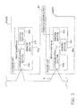
- the plurality of the air conditioning units 50 in the present embodiment include the outdoor units 51 and the indoor units 52.
- Fig. 3 is a block diagram which represents this configuration in further detail with the outdoor unit 51 and the indoor unit 52 out of the plurality of air conditioning units 50.
- the configurations of the outdoor unit 51 and the indoor unit 52 out of the plurality of air conditioning units 50 will be described below with reference to Fig. 3 .
- the outdoor unit 51 has a compressor, a heat exchanger, an expansion mechanism, a fan, and the like which are not shown in the diagrams and is disposed on the outside of the building 1a.
- the indoor units 52 has a fan, a heat exchanger, and the like which are not shown in the diagrams and is disposed inside each room in the building 1a.
- the outdoor unit 51 and the indoor unit 52 are connected using a refrigerant pipe which is not shown in the diagrams and configure a refrigerant circuit.
- various types of sensors which are not shown in the diagrams are attached to the outdoor unit 51 and the indoor unit 52.
- a room temperature sensor which detects the temperature of a room in which the indoor unit 52 is disposed is attached to the indoor unit 52.
- An outdoor temperature sensor which detects the outdoor temperature, a discharge temperature sensor which detects the discharge temperature which is the temperature of refrigerant at a discharge pipe in the compressor, a discharge pressure sensor which detects the discharge pressure which is the pressure of refrigerant at a discharge pipe in the compressor, a suction pressure sensor which detects the suction pressure which is the pressure of refrigerant at a suction pipe in the compressor, and the like are attached to the outdoor unit 51.
- the outdoor unit 51 and the indoor unit 52 respectively have the print substrates 51p and 52p.
- the print substrates 51p and 52p are substrates onto which an electrical circuit is printed and respectively have communication sections 51 a and 52a, control sections 51b and 52b, and memory sections 51c and 52c.
- the communication sections 51a and 52a are interfaces with regard to the dedicated air conditioning unit communication wiring 6, transmit a signal through the dedicated air conditioning unit communication wiring 6 in accordance with commands from the control sections 51b and 52b, receive signals from the dedicated air conditioning unit communication wiring 6, and send signals which represent this to the control sections 51b and 52b.
- control sections 51b and 52b control the actions of the outdoor unit 51 and the indoor unit 52 in accordance with control commands which are input from the manager of the building 1a via the local controller 10a and control commands which are input by a typical user in a room via the remote control unit 43, that is, the control sections 51b and 52b control the actions of each section such as the compressor which is included in the refrigerant circuit.
- control sections 51b and 52b transmit data which is related to the outdoor unit 51 or the indoor unit 52 to the local controller 10a via the communication sections 51a and 52a.
- the control sections 51b and 52b transmit values which are detected by the various types of sensors to the local controller 10a as the driving information in predetermined intervals (one minute in the present embodiment).
- the control sections 51b and 52b transmit machine numbers, the serial numbers 102a of the print substrates 51p and 52p, product classification codes, the physical addresses 101a and the real addresses 103a which will be described later, and the like to the local controller 10a via the communication sections 51a and 52a.
- the control sections 51b and 52b transmit control commands which are input directly, when the control commands are input via the remote control unit 43, to the local controller 10a via the communication sections 51a and 51b.
- the memory sections 51c and 52c are, for example, EEPROMs and store the unique serial numbers 102a of each of the print substrates 51p and 52p, product classification codes, machine numbers, the physical addresses 101a and the real addresses 103a, and the like.
- Fig. 4 is a block diagram illustrating a configuration of the local controller 10a.
- the configuration of the local controller 10a will be described below.
- the configurations of the local controllers10b and so on are the same as for the local controller 10a.
- the local controller 10a is disposed in the building 1a, for example, in a management room and manages the plurality of air conditioning units 50 which include the outdoor units 51 and the indoor units 52 described above which are also disposed in the building 1a.
- the local controller 10a detects abnormalities in the air conditioning units 50, receives inputting of a driving schedule of the air conditioning units 50, and controls driving of the air conditioning units 50 in accordance with the driving schedule.
- the local controller 10a is connected with the communication network 4 which is a wide-area communication network such as the Internet and is connected with the offsite controller 20 in the offsite management center 2 via the communication network 4.
- the local controller 10a is also connected to the communication network 5 which is a local communication network such as a LAN in the building 1a.
- the local controller 10a mainly has a network side communication section 11a, an air conditioning unit side communication section 11b, a control section 12, a memory section 13, an output section 14, and an input section 15.
- the network side communication section 11a is an interface with regard to a communication network where an Ethernet (registered trademark) or the like is used and it is possible for the local controller 10a to connect with communication networks such as the Internet or a LAN.
- Ethernet registered trademark
- the air conditioning unit side communication section 11b is an interface with regard to the dedicated air conditioning unit communication wiring 6 and is able to connect the local controller 10a with the dedicated air conditioning unit communication wiring 6.
- the control section 12 is mainly formed from a CPU and has an information collecting section 12a, an identification information constructing section 12b, an associating section 12c, a driving information transmitting section 12d, an abnormality detecting section 12e, a physical address setting section 12f, and a temporary address setting reception section 12g due to control programs for the local controller 10a being executed.
- the information collecting section 12a collects driving information 13b which is transmitted from each of the air conditioning units 50 in predetermined intervals (one minute in the present embodiment). In detail, when the air conditioning unit side communication section 11b receives the driving information 13b which is transmitted from each of the air conditioning units 50 and a signal for notifying this is received from the air conditioning unit side communication section 11b, the information collecting section 12a accumulates and stores the driving information 13b in the memory section 13.
- the identification information constructing section 12b constructs identification information 13a for each of the air conditioning units 50.
- the identification information 13a is information as shown in Fig. 5 and is information which is for individually identifying each of the air conditioning units 50.
- the identification information constructing section 12b first stores the identification information 13a, which is currently in the memory section 13, in the memory section 13 as old identification information. Next, the identification information constructing section 12b transmits a command so that various types of information which are for identifying are transmitted with regard to each of the air conditioning units 50 via the air conditioning unit side communication section 11b.
- Each of the air conditioning units 50 which receive this command transmits machine numbers, the serial numbers 102a of the print substrates 51p and 52p, product classification codes, the physical addresses 101a, the real addresses 103a, and the like to the local controller 10a.
- the identification information constructing section 12b stores this information in the memory section 13 as the identification information 13a.
- the identification information constructing section 12b compares the old identification information and the identification information 13a using the serial numbers 12a of the print substrates 51p and 52p and the temporary address 104a which is set for the air conditioning unit 50 in the old identification information is contained in a temporary address section 104 in the identification information 13a which relates to the air conditioning unit 50.
- the associating section 12c associates the driving information 13b with the logical addresses 105a.
- the associating section 12c creates daily report data 13c which will be described later on the basis of the driving information 13b, searches for the identification information 13a using the physical address 101a of the air conditioning unit 50 where the driving information 13b is added at this time, and specifies the real address 103a or the temporary address 104a of the air conditioning unit 50 which has the physical address 101a.
- the associating section 12c uses the real address 103a as the logical address 105a in a case where the real address 103a is set and uses the temporary address 104a as the logical address 105a in a case where the real address 103a is not set.
- the real address 103a is initialized as zero or a null valve and the real address 103a is seen as not being set when the value of the real address 103a is the initial value without any changes.
- the associating section 12c adds the logical address 105a of each of the air conditioning units 50 to the daily report data 13c which relates to each of the air conditioning units 50.
- the driving information transmitting section 12d transmits the daily report data 13c where the driving information 13b is grouped together as a report to the offsite controller 20 periodically (for example, once a day) via the network side communication section 11a.
- the abnormality detecting section 12e determines the presence or absence of abnormalities in each of the air conditioning units 50 based on the driving information 13b which is stored in the memory section 13 at predetermined intervals (one minute in the present embodiment).
- the abnormality detecting section 12e where an abnormality is detected, creates abnormality report data and immediately transmits the abnormality report data to the offsite controller 20 through the network side communication section 11a.
- classification of abnormalities which are detected by the abnormality detecting section 12e there are the two types of "abnormality" and "warning".
- the abnormalities which are classified as an "abnormality” refer to states where the device is faulty and the abnormalities which are classified as a "warning" are states where a fault has not yet occurred but a fault is predicted in the near future.
- the physical address setting section 12f sets the physical addresses 101a based on the serial numbers 102a of the print substrates 51p and 52p with regard to each of the air conditioning units 50.
- the physical address setting section 12f sets a number which is in sequence with the ascending order of the serial numbers 102a as the physical addresses 101a for each of the air conditioning units 50.
- the physical address setting section 12f transmits the physical addresses 101a, which are set with regard to each of the air conditioning units 50, to each of the air conditioning units 50 via the air conditioning unit side communication section 11b and the physical addresses 101a are stored in the memory sections 51c and 52c in the print substrates 51p and 52p of each of the air conditioning units 50.
- the process for setting the physical addresses 101a using the physical address setting section 12f is performed each time that the air conditioning system 40a is activated. Accordingly, the ordering of the serial number 102a changes when even just one of the print substrates 51p and 52p of the air conditioning unit 50 is replaced and there is a possibility that the physical addresses 101 a of all of the air conditioning units 50 will change.
- the temporary address setting reception section 12g receives the setting of the temporary addresses 104a.
- the temporary address setting reception section 12g sets the temporary address 104a which is input via the input section 15 for the air conditioning unit 50 which is indicated in the inputting.
- the temporary address 104a which is set is contained in the temporary address section 104 (refer to Fig. 5 ) of the identification information 13a which is related to the air conditioning unit 50 which is the target of the setting.
- the temporary address setting reception section 12g receives setting of the temporary addresses 104a with regard to the air conditioning unit 50 which is specified from the test driving work terminal 30 which will be described later via the network side communication section 11 a
- the temporary address 104a is contained in the temporary address section 104 in the identification information 13a which related to the air conditioning unit 50.
- the identification information 13a, the driving information 13b, the daily report data 13c, and a LC identification number 13d for identifying the local controller 10a are stored in the memory section 13.
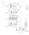
- Fig. 5 illustrates an example of the identification information 13a.
- the identification information 13a mainly has a physical address section 101, a serial number section 102, a real address section 103, and the temporary address section 104.
- the physical address section 101 contains the physical address 101a.
- the serial number section 102 contains the serial numbers 102a of the print substrates 51p and 52p.
- the real address section 103 contains the real address 103a which is set from the remote control unit 43.
- the temporary address section 104 contains the temporary address 104a which is able to be arbitrarily set without the remote control unit 43.
- the physical address 101a is set based on the serial numbers 102a of the print substrates 51p and 52p.
- the serial numbers 102a of the print substrates 51p and 52p are unique numbers for each of the print substrates 51p and 52p, but these are changed to an address which is formed from, for example, a three digit number.
- the real address 103a is an address which is set from the remote control unit 43.
- a technician inputs the real address 103a by operating the remote control unit 43, the communication sections 51a and 52a of the print substrates 51p and 52p of the air conditioning unit 50 receive the real address 103a when transmitted to the air conditioning unit 50, and the real address 103a which is received by the control sections 51b and 52b is stored in the memory sections 51c and 52c.
- the real address 103a is an address which is formed from, for example, a three digit number.
- the temporary address 104a is an address which is able to be arbitrarily set without the remote control unit.
- the temporary address 104a is an address with the same format as the real address 103a.
- the real address 103a is an address which is formed from a three digit number
- the temporary address 104a is also formed from a three digit number and is an address which does not overlap with the real address 103a.
- the same format as the real address 103a has the meaning of the same data format and if the real address 103a is, for example, three bits of data, the temporary address 104a is also three bits of data. Accordingly, it is possible to use the same program in cases where either the real address 103a or the temporary address 104a is used as the logical address 105a.
- the identification information 13a has a machine number section which contains the machine number of the air conditioning unit 50, a product classification code section which contains the product classification code of the air conditioning unit 50, and the like.
- the driving information 13b of the air conditioning unit 50 which is collected using the information collecting section 12a, is accumulated and stored in the memory section 13.
- the memory section 13 is configured so as to be able to store the driving information 13b in predetermined time periods (30 minutes in the present embodiment) and the oldest driving information is sequentially deleted each time that the driving information 13b which is new is acquired when the predetermined period of time is exceeded.
- the daily report data 13c is data which groups together the driving history and the driving state of each of the air conditioning units 50 for one day and includes the highest value and the lowest value among values which are detected using the various types of sensors each day, the total operating time of the air conditioning unit 50 each day, and the like.
- the original data of the daily report data 13c which is stored in the memory section 13 is data being processed before completion of the daily report data 13c which is transmitted to the offsite controller 20 as a final product.
- the daily report data 13c is processed based on the driving information 13b in predetermined intervals (30 minutes in the present embodiment) and is transmitted to the offsite controller 20 via the network side communication section 11a once a day at a predetermined time. Then, when transmitting of the daily report data 13c to the offsite controller 20 is complete, the daily report data 13c which has been transmitted in the past is deleted from the memory section 13.
- the output section 14 and the input section 15 are integrally configured as a display with a touch panel function and a speaker function.
- An input screen where buttons and the like which receive inputting of control commands with regard to the air conditioning units 50 are lined up, is displayed on the display and, when a manager presses a button, processing which corresponds to the button is executed in the local controller 10a. For example, in a case where turning on of the power supply of the air conditioning unit 50 is selected by the manager by operating a button on the display, a control command, which commands that the power supply of the air conditioning unit 50 is turned on, is transmitted to the control sections 51b and 52b of the air conditioning unit 50 via the air conditioning unit side communication section 11b.
- the offsite controller 20 is disposed in the offsite management center 2 and is connected to the local controllers 10a, 10b, and so on in the buildings 1a, 1b, and so on via the communication network 4 such as the Internet.
- the offsite controller 20 mainly has a communication section 21, a control section 22, and a memory section 23.
- the offsite controller 20 is a group of computers which is formed from a plurality of server computers in practice and the offsite controller 20 is configured as a whole by these computers working together.
- the communication section 21 is an interface with regard to the communication network where an Ethernet (registered trademark) or the like is used and the offsite controller 20 is able to connect with the communication network 4.
- the control section 22 is mainly formed from a CPU and has an offsite management section 22a and an information receiving section 22b due to control programs for offsite controller being executed.
- the information receiving section 22b receives the logical addresses 105a and the like which are sent from the local controllers 10a, 10b, and so on, information which relates to the air conditioning units 50, and the daily report data 13c which groups together the abnormality report data and the driving information 13b as a report via the communication section 21 and stores this in the memory section 23.
- the offsite management section 22a manages the air conditioning units 50 in each area using the logical addresses 105a based on the abnormality report data and the daily report data 13c.
- the air conditioning unit 50 is specified using the logical address 105a, and processing for dispatching a technician to the air conditioning unit 50, for example, communicating with the technician using emails is performed.
- Detailed information which relates to the air conditioning unit 50 which is a problem such as the machine type name and location is acquired by searching air conditioning unit information 23a using the logical address 105a and is notified to the technician.
- the memory section 23 is formed from a memory device such as a RAM or a hard disk and stores the air conditioning unit information 23a and the report data 13a.
- the air conditioning unit information 23a is information which relates to the air conditioning unit 50 such as the logical address 105a, the LC identification number 13d, machine number, product code, machine type name, location (in the case of the indoor unit 52), and refrigerant system (in the case of the outdoor unit 51) and stored information which is transmitted from the local controllers 10a, 10b, and so on.
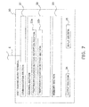
- the test driving work terminal 30 is a terminal such as a PC which is used in test driving work and executes a program which is referred to as a test driving tool.
- the test driving work terminal 30 has a communication section 31, a control section 32, a memory section 33, an output section 34, and an input section 35.
- the communication section 31 is an interface with regard to the communication network 5 where an Ethernet (registered trademark) is used.
- the memory section 33 is formed from a RAM, a hard disk, or the like and stores a test driving tool program (which is not shown in the diagram) and the like.
- the output section 34 is a display such as a LCD.
- the input section 35 is a keyboard, a mouse, or the like.
- the control section 32 is mainly formed from a CPU.
- the control section 32 has a temporary address setting reception section 32a and a temporary address setting section 32b when the test driving tool program is executed.
- the temporary address setting reception section 32a receives setting of the temporary addresses 104a.
- the temporary address 104a which is input via the input section 35 with regard to the air conditioning unit 50 which is specified, is temporarily stored in the memory section 33 and the temporary address 104a is transmitted to the local controller 10a via the communication section 31.
- the temporary address setting section 32b automatically sets the temporary addresses 104a for the air conditioning units 50 based on the physical addresses 101a. For example, a number which is in sequence with the ascending order of the physical addresses 101 a in each of the refrigerant systems is set as the temporary address 104a for the air conditioning unit 50 where the real address 103a is not set.
- test driving work in the air conditioning management system 100 will be described next using the flow chart in Fig. 8 .
- step S101 necessary construction for setting up and wiring of the devices is performed (step S101). For example, in a case where the air conditioning units 50 have not yet been introduced into a building, setting up of the devices such as the air conditioning units 50 and the local controller 10a, connecting of the local controller 10a to the communication network 4 such as the Internet, wiring the dedicated air conditioning unit communication wiring 6 between the air conditioning units 50 and the local controller 10a, and the like is performed. In a case where the air conditioning units 50 and the local controller 10a have already been introduced, construction for settings and wiring and the like is performed for connecting of the local controller 10a to the communication network 4 such as the Internet. Updating of control programs for the local controller 10a and the like is also performed.
- a technician sets the real addresses 103a for each of the air conditioning units 50 (step S102).
- the technician enters each of the rooms where the air conditioning units 50 are disposed, inputs the real addresses 103a by operating the remote control unit 43, and transmits the real addresses 103a to the air conditioning unit 50.
- the real address 103a is input with regard to the indoor unit 52 using the remote control unit 43 and the real address 103a, which is transmitted to the memory section 52c of the print substrate 52p of the indoor unit 52, is stored when the real address 103a is transmitted.
- the real addresses 103a by setting the real addresses 103a using the remote control unit 43 while visually confirming the actual unit, it is possible to associate the real address 103a and the indoor unit 52 which is disposed in a room which is specified.
- a corresponding relationship between the indoor unit 52 and the real address 103 which is referred to such that "the air conditioners with the real address of 1 is the air conditioner in the meeting room 1 on the first floor", is input from the test driving tool and is stored as the identification information 13a which is in the memory section 13 of the local controller 10a.
- the real addresses 103a are given to all of the air conditioning units 50, but it is not possible to set the real address 103a for the air conditioning unit 50 in a case where the location where the air conditioning unit 50 is disposed is off limits for entry due to any circumstances.
- the technician checks whether the real address 103a is set for all of the air conditioning units 50 and, in a case where there is an air conditioning unit 50 where the real address 103a is not set, setting of the temporary address 104a is performed for the air conditioning unit 50 (step S103).
- the test driving work terminal 30 which is carried onsite is connected to the local controller 10a via the communication network 5 such as a LAN, the test work tool in the test driving work terminal 30 is activated and the temporary address 104a is set using the test driving tool. This work will be described later in further detail.
- the technician When the real address 103a or the temporary address 104a is set for all of the air conditioning units 50, the technician next performs test driving for the air conditioning management system 100 (step S104).
- the test driving information such as the LC identification number of the local controller 10a, the logical addresses 105a of each of the air conditioning units 50, product classification codes, machine type name, machine number, system name (in the case of the outdoor unit 51), and location (in the case of the indoor unit 52) is transmitted to the offsite controller 20 using the driving information transmitting section 12d of the local controller 10a.
- the logical address 105a is the real address 103a in a case where the real address 103a is contained in the real address section 103 of the identification information 13a.
- the real address 103a is seen as not being contained when the value of the real address 103a which is contained is zero or a null value which is the initial value.
- the logical address 105a is the temporary address 104a which is contained in the temporary address section 104 of the identification information 13a in a case were the real address 103a is not contained. This information is stored in the memory section 23 as the air conditioning unit information 23a in the offsite controller 20 which receives this information.
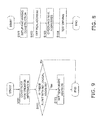
- Fig. 9 is a flow chart illustrating the work as in step S103 described above in further detail.
- the identification information constructing section 12b constructs the identification information 13a.
- a technician presses a button to "start checking" (refer to Fig. 13 ) which is on the test driving tool screen
- an identification information constructing command is transmitted to the local controller 10a.
- the identification information constructing section 12b stores the identification information 13a which is current in the memory section as the old identification information.
- the identification information constructing section 12b transmits a command to each of the air conditioning units 50 such that information such as the serial numbers 102a of the print substrates 51p and 52p, the physical addresses 101a, the real addresses 103a, and the machine number is transmitted.
- the air conditioning units 50 which receives this command transmits this information to the local controller 10a.
- the identification information constructing section 12b stores the information in the memory section 13 as the identification information 13a.
- the identification information constructing section 12b compares the old identification information and the identification information 13a using the serial numbers 102a of the print substrates 51p and 52p, and the temporary address 104a which is set for the air conditioning unit 50 in the old identification information is contained in the temporary address section 104 of the identification information 13a which relates to the air conditioning unit 50.
- the content of the identification information 13a is transmitted to the test driving work terminal 30 and is displayed on the test driving tool screen.
- step S 112 the technician refers to the content of the identification information 13a which is displayed on the test driving tool screen and checks whether or not there are the air conditioning units 50 where both the real address 103a and the temporary address 104a are not set. In a case where there are the air conditioning units 50 where both the real address 103a and the temporary address 104a are not set, the flow proceeds to step S113. In a case where there are none of the air conditioning units 50 where both the real address 103a and the temporary address 104a are not set, the flow proceeds to step S114.
- step S113 the technician sets the temporary address 104a with regard to the air conditioning units 50 where both the real address 103a and the temporary address 104a are not set.
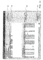
- a button B2 to "set A/N address" (refer to Fig. 10 ) on the screen, a screen is displayed as shown in Fig. 11 .
- the technician it is possible for the technician to automatically set all of the temporary addresses 104a in one batch or to individually set the temporary addresses104a.
- a button B3 to "automatically allocate in one batch" (refer to Fig.
- the temporary address setting section 32b automatically allocates the temporary addresses 104a based on the respective physical addresses 101a for all of the air conditioning units 50 where both the real address 103a and the temporary address 104a are not set. For example, a number, which is open in the ascending order of the physical addresses 101a in each of the refrigerant systems, is allocated as the temporary address 104a. A number which is open is a number which is not yet allocated to any of the air conditioning units 50 as the real address 103a or the temporary address 104a.
- a button B4 to "individually allocate outdoor units” and a button B5 to "individually allocate indoor units" are enabled.
- a screen is displayed as shown in Fig. 12 .
- the technician allocates the temporary addresses 104a to the air conditioning units 50 by selecting a number which is open from a pull down list L1 on the screen.
- the screen returns to the screen in Fig. 11 and the temporary addresses 104a which are allocated are transmitted to the local controller 10a when the technician presses the "OK" button B6 and the temporary address setting reception section 12g in the local controller 10a contains the temporary address 104a which is received in the temporary address section 104 of the identification information 13a which relates to the air conditioning unit 50 which is the target for setting the temporary address.
- Fig. 13 shows an exemplification of changes to the identification information 13a in the series of work described above.
- 002 is set as the temporary address 104a for the air conditioning unit 50 where the physical address 101a is 02 and where both the real address 103a and the temporary address 104a are not set.
- the driving information 13b which is transmitted from each of the air conditioning units 50 in predetermined intervals (one minute in the present embodiment), is collected using the information collecting section 12a.
- the driving information 13b which is collected is accumulated and stored in the memory section 13.
- the daily report data 13c is processed based on the driving information 13b in predetermined intervals (30 minutes in the present embodiment). At this time, the associating section 12c associates the driving information 13b and each of the air conditioning units 50 using the logical addresses 105a. The daily report data 13c is transmitted to the offsite controller 20 via the network side communication section 11a one a day at a predetermined time.
- the abnormality report data is created and the abnormality report data is immediately transmitted to the offsite controller 20.
- the offsite management section 22a of the offsite controller 20 refers to the daily report data 13c which is stored in the memory section 23 and checks the presence or absence of abnormalities or faults and the like. In a case where an abnormality or a fault is detected or in a case where the abnormality report data is received, the offsite management section 22a of the offsite controller 20 searches the air conditioning unit information 23 a using the logical addresses 105a, specifies the air conditioning unit 50 which is the problem, and notifies the technician using an email or the like. That is, the offsite management section 22a manages each of the air conditioning units 50 using the logical addresses 105a.
- identification information is constructed (step S111).
- step S 112 there is checking of whether or not there are the air conditioning units 50 where both the real address 103a and the temporary address 104a are not set.
- the work ends In a case where there are none of the air conditioning units 50 where both the real address 103a and the temporary address 104a are not set, the work ends.
- the real address 103a is set with regard to the air conditioning unit 50 where the print substrates 51p and 52p are replaced, there should not any of the air conditioning units 50 where both the real address 103a and the temporary address 104a are not set and the work ends.
- the indoor unit 52 is removed, there should not any of the air conditioning units 50 where both the real address 103a and the temporary address 104a are not set as exemplified in Fig. 17 and the work ends.
- step S213 the technician sets the temporary address 104a with regard to the air conditioning units 50 where both the real address 103a and the temporary address 104a are not set.
- the button B2 When the technician presses the button B2 to "set A/N address" (refer to Fig. 10 ) on the test driving tool screen, the screen is displayed as shown in Fig. 11 .
- the button B4 When the technician selects the air conditioning units 50 individually by clicking on the screen using a mouse, the button B4 to "individually allocate outdoor units” and the button B5 to “individually allocate indoor units” are enabled.
- the technician presses the button B4 to "individually allocate outdoor units” or the button B5 to “individually allocate indoor units” the screen is displayed as shown in Fig. 12 .
- the candidates for the temporary address 104a are displayed in the pull down list L1 on the screen.
- the candidates for the temporary address 104a are the real address 103a or the temporary address 104a of the air conditioning unit 50 which is a hit.
- a plurality of the candidates for the temporary addresses 104a are displayed. The technician selects one from the temporary addresses 104a which are displayed and allocates the temporary address 104a to the air conditioning unit 50 which is the target for setting the temporary address.
- the screen returns to the screen in Fig. 11 and the temporary address 104a which is allocated is transmitted to the local controller 10a when the technician presses the "OK" button B6 and the temporary address setting reception section 12g in the local controller 10a contains the temporary address 104a which is received in the temporary address section 104 of the identification information 13a which relates to the air conditioning unit 50 which is the target for setting the temporary address.
- Fig. 15 shows an exemplification of changes to the identification information 13a in the series of work described above in a case where the print substrates 51p and 52p of the air conditioning unit 50 are replaced.
- the print substrates 51p and 52p of the air conditioning unit 50 which is second from the top are replaced and the serial numbers 102a change, and the physical address 101a is automatically set and the physical address 101a which is different is set as a result.
- the temporary address 104a which was set for the air conditioning unit 50 is no longer set. Therefore, the technician set the same temporary address 104a for the air conditioning unit 50 using the test driving tool. Due to this, even when the print substrates 51p and 52p are replaced, the air conditioning unit 50 is recognized by the local controller 10a and the offsite controller 20 as the same as before the replacing of the print substrates 51p and 52p.
- each of the air conditioning units 50 are managed using the logical addresses 105a separately to the physical addresses 101a which are used in controlling of the air conditioning units 50 such as control of the compressor and the like in the outdoor units 52 and control of the fan and the like in the indoor units 51.
- the real address 103a which is set via the remote control unit 43, is used as the logical address 105a
- the temporary address 104a which is able to be arbitrarily set without the remote control unit 43, is used as the logical address 105a in a case where the real address 103a is not set.
- the offsite management section 22a manages each of the air conditioning units 50 using the logical addresses 105a.
- the physical addresses 101 a are automatically set based on the serial numbers 102a of the print substrates 51 p and 52p using the physical address setting section 12f. For this reason, work for setting the physical addresses 101a, which is used in communication between the outdoor unit 51 and the indoor unit 52, is not necessary.
- the real address 103a and the temporary address 104a have the same data format. Due to this, it is not necessary to change a program depending on whether either of the real address 103a or the temporary address 104a is used as the logical address 105a.
- the real address 103a has zero or a null value as the initial setting value. Then, the real address 103a is seen as not being set by the associating section 12c when the value of the real address 103a is zero or a null value. Due to this, it is possible to easily identify whether the real address 103a is set or not set.
- the physical addresses 101a of all of the air conditioning units 50 are automatically updated by the physical address setting section 12f when even one of the print substrates 51p and 52p are replaced.
- the identification information 13a is constructed by the identification information constructing section 12b
- only the physical addresses 101a in the physical address sections 101 is updated and the real addresses 103a and the temporary addresses 104a (the logical addresses 105a) are not changed for the air conditioning units 50 where the print substrates 51p and 52p are not replaced.
- the real addresses 103a or the temporary addresses 104a which are set before the replacing is set by the technician. Due to this, the burden and costs of management are reduced without changing the corresponding relationship of the logical addresses 105a and the air conditioning units 50.
- the temporary address setting section 32b of the test driving work terminal 30 sets the temporary address 104a using the ordering of the physical addresses 101a in each of the refrigerant systems with regard to the air conditioning units 50 where the real address 103a is not set. Due to this, it is possible to reduce the burden of setting the temporary address 104a.
- the technician activates the test driving tool in the test driving work terminal 30 and performs checking of the logical addresses 105a and setting of the temporary addresses 104a.
- the test driving tool may be activated in the local controllers 10a, 10b, and so on and checking of the logical addresses 105a and setting of the temporary addresses 104a may be performed.
- the control section 12 of the local controller 10a, 10b, and so on has a temporary address setting section.
- the present invention is possible for the present invention to be used in offsite management of a plurality of air conditioning units.
Landscapes
- Engineering & Computer Science (AREA)
- General Engineering & Computer Science (AREA)
- Chemical & Material Sciences (AREA)
- Mechanical Engineering (AREA)
- Combustion & Propulsion (AREA)
- Physics & Mathematics (AREA)
- General Physics & Mathematics (AREA)
- Automation & Control Theory (AREA)
- Fuzzy Systems (AREA)
- Mathematical Physics (AREA)
- Signal Processing (AREA)
- Human Computer Interaction (AREA)
- Air Conditioning Control Device (AREA)
Abstract
Description
- The present invention relates to an air conditioning management system.
- In an air conditioning system in the background art where a plurality of indoor units are connected with one outdoor unit, controlling is performed by each of the indoor units being specified by identifying using unique information such as a serial number. For example, a technique is proposed in patent document 1 (Japanese Unexamined Patent Application Publication No.
2000-74461 - In addition, in the air conditioning system where the plurality of indoor units are operated using one remote control unit, setting of addresses for each of the indoor units from the remote control unit in order to identify each of the indoor units is described in patent document 1.
- However, in a building such as an office building where a plurality of the air conditioning units are disposed, a means is necessary for identifying each of the plurality of air conditioning units in order to introduce a service where centralized management of a plurality of air conditioning units is provided.
- In the technique in PTL 1, the serial number changes when the print substrate is replaced due to a breakage or the like and the order of the serial numbers of the plurality of air conditioning units changes due to this. To accompany this, the addresses which are set for each of the air conditioning units also change. In addition, the order of the serial numbers of the plurality of indoor units changes in a case where the indoor unit which is new is added and the addresses which are set for each of the indoor units also change to accompany this. In addition, it is not possible to confirm the serial numbers to begin with from the outer appearance of the print substrate or the like and it is also difficult to ascertain the addresses which are automatically set based on the serial number. Due to this, it is difficult to ascertain the corresponding relationship between the addresses and each of the indoor units and the burden and cost of management increases.
- On the other hand, a method of setting the addresses for each of the air conditioning units manually using an operating means such as a remote control unit is more preferable from the point that it is possible to set the addresses while visually confirming the set units. However, there is a demerit in that it is not possible to set the addresses in a case where the location where the air conditioning units are disposed is off limits to entry due to any circumstances. For example, it is often the case that bank vaults or offices of important people are off limits to entry. A technician who goes out and visits for setting the real addresses needs to goes out and visit again in order to set the addresses of the air conditioning units in locations where it is not possible to gain entry, and the burden and costs of work for introducing the system increase.
- The object of the present invention is to provide an air conditioning system where it is possible to reduce the burden and costs of work for introducing the system.
- An air conditioning management system according to a first aspect of the present invention manages a plurality of air conditioning units, which each have a unique physical address, using logical addresses and is provided with a local controller which collects driving information for each of the air conditioning units and an operating means for each of the air conditioning units with the operating means arranged in the vicinity of each of the air conditioning units. The local controller has a memory section, an information collecting section, and an associating section. The memory section stores identification information for each of the air conditioning units. The information collecting section collects the driving information for each of the air conditioning units. The associating section associates the driving information with the logical addresses. The identification information for each of the air conditioning units has a physical address section which contains the physical address, a real address section which contains a real address, and a temporary address section which contains a temporary address. The real address is set from the operating means. It is possible for the temporary address to be arbitrarily set without the operating means. The associating section uses the real address as the logical address in a case where the real address is set and uses the temporary address as the logical address in a case where the real address is not set. The plurality of air conditioning units include an outdoor unit and an indoor unit which communicate with each other using the physical address.
- That is, the air conditioning system according to the present invention manages each of the air conditioning units using the logical addresses separately to the physical addresses. Then, the real address, which is set via the operating means which is a remote control unit or the like, is used as the logical address and the temporary address, which is able to be arbitrarily set without the operating means which is a remote control unit or the like, is used as the logical address in a case where the real address is not set. Due to this, it is possible to manage each of the air conditioning units using the temporary addresses even in a case where the location where the air conditioning units are disposed is off limits to entry during work for introducing the system due to any circumstances and it is not possible to set the real address using the operating means which is a remote control unit or the like. Accordingly, the burden and costs of work for introducing the system such as repeat visits by a technician are reduced.
- An air conditioning management system according to a second aspect of the present invention is the air conditioning management system according to the first aspect of the present invention where an offsite controller is further provided. The offsite controller is connected to the local controller via a communication network. The offsite controller has an information receiving section and an offsite management section. The information receiving section receives the driving information from the local controller. The offsite management section manages each of the air conditioning units using the logical addresses.
- Due to this, offsite management of the air conditioning units is possible even if the location where the air conditioning units are disposed is off limits to entry and it is not possible to set the real address.
- An air conditioning management system according to a third aspect of the present invention is the air conditioning management system according to the first aspect or the second aspect of the present invention where each of the air conditioning units has a communication substrate. The physical address is determined based on the identification information of the communication substrate.
- Here, since the physical address is automatically determined based on the identification information of the communication substrate, work for setting the physical address, which is used in communication between the outdoor unit and the indoor unit, is not necessary.
- An air conditioning management system according to a fourth aspect of the present invention is the air conditioning management system according to any of the first aspect to the third aspect of the present invention where the real address and the temporary address are information with the same format.
- Due to this, it is not necessary to change a program depending on whether either of the real address or the temporary address is used as the logical address.
- An air conditioning management system according to a fifth aspect of the present invention is the air conditioning management system according to any of the first aspect to the fourth aspect of the present invention where the real address has a predetermined initial value. The associating section uses the temporary address as the logical address in a case where the real address is the initial value.
- Due to this, it is possible to easily identify whether the real address is set or not set.
- An air conditioning management system according to a sixth aspect of the present invention is the air conditioning management system according to any of the first aspect to the fifth aspect of the present invention where the local controller further has an address updating section. The address updating section updates only the physical address when the communication substrate is replaced.
- Only the physical address is automatically updated when the communication substrate is replaced. Due to this, the burden and costs of management are reduced.
- An air conditioning management system according to a seventh aspect of the present invention is the air conditioning management system according to any of the first aspect to the sixth aspect of the present invention where the local controller further has a first temporary address setting reception section which receives setting of the temporary addresses.
- Due to this, it is possible to set the temporary address from the local controller even in a case where it is not possible to gain entry into the location where the air conditioning units are disposed. Accordingly, wasteful costs such as repeat visits by a technician are reduced.
- An air conditioning management system according to an eighth aspect of the present invention is the air conditioning management system according to any of the first aspect to the seventh aspect of the present invention where a temporary address setting device is further provided. The temporary address setting device has a temporary address setting reception section.
- Due to this, it is possible to set the temporary address from the temporary address setting device onsite or offsite through the Internet even if it is not possible to gain entry into the location where the air conditioning units are disposed. Accordingly, wasteful costs such as repeat visits by a technician are reduced.
- An air conditioning management system according to a ninth aspect of the present invention is the air conditioning management system according to the eighth aspect of the present invention where the temporary address setting device further has a temporary address setting section. The temporary address setting section sets the temporary addresses based on the physical addresses.
- Due to this, it is possible to set the temporary addresses based on the physical addresses for the air conditioning units where the real address is not set and it is possible to reduce the burden of setting the temporary address.
- In the air conditioning management system according to the first aspect of the present invention, the burden and costs of work for introducing the system are reduced.
- In the air conditioning management system according to the second aspect of the present invention, offsite management of the air conditioning units is possible even if the location where the air conditioning units are disposed is off limits to entry and it is not possible to set the real address.
- In the air conditioning management system according to the third aspect of the present invention, work for setting the physical address, which is used in communication between the outdoor unit and the indoor unit, is not necessary.
- In the air conditioning management system according to the fourth aspect of the present invention, it is not necessary to change a program depending on whether either of the real address or the temporary address is used as the logical address.
- In the air conditioning management system according to the fifth aspect of the present invention, it is possible to easily identify whether the real address is set or not set.
- In the air conditioning management system according to the sixth aspect of the present invention, the burden and costs of management are reduced.
- In the air conditioning management system according to the seventh aspect and the eighth aspect of the present invention, wasteful costs are reduced.
- In the air conditioning management system according to the ninth aspect of the present invention, it is possible to reduce the burden of setting the temporary address.
-
- [
Fig. 1] Fig. 1 is an overall configuration diagram of an air conditioning management system. - [
Fig. 2] Fig. 2 is a system configuration diagram of a building. - [
Fig. 3] Fig. 3 is a block diagram illustrating a configuration of an outdoor unit and an indoor unit. - [
Fig. 4] Fig. 4 is a block diagram illustrating a configuration of a local controller. - [
Fig. 5] Fig. 5 is a diagram exemplifying identification information. - [
Fig. 6] Fig. 6 is a block diagram illustrating a configuration of an offsite controller. - [
Fig. 7] Fig. 7 is a block diagram illustrating a configuration of a test driving work terminal. - [
Fig. 8] Fig. 8 is a flow chart of test driving work. - [
Fig. 9] Fig. 9 is a flow chart of address checking and setting work. - [
Fig. 10] Fig. 10 is example 1 of a test driving tool screen. - [
Fig. 11] Fig. 11 is example 2 of a test driving tool screen. - [
Fig. 12] Fig. 12 is example 3 of a test driving tool screen. - [
Fig. 13] Fig. 13 is a diagram exemplifying changes to identification information in test driving work. - [
Fig. 14] Fig. 14 is a flow chart of work after replacing a print substrate and removing an indoor unit. - [
Fig. 15] Fig. 15 is a diagram exemplifying changes to identification information when replacing a print substrate. - [
Fig. 16] Fig. 16 is a diagram exemplifying changes to identification information when adding an indoor unit. - [
Fig. 17] Fig. 17 is a diagram exemplifying changes to identification information when removing an indoor unit. - An embodiment of an air conditioning management system according to the present invention will be described below with reference to the diagrams.
-
Fig. 1 is a diagram illustrating an overall configuration of an airconditioning management system 100. - The air
conditioning management system 100 is a system for managing a plurality ofair conditioning units 50 which are each disposed at a plurality ofbuildings buildings air conditioning systems local controllers offsite controller 20 is arranged at anoffsite management center 2 which is a distance from thebuildings local controllers air conditioning systems buildings local controllers air conditioning systems Fig. 2 ). Theoffsite controller 20 is connected to thelocal controllers communication network 4 such as the Internet. - The configuration of the
buildings Fig. 2 is a diagram illustrating the configuration of thebuilding 1a in further detail. The configurations of thebuildings 1b and so on are the same as for thebuilding 1a. - As shown in
Fig. 2 , a plurality of theair conditioning units 50 and thelocal controller 10a, which is connected to the plurality ofair conditioning units 50 using a dedicated air conditioningunit communication wiring 6, are disposed in thebuilding 1a. A plurality ofoutdoor units indoor units outdoor units 51 using the dedicated air conditioningunit communication wiring 6 are included in the plurality ofair conditioning units 50. In the example inFig. 2 , thelocal controller 10a is connected with each of theoutdoor units 51 using the dedicated air conditioningunit communication wiring 6. Here, a test drivingwork terminal 30, which is connected with thelocal controller 10a using acommunication network 5 such as a LAN, is not a permanent fixture and is used by being carried in by a technician during a portion of test driving work for the airconditioning management system 100 at thebuilding 1a. As such, the test drivingwork terminal 30 is not represented inFig. 1 . - In the air
conditioning management system 100,physical addresses 101a are used in controlling theair conditioning units 50 andlogical addresses 105a are used separately to thephysical addresses 101a in managing theair conditioning units 50. It is possible for areal address 103a and atemporary address 104a which will be described later to be set for each of theair conditioning units 50 and either of these addresses are used as thelogical address 105a. - Communication between the
outdoor units 51 and theindoor units 52 which is performed in order to control compressors, fans, and the like uses thephysical addresses 101a. That is, controlling of theoutdoor units 51 and theindoor units 52 is performed using thephysical addresses 101a when controlling while theoutdoor units 51 and theindoor units 52 are communicating with each other. That is, theoutdoor unit 51 identifies the plurality ofindoor units 52, with which theoutdoor unit 51 is connected, using the respectivephysical addresses 101a. Thephysical address 101a is an address which is given to each of theair conditioning units 50 based onserial numbers 102a ofprint substrates Fig. 3 ) in each of theair conditioning units 50 and is data which is smaller in size than theserial numbers 102a of theprint substrates unit communication wiring 6 which connects between theair conditioning units 50 is very small and communication speed is faster when using thephysical address 101 a than when using theserial numbers 102a of theprint substrates - On the other hand, each of the
air conditioning units 50 is identified using thelogical addresses 105a when managing each of theair conditioning units 50 such as when accumulating driving information for theair conditioning units 50 and detecting abnormalities by analyzing the driving information. This is because thephysical addresses 101a of each of theair conditioning units 50, where theprint substrates serial numbers 102a of theprint substrates physical addresses 101a are automatically set and there is a possibility that the corresponding relationship between thephysical addresses 101a and theair conditioning units 50 will change even with theair conditioning units 50 where theprint substrates air conditioning units 50 using thephysical addresses 101a, it is necessary that the corresponding relationship is always tracked and the burden and costs of management increase. Therefore, there is a configuration where thelogical address 105a is set for each of theair conditioning units 50 separately to thephysical address 101a and at least the corresponding relationship between thelogical addresses 105a and theair conditioning units 50 where theprint substrates air conditioning units 50 being identified and managed using thelogical addresses 105a. - The address which is used as the
logical address 105a is thereal address 103a or thetemporary address 104a. There is a configuration so that it is possible to set thereal address 103a for each of theair conditioning units 50 only by operating aremote control unit 43 while looking at the actual unit. In contrast to this, there is a configuration so that it is possible to arbitrarily set thetemporary address 104a via thelocal controller 10a without operating theremote control unit 43. Thetemporary address 104a is an address which is sets as an address which is temporary as a substitute in a case where access into the location where theair conditioning units 50 are disposed is not possible due to any circumstances and it is not possible to set thereal address 103a using theremote control unit 43. Due to this, it is possible to manage each of theair conditioning units 50 by using thetemporary addresses 104a even in a case where the location where the air conditioning units are disposed is off limits for entry during work for introducing the system due to any circumstances and it is not possible to set thereal address 103a using theremote control unit 43. Accordingly, the burden and costs of work for introducing the system such as repeat visits by a technician is reduced. - The plurality of the
air conditioning units 50 in the present embodiment include theoutdoor units 51 and theindoor units 52.Fig. 3 is a block diagram which represents this configuration in further detail with theoutdoor unit 51 and theindoor unit 52 out of the plurality ofair conditioning units 50. The configurations of theoutdoor unit 51 and theindoor unit 52 out of the plurality ofair conditioning units 50 will be described below with reference toFig. 3 . - The
outdoor unit 51 has a compressor, a heat exchanger, an expansion mechanism, a fan, and the like which are not shown in the diagrams and is disposed on the outside of thebuilding 1a. Theindoor units 52 has a fan, a heat exchanger, and the like which are not shown in the diagrams and is disposed inside each room in thebuilding 1a. Theoutdoor unit 51 and theindoor unit 52 are connected using a refrigerant pipe which is not shown in the diagrams and configure a refrigerant circuit. In addition, various types of sensors which are not shown in the diagrams are attached to theoutdoor unit 51 and theindoor unit 52. For example, a room temperature sensor which detects the temperature of a room in which theindoor unit 52 is disposed is attached to theindoor unit 52. An outdoor temperature sensor which detects the outdoor temperature, a discharge temperature sensor which detects the discharge temperature which is the temperature of refrigerant at a discharge pipe in the compressor, a discharge pressure sensor which detects the discharge pressure which is the pressure of refrigerant at a discharge pipe in the compressor, a suction pressure sensor which detects the suction pressure which is the pressure of refrigerant at a suction pipe in the compressor, and the like are attached to theoutdoor unit 51. - In addition, the
outdoor unit 51 and theindoor unit 52 respectively have theprint substrates print substrates communication sections control sections memory sections - The
communication sections unit communication wiring 6, transmit a signal through the dedicated air conditioningunit communication wiring 6 in accordance with commands from thecontrol sections unit communication wiring 6, and send signals which represent this to thecontrol sections - The
control sections outdoor unit 51 and theindoor unit 52 in accordance with control commands which are input from the manager of thebuilding 1a via thelocal controller 10a and control commands which are input by a typical user in a room via theremote control unit 43, that is, thecontrol sections - In addition, the
control sections outdoor unit 51 or theindoor unit 52 to thelocal controller 10a via thecommunication sections control sections local controller 10a as the driving information in predetermined intervals (one minute in the present embodiment). In addition, thecontrol sections serial numbers 102a of theprint substrates physical addresses 101a and thereal addresses 103a which will be described later, and the like to thelocal controller 10a via thecommunication sections control sections remote control unit 43, to thelocal controller 10a via thecommunication sections - The
memory sections serial numbers 102a of each of theprint substrates physical addresses 101a and thereal addresses 103a, and the like. -
Fig. 4 is a block diagram illustrating a configuration of thelocal controller 10a. The configuration of thelocal controller 10a will be described below. The configurations of the local controllers10b and so on are the same as for thelocal controller 10a. - The
local controller 10a is disposed in thebuilding 1a, for example, in a management room and manages the plurality ofair conditioning units 50 which include theoutdoor units 51 and theindoor units 52 described above which are also disposed in thebuilding 1a. In detail, thelocal controller 10a detects abnormalities in theair conditioning units 50, receives inputting of a driving schedule of theair conditioning units 50, and controls driving of theair conditioning units 50 in accordance with the driving schedule. In addition, thelocal controller 10a is connected with thecommunication network 4 which is a wide-area communication network such as the Internet and is connected with theoffsite controller 20 in theoffsite management center 2 via thecommunication network 4. In addition, thelocal controller 10a is also connected to thecommunication network 5 which is a local communication network such as a LAN in thebuilding 1a. - As shown in
Fig. 4 , thelocal controller 10a mainly has a networkside communication section 11a, an air conditioning unitside communication section 11b, acontrol section 12, amemory section 13, anoutput section 14, and aninput section 15. - The network
side communication section 11a is an interface with regard to a communication network where an Ethernet (registered trademark) or the like is used and it is possible for thelocal controller 10a to connect with communication networks such as the Internet or a LAN. - The air conditioning unit
side communication section 11b is an interface with regard to the dedicated air conditioningunit communication wiring 6 and is able to connect thelocal controller 10a with the dedicated air conditioningunit communication wiring 6. - The
control section 12 is mainly formed from a CPU and has aninformation collecting section 12a, an identificationinformation constructing section 12b, an associatingsection 12c, a drivinginformation transmitting section 12d, anabnormality detecting section 12e, a physicaladdress setting section 12f, and a temporary addresssetting reception section 12g due to control programs for thelocal controller 10a being executed. - The
information collecting section 12a collects drivinginformation 13b which is transmitted from each of theair conditioning units 50 in predetermined intervals (one minute in the present embodiment). In detail, when the air conditioning unitside communication section 11b receives the drivinginformation 13b which is transmitted from each of theair conditioning units 50 and a signal for notifying this is received from the air conditioning unitside communication section 11b, theinformation collecting section 12a accumulates and stores the drivinginformation 13b in thememory section 13. - The identification
information constructing section 12b constructsidentification information 13a for each of theair conditioning units 50. Theidentification information 13a is information as shown inFig. 5 and is information which is for individually identifying each of theair conditioning units 50. The identificationinformation constructing section 12b first stores theidentification information 13a, which is currently in thememory section 13, in thememory section 13 as old identification information. Next, the identificationinformation constructing section 12b transmits a command so that various types of information which are for identifying are transmitted with regard to each of theair conditioning units 50 via the air conditioning unitside communication section 11b. Each of theair conditioning units 50 which receive this command transmits machine numbers, theserial numbers 102a of theprint substrates physical addresses 101a, thereal addresses 103a, and the like to thelocal controller 10a. When this information is received via the air conditioning unitside communication section 11b, the identificationinformation constructing section 12b stores this information in thememory section 13 as theidentification information 13a. - In addition, in a case where there is old identification information, the identification
information constructing section 12b compares the old identification information and theidentification information 13a using theserial numbers 12a of theprint substrates temporary address 104a which is set for theair conditioning unit 50 in the old identification information is contained in atemporary address section 104 in theidentification information 13a which relates to theair conditioning unit 50. - The associating
section 12c associates the drivinginformation 13b with thelogical addresses 105a. In detail, the associatingsection 12c createsdaily report data 13c which will be described later on the basis of the drivinginformation 13b, searches for theidentification information 13a using thephysical address 101a of theair conditioning unit 50 where the drivinginformation 13b is added at this time, and specifies thereal address 103a or thetemporary address 104a of theair conditioning unit 50 which has thephysical address 101a. The associatingsection 12c uses thereal address 103a as thelogical address 105a in a case where thereal address 103a is set and uses thetemporary address 104a as thelogical address 105a in a case where thereal address 103a is not set. Here, thereal address 103a is initialized as zero or a null valve and thereal address 103a is seen as not being set when the value of thereal address 103a is the initial value without any changes. The associatingsection 12c adds thelogical address 105a of each of theair conditioning units 50 to thedaily report data 13c which relates to each of theair conditioning units 50. - The driving
information transmitting section 12d transmits thedaily report data 13c where the drivinginformation 13b is grouped together as a report to theoffsite controller 20 periodically (for example, once a day) via the networkside communication section 11a. - The
abnormality detecting section 12e determines the presence or absence of abnormalities in each of theair conditioning units 50 based on the drivinginformation 13b which is stored in thememory section 13 at predetermined intervals (one minute in the present embodiment). Here, theabnormality detecting section 12e, where an abnormality is detected, creates abnormality report data and immediately transmits the abnormality report data to theoffsite controller 20 through the networkside communication section 11a. Here, as classification of abnormalities which are detected by theabnormality detecting section 12e, there are the two types of "abnormality" and "warning". Here, the abnormalities which are classified as an "abnormality" refer to states where the device is faulty and the abnormalities which are classified as a "warning" are states where a fault has not yet occurred but a fault is predicted in the near future. - The physical
address setting section 12f sets thephysical addresses 101a based on theserial numbers 102a of theprint substrates air conditioning units 50. In detail, for example, the physicaladdress setting section 12f sets a number which is in sequence with the ascending order of theserial numbers 102a as thephysical addresses 101a for each of theair conditioning units 50. The physicaladdress setting section 12f transmits thephysical addresses 101a, which are set with regard to each of theair conditioning units 50, to each of theair conditioning units 50 via the air conditioning unitside communication section 11b and thephysical addresses 101a are stored in thememory sections print substrates air conditioning units 50. The process for setting thephysical addresses 101a using the physicaladdress setting section 12f is performed each time that theair conditioning system 40a is activated. Accordingly, the ordering of theserial number 102a changes when even just one of theprint substrates air conditioning unit 50 is replaced and there is a possibility that thephysical addresses 101 a of all of theair conditioning units 50 will change. - The temporary address
setting reception section 12g receives the setting of thetemporary addresses 104a. In detail, for example, the temporary addresssetting reception section 12g sets thetemporary address 104a which is input via theinput section 15 for theair conditioning unit 50 which is indicated in the inputting. Thetemporary address 104a which is set is contained in the temporary address section 104 (refer toFig. 5 ) of theidentification information 13a which is related to theair conditioning unit 50 which is the target of the setting. In addition, when the temporary addresssetting reception section 12g receives setting of thetemporary addresses 104a with regard to theair conditioning unit 50 which is specified from the test drivingwork terminal 30 which will be described later via the networkside communication section 11 a, thetemporary address 104a is contained in thetemporary address section 104 in theidentification information 13a which related to theair conditioning unit 50. - The
identification information 13a, the drivinginformation 13b, thedaily report data 13c, and aLC identification number 13d for identifying thelocal controller 10a are stored in thememory section 13. -
Fig. 5 illustrates an example of theidentification information 13a. Theidentification information 13a mainly has aphysical address section 101, aserial number section 102, areal address section 103, and thetemporary address section 104. - The
physical address section 101 contains thephysical address 101a. - The
serial number section 102 contains theserial numbers 102a of theprint substrates - The
real address section 103 contains thereal address 103a which is set from theremote control unit 43. - The
temporary address section 104 contains thetemporary address 104a which is able to be arbitrarily set without theremote control unit 43. - The
physical address 101a is set based on theserial numbers 102a of theprint substrates serial numbers 102a of theprint substrates print substrates - The
real address 103a is an address which is set from theremote control unit 43. A technician inputs thereal address 103a by operating theremote control unit 43, thecommunication sections print substrates air conditioning unit 50 receive thereal address 103a when transmitted to theair conditioning unit 50, and thereal address 103a which is received by thecontrol sections memory sections real address 103a is an address which is formed from, for example, a three digit number. - The
temporary address 104a is an address which is able to be arbitrarily set without the remote control unit. Thetemporary address 104a is an address with the same format as thereal address 103a. For example, if thereal address 103a is an address which is formed from a three digit number, thetemporary address 104a is also formed from a three digit number and is an address which does not overlap with thereal address 103a. In addition, the same format as thereal address 103a has the meaning of the same data format and if thereal address 103a is, for example, three bits of data, thetemporary address 104a is also three bits of data. Accordingly, it is possible to use the same program in cases where either thereal address 103a or thetemporary address 104a is used as thelogical address 105a. - Other than this, although not shown in the diagrams, the
identification information 13a has a machine number section which contains the machine number of theair conditioning unit 50, a product classification code section which contains the product classification code of theair conditioning unit 50, and the like. - In addition, the driving
information 13b of theair conditioning unit 50, which is collected using theinformation collecting section 12a, is accumulated and stored in thememory section 13. Here, thememory section 13 is configured so as to be able to store the drivinginformation 13b in predetermined time periods (30 minutes in the present embodiment) and the oldest driving information is sequentially deleted each time that the drivinginformation 13b which is new is acquired when the predetermined period of time is exceeded. - In addition, the original data of the
daily report data 13c, which is transmitted once a day from thelocal controller 10a to theoffsite controller 20, is stored in thememory section 13. Thedaily report data 13c is data which groups together the driving history and the driving state of each of theair conditioning units 50 for one day and includes the highest value and the lowest value among values which are detected using the various types of sensors each day, the total operating time of theair conditioning unit 50 each day, and the like. The original data of thedaily report data 13c which is stored in thememory section 13 is data being processed before completion of thedaily report data 13c which is transmitted to theoffsite controller 20 as a final product. Thedaily report data 13c is processed based on the drivinginformation 13b in predetermined intervals (30 minutes in the present embodiment) and is transmitted to theoffsite controller 20 via the networkside communication section 11a once a day at a predetermined time. Then, when transmitting of thedaily report data 13c to theoffsite controller 20 is complete, thedaily report data 13c which has been transmitted in the past is deleted from thememory section 13. - The
output section 14 and theinput section 15 are integrally configured as a display with a touch panel function and a speaker function. An input screen, where buttons and the like which receive inputting of control commands with regard to theair conditioning units 50 are lined up, is displayed on the display and, when a manager presses a button, processing which corresponds to the button is executed in thelocal controller 10a. For example, in a case where turning on of the power supply of theair conditioning unit 50 is selected by the manager by operating a button on the display, a control command, which commands that the power supply of theair conditioning unit 50 is turned on, is transmitted to thecontrol sections air conditioning unit 50 via the air conditioning unitside communication section 11b. - The
offsite controller 20 is disposed in theoffsite management center 2 and is connected to thelocal controllers buildings communication network 4 such as the Internet. - As shown in
Fig. 5 , theoffsite controller 20 mainly has acommunication section 21, acontrol section 22, and amemory section 23. Here, theoffsite controller 20 is a group of computers which is formed from a plurality of server computers in practice and theoffsite controller 20 is configured as a whole by these computers working together. - The
communication section 21 is an interface with regard to the communication network where an Ethernet (registered trademark) or the like is used and theoffsite controller 20 is able to connect with thecommunication network 4. - The
control section 22 is mainly formed from a CPU and has anoffsite management section 22a and aninformation receiving section 22b due to control programs for offsite controller being executed. - The
information receiving section 22b receives thelogical addresses 105a and the like which are sent from thelocal controllers air conditioning units 50, and thedaily report data 13c which groups together the abnormality report data and the drivinginformation 13b as a report via thecommunication section 21 and stores this in thememory section 23. - The
offsite management section 22a manages theair conditioning units 50 in each area using thelogical addresses 105a based on the abnormality report data and thedaily report data 13c. In a case where, for example, an abnormality is detected in theair conditioning unit 50, theair conditioning unit 50 is specified using thelogical address 105a, and processing for dispatching a technician to theair conditioning unit 50, for example, communicating with the technician using emails is performed. Detailed information which relates to theair conditioning unit 50 which is a problem such as the machine type name and location is acquired by searching airconditioning unit information 23a using thelogical address 105a and is notified to the technician. - The
memory section 23 is formed from a memory device such as a RAM or a hard disk and stores the airconditioning unit information 23a and thereport data 13a. The airconditioning unit information 23a is information which relates to theair conditioning unit 50 such as thelogical address 105a, theLC identification number 13d, machine number, product code, machine type name, location (in the case of the indoor unit 52), and refrigerant system (in the case of the outdoor unit 51) and stored information which is transmitted from thelocal controllers - The test driving
work terminal 30 is a terminal such as a PC which is used in test driving work and executes a program which is referred to as a test driving tool. The test drivingwork terminal 30 has acommunication section 31, acontrol section 32, amemory section 33, anoutput section 34, and aninput section 35. - The
communication section 31 is an interface with regard to thecommunication network 5 where an Ethernet (registered trademark) is used. - The
memory section 33 is formed from a RAM, a hard disk, or the like and stores a test driving tool program (which is not shown in the diagram) and the like. - The
output section 34 is a display such as a LCD. - The
input section 35 is a keyboard, a mouse, or the like. - The
control section 32 is mainly formed from a CPU. Thecontrol section 32 has a temporary addresssetting reception section 32a and a temporaryaddress setting section 32b when the test driving tool program is executed. - The temporary address
setting reception section 32a receives setting of thetemporary addresses 104a. In detail, for example, thetemporary address 104a, which is input via theinput section 35 with regard to theair conditioning unit 50 which is specified, is temporarily stored in thememory section 33 and thetemporary address 104a is transmitted to thelocal controller 10a via thecommunication section 31. - The temporary
address setting section 32b automatically sets thetemporary addresses 104a for theair conditioning units 50 based on thephysical addresses 101a. For example, a number which is in sequence with the ascending order of thephysical addresses 101 a in each of the refrigerant systems is set as thetemporary address 104a for theair conditioning unit 50 where thereal address 103a is not set. - The test driving work in the air
conditioning management system 100 will be described next using the flow chart inFig. 8 . - In the test driving work, first, necessary construction for setting up and wiring of the devices is performed (step S101). For example, in a case where the
air conditioning units 50 have not yet been introduced into a building, setting up of the devices such as theair conditioning units 50 and thelocal controller 10a, connecting of thelocal controller 10a to thecommunication network 4 such as the Internet, wiring the dedicated air conditioningunit communication wiring 6 between theair conditioning units 50 and thelocal controller 10a, and the like is performed. In a case where theair conditioning units 50 and thelocal controller 10a have already been introduced, construction for settings and wiring and the like is performed for connecting of thelocal controller 10a to thecommunication network 4 such as the Internet. Updating of control programs for thelocal controller 10a and the like is also performed. - Next, a technician sets the
real addresses 103a for each of the air conditioning units 50 (step S102). The technician enters each of the rooms where theair conditioning units 50 are disposed, inputs thereal addresses 103a by operating theremote control unit 43, and transmits thereal addresses 103a to theair conditioning unit 50. For example, thereal address 103a is input with regard to theindoor unit 52 using theremote control unit 43 and thereal address 103a, which is transmitted to thememory section 52c of theprint substrate 52p of theindoor unit 52, is stored when thereal address 103a is transmitted. In this manner, by setting thereal addresses 103a using theremote control unit 43 while visually confirming the actual unit, it is possible to associate thereal address 103a and theindoor unit 52 which is disposed in a room which is specified. For example, a corresponding relationship between theindoor unit 52 and thereal address 103, which is referred to such that "the air conditioners with the real address of 1 is the air conditioner in the meeting room 1 on the first floor", is input from the test driving tool and is stored as theidentification information 13a which is in thememory section 13 of thelocal controller 10a. Here, it is desirable that thereal addresses 103a are given to all of theair conditioning units 50, but it is not possible to set thereal address 103a for theair conditioning unit 50 in a case where the location where theair conditioning unit 50 is disposed is off limits for entry due to any circumstances. - Next, the technician checks whether the
real address 103a is set for all of theair conditioning units 50 and, in a case where there is anair conditioning unit 50 where thereal address 103a is not set, setting of thetemporary address 104a is performed for the air conditioning unit 50 (step S103). In detail, the test drivingwork terminal 30 which is carried onsite is connected to thelocal controller 10a via thecommunication network 5 such as a LAN, the test work tool in the test drivingwork terminal 30 is activated and thetemporary address 104a is set using the test driving tool. This work will be described later in further detail. - When the
real address 103a or thetemporary address 104a is set for all of theair conditioning units 50, the technician next performs test driving for the air conditioning management system 100 (step S104). In the test driving, information such as the LC identification number of thelocal controller 10a, thelogical addresses 105a of each of theair conditioning units 50, product classification codes, machine type name, machine number, system name (in the case of the outdoor unit 51), and location (in the case of the indoor unit 52) is transmitted to theoffsite controller 20 using the drivinginformation transmitting section 12d of thelocal controller 10a. Thelogical address 105a is thereal address 103a in a case where thereal address 103a is contained in thereal address section 103 of theidentification information 13a. Thereal address 103a is seen as not being contained when the value of thereal address 103a which is contained is zero or a null value which is the initial value. Thelogical address 105a is thetemporary address 104a which is contained in thetemporary address section 104 of theidentification information 13a in a case were thereal address 103a is not contained. This information is stored in thememory section 23 as the airconditioning unit information 23a in theoffsite controller 20 which receives this information. -
Fig. 9 is a flow chart illustrating the work as in step S103 described above in further detail. - First, in step S111, the identification
information constructing section 12b constructs theidentification information 13a. When a technician presses a button to "start checking" (refer toFig. 13 ) which is on the test driving tool screen, an identification information constructing command is transmitted to thelocal controller 10a. When this command is received using the networkside communication section 11a of thelocal controller 10a, the identificationinformation constructing section 12b stores theidentification information 13a which is current in the memory section as the old identification information. Next, the identificationinformation constructing section 12b transmits a command to each of theair conditioning units 50 such that information such as theserial numbers 102a of theprint substrates physical addresses 101a, thereal addresses 103a, and the machine number is transmitted. Theair conditioning units 50 which receives this command transmits this information to thelocal controller 10a. When the information is received via the air conditioning unitside communication section 11b, the identificationinformation constructing section 12b stores the information in thememory section 13 as theidentification information 13a. In addition, in a case where there is the old identification information, the identificationinformation constructing section 12b compares the old identification information and theidentification information 13a using theserial numbers 102a of theprint substrates temporary address 104a which is set for theair conditioning unit 50 in the old identification information is contained in thetemporary address section 104 of theidentification information 13a which relates to theair conditioning unit 50. The content of theidentification information 13a is transmitted to the test drivingwork terminal 30 and is displayed on the test driving tool screen. - Next, in
step S 112, the technician refers to the content of theidentification information 13a which is displayed on the test driving tool screen and checks whether or not there are theair conditioning units 50 where both thereal address 103a and thetemporary address 104a are not set. In a case where there are theair conditioning units 50 where both thereal address 103a and thetemporary address 104a are not set, the flow proceeds to step S113. In a case where there are none of theair conditioning units 50 where both thereal address 103a and thetemporary address 104a are not set, the flow proceeds to step S114. - Next, in step S113, the technician sets the
temporary address 104a with regard to theair conditioning units 50 where both thereal address 103a and thetemporary address 104a are not set. When the technician presses a button B2 to "set A/N address" (refer toFig. 10 ) on the screen, a screen is displayed as shown inFig. 11 . Here, it is possible for the technician to automatically set all of thetemporary addresses 104a in one batch or to individually set the temporary addresses104a. When the technician presses a button B3 to "automatically allocate in one batch" (refer toFig. 11 ), the temporaryaddress setting section 32b automatically allocates thetemporary addresses 104a based on the respectivephysical addresses 101a for all of theair conditioning units 50 where both thereal address 103a and thetemporary address 104a are not set. For example, a number, which is open in the ascending order of thephysical addresses 101a in each of the refrigerant systems, is allocated as thetemporary address 104a. A number which is open is a number which is not yet allocated to any of theair conditioning units 50 as thereal address 103a or thetemporary address 104a. Alternatively, when the technician selects theair conditioning units 50 individually by clicking on the screen using a mouse, a button B4 to "individually allocate outdoor units" and a button B5 to "individually allocate indoor units" are enabled. When the technician presses the button B4 to "individually allocate outdoor units" or the button B5 to "individually allocate indoor units", a screen is displayed as shown inFig. 12 . The technician allocates thetemporary addresses 104a to theair conditioning units 50 by selecting a number which is open from a pull down list L1 on the screen. Once thetemporary addresses 104a are allocated, the screen returns to the screen inFig. 11 and thetemporary addresses 104a which are allocated are transmitted to thelocal controller 10a when the technician presses the "OK" button B6 and the temporary addresssetting reception section 12g in thelocal controller 10a contains thetemporary address 104a which is received in thetemporary address section 104 of theidentification information 13a which relates to theair conditioning unit 50 which is the target for setting the temporary address. -
Fig. 13 shows an exemplification of changes to theidentification information 13a in the series of work described above. Here, 002 is set as thetemporary address 104a for theair conditioning unit 50 where thephysical address 101a is 02 and where both thereal address 103a and thetemporary address 104a are not set. - Next, the actions which are the main activities of the air
conditioning management system 100 will be described. - The driving
information 13b, which is transmitted from each of theair conditioning units 50 in predetermined intervals (one minute in the present embodiment), is collected using theinformation collecting section 12a. The drivinginformation 13b which is collected is accumulated and stored in thememory section 13. - The
daily report data 13c is processed based on the drivinginformation 13b in predetermined intervals (30 minutes in the present embodiment). At this time, the associatingsection 12c associates the drivinginformation 13b and each of theair conditioning units 50 using thelogical addresses 105a. Thedaily report data 13c is transmitted to theoffsite controller 20 via the networkside communication section 11a one a day at a predetermined time. - In addition, in a case where the
abnormality detecting section 12e detects an abnormality, the abnormality report data is created and the abnormality report data is immediately transmitted to theoffsite controller 20. - The
offsite management section 22a of theoffsite controller 20 refers to thedaily report data 13c which is stored in thememory section 23 and checks the presence or absence of abnormalities or faults and the like. In a case where an abnormality or a fault is detected or in a case where the abnormality report data is received, theoffsite management section 22a of theoffsite controller 20 searches the airconditioning unit information 23 a using thelogical addresses 105a, specifies theair conditioning unit 50 which is the problem, and notifies the technician using an email or the like. That is, theoffsite management section 22a manages each of theair conditioning units 50 using thelogical addresses 105a. - Next, work in a case where the
print substrates air conditioning unit 50 are replaced or a case where theindoor unit 52 is removed will be described using the flow chart inFig. 14 . - In a case where the
print substrates air conditioning unit 50 are replaced, first, work which is shown in the flow chart inFig. 14 is performed after setting of thereal address 103a is tested. In a case where theindoor unit 52 is removed, work which is shown in the flow chart inFig. 14 is performed. - First, identification information is constructed (step S111).
- Next, there is checking of whether or not there are the
air conditioning units 50 where both thereal address 103a and thetemporary address 104a are not set (step S 112). - In a case where there are the
air conditioning units 50 where both thereal address 103a and thetemporary address 104a are not set, the flow proceeds to step S213. In a case where there are none of theair conditioning units 50 where both thereal address 103a and thetemporary address 104a are not set, the work ends. In a case where thereal address 103a is set with regard to theair conditioning unit 50 where theprint substrates air conditioning units 50 where both thereal address 103a and thetemporary address 104a are not set and the work ends. In addition, in a case where theindoor unit 52 is removed, there should not any of theair conditioning units 50 where both thereal address 103a and thetemporary address 104a are not set as exemplified inFig. 17 and the work ends. - In step S213, the technician sets the
temporary address 104a with regard to theair conditioning units 50 where both thereal address 103a and thetemporary address 104a are not set. When the technician presses the button B2 to "set A/N address" (refer toFig. 10 ) on the test driving tool screen, the screen is displayed as shown inFig. 11 . When the technician selects theair conditioning units 50 individually by clicking on the screen using a mouse, the button B4 to "individually allocate outdoor units" and the button B5 to "individually allocate indoor units" are enabled. When the technician presses the button B4 to "individually allocate outdoor units" or the button B5 to "individually allocate indoor units", the screen is displayed as shown inFig. 12 . The candidates for thetemporary address 104a are displayed in the pull down list L1 on the screen. As a result of thecontrol section 32 referring to the old identification information and theidentification information 13a which is new and searching for theair conditioning units 50, which have theserial numbers 102a which are not in theidentification information 13a, from the old identification information, the candidates for thetemporary address 104a are thereal address 103a or thetemporary address 104a of theair conditioning unit 50 which is a hit. In a case where a plurality of theair conditioning units 50 are hits, a plurality of the candidates for thetemporary addresses 104a are displayed. The technician selects one from thetemporary addresses 104a which are displayed and allocates thetemporary address 104a to theair conditioning unit 50 which is the target for setting the temporary address. Once thetemporary address 104a is allocated, the screen returns to the screen inFig. 11 and thetemporary address 104a which is allocated is transmitted to thelocal controller 10a when the technician presses the "OK" button B6 and the temporary addresssetting reception section 12g in thelocal controller 10a contains thetemporary address 104a which is received in thetemporary address section 104 of theidentification information 13a which relates to theair conditioning unit 50 which is the target for setting the temporary address. -
Fig. 15 shows an exemplification of changes to theidentification information 13a in the series of work described above in a case where theprint substrates air conditioning unit 50 are replaced. Here, theprint substrates air conditioning unit 50 which is second from the top are replaced and theserial numbers 102a change, and thephysical address 101a is automatically set and thephysical address 101a which is different is set as a result. For this reason, thetemporary address 104a which was set for theair conditioning unit 50 is no longer set. Therefore, the technician set the sametemporary address 104a for theair conditioning unit 50 using the test driving tool. Due to this, even when theprint substrates air conditioning unit 50 is recognized by thelocal controller 10a and theoffsite controller 20 as the same as before the replacing of theprint substrates - Next, work in a case where the
indoor unit 52 is added will be simply described usingFig. 9 andFig. 16 . - In a case where the
indoor unit 52 is added, the same work as the work which is shown in the flow chart inFig. 9 is performed after setting of thereal address 103a with regard to theindoor unit 52 which is added is tested. In a case where it is not possible to set thereal address 103a and thetemporary address 104a is set as a substitute, an exemplification of theidentification information 13a is shown inFig. 16 . - (4-1) In the embodiment described above, each of the
air conditioning units 50 are managed using thelogical addresses 105a separately to thephysical addresses 101a which are used in controlling of theair conditioning units 50 such as control of the compressor and the like in theoutdoor units 52 and control of the fan and the like in theindoor units 51. Then, thereal address 103a, which is set via theremote control unit 43, is used as thelogical address 105a, and thetemporary address 104a, which is able to be arbitrarily set without theremote control unit 43, is used as thelogical address 105a in a case where thereal address 103a is not set. Due to this, it is possible to manage each of theair conditioning units 50 using thetemporary addresses 104a even in a case where the location where the air conditioning units are disposed is off limits to entry during work for introducing the system due to any circumstances and it is not possible to set thereal address 103a using theremote control unit 43. Accordingly, the burden and costs of work for introducing the system such as repeat visits by a technician are reduced. - In the embodiment described above, the
offsite management section 22a manages each of theair conditioning units 50 using thelogical addresses 105a. - Due to this, offsite management of the
air conditioning units 50 is possible even if the location where the air conditioning units are disposed is off limits to entry and it is not possible to set thereal address 103a. - In the embodiment described above, the
physical addresses 101 a are automatically set based on theserial numbers 102a of theprint substrates address setting section 12f. For this reason, work for setting thephysical addresses 101a, which is used in communication between theoutdoor unit 51 and theindoor unit 52, is not necessary. - In the embodiment described above, the
real address 103a and thetemporary address 104a have the same data format. Due to this, it is not necessary to change a program depending on whether either of thereal address 103a or thetemporary address 104a is used as thelogical address 105a. - In the embodiment described above, the
real address 103a has zero or a null value as the initial setting value. Then, thereal address 103a is seen as not being set by the associatingsection 12c when the value of thereal address 103a is zero or a null value. Due to this, it is possible to easily identify whether thereal address 103a is set or not set. - In the embodiment described above, the
physical addresses 101a of all of theair conditioning units 50 are automatically updated by the physicaladdress setting section 12f when even one of theprint substrates identification information 13a is constructed by the identificationinformation constructing section 12b, only thephysical addresses 101a in thephysical address sections 101 is updated and thereal addresses 103a and thetemporary addresses 104a (thelogical addresses 105a) are not changed for theair conditioning units 50 where theprint substrates air conditioning units 50 where theprint substrates real addresses 103a or thetemporary addresses 104a which are set before the replacing is set by the technician. Due to this, the burden and costs of management are reduced without changing the corresponding relationship of thelogical addresses 105a and theair conditioning units 50. - In the embodiment described above, it is possible to set the
temporary addresses 104a from thelocal controllers air conditioning units 50 are disposed and it is possible to manage theair conditioning units 50 using thetemporary addresses 104a as thelogical addresses 105a. Accordingly, wasteful costs such as repeat visits by a technician are reduced. - In the embodiment described above, it is possible for a technician to set the
temporary addresses 104a from the test drivingwork terminal 30 which is carried onsite even if it is not possible to gain entry into the location where theair conditioning units 50 are disposed. Accordingly, wasteful costs such as repeat visits by a technician are reduced. - In the embodiment described above, the temporary
address setting section 32b of the test drivingwork terminal 30 sets thetemporary address 104a using the ordering of thephysical addresses 101a in each of the refrigerant systems with regard to theair conditioning units 50 where thereal address 103a is not set. Due to this, it is possible to reduce the burden of setting thetemporary address 104a. - In the embodiment described above, the technician activates the test driving tool in the test driving
work terminal 30 and performs checking of thelogical addresses 105a and setting of thetemporary addresses 104a. However, in another embodiment, the test driving tool may be activated in thelocal controllers logical addresses 105a and setting of thetemporary addresses 104a may be performed. In this case, thecontrol section 12 of thelocal controller - It is possible for the present invention to be used in offsite management of a plurality of air conditioning units.
-
- 10a, 10b, ...
- LOCAL CONTROLLER
- 12a
- INFORMATION COLLECTING SECTION
- 12c
- ASSOCIATING SECTION
- 12f
- PHYSICAL ADDRESS SETTING SECTION (ADDRESS UPDATING SECTION)
- 12g
- TEMPORARY ADDRESS SETTING RECEPTION SECTION (FIRST TEMPORARY ADDRESS SETTING RECEPTION SECTION)
- 13
- MEMORY SECTION
- 13a
- IDENTIFICATION INFORMATION
- 13b
- DRIVING INFORMATION
- 20
- OFFSITE CONTROLLER
- 22a
- OFFSITE MANAGEMENT SECTION
- 22b
- INFORMATION RECEIVING SECTION
- 30
- TEST DRIVING WORK TERMINAL (TEMPORARY ADDRESS SETTING DEVICE)
- 32a
- TEMPORARY ADDRESS SETTING RECEPTION SECTION (SECOND TEMPORARY ADDRESS SETTING RECEPTION SECTION)
- 32b
- TEMPORARY ADDRESS SETTING SECTION
- 40a, 40b, ...
- AIR CONDITIONING SYSTEM
- 50
- AIR CONDITIONING UNIT
- 51
- OUTDOOR UNIT
- 52
- INDOOR UNIT
- 51p, 52p
- PRINT SUBSTRATE (COMMUNICATION SUBSTRATE)
- 100
- AIR CONDITIONING MANAGEMENT SYSTEM
- 101
- PHYSICAL ADDRESS SECTION
- 101a
- PHYSICAL ADDRESS
- 102a
- SERIAL NUMBER (IDENTIFICATION INFORMATION OF COMMUNICATION SUBSTRATE)
- 103
- REALADDRESS SECTION
- 103a
- REALADDRESS
- 104
- TEMPORARY ADDRESS SECTION
- 104a
- TEMPORARY ADDRESS
- 105a
- LOGICAL ADDRESS
-
- Patent Document 1: Japanese Unexamined Patent Application Publication No.
2000-74461
Claims (9)
- An air conditioning management system (100), which manages a plurality of air conditioning units (50), which each have a unique physical address (101a), using logical addresses (105a), comprising:a local controller (10a, 10b, ...) which collects driving information (13b) for each of the air conditioning units; andan operating means (43) for each of the air conditioning units with the operating means arranged in the vicinity of each of the air conditioning units,wherein the local controller has a memory section (13) which stores identification information (13a) for each of the air conditioning units, an information collecting section (12a) which collects the driving information, and an associating section (12c) which associates the driving information with the logical addresses,the identification information (13a) for each of the air conditioning units has a physical address section (101) which contains the physical address, a real address section (103) which contains a real address (103a) which is set from the operating means, and a temporary address section (104) which contains a temporary address (104a) which is able to be arbitrarily set without the operating means,the associating section uses the real address as the logical address in a case where the real address is set and uses the temporary address as the logical address in a case where the real address is not set, andthe plurality of air conditioning units include an outdoor unit (51) and an indoor unit (52) which communicate with each other using the physical address.
- The air conditioning management system (100) according to claim 1, further comprising:an offsite controller (20) which is connected to the local controller via a communication network (4) and which manages the plurality of air conditioning units offsite,wherein the offsite controller has an information receiving section (22b) which receives the driving information from the local controller and an offsite management section (22a) which manages each of the air conditioning units using the logical addresses.
- The air conditioning management system (100) according to claim 1 or 2, wherein
each of the air conditioning units has a communication substrate (51p, 52p), and
the physical address is determined based on the identification information (102a) of the communication substrate. - The air conditioning management system (100) according to any of claims 1 to 3, wherein
the real address and the temporary address are information with the same format. - The air conditioning management system (100) according to any of claims 1 to 4, wherein
the real address has a predetermined initial value, and
the associating section uses the temporary address as the logical address in a case where the real address is the initial value. - The air conditioning management system (100) according to any of claims I to 5, wherein,
the local controller further has an address updating section (12f) which updates only the physical address when the communication substrate is replaced. - The air conditioning management system (100) according to any of claims 1 to 6, wherein,
the local controller further has a first temporary address setting reception section (12g) which receives setting of the temporary addresses. - The air conditioning management system (100) according to any of claims 1 to 7, further comprising:a temporary address setting device (30) which has a second temporary address setting reception section (32a) which receives setting of the temporary addresses.
- The air conditioning management system (100) according to claim 8, wherein,
the temporary address setting device further has a temporary address setting section (32b) which sets the temporary addresses based on the physical addresses.
Applications Claiming Priority (2)
| Application Number | Priority Date | Filing Date | Title |
|---|---|---|---|
| JP2012152272A JP5382169B1 (en) | 2012-07-06 | 2012-07-06 | Air conditioning management system |
| PCT/JP2013/062844 WO2014006972A1 (en) | 2012-07-06 | 2013-05-07 | Air conditioning management system |
Publications (3)
| Publication Number | Publication Date |
|---|---|
| EP2889546A1 true EP2889546A1 (en) | 2015-07-01 |
| EP2889546A4 EP2889546A4 (en) | 2016-07-27 |
| EP2889546B1 EP2889546B1 (en) | 2017-12-13 |
Family
ID=49881734
Family Applications (1)
| Application Number | Title | Priority Date | Filing Date |
|---|---|---|---|
| EP13813722.9A Not-in-force EP2889546B1 (en) | 2012-07-06 | 2013-05-07 | Air conditioning management system |
Country Status (6)
| Country | Link |
|---|---|
| US (1) | US10041694B2 (en) |
| EP (1) | EP2889546B1 (en) |
| JP (1) | JP5382169B1 (en) |
| CN (1) | CN104412043B (en) |
| ES (1) | ES2662403T3 (en) |
| WO (1) | WO2014006972A1 (en) |
Cited By (1)
| Publication number | Priority date | Publication date | Assignee | Title |
|---|---|---|---|---|
| CN105785854A (en) * | 2016-02-25 | 2016-07-20 | 广东美的暖通设备有限公司 | Master-slave system control method and master-slave system |
Families Citing this family (22)
| Publication number | Priority date | Publication date | Assignee | Title |
|---|---|---|---|---|
| JP6252208B2 (en) * | 2014-01-31 | 2017-12-27 | 株式会社デンソーウェーブ | Air conditioning control system |
| JP6244948B2 (en) | 2014-01-31 | 2017-12-13 | 株式会社デンソーウェーブ | Air conditioning control system |
| US20160378102A1 (en) * | 2015-06-23 | 2016-12-29 | Greg Goodrich | Remotely deployable inverse proactive status monitoring and reporting system and method of use |
| CN105020861A (en) * | 2015-08-14 | 2015-11-04 | 四川长虹电器股份有限公司 | Management method for operational data of central air-conditioner |
| US10310463B2 (en) * | 2016-05-25 | 2019-06-04 | Honeywell International Inc. | Building system controller configuration propagation |
| US10401810B2 (en) * | 2016-10-10 | 2019-09-03 | Johnson Controls Technology Company | Performance assessment device for monitoring and comparing attributes of a building management system over time |
| JP6292288B1 (en) | 2016-12-09 | 2018-03-14 | ダイキン工業株式会社 | Remote controller |
| KR101908306B1 (en) * | 2017-01-05 | 2018-10-16 | 엘지전자 주식회사 | Air-conditioner and Method thereof |
| CN110603444A (en) * | 2017-06-08 | 2019-12-20 | 株式会社岛津制作所 | Analysis system, controller, and data processing device |
| CN107707684B (en) * | 2017-09-06 | 2021-06-22 | 广东美的暖通设备有限公司 | Indoor unit address allocation method, switching device and computer readable storage medium |
| JP7161899B2 (en) * | 2018-09-21 | 2022-10-27 | リンナイ株式会社 | Communications system |
| JP6711384B2 (en) * | 2018-10-04 | 2020-06-17 | ダイキン工業株式会社 | Identification information input support system |
| JP2020094797A (en) * | 2018-12-03 | 2020-06-18 | ダイキン工業株式会社 | Device management system |
| JP6777252B2 (en) * | 2019-02-27 | 2020-10-28 | ダイキン工業株式会社 | Air conditioning unit management method, management device, management system |
| CN110515307B (en) * | 2019-08-27 | 2020-11-20 | 珠海格力电器股份有限公司 | A method and network device for controlling smart home equipment |
| CN113108362B (en) * | 2020-01-10 | 2022-10-28 | 青岛海享智科技有限公司 | Multi-split air conditioning system |
| JP7341354B2 (en) * | 2020-08-19 | 2023-09-08 | 三菱電機株式会社 | air conditioning system |
| JP7032674B1 (en) * | 2020-09-29 | 2022-03-09 | ダイキン工業株式会社 | Air conditioning system, air conditioning equipment, and how to recognize air conditioning equipment |
| JP7116338B2 (en) | 2020-12-24 | 2022-08-10 | ダイキン工業株式会社 | Information takeover system, second substrate, air conditioner, and information takeover method |
| WO2023135810A1 (en) * | 2022-01-17 | 2023-07-20 | 三菱電機株式会社 | Air-conditioning system, processing device, and data updating method |
| CN114827091B (en) * | 2022-04-25 | 2023-06-20 | 珠海格力电器股份有限公司 | Physical address conflict processing method and device and communication equipment |
| WO2024185012A1 (en) * | 2023-03-06 | 2024-09-12 | 三菱電機株式会社 | Air conditioning system |
Family Cites Families (20)
| Publication number | Priority date | Publication date | Assignee | Title |
|---|---|---|---|---|
| JP3113422B2 (en) * | 1992-11-11 | 2000-11-27 | 三洋電機株式会社 | Automatic address setting method for air conditioners |
| US6108614A (en) * | 1993-01-22 | 2000-08-22 | Diablo Research Corporation | System and method for serial communication between a central unit and a plurality of remote units |
| JP3364925B2 (en) * | 1993-04-28 | 2003-01-08 | ダイキン工業株式会社 | Operation control device for air conditioner |
| KR0161217B1 (en) * | 1996-05-06 | 1999-01-15 | 구자홍 | A controlling method of multi-airconditioner |
| JP3230494B2 (en) * | 1998-09-03 | 2001-11-19 | ダイキン工業株式会社 | Air conditioner and address setting method in air conditioner |
| JP2001241738A (en) * | 2000-03-02 | 2001-09-07 | Sanyo Electric Co Ltd | Refrigeration air conditioner and control method thereof |
| KR100452349B1 (en) * | 2001-10-15 | 2004-10-12 | 엘지전자 주식회사 | Air-Conditioner System and Setting Method for the Same |
| JP3789799B2 (en) * | 2001-10-15 | 2006-06-28 | 三洋電機株式会社 | Address switching method for air conditioner and air conditioner |
| EP1429083B1 (en) * | 2002-12-10 | 2007-01-24 | Lg Electronics Inc. | Multi-air conditioner system with integrated control system |
| US7974311B2 (en) * | 2004-02-10 | 2011-07-05 | Spyder Navigations L.L.C. | Configuring addresses in a communication network |
| EP2239520B1 (en) * | 2004-03-09 | 2011-11-16 | Mitsubishi Denki Kabushiki Kaisha | Air conditioning equipment and signal transmission method therefor |
| KR100722271B1 (en) * | 2005-03-15 | 2007-05-28 | 엘지전자 주식회사 | Building management system |
| JP3979436B1 (en) * | 2006-03-09 | 2007-09-19 | ダイキン工業株式会社 | Air conditioner and address setting method in air conditioner |
| JP4613146B2 (en) * | 2006-05-24 | 2011-01-12 | 日立アプライアンス株式会社 | Air conditioner and address setting method of air conditioner |
| WO2008035402A1 (en) * | 2006-09-20 | 2008-03-27 | Mitsubishi Electric Corporation | Air conditioning system |
| JP4380738B2 (en) * | 2007-07-05 | 2009-12-09 | ダイキン工業株式会社 | Communication method between air conditioners, communication system between air conditioners, and communication program between air conditioners |
| JP4835566B2 (en) * | 2007-09-28 | 2011-12-14 | ダイキン工業株式会社 | Device management system, device setting device, device management device, device management method, and device management program |
| JP5260072B2 (en) * | 2008-02-08 | 2013-08-14 | 三菱重工業株式会社 | Air conditioning system and address setting method |
| JP5316477B2 (en) * | 2010-05-17 | 2013-10-16 | ダイキン工業株式会社 | Air conditioning controller |
| CN101907336B (en) * | 2010-07-01 | 2012-06-27 | 宁波奥克斯空调有限公司 | Method for setting inner engine communication addresses of VRV (Variable Refrigerant Volume) air-conditioning system |
-
2012
- 2012-07-06 JP JP2012152272A patent/JP5382169B1/en not_active Expired - Fee Related
-
2013
- 2013-05-07 CN CN201380035369.XA patent/CN104412043B/en not_active Expired - Fee Related
- 2013-05-07 ES ES13813722.9T patent/ES2662403T3/en active Active
- 2013-05-07 US US14/411,364 patent/US10041694B2/en active Active
- 2013-05-07 EP EP13813722.9A patent/EP2889546B1/en not_active Not-in-force
- 2013-05-07 WO PCT/JP2013/062844 patent/WO2014006972A1/en not_active Ceased
Cited By (2)
| Publication number | Priority date | Publication date | Assignee | Title |
|---|---|---|---|---|
| CN105785854A (en) * | 2016-02-25 | 2016-07-20 | 广东美的暖通设备有限公司 | Master-slave system control method and master-slave system |
| CN105785854B (en) * | 2016-02-25 | 2019-01-18 | 广东美的暖通设备有限公司 | The control method and master-slave system of master-slave system |
Also Published As
| Publication number | Publication date |
|---|---|
| JP5382169B1 (en) | 2014-01-08 |
| JP2014016062A (en) | 2014-01-30 |
| ES2662403T3 (en) | 2018-04-06 |
| EP2889546A4 (en) | 2016-07-27 |
| WO2014006972A1 (en) | 2014-01-09 |
| US20150142176A1 (en) | 2015-05-21 |
| US10041694B2 (en) | 2018-08-07 |
| EP2889546B1 (en) | 2017-12-13 |
| CN104412043B (en) | 2016-02-24 |
| CN104412043A (en) | 2015-03-11 |
Similar Documents
| Publication | Publication Date | Title |
|---|---|---|
| EP2889546B1 (en) | Air conditioning management system | |
| KR101108924B1 (en) | Remote management device and remote management system | |
| US8645495B2 (en) | Facility maintenance and management system | |
| US8335593B2 (en) | Power-using device monitor | |
| EP2474791B1 (en) | Air Conditioning Control Device | |
| US20110113360A1 (en) | Facility monitoring and control system interface | |
| KR100851008B1 (en) | Unification management system and method for multi-air conditioner | |
| JP4202378B2 (en) | Air conditioning system | |
| EP3926970A1 (en) | Apparatus management system | |
| US9546797B2 (en) | Air conditioner management device, air conditioner management system, non-transitory computer-readable recording medium and air conditioner management method | |
| JP5757017B2 (en) | Monitoring control method and monitoring control apparatus | |
| JP2016133294A (en) | Air-conditioner maintenance and maintenance system and method | |
| EP2237484B1 (en) | Building equipment system and control method thereof | |
| KR101460718B1 (en) | Air conditioning system | |
| EP4694179A1 (en) | Method, facility management device, and program | |
| CN110017579A (en) | Air conditioning unit address allocation method, air conditioning system, unit and storage medium | |
| JP2005223786A (en) | Plural pieces of equipment monitoring system | |
| WO2009150807A1 (en) | Parent control apparatus and device control system | |
| JP2005196341A (en) | Repair result management device, remote management system, and remote management method | |
| JP7663885B2 (en) | Building management system and building management method | |
| JP7476650B2 (en) | Building management data processing device, building management data processing method, and building management data processing program | |
| EP3876551A1 (en) | Remote management device and remote management system | |
| JP2026058832A (en) | Association method, equipment management device, program |
Legal Events
| Date | Code | Title | Description |
|---|---|---|---|
| PUAI | Public reference made under article 153(3) epc to a published international application that has entered the european phase |
Free format text: ORIGINAL CODE: 0009012 |
|
| 17P | Request for examination filed |
Effective date: 20150120 |
|
| AK | Designated contracting states |
Kind code of ref document: A1 Designated state(s): AL AT BE BG CH CY CZ DE DK EE ES FI FR GB GR HR HU IE IS IT LI LT LU LV MC MK MT NL NO PL PT RO RS SE SI SK SM TR |
|
| AX | Request for extension of the european patent |
Extension state: BA ME |
|
| DAX | Request for extension of the european patent (deleted) | ||
| RA4 | Supplementary search report drawn up and despatched (corrected) |
Effective date: 20160623 |
|
| RIC1 | Information provided on ipc code assigned before grant |
Ipc: F24F 11/02 20060101AFI20160617BHEP |
|
| REG | Reference to a national code |
Ref country code: DE Ref legal event code: R079 Ref document number: 602013030859 Country of ref document: DE Free format text: PREVIOUS MAIN CLASS: F24F0011020000 Ipc: F24F0011000000 |
|
| RIC1 | Information provided on ipc code assigned before grant |
Ipc: F24F 11/00 20060101AFI20170614BHEP |
|
| GRAP | Despatch of communication of intention to grant a patent |
Free format text: ORIGINAL CODE: EPIDOSNIGR1 |
|
| STAA | Information on the status of an ep patent application or granted ep patent |
Free format text: STATUS: GRANT OF PATENT IS INTENDED |
|
| INTG | Intention to grant announced |
Effective date: 20170721 |
|
| GRAS | Grant fee paid |
Free format text: ORIGINAL CODE: EPIDOSNIGR3 |
|
| GRAA | (expected) grant |
Free format text: ORIGINAL CODE: 0009210 |
|
| STAA | Information on the status of an ep patent application or granted ep patent |
Free format text: STATUS: THE PATENT HAS BEEN GRANTED |
|
| REG | Reference to a national code |
Ref country code: GB Ref legal event code: FG4D |
|
| REG | Reference to a national code |
Ref country code: AT Ref legal event code: REF Ref document number: 954782 Country of ref document: AT Kind code of ref document: T Effective date: 20171215 Ref country code: CH Ref legal event code: EP |
|
| REG | Reference to a national code |
Ref country code: IE Ref legal event code: FG4D |
|
| REG | Reference to a national code |
Ref country code: DE Ref legal event code: R096 Ref document number: 602013030859 Country of ref document: DE |
|
| REG | Reference to a national code |
Ref country code: ES Ref legal event code: FG2A Ref document number: 2662403 Country of ref document: ES Kind code of ref document: T3 Effective date: 20180406 |
|
| REG | Reference to a national code |
Ref country code: NL Ref legal event code: MP Effective date: 20171213 |
|
| PG25 | Lapsed in a contracting state [announced via postgrant information from national office to epo] |
Ref country code: FI Free format text: LAPSE BECAUSE OF FAILURE TO SUBMIT A TRANSLATION OF THE DESCRIPTION OR TO PAY THE FEE WITHIN THE PRESCRIBED TIME-LIMIT Effective date: 20171213 Ref country code: NO Free format text: LAPSE BECAUSE OF FAILURE TO SUBMIT A TRANSLATION OF THE DESCRIPTION OR TO PAY THE FEE WITHIN THE PRESCRIBED TIME-LIMIT Effective date: 20180313 Ref country code: SE Free format text: LAPSE BECAUSE OF FAILURE TO SUBMIT A TRANSLATION OF THE DESCRIPTION OR TO PAY THE FEE WITHIN THE PRESCRIBED TIME-LIMIT Effective date: 20171213 |
|
| REG | Reference to a national code |
Ref country code: AT Ref legal event code: MK05 Ref document number: 954782 Country of ref document: AT Kind code of ref document: T Effective date: 20171213 |
|
| REG | Reference to a national code |
Ref country code: FR Ref legal event code: PLFP Year of fee payment: 6 |
|
| PG25 | Lapsed in a contracting state [announced via postgrant information from national office to epo] |
Ref country code: HR Free format text: LAPSE BECAUSE OF FAILURE TO SUBMIT A TRANSLATION OF THE DESCRIPTION OR TO PAY THE FEE WITHIN THE PRESCRIBED TIME-LIMIT Effective date: 20171213 Ref country code: RS Free format text: LAPSE BECAUSE OF FAILURE TO SUBMIT A TRANSLATION OF THE DESCRIPTION OR TO PAY THE FEE WITHIN THE PRESCRIBED TIME-LIMIT Effective date: 20171213 Ref country code: BG Free format text: LAPSE BECAUSE OF FAILURE TO SUBMIT A TRANSLATION OF THE DESCRIPTION OR TO PAY THE FEE WITHIN THE PRESCRIBED TIME-LIMIT Effective date: 20180313 Ref country code: GR Free format text: LAPSE BECAUSE OF FAILURE TO SUBMIT A TRANSLATION OF THE DESCRIPTION OR TO PAY THE FEE WITHIN THE PRESCRIBED TIME-LIMIT Effective date: 20180314 Ref country code: LV Free format text: LAPSE BECAUSE OF FAILURE TO SUBMIT A TRANSLATION OF THE DESCRIPTION OR TO PAY THE FEE WITHIN THE PRESCRIBED TIME-LIMIT Effective date: 20171213 |
|
| PG25 | Lapsed in a contracting state [announced via postgrant information from national office to epo] |
Ref country code: NL Free format text: LAPSE BECAUSE OF FAILURE TO SUBMIT A TRANSLATION OF THE DESCRIPTION OR TO PAY THE FEE WITHIN THE PRESCRIBED TIME-LIMIT Effective date: 20171213 |
|
| PG25 | Lapsed in a contracting state [announced via postgrant information from national office to epo] |
Ref country code: CZ Free format text: LAPSE BECAUSE OF FAILURE TO SUBMIT A TRANSLATION OF THE DESCRIPTION OR TO PAY THE FEE WITHIN THE PRESCRIBED TIME-LIMIT Effective date: 20171213 Ref country code: CY Free format text: LAPSE BECAUSE OF FAILURE TO SUBMIT A TRANSLATION OF THE DESCRIPTION OR TO PAY THE FEE WITHIN THE PRESCRIBED TIME-LIMIT Effective date: 20171213 Ref country code: EE Free format text: LAPSE BECAUSE OF FAILURE TO SUBMIT A TRANSLATION OF THE DESCRIPTION OR TO PAY THE FEE WITHIN THE PRESCRIBED TIME-LIMIT Effective date: 20171213 Ref country code: SK Free format text: LAPSE BECAUSE OF FAILURE TO SUBMIT A TRANSLATION OF THE DESCRIPTION OR TO PAY THE FEE WITHIN THE PRESCRIBED TIME-LIMIT Effective date: 20171213 |
|
| PG25 | Lapsed in a contracting state [announced via postgrant information from national office to epo] |
Ref country code: IS Free format text: LAPSE BECAUSE OF FAILURE TO SUBMIT A TRANSLATION OF THE DESCRIPTION OR TO PAY THE FEE WITHIN THE PRESCRIBED TIME-LIMIT Effective date: 20180413 Ref country code: RO Free format text: LAPSE BECAUSE OF FAILURE TO SUBMIT A TRANSLATION OF THE DESCRIPTION OR TO PAY THE FEE WITHIN THE PRESCRIBED TIME-LIMIT Effective date: 20171213 Ref country code: PL Free format text: LAPSE BECAUSE OF FAILURE TO SUBMIT A TRANSLATION OF THE DESCRIPTION OR TO PAY THE FEE WITHIN THE PRESCRIBED TIME-LIMIT Effective date: 20171213 Ref country code: SM Free format text: LAPSE BECAUSE OF FAILURE TO SUBMIT A TRANSLATION OF THE DESCRIPTION OR TO PAY THE FEE WITHIN THE PRESCRIBED TIME-LIMIT Effective date: 20171213 Ref country code: AT Free format text: LAPSE BECAUSE OF FAILURE TO SUBMIT A TRANSLATION OF THE DESCRIPTION OR TO PAY THE FEE WITHIN THE PRESCRIBED TIME-LIMIT Effective date: 20171213 |
|
| REG | Reference to a national code |
Ref country code: DE Ref legal event code: R097 Ref document number: 602013030859 Country of ref document: DE |
|
| PLBE | No opposition filed within time limit |
Free format text: ORIGINAL CODE: 0009261 |
|
| STAA | Information on the status of an ep patent application or granted ep patent |
Free format text: STATUS: NO OPPOSITION FILED WITHIN TIME LIMIT |
|
| 26N | No opposition filed |
Effective date: 20180914 |
|
| PG25 | Lapsed in a contracting state [announced via postgrant information from national office to epo] |
Ref country code: DK Free format text: LAPSE BECAUSE OF FAILURE TO SUBMIT A TRANSLATION OF THE DESCRIPTION OR TO PAY THE FEE WITHIN THE PRESCRIBED TIME-LIMIT Effective date: 20171213 |
|
| REG | Reference to a national code |
Ref country code: CH Ref legal event code: PL |
|
| REG | Reference to a national code |
Ref country code: BE Ref legal event code: MM Effective date: 20180531 |
|
| PG25 | Lapsed in a contracting state [announced via postgrant information from national office to epo] |
Ref country code: MC Free format text: LAPSE BECAUSE OF FAILURE TO SUBMIT A TRANSLATION OF THE DESCRIPTION OR TO PAY THE FEE WITHIN THE PRESCRIBED TIME-LIMIT Effective date: 20171213 |
|
| REG | Reference to a national code |
Ref country code: IE Ref legal event code: MM4A |
|
| PG25 | Lapsed in a contracting state [announced via postgrant information from national office to epo] |
Ref country code: SI Free format text: LAPSE BECAUSE OF FAILURE TO SUBMIT A TRANSLATION OF THE DESCRIPTION OR TO PAY THE FEE WITHIN THE PRESCRIBED TIME-LIMIT Effective date: 20171213 Ref country code: CH Free format text: LAPSE BECAUSE OF NON-PAYMENT OF DUE FEES Effective date: 20180531 Ref country code: LI Free format text: LAPSE BECAUSE OF NON-PAYMENT OF DUE FEES Effective date: 20180531 |
|
| PG25 | Lapsed in a contracting state [announced via postgrant information from national office to epo] |
Ref country code: LU Free format text: LAPSE BECAUSE OF NON-PAYMENT OF DUE FEES Effective date: 20180507 |
|
| PG25 | Lapsed in a contracting state [announced via postgrant information from national office to epo] |
Ref country code: IE Free format text: LAPSE BECAUSE OF NON-PAYMENT OF DUE FEES Effective date: 20180507 |
|
| PG25 | Lapsed in a contracting state [announced via postgrant information from national office to epo] |
Ref country code: BE Free format text: LAPSE BECAUSE OF NON-PAYMENT OF DUE FEES Effective date: 20180531 |
|
| PG25 | Lapsed in a contracting state [announced via postgrant information from national office to epo] |
Ref country code: MT Free format text: LAPSE BECAUSE OF NON-PAYMENT OF DUE FEES Effective date: 20180507 |
|
| PG25 | Lapsed in a contracting state [announced via postgrant information from national office to epo] |
Ref country code: TR Free format text: LAPSE BECAUSE OF FAILURE TO SUBMIT A TRANSLATION OF THE DESCRIPTION OR TO PAY THE FEE WITHIN THE PRESCRIBED TIME-LIMIT Effective date: 20171213 |
|
| PG25 | Lapsed in a contracting state [announced via postgrant information from national office to epo] |
Ref country code: PT Free format text: LAPSE BECAUSE OF FAILURE TO SUBMIT A TRANSLATION OF THE DESCRIPTION OR TO PAY THE FEE WITHIN THE PRESCRIBED TIME-LIMIT Effective date: 20171213 |
|
| PG25 | Lapsed in a contracting state [announced via postgrant information from national office to epo] |
Ref country code: HU Free format text: LAPSE BECAUSE OF FAILURE TO SUBMIT A TRANSLATION OF THE DESCRIPTION OR TO PAY THE FEE WITHIN THE PRESCRIBED TIME-LIMIT; INVALID AB INITIO Effective date: 20130507 Ref country code: LT Free format text: LAPSE BECAUSE OF FAILURE TO SUBMIT A TRANSLATION OF THE DESCRIPTION OR TO PAY THE FEE WITHIN THE PRESCRIBED TIME-LIMIT Effective date: 20171213 Ref country code: MK Free format text: LAPSE BECAUSE OF NON-PAYMENT OF DUE FEES Effective date: 20171213 |
|
| PG25 | Lapsed in a contracting state [announced via postgrant information from national office to epo] |
Ref country code: AL Free format text: LAPSE BECAUSE OF FAILURE TO SUBMIT A TRANSLATION OF THE DESCRIPTION OR TO PAY THE FEE WITHIN THE PRESCRIBED TIME-LIMIT Effective date: 20171213 |
|
| REG | Reference to a national code |
Ref country code: FR Ref legal event code: PLFP Year of fee payment: 11 |
|
| PGFP | Annual fee paid to national office [announced via postgrant information from national office to epo] |
Ref country code: GB Payment date: 20230330 Year of fee payment: 11 |
|
| P01 | Opt-out of the competence of the unified patent court (upc) registered |
Effective date: 20230525 |
|
| PGFP | Annual fee paid to national office [announced via postgrant information from national office to epo] |
Ref country code: IT Payment date: 20230412 Year of fee payment: 11 Ref country code: FR Payment date: 20230411 Year of fee payment: 11 Ref country code: ES Payment date: 20230601 Year of fee payment: 11 Ref country code: DE Payment date: 20230331 Year of fee payment: 11 |
|
| REG | Reference to a national code |
Ref country code: DE Ref legal event code: R119 Ref document number: 602013030859 Country of ref document: DE |
|
| GBPC | Gb: european patent ceased through non-payment of renewal fee |
Effective date: 20240507 |
|
| PG25 | Lapsed in a contracting state [announced via postgrant information from national office to epo] |
Ref country code: DE Free format text: LAPSE BECAUSE OF NON-PAYMENT OF DUE FEES Effective date: 20241203 |
|
| PG25 | Lapsed in a contracting state [announced via postgrant information from national office to epo] |
Ref country code: FR Free format text: LAPSE BECAUSE OF NON-PAYMENT OF DUE FEES Effective date: 20240531 |
|
| PG25 | Lapsed in a contracting state [announced via postgrant information from national office to epo] |
Ref country code: GB Free format text: LAPSE BECAUSE OF NON-PAYMENT OF DUE FEES Effective date: 20240507 Ref country code: IT Free format text: LAPSE BECAUSE OF NON-PAYMENT OF DUE FEES Effective date: 20240507 |
|
| REG | Reference to a national code |
Ref country code: ES Ref legal event code: FD2A Effective date: 20250627 |
|
| PG25 | Lapsed in a contracting state [announced via postgrant information from national office to epo] |
Ref country code: ES Free format text: LAPSE BECAUSE OF NON-PAYMENT OF DUE FEES Effective date: 20240508 |