EP2889524A2 - Latching mechanism for clamshell type couplers - Google Patents
Latching mechanism for clamshell type couplers Download PDFInfo
- Publication number
- EP2889524A2 EP2889524A2 EP14188043.5A EP14188043A EP2889524A2 EP 2889524 A2 EP2889524 A2 EP 2889524A2 EP 14188043 A EP14188043 A EP 14188043A EP 2889524 A2 EP2889524 A2 EP 2889524A2
- Authority
- EP
- European Patent Office
- Prior art keywords
- coupling
- latching
- latch
- latching mechanism
- catch lever
- Prior art date
- Legal status (The legal status is an assumption and is not a legal conclusion. Google has not performed a legal analysis and makes no representation as to the accuracy of the status listed.)
- Withdrawn
Links
- 230000007246 mechanism Effects 0.000 title claims abstract description 232
- 230000008878 coupling Effects 0.000 claims abstract description 333
- 238000010168 coupling process Methods 0.000 claims abstract description 333
- 238000005859 coupling reaction Methods 0.000 claims abstract description 333
- 239000012530 fluid Substances 0.000 claims abstract description 94
- 238000000034 method Methods 0.000 claims description 24
- 230000000881 depressing effect Effects 0.000 claims description 3
- 210000002105 tongue Anatomy 0.000 description 26
- 125000006850 spacer group Chemical group 0.000 description 9
- 238000010276 construction Methods 0.000 description 8
- 238000007789 sealing Methods 0.000 description 7
- 230000000712 assembly Effects 0.000 description 5
- 238000000429 assembly Methods 0.000 description 5
- 239000000446 fuel Substances 0.000 description 5
- 230000014759 maintenance of location Effects 0.000 description 5
- 230000008901 benefit Effects 0.000 description 3
- 239000000463 material Substances 0.000 description 3
- 239000004696 Poly ether ether ketone Substances 0.000 description 2
- 229920002530 polyetherether ketone Polymers 0.000 description 2
- 238000012795 verification Methods 0.000 description 2
- 230000000007 visual effect Effects 0.000 description 2
- 230000033228 biological regulation Effects 0.000 description 1
- 230000000903 blocking effect Effects 0.000 description 1
- 238000002485 combustion reaction Methods 0.000 description 1
- 239000004020 conductor Substances 0.000 description 1
- 230000000994 depressogenic effect Effects 0.000 description 1
- 238000006073 displacement reaction Methods 0.000 description 1
- 230000009977 dual effect Effects 0.000 description 1
- 238000003780 insertion Methods 0.000 description 1
- 230000037431 insertion Effects 0.000 description 1
- 239000007788 liquid Substances 0.000 description 1
- 239000002184 metal Substances 0.000 description 1
- 239000007769 metal material Substances 0.000 description 1
- 229920000620 organic polymer Polymers 0.000 description 1
- 230000001681 protective effect Effects 0.000 description 1
- 230000000717 retained effect Effects 0.000 description 1
- 230000003068 static effect Effects 0.000 description 1
- 229920001169 thermoplastic Polymers 0.000 description 1
- 239000004416 thermosoftening plastic Substances 0.000 description 1
Images






Classifications
-
- F—MECHANICAL ENGINEERING; LIGHTING; HEATING; WEAPONS; BLASTING
- F16—ENGINEERING ELEMENTS AND UNITS; GENERAL MEASURES FOR PRODUCING AND MAINTAINING EFFECTIVE FUNCTIONING OF MACHINES OR INSTALLATIONS; THERMAL INSULATION IN GENERAL
- F16L—PIPES; JOINTS OR FITTINGS FOR PIPES; SUPPORTS FOR PIPES, CABLES OR PROTECTIVE TUBING; MEANS FOR THERMAL INSULATION IN GENERAL
- F16L23/00—Flanged joints
- F16L23/04—Flanged joints the flanges being connected by members tensioned in the radial plane
- F16L23/06—Flanged joints the flanges being connected by members tensioned in the radial plane connected by toggle-action levers
-
- F—MECHANICAL ENGINEERING; LIGHTING; HEATING; WEAPONS; BLASTING
- F16—ENGINEERING ELEMENTS AND UNITS; GENERAL MEASURES FOR PRODUCING AND MAINTAINING EFFECTIVE FUNCTIONING OF MACHINES OR INSTALLATIONS; THERMAL INSULATION IN GENERAL
- F16L—PIPES; JOINTS OR FITTINGS FOR PIPES; SUPPORTS FOR PIPES, CABLES OR PROTECTIVE TUBING; MEANS FOR THERMAL INSULATION IN GENERAL
- F16L25/00—Construction or details of pipe joints not provided for in, or of interest apart from, groups F16L13/00 - F16L23/00
- F16L25/01—Construction or details of pipe joints not provided for in, or of interest apart from, groups F16L13/00 - F16L23/00 specially adapted for realising electrical conduction between the two pipe ends of the joint or between parts thereof
-
- F—MECHANICAL ENGINEERING; LIGHTING; HEATING; WEAPONS; BLASTING
- F16—ENGINEERING ELEMENTS AND UNITS; GENERAL MEASURES FOR PRODUCING AND MAINTAINING EFFECTIVE FUNCTIONING OF MACHINES OR INSTALLATIONS; THERMAL INSULATION IN GENERAL
- F16L—PIPES; JOINTS OR FITTINGS FOR PIPES; SUPPORTS FOR PIPES, CABLES OR PROTECTIVE TUBING; MEANS FOR THERMAL INSULATION IN GENERAL
- F16L2201/00—Special arrangements for pipe couplings
- F16L2201/10—Indicators for correct coupling
-
- F—MECHANICAL ENGINEERING; LIGHTING; HEATING; WEAPONS; BLASTING
- F16—ENGINEERING ELEMENTS AND UNITS; GENERAL MEASURES FOR PRODUCING AND MAINTAINING EFFECTIVE FUNCTIONING OF MACHINES OR INSTALLATIONS; THERMAL INSULATION IN GENERAL
- F16L—PIPES; JOINTS OR FITTINGS FOR PIPES; SUPPORTS FOR PIPES, CABLES OR PROTECTIVE TUBING; MEANS FOR THERMAL INSULATION IN GENERAL
- F16L27/00—Adjustable joints; Joints allowing movement
- F16L27/10—Adjustable joints; Joints allowing movement comprising a flexible connection only
- F16L27/1012—Flanged joints
-
- F—MECHANICAL ENGINEERING; LIGHTING; HEATING; WEAPONS; BLASTING
- F16—ENGINEERING ELEMENTS AND UNITS; GENERAL MEASURES FOR PRODUCING AND MAINTAINING EFFECTIVE FUNCTIONING OF MACHINES OR INSTALLATIONS; THERMAL INSULATION IN GENERAL
- F16L—PIPES; JOINTS OR FITTINGS FOR PIPES; SUPPORTS FOR PIPES, CABLES OR PROTECTIVE TUBING; MEANS FOR THERMAL INSULATION IN GENERAL
- F16L27/00—Adjustable joints; Joints allowing movement
- F16L27/10—Adjustable joints; Joints allowing movement comprising a flexible connection only
- F16L27/1021—Adjustable joints; Joints allowing movement comprising a flexible connection only comprising an intermediate resilient element, e.g. a ring
Definitions
- the latching arm preferably includes a retention spring mounted thereto and communicating with said movable bushing.
- the bracket can have a first portion and a second portion extending orthogonally to said first portion, said movable bushing being held within a space adjacent said second portion when said latching arm is rotated and placed through said slot.
- the head of said latching arm preferably resides on one side of said bracket, and said movable bushing of said latching arm resides on the other side of said bracket when said latching arm is engaged with said bracket through said slot.
- the latching arm can include a spacer disposed between said movable bushing and said head, said spacer extending through said slot of said bracket when said latching arm is rotated to place said latching mechanism in a locked position.
- the latching mechanisms may be provided with further conductive elements, shown in Fig. 17 as a bonding extension 190, a bonding spring 188 connected to the extension 190, and a conductive insert 192 placed within the opening 26. Assuming the coupling halves are adequately conductive, it is not required to provide the insert 192 however, the insert 192 along with the bonding spring 188 and bonding extension 190 can in any event be used to further electrically tune the coupling assembly in order to optimally dissipate electrostatic charges.
- Each of the embodiments of the respective latching assemblies or mechanisms provides structural redundancy for selectively locking and unlocking the latching assemblies. This structural redundancy is provided within simple yet robust components that provide reliable and easy-to-use ways to lock and unlock the latching assemblies.
- the latching mechanisms employ bonding elements that achieve the necessary conductivity across the coupling assembly to eliminate the possibility of build-up of electrostatic charges.
- the addition of a latch indicator ensures that the coupling assembly is properly assembled and that the latching mechanism is properly installed over the ends of the fluid conveying members, thereby preventing inadvertent leakage of fluid.
- the latch indicator also serves to protect the latching mechanism.
Landscapes
- Engineering & Computer Science (AREA)
- General Engineering & Computer Science (AREA)
- Mechanical Engineering (AREA)
- Quick-Acting Or Multi-Walled Pipe Joints (AREA)
Abstract
Description
- This invention relates to couplings for interconnecting a pair of confronting fluid conveying members, and more particularly, to latching mechanisms used in clamshell type couplers that interconnect fluid conveying members in a sealed relationship.
- Couplings used to interconnect fluid conveying tubes or conduits are found across many different industries, and special requirements may exist in each industry to address a number of standards. Many of the standards involve safety requirements to ensure the coupling creates a fluid tight seal across the facing ends of the tubes or conduits. For fluid conveying tubes that convey fuel, there is always a concern in the design of couplings to ensure that the design can provide means to dissipate electrostatic charges that will build up between insulated sections of the coupled tubes/conduits. A stored electrostatic charge may give rise to an electrical spark hazard in the presence of vaporized fuel. Discharge of the spark by grounding or by flexing of the coupling in such a manner to bring metallic parts of the coupling into contact with another may cause an instantaneous combustion of any vaporized fuel present at the time, which in turn can cause ignition of the fuel conveyed in the tubes. Other causes of potential ignition include lightning strikes. Therefore, one requirement for a coupling may be to provide the capability to dissipate both dynamic and static electrical charges.
- One solution incorporated in couplings is to provide an electrical jumper, also referred to as a bonding jumper, to eliminate the hazard of differential electrostatic charges. In short, a bonding jumper provides an electrically conductive connection between coupled sections of a tube or conduit to prevent build up of electrostatic charges. Electrical jumpers may be exteriorly or interiorly mounted. Exteriorly mounted jumpers may include a piece of flexible conductive metal or cable that is detachably secured to the metallic flanges or ferrules of the facing ends of the tubes. Interiorly mounted jumpers may include leaf-spring type constructions mounted within the coupling and placed in contact with the flanges or ferrules forming the ends of the fluid conveying members to be connected.
- As designs of couplings have progressed, other improvements have been incorporated within these designs to address various performance standards. Particularly for fluid conveying conduits that convey flammable liquids and installed within constrained spaces, some coupling designs have been developed to ease a user's manipulation of the coupling for connecting and disconnecting the adjacent tubes/conduits. However, despite certain improvements, there is still a need to provide a coupling design that maximizes not only the certainty that the coupling can be easily and consistently latched or locked, but also that the coupling design is of a lightweight yet robust construction capable of withstanding loading conditions where the coupling is installed.
- One type of construction for a coupling includes a two-piece "clamshell" coupling in which two coupling members or halves are connected to one another about a hinge, and a latching mechanism is used to lock the coupling over connected fluid conveying members. One example of such a clamshell type coupler includes the
US Patent No. 8,075,024 . This reference more specifically discloses a coupling assembly for interconnecting fluid conveying members each having a ferrule captured within the coupler, along with a sleeve that circumferentially surrounds the ferrules. A bonding wire construction is provided to electrically bond the respective coupling members to the ferrules of the fluid conveying members. A releasable latching mechanism is configured to releasably secure the ends of the coupling members in a closed or locked position. - Another example of a clamshell type coupler includes the
US Patent No. 6,880,859 . This particular reference also discloses a coupler especially adapted for connecting confronting ends of fluid conveying members each having ferrules with annular sealing O-rings, and a sleeve that circumferentially surrounds the ferrules. This reference more specifically discloses a particular construction for an externally mounted bonding wire and a redundant latching mechanism. Despite the numerous designs known for coupling devices, there is still a need to provide a coupling device that adopts important safety features, yet is easily and reliably manipulated by a user. - In accordance with embodiments of the invention, latching mechanisms are provided for releasably and selectively locking and unlocking connecting clamshell type couplers. A clamshell coupler may be defined as one that includes a pair of arcuate coupling halves joined at a hinge. The coupling halves may be rotated toward one another at their free ends to place the coupler in a closed or locked position to join confronting ends of a pair of fluid conveying members. The coupling halves extend circumferentially around the abutting ends of the fluid conveying members to be joined and sealed to one another. Typically, the ends of the fluid conveying members include metallic flanges or ferrules. The distal ends of the flanges or ferrules each have a groove formed in the ferrule to receive a sealing member in the form of an O-ring. The O-ring is sealed against the interior surface of a sleeve that is also captured within the coupling halves. An electrical or bonding jumper may be provided on each coupling half, such as a continuous length of a wire or a conductive braided material that spans the coupling halves and provides multiple points of contact with both flanges/ferrules of the fluid conveying members. The bonding jumpers are also positioned in contact with the group of components or assembly that couple the coupling halves to one another, referred to herein as a latching mechanism. Multiple points of contact of the bonding jumper at various locations along the coupling ensure adequate electrical conductivity across the coupling, thereby preventing electrostatic buildup. For bonding jumpers that are exteriorly mounted, these have an advantage in that they are easily inspected without having to disassemble or remove of the coupling or latching mechanism. This type of bonding jumper may also be integrally designed with the latching mechanism, and therefore, no additional steps are required to secure the bonding jumper in order to place the coupling in operation.
- Embodiments of the invention include differing types of latching mechanisms for releasably and sealingly connecting the abutting ends of the fluid conveying members. In a first embodiment, the latching mechanism includes a biased catch lever that connects with a corresponding latch plate. In a second embodiment, the latching mechanism includes a plurality of latching extensions or tongues that connect with a latching housing, with biased locking buttons for locking and unlocking the coupling. In a third embodiment, the latching mechanism includes dual rotatable latching arms for interconnecting the coupling halves, each of the latching arms having a corresponding latching cam for selectively locking and unlocking the latching mechanism. In a fourth embodiment, the latching mechanism includes a karabiner-type locking mechanism having a rotatable latching arm and a receiving bracket for receiving the latching arm when the latching mechanism is placed in the locked position. In a fifth embodiment, the latching mechanism includes an over-center hinge mechanism having three cooperating and rotatable latch plates. In this fifth embodiment, first and second latch plates interconnect the free ends of the coupling halves, and the first and second latch plates are rotatable over a third latch or base plate. The base plate includes a locking ball received in a corresponding opening in the second latch plate for locking the latching mechanism. In a sixth embodiment, the latching mechanism includes cooperating cassette mechanisms, each having connector extensions for connecting the cassette mechanisms to one another, thereby closing and locking the coupling. The connector extensions each include a distal tab received through an opposing and adjacent slot of the opposing cassette mechanism. The connector extensions are angularly oriented such that they are slightly bent and therefore biased upon insertion within the opening in the opposing cassette mechanism. In this manner, the tabs can be locked within the adjacent slots. Downward pressure placed on the tabs and simultaneously pulling apart the coupling halves enables the cassette mechanisms to be separated from one another, thereby unlocking the latching mechanism.
- In addition to the latching assemblies, each of the embodiments may be supplemented with a secondary latch mechanism or latch indicator that is used to verify that the latch mechanism has properly been placed in a locked position. More specifically, the latch indicator serves as both a visual and tactile indicator for verification that the coupling is properly installed and secured over the interconnected fluid conveying members. The geometric arrangement of the latch indicator, as it is mounted on the coupling, is such that it can only be moved to its fully closed position when the latching mechanism is completely and properly locked. The latch indicator is easily visually inspected to confirm that it placed in its fully closed position during use. Further, a latching projection of the latch indicator provides an audible and tactile "snap" or "click" signifying that the latch mechanism has been placed in its fully locked position. The latch indicator also serves as a protective cover over the latch mechanism to prevent contact with the latch mechanism that could result in inadvertent unlocking of or damage to the latch mechanism.
- Considering the above features of the invention, it may therefore be considered in one aspect, a latching mechanism for selectively locking and unlocking a coupling used to interconnect ends of two fluid conveying members, said latching mechanism comprising: (i) a catch lever rotatably mounted to a first coupling member of said coupling, said catch lever having a distal end and an extension protruding from said distal end; (ii) a spring communicating with said catch lever for biasing said catch lever and urging said distal end of said catch lever toward the first coupling member; (iii) a latch plate rotatably mounted to a second coupling member of said coupling, said latch plate extending across a gap between facing surfaces of said first and second coupling members when said coupling is placed in a closed position about said fluid conveying members; and (iv) said latch plate further including an opening formed therein for receiving said extension of said catch lever when said latching mechanism is placed in a locked position, and said latching mechanism placed in an unlocked position, when said extension is removed from within said opening.
- In another aspect of the invention, it may be considered a latching mechanism for selectively locking and unlocking a coupling used to interconnect ends of two fluid conveying members, said latching mechanism comprising: (i) a base mounted to a first coupling member of said coupling; (ii) a tongue extending from said base towards a second coupling member of said coupling; (iii) a latching housing mounted to said second coupling member, said latching housing having an opening for receiving said tongue, said latching housing further including a locking button attached to said latching housing, and a biased catch member communicating with said locking button; and (iv) wherein said tongue extends across a gap between facing surfaces of said first and second coupling members when said coupling is placed in a closed position about said fluid conveying members, said latching mechanism placed in a locked position by placing said tongue through said opening of said latching housing and contacting said biased catch member, said latching mechanism placed in an unlocked position by pressing said locking button and simultaneously removing said tongue from within said latching housing.
- In yet another aspect of the invention, it may be considered a latching mechanism for selectively locking and unlocking a coupling used to interconnect ends of two fluid conveying members, said latching mechanism comprising: (i) an inner latching arm rotatably mounted to a first coupling member of said coupling; (ii) an outer latching arm rotatably mounted to a second coupling member of said coupling; (iii) said inner latching arm and said outer latching arm extending across a gap between facing surfaces of said first and second coupling members when said coupling is placed in the closed position; (iv) an inner latching cam communicating with said inner latching arm, said inner latching cam being rotatable between a first position and a second locked position; and (v) an outer latching cam communicating with said outer latching arm, said outer latching cam being rotatable between a first position and a second locked position.
- In yet another aspect of the invention, it may be considered a latching mechanism for selectively locking and unlocking a coupling used to interconnect ends of two fluid conveying members, said coupling including first and second coupling members, said latching mechanism comprising: (i) a latching arm rotatably mounted to a first coupling member of said coupling, said latching arm having a biased movable bushing mounted thereto, and a head mounted distally of said bushing on said latching arm, said latching arm extending across a gap between facing surfaces of said first and second coupling members when said coupling is placed in a closed position about said fluid conveying members; (ii) a bracket mounted to said second coupling member of said coupling, said bracket having a slot for receiving said distal end of said latching arm; and (iii) wherein said latching arm is rotatable towards said bracket, said latching arm having a portion thereof inserted in said slot of said bracket by retracting said movable bushing towards a proximal end of said latching arm and fully rotating said latching arm so that said movable bushing clears said bracket, said latching mechanism being placed in a locked position when said latching arm is inserted within said slot of said bracket and said movable bushing is released to contact said bracket.
- In yet another aspect of the invention, it may be considered a latching mechanism for selectively locking and unlocking a coupling used to interconnect ends of two fluid conveying members, said coupling having first and second coupling members, said latching mechanism comprising: (i) a first latch plate having a first end rotatably connected to said first coupling member; (ii) a second latch plate having a first end rotatably connected to said second coupling member, an opening formed on said second latch plate, and said first and second latch plates being rotatably connected to one another at respective second ends; (iii) a base plate mounted to said second coupling member, said base plate having a locking element extending therefrom and cooperating with said opening formed on said second latch plate; and (iv) wherein in an unlocked position of said latching mechanism, said first ends of said first and second latch plates are separated from one another thereby expanding a gap between facing surfaces of said first and second coupling members, and wherein to place said latching mechanism in a locked position, said first ends of said latch plates are drawn toward one another and are simultaneously folded over said base plate such that said locking element is inserted within said opening of said second latch plate.
- In yet another aspect of the invention, it may be considered a latching mechanism for selectively locking and unlocking a coupling used to interconnect ends of two fluid conveying members, said coupling having first and second coupling members, said latching mechanism comprising:
- (i) a first cassette connector mounted to said first coupling member, said first cassette connector having a main body, an opening, a receiving slot communicating with said opening, and a connector extension extending away from said main body adjacent said opening;
- (ii) a second cassette connector mounted to said second coupling member, said first cassette connector having a main body, an opening, a receiving slot communicating with said opening, and a connector extension extending away from said main body adjacent said opening; and
- (iii) wherein when said first and second coupling members are placed in a closed position, said connector extensions each have distal ends that extend toward an opposing cassette connector and aligned with the opening of the opposing cassette connector, such that placing the latching mechanism in a locked position includes inserting the distal ends of the connector extensions through the corresponding openings and locating the distal ends of the connector extensions within the corresponding slots of the cassette connectors, and wherein placing the latching mechanism in an unlocked position includes depressing the distal ends of said connector extensions and pulling the first and second coupling members apart from one another, thereby removing the connector extensions from within the corresponding slots and openings of the respective cassette connectors.
- The present invention is related to a latching mechanism for selectively locking and unlocking a coupling used to interconnect ends of two fluid conveying members, said mechanism comprising a catch lever rotatably mounted to a first coupling member of said coupling, said catch lever having a distal end and an extension protruding from said distal end; a spring communicating with said catch lever for biasing said catch lever and urging said distal end of said catch lever toward the first coupling member; a latch plate rotatably mounted to a second coupling member of said coupling, said latch plate extending across a gap between facing surfaces of said first and second coupling members when said coupling is placed in a closed position about said fluid conveying members; and said latch plate further including an opening formed therein for receiving said extension of said catch lever when said latching mechanism is placed in a locked position, and said latching mechanism placed in an unlocked position, when said extension is removed from within said opening. Said spring preferably is located adjacent a proximal end of said catch lever and connected to said catch lever, and wherein force applied to said proximal end of said catch lever displaces said distal end of said catch lever away from said latch plate.
- Said catch lever and said latch plate are preferably rotatably mounted to respective pairs of latching mounts extending radially away from outer surfaces of said first and second coupling members. In a further preferred embodiment, said spring interconnects said proximal end of said catch lever to an outer surface of said first coupling member. Further preferably, said latch plate is rotatable about a hinge pin extending between one pair of said respective pairs of latching mounts, and said opening in said latch plate is aligned for receiving said extension of said catch lever. The catch lever can be rotatable about a hinge pin extending between one pair of said respective pairs of latching mounts, and said extension of said catch lever is aligned for placement within said opening in said latch plate. Preferably, the further includes a latch indicator having a proximal end rotatably mounted to one of said coupling members, and a distal end having a latching projection for engaging a latch pin fixedly mounted to the other of said coupling members, said latch indicator oriented to cover at least a portion of said catch lever and said latch plate when said latch indicator is rotated to a closed position in which said latching projection engages said latch pin. Said latch pin can be attached between one pair of said respective pairs of latching mounts. Preferably, said latch indicator further includes a release tab formed on said distal end thereof.
The present invention further relates to a method of selectively locking and unlocking a latch mechanism of a coupling used to interconnect facing ends of two fluid conveying members, said method comprising providing a latch mechanism including (i) a catch lever rotatably mounted to a first coupling member of said coupling, said catch lever having a distal end and an extension protruding from said distal end; (ii) a spring communicating with said catch lever for biasing said catch lever and urging said distal end of said catch lever toward the first coupling member; (iii) a latch plate rotatably mounted to a second coupling member of said coupling; placing the ends of the two fluid conveying members within said coupling; closing said coupling about the ends of the two fluid conveying members to thereby orient said coupling in a closed position; rotating said latch plate to extend across a gap between facing surfaces of said ends of said first and second coupling members when said coupling is placed in the closed position about said fluid conveying members; manipulating said catch lever to place said extension of said catch lever within an opening formed in said catch plate thereby resulting in said latching mechanism being placed in a locked position; and further manipulating said catch lever to remove said extension of said catch lever from within said opening of said catch plate thereby resulting in said latching mechanism being placed in an unlocked position. - The present invention also relates to a latching mechanism for selectively locking and unlocking a coupling used to interconnect ends of two fluid conveying members, said mechanism comprising a base mounted to a first coupling member of said coupling; a tongue extending from said base towards a second coupling member of said coupling; a latching housing mounted to said second coupling member, said latching housing having an opening for receiving said tongue, said latching housing further including a locking button attached to said latching housing, and a biased catch member communicating with said locking button; and wherein said tongue extends across a gap between facing surfaces of said first and second coupling members when said coupling is placed in a closed position about said fluid conveying members, said latching mechanism placed in a locked position by placing said tongue through said opening of said latching housing and contacting said biased catch member, said latching mechanism placed in an unlocked position by pressing said locking button and simultaneously removing said tongue from within said latching housing. Preferably, said tongue includes a pair of tongues, said opening includes a pair of openings, and wherein one tongue is placed in an opening, and the other tongue is placed in the other opening. Further preferably, said locking button includes a locking plate attached thereto and disposed within said latching housing, said locking plate contacting said biased catch member such that when said locking button is depressed, said biased catch member moves away from said tongue, and when said locking button is released, said biased catch member moves toward said tongue. The tongue can have a latching hole located on a distal portion of said tongue, said biased catch member has a protrusion formed thereon, and wherein said protrusion of said biased catch member is inserted within said latching hole, thereby preventing the first and second coupling members from being separated from one another when said latching mechanism is in the locked position. The latching mechanism preferably includes a latch indicator having a proximal end rotatably mounted to one of said coupling members, and a distal end having a latching projection for engaging a latch pin fixedly mounted to the other of said coupling members, said latch indicator oriented to cover at least a portion of said catch lever and said latch plate when said latch indicator is rotated to a closed position in which said latching projection engages said latch pin. The latch pin can be attached between one pair of said respective pairs of latching mounts. Preferably, said latch indicator further includes a release tab formed on said distal end thereof. The present invention further relates to a method of selectively locking and unlocking a latch mechanism of a coupling used to interconnect facing ends of two fluid conveying members, said method comprising providing a latch mechanism including (i) a base mounted to a first coupling member of said coupling (ii) a tongue extending from said base towards a second coupling member of said coupling (iii) a latching housing mounted to said second coupling member, said latching housing having an opening for receiving said tongue (iv) a locking button attached to said latching housing, and (v) a biased catch member disposed in said latching housing and communicating with said locking button; placing the ends of the two fluid conveying members within said coupling; closing said coupling about the ends of the two fluid conveying members to thereby orient said coupling in a closed position; said tongue extending across a gap between facing surfaces of said first and second coupling members when said coupling is placed in the closed position locking said latching mechanism by placing said tongue through said opening of said latching housing and contacting said biased catch member; and unlocking said latching mechanism by pressing said locking button and simultaneously removing said tongue from within said latching housing.
The present invention further relates to a latching mechanism for selectively locking and unlocking a coupling used to interconnect ends of two fluid conveying members, said mechanism comprising an inner latching arm rotatably mounted to a first coupling member of said coupling; an outer latching arm rotatably mounted to a second coupling member of said coupling; said inner latching arm and said outer latching arm extending across a gap between facing surfaces of said first and second coupling members when said coupling is placed in the closed position; an inner latching cam communicating with said inner latching arm, said inner latching cam being rotatable between a first position and a second locked position; and an outer latching cam communicating with said outer latching arm, said outer latching cam being rotatable between a first position and a second locked position. Said inner and outer latching cams preferably are rotatably mounted to respective latching mounts, one of said latching mounts integral with said first coupling member, and the other of said latching mounts integral with said second coupling member. Said inner and outer latching arms each can include respective pairs of spaced latching arm extensions that extend across said gap, said inner latching arm being disposed within an area bounded by said outer latching arm. The respective pairs of spaced latching arm extensions are preferably oriented substantially parallel to one another. Preferably the latching mechanism further includes a latch indicator having a proximal end rotatably mounted to one of said coupling members, and a distal end having a latching projection for engaging a latch pin fixedly mounted to the other of said coupling members, said latch indicator oriented to cover at least a portion of said catch lever and said latch plate when said latch indicator is rotated to a closed position in which said latching projection engages said latch pin. In a further preferred embodiment said latch pin is attached between one pair of said respective pairs of latching mounts. The latch indicator can also include a release tab formed on said distal end thereof.
The present invention also relates to a method of selectively locking and unlocking a latch mechanism of a coupling used to interconnect facing ends of two fluid conveying members, said method comprising providing a latching mechanism including (i) an inner latching arm rotatably mounted to a first coupling member of said coupling; (ii) an outer latching arm rotatably mounted to a second coupling member of said coupling; (iii) an inner latching cam communicating with said inner latching arm, and (iv) an outer latching cam communicating with said outer latching arm, placing the ends of the two fluid conveying members within said coupling; closing said coupling about the ends of the two fluid conveying members to thereby orient said coupling in a closed position; rotating said inner latching arm and said outer latching arm to extend across a gap between facing surfaces of said first and second coupling members when said coupling is placed in the closed position; rotating said inner latching cam and rotating said outer latching cam between respective first positions and second locked positions to place said latching mechanism in a locked position; and further rotating said inner latching cam and rotating said outer latching cam between said respective second locked positions and said first positions to place said latching mechanism in an unlocked position.
The present invention further relates to a latching mechanism for selectively locking and unlocking a coupling used to interconnect ends of two fluid conveying members, said coupling including first and second coupling members, said latching mechanism comprising a latching arm rotatably mounted to a first coupling member of said coupling, said latching arm having a biased movable bushing mounted thereto, and a head mounted distally of said bushing on said latching arm, said latching arm extending across a gap between facing surfaces of said first and second coupling members when said coupling is placed in a closed position about said fluid conveying members; a bracket mounted to said second coupling member of said coupling, said bracket having a slot for receiving said distal end of said latching arm; andwherein said latching arm is rotatable towards said bracket, said latching arm having a portion thereof inserted in said slot of said bracket by retracting said movable bushing towards a proximal end of said latching arm and fully rotating said latching arm so that said movable bushing clears said bracket, said latching mechanism being placed in a locked position when said latching arm is inserted within said slot of said bracket and said movable bushing is released to contact said bracket. The latching arm preferably includes a retention spring mounted thereto and communicating with said movable bushing. The bracket can have a first portion and a second portion extending orthogonally to said first portion, said movable bushing being held within a space adjacent said second portion when said latching arm is rotated and placed through said slot. The head of said latching arm preferably resides on one side of said bracket, and said movable bushing of said latching arm resides on the other side of said bracket when said latching arm is engaged with said bracket through said slot. The latching arm can include a spacer disposed between said movable bushing and said head, said spacer extending through said slot of said bracket when said latching arm is rotated to place said latching mechanism in a locked position. The inner and outer latching cams are preferably rotatably mounted to respective latching mounts, one of said latching mounts integral with said first coupling member, and the other of said latching mounts integral with said second coupling member. In a further preferred embodiment, the inner and outer latching arms each include respective pairs of spaced latching arm extensions that extend across said gap, said inner latching arm being disposed within an area bounded by said outer latching arm. The respective pairs of spaced latching arm extensions preferably are oriented substantially parallel to one another. In a further preferred embodiment, the latching mechanism further includes a latch indicator having a proximal end rotatably mounted to one of said coupling members, and a distal end having a latching projection for engaging a latch pin fixedly mounted to the other of said coupling members, said latch indicator oriented to cover at least a portion of said catch lever and said latch plate when said latch indicator is rotated to a closed position in which said latching projection engages said latch pin. The latch pin can be attached between one pair of said respective pairs of latching mounts. The latch indicator can include a release tab formed on said distal end thereof. - A method according to the present invention of selectively locking and unlocking a latch mechanism of a coupling used to interconnect facing ends of two fluid conveying members, said coupling including first and second coupling members, comprises providing a latching mechanism comprising (i) a latching arm rotatably mounted to a first coupling member of said coupling, (ii) a biased movable bushing mounted to said latching arm (iii) a head mounted distally of said movable bushing on said latching arm, said latching arm extending across a gap between facing surfaces of said first and second coupling members when said coupling is placed in a closed position about said fluid conveying members, (iv) a bracket mounted to said second coupling member of said coupling, said bracket having a slot for receiving said distal end of said latching arm; placing the ends of the two fluid conveying members within said coupling; closing said coupling about the ends of the two fluid conveying members to thereby orient said coupling in a closed position; rotating said latching arm towards said bracket and inserting a portion thereof in said slot of said bracket by retracting said movable bushing towards a proximal end of said latching arm and fully rotating said latching arm so that said movable bushing clears said bracket; placing said latching mechanism in a locked position when said latching arm is inserted within said slot of said bracket and said movable bushing is released to contact said bracket; and placing said latching mechanism in an unlocked position when said latching arm is removed from said slot of said bracket by retracting said movable bushing to clear said bracket as the latching mechanism is rotated.
An inventive latching mechanism for selectively locking and unlocking a coupling used to interconnect ends of two fluid conveying members, said coupling having first and second coupling members comprises a first latch plate having a first end rotatably connected to said first coupling member; a second latch plate having a first end rotatably connected to said second coupling member, an opening formed on said second latch plate, and said first and second latch plates being rotatably connected to one another at respective second ends; a base plate mounted to said second coupling member, said base plate having a locking element extending therefrom and cooperating with said opening formed on said second latch plate; wherein in an unlocked position of said latching mechanism, said first ends of said first and second latch plates are separated from one another thereby expanding a gap between facing surfaces of said first and second coupling members, and wherein to place said latching mechanism in a locked position, said first ends of said latch plates are drawn toward one another and are simultaneously folded over said base plate such that said locking element is inserted within said opening of said second latch plate. Preferably said locking element includes a locking ball having a larger head portion and a smaller neck portion. Further preferably, said opening in said second latch plate further includes a slot communicating with said opening, and when said latching mechanism is placed in the locked position, said smaller neck portion of said locking element is placed in said slot and said larger head portion protrudes beyond said slot. The latching mechanism further preferably includes latch indicator having a proximal end rotatably mounted to one of said coupling members, and a distal end having a latching projection for engaging a latch pin fixedly mounted to the other of said coupling members, said latch indicator oriented to cover at least a portion of said catch lever and said latch plate when said latch indicator is rotated to a closed position in which said latching projection engages said latch pin. The latch pin can be attached between one pair of said respective pairs of latching mounts, and said latch indicator further preferably includes a release tab formed on said distal end thereof. - A method of selectively locking and unlocking a latch mechanism of a coupling used to interconnect facing ends of two fluid conveying members, said coupling including first and second coupling members, comprises providing a latching mechanism comprising (i) a first latch plate having a first end rotatably connected to said first coupling member, (ii) a second latch plate having a first end rotatably connected to said second coupling member, an opening formed on said second latch plate, and said first and second latch plates being rotatably connected to one another at respective second ends; (iii) a base plate mounted to said second coupling member, said base plate having a locking element extending therefrom and cooperating with said opening formed on said second latch plate; placing the ends of the two fluid conveying members within said coupling;closing said coupling about the ends of the two fluid conveying members to thereby orient said coupling in a closed position; placing said latching mechanism in a locked position by drawing said first ends of said latch plates toward one another and folding said first and second latch plates over said base plate such that said locking element is inserted within said opening of said second latch plate; and placing said latching mechanism in an unlocked position by removing said locking element from within said opening of said second latch plate and rotating said first and second latch plates away from said base plate, thereby expanding the gap between facing surfaces of said first and second coupling members.
An inventive latching mechanism for selectively locking and unlocking a coupling used to interconnect ends of two fluid conveying members, said coupling having first and second coupling members, said latching mechanism comprising a first cassette connector mounted to said first coupling member, said first cassette connector having a main body, an opening, a receiving slot communicating with said opening, and a connector extension extending away from said main body adjacent said opening; a second cassette connector mounted to said second coupling member, said first cassette connector having a main body, an opening, a receiving slot communicating with said opening, and a connector extension extending away from said main body adjacent said opening; and wherein when said first and second coupling members are placed in a closed position, said connector extensions each have distal ends that extend toward an opposing cassette connector and aligned with the opening of the opposing cassette connector, such that placing the latching mechanism in a locked position includes inserting the distal ends of the connector extensions through the corresponding openings and locating the distal ends of the connector extensions within the corresponding slots of the cassette connectors, and wherein placing the latching mechanism in an unlocked position includes depressing the distal ends of said connector extensions and pulling the first and second coupling members apart from one another, thereby removing the connector extensions from within the corresponding slots and openings of the respective cassette connectors. The distal ends of said connector extensions preferably each include respective tabs, said tabs being frictionally engaged and held within said slots by contact between respective proximal surfaces of said tabs and respective catch surfaces of said cassette connectors. Said connector extensions are preferably oriented such that when placed through said openings of said cassette connectors, said connector extensions are biased against an internal surface defining said opening, resulting in a tactile indication after said distal ends clear said openings and are located in said slots. The latching mechanism can include a latch indicator having a proximal end rotatably mounted to one of said coupling members, and a distal end having a latching projection for engaging a latch pin fixedly mounted to the other of said coupling members, said latch indicator oriented to cover at least a portion of said catch lever and said latch plate when said latch indicator is rotated to a closed position in which said latching projection engages said latch pin. The latch pin preferably is attached between one pair of said respective pairs of latching mounts. The latch indicator preferably further includes a release tab formed on said distal end thereof. - For the detailed description and the accompanying drawings that follow, like parts are indicated throughout the drawings and description with the same reference numerals. The figures are not necessarily drawn to scale, and certain parts or portions of elements illustrated may have been exaggerated for convenience of illustration.
-
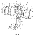
Fig. 1 is a perspective view of a clamshell type coupler and a latching mechanism of the invention in a first embodiment with the coupler in an uncoupled or open position. This figure further illustrates a pair of flanges or ferrules connected to the ends of respective fluid conveying members to be joined by the coupler, and an annular sleeve for sealing of the flanges/ferrules within the coupler; -
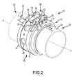
Fig. 2 is another perspective view of the embodiment ofFig. 1 showing the coupler placed in a coupled or closed position in which the flanges and sleeve are captured within the coupler thereby creating a fluid tight seal across the joined fluid conveying members; -
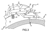
Fig. 3 is a greatly enlarged fragmentary perspective view of the coupler and the latching mechanism of the first embodiment ofFig. 1 illustrating additional details of the latching mechanism; -
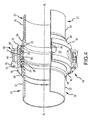
Fig. 4 is a fragmentary cross sectional view of the embodiment ofFig. 1 illustrating further details of the latching mechanism of the first embodiment, and the manner in which the coupler achieves a fluid tight seal across the facing ends of the fluid conveying members joined by the coupler; -
Fig. 5 is a perspective view of the clamshell type coupler and latching mechanism of the invention in a second embodiment with the coupler in the coupled or closed position; -
Fig. 6 is a greatly enlarged fragmentary perspective view of the coupler and the latching mechanism of the second embodiment illustrating additional details of the latching mechanism; -
Fig. 7 is a greatly enlarged fragmentary cross section taken along line 7-7 ofFig. 5 illustrating further details of the latching mechanism; -
Fig. 8 is a perspective view of the clamshell type coupler and latching mechanism of the invention in a third embodiment with the coupler in the coupled or closed position, and further illustrating a latch indicator used to verify a proper locked position for the latch mechanism, the latch indicator shown in an open position; -
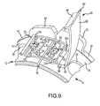
Fig. 9 is a greatly enlarged fragmentary perspective view of the coupler and the latching mechanism of the third embodiment illustrating additional details of the latching mechanism and latch indicator; -
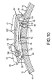
Fig. 10 is a greatly enlarged fragmentary cross section taken along line 10-10 ofFig. 8 illustrating further details of the latching mechanism and latch indicator of the third embodiment showing the latch indicator in a closed position; -
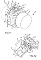
Fig. 11 is a perspective view of the clamshell type coupler and latching mechanism of the invention in a fourth embodiment with the coupler in the coupled or closed position; -
Fig. 12 is a greatly enlarged fragmentary perspective view of the coupler and the latching mechanism of the fourth embodiment illustrating additional details of the latching mechanism; -
Fig. 13 is a fragmentary cross section taken along line 13-13 ofFig. 11 illustrating further details of the latching mechanism; -
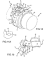
Fig. 14 is a perspective view of the clamshell type coupler and latching mechanism of the invention in a fifth embodiment with the coupler in the coupled or closed position; -
Fig. 14A is a greatly enlarged fragmentary view of a portion of a latch plate of the fifth embodiment illustrating the shape of an opening and adjacent slot for receiving a locking ball of a base plate; -
Fig. 15 is a greatly enlarged fragmentary perspective view of the coupler and the latching mechanism of the fifth embodiment illustrating additional details of the latching mechanism; -
Fig. 16 is a greatly enlarged fragmentary cross section taken along line 16-16 ofFig. 14 illustrating further details of the latching mechanism; -
Fig. 17 is a greatly enlarged fragmentary perspective view of the coupler a latching mechanism and latch indicator in a sixth embodiment, showing the latching mechanism in an unlocked position and the latch indicator in an open position; -
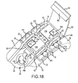
Fig. 18 is another greatly enlarged fragmentary perspective view of the coupler and the latching mechanism of the sixth embodiment, showing the latching mechanism in a locked position and the latch indicator remaining in the open position; -
Fig. 19 is a perspective view of the clamshell type coupler and latching mechanism of the sixth embodiment with the coupler in the coupled or closed position and the latch indicator in a closed position; and -
Fig. 20 is a greatly enlarged fragmentary cross section taken along line 20-20 ofFig. 19 illustrating further details of the latching mechanism. - Referring to the drawings, and particularly to
Figs. 1-4 , a threadless, clamshell type coupling assembly or coupler is illustrated in a first embodiment, and is generally indicated at 10. The coupling assembly comprises a pair ofcoupling halves 12 that are connected to one another alonghinge 14. Each of the coupling halves 12 terminate along respective longitudinally extending faces 15. These faces define the free ends of the coupling halves that are placed in a confronting position to close the coupling and to thereby secure confronting ends of thefluid conveying members 30. Alatching mechanism 40 is provided to positively and selectively lock the coupling halves to one another in a closed or coupled position. As shown, the coupling halves 12 are curved or arcuate in shape, and traverse an arc of approximately 180°. - The threadless clamshell type coupling assembly illustrated is especially adapted for use in fluid conveying applications, such as low pressure aircraft fuel systems. However, it shall be understood that the latching mechanisms described herein with respect to various preferred embodiments are not limited to any particular fluid conveying application within a disclosed combination of a coupling assembly and a latching mechanism.
- The
hinge 14 enables the coupling halves 12 to move relative to each other between a generally open or uncoupled position, such as shown inFig. 1 , and a generally closed or coupled position, such as shown inFig. 2 . Thehinge 14 may be the same as disclosed in the Applicant's priorUS Patent Nos. 8,075,024 or6,880,859 , these references being hereby incorporated herein for purposes of disclosing particular constructions for hinges used within clamshell type couplers. - The transverse ends or edges of the coupling halves 12 each include a
shoulder 16 interconnected by acentral web 18. The interior sides of the transverse ends each include a pair of closely spacedannular walls 20 defining a groove between the annular walls. Each of these grooves receives a portion of a bonding jumper orbonding wire 22. Eachbonding wire 22 is a piece of conductive material that extends continually around the coupler, and extends continuously across thehinge 14 and across thelatching mechanism 40. This continuous, electrically conductive bonding wire may also be the same as disclosed in the Applicant's priorUS Patents 8,075,024 or6,880,859 and these references being further incorporated herein for purposes of disclosing a particular construction for a bonding wire that may be used within the invention. - One or
more sight openings 26 may be formed in the coupling halves 12 to enable a user to view the connected relationship between the fluid conveyingmembers 30, and to specifically confirm that the abutting flanges orferrules 34 are properly joined to one another within the coupling assembly. Referring specifically toFig. 4 , thecoupling assembly 10 is configured to connect confronting ends of thefluid conveying members 30. As shown, eachfluid conveying member 30 includes fluid conveying elements in the form of a conduit ortube 32, with each fluid conveying member terminating with the flange orferrule 34. When the coupling assembly is fully closed or coupled, asleeve 37 spans between and resides over the distal ends of theferrules 34. Each of theferrules 34 includes an annular channel or groove 35 configured to receive an annular sealing member, such as an O-ring 28. Thesleeve 37 is cylindrical in shape, and includes a smoothinterior surface 39 that contacts the O-rings 28, thereby resulting in a seal created between the coupled sections of tubes. - In order to join the confronting ends of the
fluid conveying members 30, the O-rings 28 are first placed within theirrespective grooves 35, and the ends of the fluid conveying members are moved to a confronting position as shown such that thesleeve 37 is installed over both of the O-rings 28. The coupler is then positioned so that thesleeve 37 is located within theweb 18 of one of the coupling halves 12. The coupling halves are rotated relative to one another towards the closed or coupled position. Thesleeve 37 is sized in length to span or bridge the space between the end faces of theferrules 34 so that theinterior surface 39 of thesleeve 37 peripherally surrounds and seats against the O-rings 28 as shown. It shall be appreciated that the grooves orchannels 35 of eachferrule 34 are sufficiently sized to permit the annular sealing members or O-rings 28 to protrude radially beyond the outer surfaces of theferrules 34. In this manner, the O-rings can be adequately compressed against theinterior surface 39 of thesleeve 37 thereby establishing a fluid tight seal spanning across the facing ends of theferrules 34. Optionally, the outer surfaces of thesleeves 37 maybe roughened to enable a user to better grip the sleeve in the course of assembling thesleeve 37 over theferrules 34. -
Fig. 4 further illustrates that the coupling assembly results in joining of thefluid conveying members 30 generally along a longitudinal axis A-A. However, theFig. 4 also illustrates that the coupling assembly allows for some axial and angular adjustment between theferrules 34 thereby allowing theferrules 34 to be located anywhere between the maximum longitudinal extension of thesleeve 37, so long as the O-rings 28 are capable of making contact with theinterior surface 39 of thesleeve 37. Accordingly, theferrules 34 may be slightly spaced from one another as shown inFig. 4 , or the ferrules may be positioned so that the confronting faces 38 of the ferrules (seeFig. 1 ) make contact with one another within thesleeve 37. For angular adjustment between theferrules 34, the diameter of the O-rings 28 may determine the extent to which the fluid conveying members can angularly extend away from or depart from alignment with the longitudinal axis A- A, yet the O-rings 28 still capable of providing a proper sealed relationship. As can be appreciated, the larger the O-rings 28 used, the greater angular displacement that may be achieved with the coupling assembly in joining fluid conveying members yet still maintaining a sealed connection between the joined fluid conveying members. - As best seen in
Fig. 3 , alatching mechanism 40 is illustrated in a first embodiment of the invention. Thelatching mechanism 40 includes a pair of latching mounts orbrackets 42 that are disposed on therespective shoulders 16 of both coupling halves 12. The latching mounts 42 accommodate two functions; one function being to provide some lateral or transverse containment for the latch mechanism, thereby protecting the latch mechanism. The other function is to provide structure for mounting of elements or components of thelatch mechanism 40. With respect to this latter function or purpose, it is shown that thelatching mechanism 40 includes two major components, namely, acatch lever 44 and alatch plate 54 that are located between the latching mounts 42, and both of which are mounted to the latching mounts 42 byrespective pins spring 48 has one end secured to theweb 18, and the other end secured to aproximal end 47 of thecatch lever 44. In this arrangement, thecatch lever 44 is urged so that the catch lever is rotated in a position so that thedistal end 45 of the catch lever rotates towards theweb 18. Thelatch plate 54 extends across the small gap between thefaces 15 of the respective coupling halves 12. A distal end of thelatch plate 54 has acam opening 56 to receive a cam orextension 46 formed on thedistal end 45 of thecatch lever 44. As thedistal end 45 of thecatch lever 44 rotates toward theweb 18, theextension 46 is securely placed within theopening 56. The size of thespring 48 and its distance to the rotation point aboutpin 50 can be selected so that sufficient force is provided for placing the coupling assembly in a locked position preventing inadvertent removal of theextension 46 within theopening 56. Further, the particular shape of theextension 46 can be selected so that it best maintains a locked relationship with thelatch plate 54 when the coupling halves are fully rotated toward one another in a fully closed position. For example, the tip of theextension 46 may have a slight curvature or curl (not shown) that engages the interior surface of thelatch plate 54 facing theweb 18. In order to unlock the latching mechanism, the user places force against theproximal end 47 of thecatch lever 44 in a direction toward the web. Alternatively, the user may pull on thedistal end 45 with sufficient force to remove theextension 46 from within theopening 56. - Referring to
Figs. 5-7 , alatching mechanism 40 is illustrated in a second embodiment. A general principle of operation for this embodiment is the use one or more spring-loaded buttons that can be used to positively engage and lock the coupling assembly. Referring toFigs. 6 and7 , thelatching mechanism 40 includes a base or mountportion 64 mounted to a first coupling half and located between the respective latching mounts 42. Two extensions ortongues 60 extend circumferentially beyond theface 15 of the first coupling half towards the second coupling half. A latchinghole 62 is formed in each of theextensions 60 as shown. The second coupling half includes a latchinghousing 66 with a pair of latchingopenings 68 sized and oriented for receiving theextensions 60. Each of theopenings 68 communicate with abiased locking button 70 that may be manipulated by the user to lock and unlock the latching mechanism. Referring specifically toFig. 7 , one particular construction for thebiased locking button 70 and the latchinghousing 66 is shown, and which is similar to what is described in theUS Patent 6,694,578 . As illustrated, thelocking button 70 extends through anopening 71 formed on the upper surface of the latchinghousing 66. Apressure plate 78 is attached to the lower surface of thebutton 70. Abiased catch member 72 is mounted within and secured to thehousing 66. In the configuration shown inFig. 7 , thebiased catch member 72 acts as a leaf spring in order to provide a biased or spring-loaded catch to capture theextension 60. As a user depresses thebutton 70, thecatch member 72 rotates aboutinternal blocking pin 76 causing the distal end of thecatch member 72 to rise, allowing theextension 60 to be fully inserted within thehousing 66. Releasing thebutton 70 allows thecatch member 72 to rotate back to its normal, lowered position within thehousing 66. Thecatch member 72 has a flange orprotrusion 74 that is sized to fit within theopening 62. Accordingly, force applied to the coupling assembly to open the coupling assembly is prevented by theflange 74 retained within theopening 62. In order to unlock the latching mechanism, the user simply presses on thebutton 70 and pulls the coupling halves apart. Providing a redundant pair ofextensions 60 andcorresponding locking buttons 70 provides further assurance that the coupling assembly will not become inadvertently unlocked. - Referring to
Figs. 8-10 , another embodiment of thelatching mechanism 40 of the invention is illustrated. These figures also illustrate use of a secondary latch mechanism orlatch indicator 80. While some of the embodiments disclosed herein may not illustrate use of alatch indicator 80, it shall be understood that each of the embodiments may incorporate alatch indicator 80. Thelatch indicator 80 is not illustrated in some of the embodiments in order to simplify illustration of the various latchingmechanisms 40. In general, this embodiment involves the use of two redundant trapeze type latching arms for locking the coupling assembly. A first trapeze latch group includes aninner latching arm 92, shown in the form of a rigid wire that is rotatably mounted to a pair of inner hinge mounts 94 located on one of the coupling halves. A free end of theinner latching arm 92 is rotatably secured to aninner latching cam 96 located on the other coupling half. Theinner latching cam 96 itself is rotatably mounted about a pair of inner latching mounts 98 byinner latching pin 100. A second trapeze latch group includes the same general configuration as the first trapeze latch group, and this second group is mounted circumferentially around the first group. The second trapeze latch group more specifically includes a second outer latchingarm 102, also shown in the form of a rigid wire, rotatably mounted to a pair of outer hinge mounts 104 located on one of the coupling halves. A free end of theouter latching arm 102 is rotatably secured to anouter latching cam 106 located on the other coupling half. Theouter latching cam 106 is also rotatably mounted about a pair of outer latching mounts 108 by anouter latching pin 110. When the latching mechanism is placed in the unlocked position, the latchingcams Fig. 9 . In this relationship, the coupling halves are allowed to be spread apart a distance defined by the respective distances between the points of rotation of the latching cams (about therespective pins 100 and 110), and the location where the latching arms attached to the latching cams. This distance may be selected such that the coupling halves may be suitably spread apart from one another in an open position to enable thesleeve 37 andferrules 34 to be inserted within the interior of the coupling without undue difficulty. In order to lock the latching mechanism, the latchingcams web 18. A degree of rotation is provided so that the latching cams may be rotated beyond horizontal, thereby taking advantage of a locking arrangement in which additional force is required to reverse rotate the locking cams to an unlocked position. As also illustrated best inFig. 9 , the inner and outer latching arms each include respective pairs of spaced latching arm extensions that extend across the gap between the facing ends 15 of the coupling halves 12. These latching arm extensions can be defined as the straight sections of the latching arms that are oriented substantially parallel to one another and which extend in a direction to traverse the gap. As also shown in this preferred embodiment, the inner latching arm is disposed within an area bounded by the outer latching arm. This nested arrangement between the latching arms is a space saving configuration in which redundancy is provided by two elements for locking of the latching mechanism. Further,Fig. 9 illustrates a reverse mounting arrangement between the inner and outer latching arms in which one latching cam is located on both coupling halves. - For the secondary latch mechanism or
latch indicator 80, this indicator provides verification that the coupling assembly is properly secured in a closed or coupled position by thecorresponding latching mechanism 40. As shown, thelatch indicator 80 includes a mounting flange orbase 84 with a mountingpin 86 enabling thelatch indicator 80 to be rotated between an open position as shown inFig. 9 , and a closed position as shown inFig. 10 . Thelatch indicator 80 further includes abody 82 having a width that extends substantially across the gap between the opposing pairs of latching mounts 42. The free or distal end of thebody 82 includes acurved latching projection 88. This distal end also includes arelease tab 89. When thelatching mechanism 40 is placed in its locked position, the latch indicator may be moved to its closed position in order to confirm that the latching mechanism has been properly locked, and also to provide protection for the latch mechanism. Referring specifically toFig. 10 , thelatch indicator 80 is rotated downward such that the latchingprojection 88 is frictionally engaged around thelatch pin 90. Thelatch pin 90 is selectively positioned such that the latchingprojection 88 cannot be engaged with thelatch pin 90, unless thelatching mechanism 40 is properly locked, as defined with the coupling halves being positioned at a set location between one another. For example, if thelatching mechanism 40 is not properly locked, this will result in the coupling halves being spread apart too far from one another or too close to one another. In the first circumstance, when the user makes an attempt to close thelatch indicator 80, the latchingprojection 88 will not extend far enough to reach thelatch pin 90. In the second circumstance, when the user closes thelatch indicator 80, although the latchingprojection 88 may be positioned far enough to reach thelatch pin 90, the latchingprojection 88 will not adequately engage thelatch pin 90 allowing the latch indicator to be freely opened without resistance against the latch pin. When thelatching mechanism 40 is properly locked, thelatch indicator 80 can be closed resulting in contact of the latchingprojection 88 against thelatch pin 90, with an audible "click" indicating a proper closed position for the latch indicator. In general, thelatch indicator 80 therefore serves as both a visual and tactile indicator used to verify that the coupling assembly is properly installed and secured over the connected fluid conveying members. Preferably, the latch indicator may be constructed of a suitable material to prevent any chance of a spark gap occurrence, as may be required by the applicable regulations for which the latch mechanism is intended to be used. One example of material that can be used includes a thermoplastic organic polymer, such as polyetheretherketone (PEEK). Alternatively, thelatch indicator 80 could be constructed of a conductive metallic material. - Referring to
Figs. 11-13 , a fourth embodiment is illustrated for thelatch mechanism 40. This embodiment is characterized by asingle latching arm 120 rotatably mounted on apin 124 that traverses between adjacent latching mounts 42. The latchingarm 120 includes a central rod orcore 126, with a proximal end thereof having an opening to receive the mountingpin 124. Aretention spring 128 is placed over the distal end of thecentral rod 126, and resides between the proximal end of thecentral rod 126 and amovable bushing 130 mounted over thecentral rod 126 distally of thespring 128. Aspacer 132 is also placed over the distal end of thecentral rod 126, and resides distally of themovable bushing 130. A head or cap122 attaches to the distal end of therod 126. Themovable bushing 130 may be selectively slid proximally along thecentral rod 126, thereby compressing thespring 128. The normal, biased position of themovable bushing 130 is shown inFig. 12 , in which themovable bushing 130 abuts thespacer 132. Thespacer 132 defines a gap or space enabling the distal free end of the latching arm to be placed in a locked position. More specifically, alocking bracket 134 is mounted on the other coupling half as shown, thebracket 134 having a reverse "S" shape in cross-section. Abase portion 136 of the bracket is mounted to the web18 of the coupler. Theupper portion 138 of thebracket 134 includes aslot 140 for receiving thespacer 132 when the latchingarm 120 is rotated downward. First,movable bushing 130 is retracted, thereby generating an additional gap between the proximal end of thespacer 132 and the distal end of thebushing 130. Referring also toFig. 13 , after thespacer 132 has cleared theupper portion 138 of thebracket 134, the spacer is allowed to proceed further into theslot 140 that extends along the vertical portion of thebracket 134. At this position, themovable bushing 130 can be released, and thebushing 130 is therefore urged in contact against the vertical portion of thebracket 134, thereby locking the latching mechanism. As also shown inFig. 13 , themovable bushing 130 is sized so that it fits snugly within the gap between theupper portion 138 of thebracket 134 and the surface of theweb 18. In this configuration, the spring force provided by the retention spring128 and the size of themovable bushing 130 located in the gap provides for a reliable locking connection. In order to unlock the latching mechanism, force is applied to themovable bushing 132 to compress thespring 128, and the latching arm120 can be rotated away from thebracket 134 when thebushing 132 has been retracted enough to clear thebracket 134. - Referring to
Figs. 14-16 , thelatching mechanism 40 is illustrated in a fifth embodiment. This embodiment may be generally characterized as an over-center latching configuration in which two movable latching plates are simultaneously rotated over a stationary base plate and secured against the base plate to place the coupling assembly in a closed or coupled position. More specifically, referring especially toFig. 15 , thelatching mechanism 40 includes afirst latch plate 150 having a first end rotatably connected to one of the coupler halves by ahinge 156. Asecond latch plate 152 has a first end rotatably connected to the other coupling half by anotherhinge 156. The second ends of the first and second latch plates are rotatably connected to one another along anotherhinge 157. Referring also toFig. 14 , astationary base plate 154 is attached to a distal end of thecorresponding coupling half 12. As shown, the base plate may have a first end rotatably attached to yet anotherhinge 159 secured to the web18. A second end of thebase plate 154 rotatably attaches to the first end of thesecond latch plate 152. In an open position, the first ends of the first and second latch plates are separated from one another, thereby expanding the gap between the facing ends of the coupler halves. In order to close and lock the latching mechanism, the first ends of thelatch plates base plate 154.Figs. 14 and 15 illustrate the first and second latch plates in a partially folded orientation. Thesecond latch plate 152 further includes anopening 160, and thebase plate 154 further includes alocking ball 158 that aligns with theopening 160 such that when the first and second latch plates are fully rotated over thebase plate 154, the lockingball 158 is inserted within theopening 160. As can be appreciated, once the first and second latch plates have been fully rotated, the position of the lockingball 158 within theopening 160 prevents thelatch plates opening 160 can be provided so that, in order to align thelocking ball 158 with theopening 160, the coupler halves must be rotated slightly beyond an optimal closed position. Referring specifically to the greatly enlarged fragmentary plan view of the opening inFig. 14A , the head portion of the lockingball 158 is first received within theopening 160, and as pressure on the coupling halves is released, the neck or smaller diameter portion of the lockingball 158 travels within aslot 164 that communicates with theopening 160. In this configuration, the latching mechanism holds the coupler halves in an optimal closed or coupled position. An additional feature that may assist in maintaining the coupler halves in the closed position includes the provision of a key 162 located on the lateral side of one or both of themovable latch plates 150/152 and a corresponding keyway or slot 163 formed on the other movable latch plate. In the locked position of the latching mechanism, the key 162 andkeyway 163 align, thereby providing an additional element to prevent the latching mechanism from inadvertently opening. - Referring to
Figs. 17-20 , thelatching mechanism 40 is illustrated in a sixth embodiment. This embodiment can be generally characterized as including a pair of cassette connectors each having biased connector extensions for locking the facing ends of the coupler halves to one another. First referring toFig. 17 , thelatching mechanism 40 is illustrated in which two mirrorimage cassette connectors 180 are provided, one mounted to each end of the respective coupler halves. As shown, one or more mounting pins 181 are used to mount thecassette connectors 180 between the latching mounts 42. Each cassette connector has amain body portion 198 with aconnector extension 182 extending toward the opposingcassette connector 180. Themain body portion 198 further includes a receivingslot 186 and anopening 187 that communicates with the slot. Theopening 187 extends throughmain body portion 181 and terminates where theslot 186 is exposed.Fig. 18 illustrates the latching mechanism in a closed and locked position in which theconnector extensions 182 are inserted through the opposing receivingslots 186. Each of theconnector extensions 182 include aretention tab 184 that is sized to fit within a receivingslot 186. According to the views ofFigs. 17 and18 , the connector extensions182 extend from their correspondingbodies 198 in a slightly upward direction so that when thetabs 184 clear theopenings 187 and are placed in theslots 186, thetabs 184 haveproximal surfaces 194 that biasingly engage corresponding catch surfaces 196 of the slots186. In order to unlock the latching mechanism, both of theretention tabs 184 must be simultaneously pressed downward, so that thetabs 184 clear the catch surfaces196 of theslots 186 as the coupling halves are rotated away from one another. - In addition to the bonding wires that may be used to electrically couple the elements of the fluid conveying members and coupling assembly thereby preventing potential electrostatic buildup, the latching mechanisms may be provided with further conductive elements, shown in
Fig. 17 as abonding extension 190, abonding spring 188 connected to theextension 190, and aconductive insert 192 placed within theopening 26. Assuming the coupling halves are adequately conductive, it is not required to provide theinsert 192 however, theinsert 192 along with thebonding spring 188 andbonding extension 190 can in any event be used to further electrically tune the coupling assembly in order to optimally dissipate electrostatic charges. - According to methods of the invention, each of the latching mechanisms embodiments also include respective methods of interconnecting fluid conveying members and selectively sealing and closing a joint or connection between the fluid conveying members so that a fluid tight seal is achieved across the joint or connection. In general, the methods include providing a coupling assembly, such as a clamshell type coupler, and providing hardware configurations on the ends of the fluid conveying members to be joined, such as respective ferrules, sealing members (O-rings), and a sleeve extending between the ferrules. The methods further include capturing the ends of the fluid conveying members and hardware within the coupler, and rotating or translating the coupler to a closed position around the fluid conveying members so that the free ends of the coupling halves are aligned and are placed close to or in contact with one another. Further steps in the methods relate to the various embodiments of the latching mechanisms and the manner in which selective locking features are provided to positively and selectively lock and unlock the latching mechanisms.
- According to one method of the invention, a latching mechanism includes a catch lever that cooperates with a latch plate to selectively lock and unlock the latching mechanism. The catch lever is mounted on one of the coupling elements, and is biased to rotate in a manner to engage an opening in the latch plate. The latch plate is mounted on the other coupling element, and may also be rotatable to best align the latch plate with the catch lever, thereby locking the latching mechanism in place.
- According to another method of the invention, a latching mechanism includes at least one tongue or extension extends from a base mounted to one of the coupling elements, and a latching housing is mounted to the other coupling element, with an opening to receive the extension. The latching housing further includes a biased locking button communicating with the opening, enabling a user to selectively lock and unlock the extension within the opening thereby placing the latching mechanism in a corresponding locked or unlocked position. In one preferred embodiment, the method incorporates at least a pair of extensions received in corresponding openings of the latching housing.
- According to another method of the invention, a latching mechanism includes inner and outer latching arms that extend across the gap between the facing ends of coupling elements. Each of the latching arms are rotatably mounted to one of the coupling elements. A free or latching end of each of the latching arms is secured to the other coupling element in a locking cam configuration such that the latching arm can be moved between a first unlocked position to a second locked position that draws the ends of the coupling elements toward one another, thereby locking the latching mechanism. The locking cam configuration includes a latching cam secured to the latching arm, and the latching cam itself being rotatably mounted to the coupling element. According to one embodiment, the inner and outer latching arms are reversed mounted on the coupling elements, namely, the inner latching arm has its corresponding latching cam secured to one of the coupling elements, and the outer latching arm has its corresponding latching cam secured to the other coupling element. This interlocking mounting of the latching arms provides for redundancy in achieving a locked position for the latching mechanism.
- According to another method of the invention, a latching mechanism includes a latching arm rotatably mounted to one coupling element, and a bracket mounted to the other coupling element which receives the latching arm when the latching arm is rotated towards the bracket. The bracket includes a slot configured to receive the free or distal end of the latching arm. The latching arm includes a spring biased bushing that can be selectively slid or translated along a central rod of the latching arm. To lock the latching mechanism, the latching arm is rotated to engage the bracket in which the bushing is retracted along the central rod, enabling the distal end of the latching arm to be inserted within the slot of the bracket. The bushing is then released to make frictional engagement with a facing surface of the bracket. To unlock the latching mechanism, the bushing is again retracted, and the latching arm is rotated away from the bracket.
- According to another method of the invention, a latching mechanism includes first and second cooperating latch plates that are rotated simultaneously, and are then engaged with a base plate, thereby placing the latching mechanism in a locked position. The first and second latch plates each have a first end mounted to respective ends of the coupling elements. The second ends of the first and second latch plates are rotatably connected to one another. Upon rotation of the first and second latch plates towards the base plate, this results in drawing the ends of the coupling elements toward one another. A locking feature is provided to maintain the latching mechanism in a locked position. According to a preferred embodiment, the locking feature includes a locking ball mounted to and extending from the base plate, and a locking opening or slot formed on the first or second latch plate that receives the locking ball when the first and second latch plates have been rotated towards the base plate. To unlock the latching mechanism, force is applied to the joined ends of the first and second latch plates to overcome the frictional connection between the locking ball and locking opening/slot.
- According to another method of the invention, a latching mechanism includes a pair of cooperating cassette connectors, one connector mounted on each end of the coupling elements to be joined. According to a preferred embodiment, each cassette connector includes a connector extension with a tab formed on the free or distal end of the extension. Each connector further includes a receiving opening and receiving slot formed in the connector and positioned adjacent the connector extension. The receiving slot is a continuation of the receiving opening with a surface of the cassette body removed to expose the slot. To place the latching mechanism in a locked position, the connector extensions are inserted within the facing receiving openings of the other cassette connector, and the tabs snap into engagement with catch surfaces of the receiving slots. The connector extensions are oriented so they can be inserted within the receiving openings when the coupling elements are positioned close to or in contact with one another. The connector extensions rotate upwards or radially outward away from the latching mechanism once the tabs clear the openings and enter receiving slots, thereby generating an audible/tactile "click". To unlock the latching mechanism, the tabs are pressed downward, enabling the tabs to clear the corresponding catch surfaces. The coupling elements may then be separated from one another as the connector extensions are removed from within the receiving slots and openings.
- Each of the methods of the invention may further include a latch indicator feature in which a latch indicator element may be used in conjunction with the latching assemblies to verify that the coupling assembly is properly installed and secured over the fluid conveying members. In a preferred embodiment, the latch indicator may include a rotatable latching body having a latching projection formed on the free or distal end thereof. The latching projection frictionally engages and attaches to a latch pin when the latching body is rotated in a closed position. If the latching projection of the latching body is unable to reach the latch pin, this indicates that the coupling elements have not been drawn close enough to one another, which may be an indication that there is some misalignment between the fluid conveying members. If the latching projection is able to reach the latch pin, but extends beyond the latch pin such that there is no frictional engagement with the latch pin, this indicates that the coupling elements have been drawn too close to one another, and again this may indicate misalignment between the fluid conveying members. Upon occurrence of an improper closing of the latching projection over the latch pin, a user can inspect the fluid conveying members and the coupling assembly to troubleshoot the reason why the connection or joint has not been properly made.
- The coupling assembly described herein as a number of advantages. Each of the embodiments of the respective latching assemblies or mechanisms provides structural redundancy for selectively locking and unlocking the latching assemblies. This structural redundancy is provided within simple yet robust components that provide reliable and easy-to-use ways to lock and unlock the latching assemblies. The latching mechanisms employ bonding elements that achieve the necessary conductivity across the coupling assembly to eliminate the possibility of build-up of electrostatic charges. The addition of a latch indicator ensures that the coupling assembly is properly assembled and that the latching mechanism is properly installed over the ends of the fluid conveying members, thereby preventing inadvertent leakage of fluid. The latch indicator also serves to protect the latching mechanism.
- The invention has been set forth with respect to preferred embodiments of both latching mechanisms and methods related to installing and using the latching mechanisms. The disclosure of the preferred embodiments is not intended to restrict or otherwise limit the scope of the claimed invention. Therefore, it should be understood that the details disclosed in the preferred embodiments can be modified within the scope of the appended claims. Further, the preferred embodiments are illustrative, and no single feature or element is essential to all possible combinations that may be claimed herein.
Claims (16)
- A latching mechanism for selectively locking and unlocking a coupling used to interconnect ends of two fluid conveying members, said mechanism comprising:a catch lever rotatably mounted to a first coupling member of said coupling, said catch lever having a distal end and an extension protruding from said distal end;a spring communicating with said catch lever for biasing said catch lever and urging said distal end of said catch lever toward the first coupling member;a latch plate rotatably mounted to a second coupling member of said coupling, said latch plate extending across a gap between facing surfaces of said first and second coupling members when said coupling is placed in a closed position about said fluid conveying members; andsaid latch plate further including an opening formed therein for receiving said extension of said catch lever when said latching mechanism is placed in a locked position, and said latching mechanism placed in an unlocked position, when said extension is removed from within said opening.
- A latching mechanism, as claimed in claim 1, wherein:said spring is located adjacent a proximal end of said catch lever and connected to said catch lever, and wherein force applied to said proximal end of said catch lever displaces said distal end of said catch lever away from said latch plate.
- A latching mechanism, as claimed in claim 1 or 2, wherein:said catch lever and said latch plate are rotatably mounted to respective pairs of latching mounts extending radially away from outer surfaces of said first and second coupling members.
- A latching mechanism, as claimed in claim 2, wherein:said spring interconnects said proximal end of said catch lever to an outer surface of said first coupling member.
- A latching mechanism, as claimed in claim 3, wherein:said latch plate is rotatable about a hinge pin extending between one pair of said respective pairs of latching mounts, and said opening in said latch plate is aligned for receiving said extension of said catch lever.
- A latching mechanism, as claimed in anyone of the preceding claims, wherein:said catch lever is rotatable about a hinge pin extending between one pair of said respective pairs of latching mounts, and said extension of said catch lever is aligned for placement within said opening in said latch plate.
- A latching mechanism, as claimed in anyone of the preceding claims, further including:a latch indicator having a proximal end rotatably mounted to one of said coupling members, and a distal end having a latching projection for engaging a latch pin fixedly mounted to the other of said coupling members, said latch indicator oriented to cover at least a portion of said catch lever and said latch plate when said latch indicator is rotated to a closed position in which said latching projection engages said latch pin.
- A latching mechanism, as claimed in claim 7, wherein:said latch pin is attached between one pair of said respective pairs of latching mounts.
- A latching mechanism, as claimed in claim 7, wherein:said latch indicator further includes a release tab formed on said distal end thereof.
- A method of selectively locking and unlocking a latch mechanism of a coupling used to interconnect facing ends of two fluid conveying members, said method comprising:providing a latch mechanism including (i) a catch lever rotatably mounted to a first coupling member of said coupling, said catch lever having a distal end and an extension protruding from said distal end; (ii) a spring communicating with said catch lever for biasing said catch lever and urging said distal end of said catch lever toward the first coupling member; (iii) a latch plate rotatably mounted to a second coupling member of said coupling;placing the ends of the two fluid conveying members within said coupling;closing said coupling about the ends of the two fluid conveying members to thereby orient said coupling in a closed position;rotating said latch plate to extend across a gap between facing surfaces of said ends of said first and second coupling members when said coupling is placed in the closed position about said fluid conveying members;manipulating said catch lever to place said extension of said catch lever within an opening formed in said catch plate thereby resulting in said latching mechanism being placed in a locked position; andfurther manipulating said catch lever to remove said extension of said catch lever from within said opening of said catch plate thereby resulting in said latching mechanism being placed in an unlocked position.
- A latching mechanism for selectively locking and unlocking a coupling used to interconnect ends of two fluid conveying members, said coupling having first and second coupling members, said latching mechanism comprising:a first cassette connector mounted to said first coupling member, said first cassette connector having a main body, an opening, a receiving slot communicating with said opening, and a connector extension extending away from said main body adjacent said opening;a second cassette connector mounted to said second coupling member, said first cassette connector having a main body, an opening, a receiving slot communicating with said opening, and a connector extension extending away from said main body adjacent said opening; andwherein when said first and second coupling members are placed in a closed position, said connector extensions each have distal ends that extend toward an opposing cassette connector and aligned with the opening of the opposing cassette connector, such that placing the latching mechanism in a locked position includes inserting the distal ends of the connector extensions through the corresponding openings and locating the distal ends of the connector extensions within the corresponding slots of the cassette connectors, and wherein placing the latching mechanism in an unlocked position includes depressing the distal ends of said connector extensions and pulling the first and second coupling members apart from one another, thereby removing the connector extensions from within the corresponding slots and openings of the respective cassette connectors.
- A latching mechanism, as claimed in claim 11, wherein:said distal ends of said connector extensions each include respective tabs, said tabs being frictionally engaged and held within said slots by contact between respective proximal surfaces of said tabs and respective catch surfaces of said cassette connectors.
- A latching mechanism, as claimed in claim 11 or 12, wherein:said connector extensions are oriented such that when placed through said openings of said cassette connectors, said connector extensions are biased against an internal surface defining said opening, resulting in a tactile indication after said distal ends clear said openings and are located in said slots.
- A latching mechanism, as claimed in anyone of claims 11 to 13, further including:a latch indicator having a proximal end rotatably mounted to one of said coupling members, and a distal end having a latching projection for engaging a latch pin fixedly mounted to the other of said coupling members, said latch indicator oriented to cover at least a portion of said catch lever and said latch plate when said latch indicator is rotated to a closed position in which said latching projection engages said latch pin.
- A latching mechanism, as claimed in claim 14, wherein:said latch pin is attached between one pair of said respective pairs of latching mounts.
- A latching mechanism, as claimed in claim 14 or claim 15, wherein:said latch indicator further includes a release tab formed on said distal end thereof.
Applications Claiming Priority (1)
| Application Number | Priority Date | Filing Date | Title |
|---|---|---|---|
| US14/052,476 US9261211B2 (en) | 2013-10-11 | 2013-10-11 | Latching mechanisms for clamshell type couplers |
Publications (2)
| Publication Number | Publication Date |
|---|---|
| EP2889524A2 true EP2889524A2 (en) | 2015-07-01 |
| EP2889524A3 EP2889524A3 (en) | 2015-09-30 |
Family
ID=51660387
Family Applications (1)
| Application Number | Title | Priority Date | Filing Date |
|---|---|---|---|
| EP14188043.5A Withdrawn EP2889524A3 (en) | 2013-10-11 | 2014-10-08 | Latching mechanism for clamshell type couplers |
Country Status (5)
| Country | Link |
|---|---|
| US (1) | US9261211B2 (en) |
| EP (1) | EP2889524A3 (en) |
| CN (1) | CN104728542B (en) |
| BR (1) | BR102014025008A2 (en) |
| CA (1) | CA2866925A1 (en) |
Cited By (1)
| Publication number | Priority date | Publication date | Assignee | Title |
|---|---|---|---|---|
| US11067211B2 (en) | 2016-03-17 | 2021-07-20 | Eaton Intelligent Power Limited | Aircraft fluid line coupling assembly for releasably interconnecting fluid conveying members |
Families Citing this family (27)
| Publication number | Priority date | Publication date | Assignee | Title |
|---|---|---|---|---|
| GB201506938D0 (en) * | 2015-04-23 | 2015-06-10 | Sentergy Ltd | Connection Mechanism |
| CN105114721A (en) * | 2015-09-07 | 2015-12-02 | 江苏祥生新能源科技有限公司 | High-molecular modified fast joint for downhole steel wire skeleton clad pipe |
| CN105909656A (en) * | 2016-06-25 | 2016-08-31 | 安徽工程大学机电学院 | Half nut and application method thereof |
| US10512218B2 (en) * | 2016-08-25 | 2019-12-24 | Bruce Fullerton | Mower having collection system with quick connect vacuum hose adapter |
| FR3062689B1 (en) * | 2017-02-03 | 2020-02-21 | Airbus Operations | COLLAR FOR FIXING A DUCT ON A SUPPORT. |
| FR3066648B1 (en) * | 2017-05-19 | 2019-06-14 | Amphenol - Air Lb | DEVICE FOR MAINTAINING AT LEAST ONE ELECTRICALLY CONDUCTIVE PIPE ON AN ELECTRIC CONDUCTIVE STRUCTURE |
| US11009159B2 (en) * | 2017-09-28 | 2021-05-18 | AdelWiggins Group, a Division of Transdigm, Inc. | Visual and tactile latch indicator for a fuel system coupling |
| US11692651B2 (en) * | 2017-12-13 | 2023-07-04 | Eaton Intelligent Power Limited | Coupler with non-metallic conductive gasket |
| US11519538B2 (en) * | 2018-08-02 | 2022-12-06 | The Boeing Company | Coupling assembly to connect first and second conduits |
| US10651572B1 (en) * | 2019-06-10 | 2020-05-12 | Meter Technology Werks, LLC | Bonding jumper system |
| JP7372075B2 (en) * | 2019-08-07 | 2023-10-31 | 日本ピラー工業株式会社 | Connecting member |
| JP7281362B2 (en) * | 2019-08-07 | 2023-05-25 | 日本ピラー工業株式会社 | connecting member |
| EP4028684B1 (en) * | 2019-09-09 | 2025-12-17 | Entegris, Inc. | Electrostatic discharge mitigation device |
| CN110529678B (en) * | 2019-09-28 | 2024-05-10 | 温州英凯隆精密科技有限公司 | Vacuum aluminum clamp |
| DE102019126484A1 (en) * | 2019-10-01 | 2021-04-01 | Norma Germany Gmbh | Profile clamp with locking tab |
| US11401960B1 (en) | 2019-11-07 | 2022-08-02 | Frank Richard Markusic | Clamping device |
| EP3875825A1 (en) * | 2020-03-02 | 2021-09-08 | Husqvarna Ab | Connector for a pump |
| US11608917B2 (en) * | 2020-03-09 | 2023-03-21 | AdelWiggins Group, a Division of Transdigm Inc. | Non-metallic fluid coupling |
| US11873161B2 (en) * | 2020-04-30 | 2024-01-16 | Rubbermaid Commercial Products Llc | Waste receptacles |
| US12269147B1 (en) * | 2020-07-21 | 2025-04-08 | Wilson Aerospace L.L.C. | Articulated reaction gear locking feature |
| CN112459082B (en) * | 2020-11-30 | 2022-02-08 | 四川仟坤建设集团有限责任公司 | Foundation pit slope collapse prevention structure and building method thereof |
| CN113067297B (en) * | 2021-03-05 | 2022-05-20 | 佛山市有为科技有限公司 | Light gauge steel structure convenient to spool is fixed |
| EP4112988A1 (en) * | 2021-06-28 | 2023-01-04 | Goodrich Corporation | Clamp assembly |
| US12116076B1 (en) * | 2021-09-10 | 2024-10-15 | Delta Enterprise Corp. | Standing board for attachment to a stroller |
| US20240175526A1 (en) * | 2022-11-28 | 2024-05-30 | Eaton Intelligent Power Limited | Coupling assembly, coupling system and links |
| CN116717643B (en) * | 2023-07-13 | 2026-01-06 | 中建二局安装工程有限公司 | A plug-in connection structure |
| CN121184667B (en) * | 2025-11-27 | 2026-02-03 | 龙岩学院 | New energy automobile cooling pipeline connects |
Citations (3)
| Publication number | Priority date | Publication date | Assignee | Title |
|---|---|---|---|---|
| US6694578B1 (en) | 2003-05-15 | 2004-02-24 | Kimberly A. Nicoll | Child safety belt buckle locking mechanism |
| US6880859B2 (en) | 2003-07-31 | 2005-04-19 | Stanley Aviation Corporation | Conduit coupling assembly |
| US8075024B2 (en) | 2008-06-30 | 2011-12-13 | Eaton Corporation | Coupling assembly |
Family Cites Families (56)
| Publication number | Priority date | Publication date | Assignee | Title |
|---|---|---|---|---|
| US3157932A (en) | 1963-08-07 | 1964-11-24 | Gilbert M Kyrias | Quick release clamp |
| US3434191A (en) | 1968-03-12 | 1969-03-25 | Tri State Oil Tools Inc | Apparatus for protecting well pipe |
| US3776579A (en) | 1971-03-11 | 1973-12-04 | Stanley Aviation Corp | Coupling assemblies |
| US4008937A (en) | 1974-09-20 | 1977-02-22 | Stanley Aviation Corporation | Coupling assembly |
| US4311248A (en) | 1974-11-04 | 1982-01-19 | Construction Forms, Inc. | High pressure coupling apparatus |
| US4123095A (en) | 1977-06-30 | 1978-10-31 | Hansted Corporation | Pipe clamp having an overcenter toggle |
| US4249786A (en) | 1978-11-03 | 1981-02-10 | Hydraflow Supply, Inc. | Flexible coupling |
| DE2849880C3 (en) | 1978-11-17 | 1981-09-10 | Karl Ing.(Grad.) 4040 Neuss Weinhold | Device for connecting hose or pipe ends |
| US4438958A (en) | 1980-01-17 | 1984-03-27 | Cenzo Herbert A De | Clam-shell coupling for joining beaded tubes |
| US4346428A (en) | 1980-06-05 | 1982-08-24 | Stanley Aviation Corp. | Coupling assembly with bonding jumper |
| US4358879A (en) | 1980-12-01 | 1982-11-16 | General Motors Corporation | Seat belt buckle |
| US4368563A (en) | 1981-07-13 | 1983-01-18 | Allied Corporation | Seat belt buckle with plastic cover |
| US4473369A (en) | 1982-01-11 | 1984-09-25 | Baxter Travenol Laboratories, Inc. | Continuous ambulatory peritoneal dialysis clamping system |
| US4432759A (en) | 1982-04-26 | 1984-02-21 | Abbott Laboratories | Connecting device for medical liquid containers |
| JPS6335611Y2 (en) * | 1984-10-23 | 1988-09-21 | ||
| US4697830A (en) | 1984-12-31 | 1987-10-06 | Petro-Tube, Inc. | Stabbing guide |
| DE3662812D1 (en) | 1985-05-11 | 1989-05-18 | Niigata Engineering Co Ltd | Quick release coupling device |
| US4804208A (en) | 1986-08-11 | 1989-02-14 | The Kendall Company | Manifold coupling assembly |
| US4955115A (en) * | 1988-07-11 | 1990-09-11 | Kabushiki Kaisha Tokai-Rika-Denki-Seisakusho | Buckle device |
| US4881760A (en) | 1988-11-07 | 1989-11-21 | Stanley Aviation Corporation | Conduit coupling device with redundancy features |
| FR2642814B1 (en) | 1989-02-08 | 1991-05-10 | Labinal | RING OF CLOSING OF RINGS |
| GB9000191D0 (en) | 1990-01-04 | 1990-03-07 | Legge Philip | Scaffold couplers |
| US5123677A (en) | 1990-05-31 | 1992-06-23 | Swagelok-Quick Connect Co. | All plastic quick-connect coupling |
| US5188400A (en) | 1991-09-17 | 1993-02-23 | Stanley Aviation Corporation | Spring loaded coupling with positive spring latch |
| US5208953A (en) | 1991-11-26 | 1993-05-11 | Trw Vehicle Safety Systems Inc. | Seat belt buckle having pivotal lever |
| US5257439A (en) * | 1992-05-11 | 1993-11-02 | Leblanc Lester A | Quick release adjustable dental band clamp |
| US5269572A (en) * | 1992-08-28 | 1993-12-14 | Gold Star Manufacturing, Inc. | Apparatus and method for coupling elongated members |
| US5293669A (en) | 1992-12-11 | 1994-03-15 | Gregory Sampson | Multi-use fastener system |
| US5385373A (en) | 1993-03-22 | 1995-01-31 | Cummins Engine Company, Inc. | Tamper-evident, self-locking cover for mechanical connections and related objects |
| US5398679A (en) | 1993-09-13 | 1995-03-21 | Freed; M. Simon | Hinged endotracheal tube holder having both a safety clamp and a securing clamp |
| US5524672A (en) | 1994-03-22 | 1996-06-11 | Mosing; Donald E. | Casing thread protector |
| CA2184656A1 (en) | 1995-09-05 | 1997-03-06 | Chubu Electric Power Company, Inc. | Clamp for overhead line and method of attachment thereof |
| US5620210A (en) | 1995-10-24 | 1997-04-15 | Stanley Aviation Corporation | Fluid conduit coupling |
| GB9609642D0 (en) | 1996-05-09 | 1996-07-10 | Legge Philip | Couplers |
| DE19639324C2 (en) * | 1996-09-25 | 1998-12-03 | Daimler Benz Ag | Pipe clamp with a tightening cap screw |
| CN2265465Y (en) * | 1996-09-27 | 1997-10-22 | 嵇玉海 | Locking type connector for pipe line |
| DE19735491C1 (en) * | 1997-08-16 | 1998-07-16 | Rasmussen Gmbh | Coupling device for use with hose |
| US6361523B1 (en) | 1998-03-27 | 2002-03-26 | Venetec International, Inc. | Anchoring system for a medical article |
| US6148924A (en) | 1998-11-10 | 2000-11-21 | Oil & Gas Rental Services, Inc. | Method and apparatus for the disassembly of drill pipe |
| DE19907412C2 (en) | 1999-02-20 | 2000-12-21 | Karl Weinhold | Coupling for steel spiral hoses |
| DE10024834A1 (en) | 2000-05-19 | 2001-11-29 | Fr Jacob Soehne Gmbh & Co | Tension ring |
| DE10057304A1 (en) | 2000-11-17 | 2002-05-23 | Putzmeister Ag | Pipe coupling comprises two shells around circular opening for pipe, external link, support block, closure mechanism, closure hook and swivel axle. |
| US6523866B2 (en) | 2001-06-06 | 2003-02-25 | Peter Lin | Constant tension clamping device for flanged connections |
| GB2396678B (en) | 2002-12-23 | 2006-08-23 | Taylor Kerr | Apparatus for repairing an underwater pipe |
| DE10304074B3 (en) * | 2003-01-31 | 2004-02-05 | A. Raymond & Cie | Removable insertion connection for high-pressure line has locking elements consisting of two half shells |
| CN2615472Y (en) * | 2003-03-24 | 2004-05-12 | 杨浤源 | Water pipe connection component structure |
| US6971682B2 (en) | 2003-04-15 | 2005-12-06 | Adel Wiggins Group, Transdigm, Inc. | Coupling assembly |
| US20050248098A1 (en) | 2004-04-27 | 2005-11-10 | Sisk David E | Gasket for a coupler upon a rail car, tank trailer, or related means |
| US7014225B1 (en) | 2004-09-07 | 2006-03-21 | Viking Plastics, Inc. | Snap connector for the coupling of pipes |
| US7290805B2 (en) | 2005-12-19 | 2007-11-06 | Highlight Tech. Corp. | Pipe clip |
| US20090096209A1 (en) | 2007-10-10 | 2009-04-16 | Transdigm, Inc., | Flexible, self-bonding coupling assembly |
| FR2923888B1 (en) | 2007-11-15 | 2014-01-17 | Legris Sa | DEVICE FOR RAPID CONNECTION OF A TUBE WITH SAFETY RING |
| JP5103249B2 (en) | 2008-04-02 | 2012-12-19 | 株式会社ニフコ | Pipe joint cover |
| US8201852B2 (en) | 2009-06-26 | 2012-06-19 | Ultraflo Corporation | Pipe coupler and gasket with positive retention and sealing capability |
| US8220113B2 (en) | 2010-11-19 | 2012-07-17 | Hitco, Ltd. | Smart clamp device for connecting tubing |
| CN103115206A (en) * | 2013-03-05 | 2013-05-22 | 葛文宇 | Female-male buckle hoop connection method for pipeline |
-
2013
- 2013-10-11 US US14/052,476 patent/US9261211B2/en active Active
-
2014
- 2014-10-07 BR BR102014025008A patent/BR102014025008A2/en not_active Application Discontinuation
- 2014-10-08 EP EP14188043.5A patent/EP2889524A3/en not_active Withdrawn
- 2014-10-10 CA CA 2866925 patent/CA2866925A1/en not_active Abandoned
- 2014-10-10 CN CN201410531832.6A patent/CN104728542B/en not_active Expired - Fee Related
Patent Citations (3)
| Publication number | Priority date | Publication date | Assignee | Title |
|---|---|---|---|---|
| US6694578B1 (en) | 2003-05-15 | 2004-02-24 | Kimberly A. Nicoll | Child safety belt buckle locking mechanism |
| US6880859B2 (en) | 2003-07-31 | 2005-04-19 | Stanley Aviation Corporation | Conduit coupling assembly |
| US8075024B2 (en) | 2008-06-30 | 2011-12-13 | Eaton Corporation | Coupling assembly |
Cited By (1)
| Publication number | Priority date | Publication date | Assignee | Title |
|---|---|---|---|---|
| US11067211B2 (en) | 2016-03-17 | 2021-07-20 | Eaton Intelligent Power Limited | Aircraft fluid line coupling assembly for releasably interconnecting fluid conveying members |
Also Published As
| Publication number | Publication date |
|---|---|
| US9261211B2 (en) | 2016-02-16 |
| CA2866925A1 (en) | 2015-04-11 |
| BR102014025008A2 (en) | 2015-10-06 |
| EP2889524A3 (en) | 2015-09-30 |
| CN104728542A (en) | 2015-06-24 |
| CN104728542B (en) | 2018-04-03 |
| US20150102600A1 (en) | 2015-04-16 |
Similar Documents
| Publication | Publication Date | Title |
|---|---|---|
| US9261211B2 (en) | Latching mechanisms for clamshell type couplers | |
| US12429152B2 (en) | Tubular connector | |
| US6776638B2 (en) | Breakaway locking connector | |
| US8075024B2 (en) | Coupling assembly | |
| JP6131183B2 (en) | Connector assembly | |
| US6880859B2 (en) | Conduit coupling assembly | |
| EP0679829A1 (en) | Coupling apparatus | |
| CN103174894A (en) | Connector for detachable connection of two fluid channels | |
| CN103915737A (en) | Electrical connectors with automatic engagement | |
| GB2346661A (en) | Quick connect-disconnect coupling with locking cams operated by levers | |
| US7086886B2 (en) | Reinforced locking connector | |
| WO2014143501A1 (en) | Concentric slide clamshell coupler | |
| CN114294499A (en) | Fluid connector system | |
| US7331827B2 (en) | Electrical connector with an anti-splay ferrule | |
| US20120208390A1 (en) | Connector assembly and a connector part thereof | |
| WO2015150341A1 (en) | Coupling device and connecting device |
Legal Events
| Date | Code | Title | Description |
|---|---|---|---|
| PUAI | Public reference made under article 153(3) epc to a published international application that has entered the european phase |
Free format text: ORIGINAL CODE: 0009012 |
|
| 17P | Request for examination filed |
Effective date: 20141008 |
|
| AK | Designated contracting states |
Kind code of ref document: A2 Designated state(s): AL AT BE BG CH CY CZ DE DK EE ES FI FR GB GR HR HU IE IS IT LI LT LU LV MC MK MT NL NO PL PT RO RS SE SI SK SM TR |
|
| AX | Request for extension of the european patent |
Extension state: BA ME |
|
| RIN1 | Information on inventor provided before grant (corrected) |
Inventor name: ADKINS, CHRIST T. Inventor name: KOTTOMEIER, THOMAS ALAN Inventor name: CAUDILL, JAY MACK Inventor name: PHANEUF, KENNETH G. Inventor name: BREAY, CLIFTON PAUL Inventor name: TABER, LANE CHARLES Inventor name: RITTER, MICHAEL ALAN Inventor name: SCHOOLEY, NICHOLAS CLANCY Inventor name: STATLER, RICHARD LOWELL Inventor name: WEST, JOSEPH GEORGE Inventor name: MARETICH, DAVID ETHAN Inventor name: NINNESS, AMY LYNN |
|
| PUAL | Search report despatched |
Free format text: ORIGINAL CODE: 0009013 |
|
| AK | Designated contracting states |
Kind code of ref document: A3 Designated state(s): AL AT BE BG CH CY CZ DE DK EE ES FI FR GB GR HR HU IE IS IT LI LT LU LV MC MK MT NL NO PL PT RO RS SE SI SK SM TR |
|
| AX | Request for extension of the european patent |
Extension state: BA ME |
|
| RIC1 | Information provided on ipc code assigned before grant |
Ipc: F16L 25/01 20060101AFI20150827BHEP |
|
| R17P | Request for examination filed (corrected) |
Effective date: 20160330 |
|
| RBV | Designated contracting states (corrected) |
Designated state(s): AL AT BE BG CH CY CZ DE DK EE ES FI FR GB GR HR HU IE IS IT LI LT LU LV MC MK MT NL NO PL PT RO RS SE SI SK SM TR |
|
| STAA | Information on the status of an ep patent application or granted ep patent |
Free format text: STATUS: THE APPLICATION HAS BEEN WITHDRAWN |
|
| 18W | Application withdrawn |
Effective date: 20180205 |