EP2889394A2 - Cast steel for construction equipment bucket parts and parts for construction equipment bucket comprising the same - Google Patents
Cast steel for construction equipment bucket parts and parts for construction equipment bucket comprising the same Download PDFInfo
- Publication number
- EP2889394A2 EP2889394A2 EP14181315.4A EP14181315A EP2889394A2 EP 2889394 A2 EP2889394 A2 EP 2889394A2 EP 14181315 A EP14181315 A EP 14181315A EP 2889394 A2 EP2889394 A2 EP 2889394A2
- Authority
- EP
- European Patent Office
- Prior art keywords
- carbide
- cast steel
- construction equipment
- parts
- equipment bucket
- Prior art date
- Legal status (The legal status is an assumption and is not a legal conclusion. Google has not performed a legal analysis and makes no representation as to the accuracy of the status listed.)
- Granted
Links
Images
Classifications
-
- E—FIXED CONSTRUCTIONS
- E02—HYDRAULIC ENGINEERING; FOUNDATIONS; SOIL SHIFTING
- E02F—DREDGING; SOIL-SHIFTING
- E02F9/00—Component parts of dredgers or soil-shifting machines, not restricted to one of the kinds covered by groups E02F3/00 - E02F7/00
- E02F9/28—Small metalwork for digging elements, e.g. teeth scraper bits
- E02F9/2808—Teeth
- E02F9/285—Teeth characterised by the material used
-
- C—CHEMISTRY; METALLURGY
- C21—METALLURGY OF IRON
- C21D—MODIFYING THE PHYSICAL STRUCTURE OF FERROUS METALS; GENERAL DEVICES FOR HEAT TREATMENT OF FERROUS OR NON-FERROUS METALS OR ALLOYS; MAKING METAL MALLEABLE, e.g. BY DECARBURISATION OR TEMPERING
- C21D6/00—Heat treatment of ferrous alloys
- C21D6/004—Heat treatment of ferrous alloys containing Cr and Ni
-
- C—CHEMISTRY; METALLURGY
- C21—METALLURGY OF IRON
- C21D—MODIFYING THE PHYSICAL STRUCTURE OF FERROUS METALS; GENERAL DEVICES FOR HEAT TREATMENT OF FERROUS OR NON-FERROUS METALS OR ALLOYS; MAKING METAL MALLEABLE, e.g. BY DECARBURISATION OR TEMPERING
- C21D6/00—Heat treatment of ferrous alloys
- C21D6/008—Heat treatment of ferrous alloys containing Si
-
- C—CHEMISTRY; METALLURGY
- C21—METALLURGY OF IRON
- C21D—MODIFYING THE PHYSICAL STRUCTURE OF FERROUS METALS; GENERAL DEVICES FOR HEAT TREATMENT OF FERROUS OR NON-FERROUS METALS OR ALLOYS; MAKING METAL MALLEABLE, e.g. BY DECARBURISATION OR TEMPERING
- C21D6/00—Heat treatment of ferrous alloys
- C21D6/02—Hardening by precipitation
-
- C—CHEMISTRY; METALLURGY
- C21—METALLURGY OF IRON
- C21D—MODIFYING THE PHYSICAL STRUCTURE OF FERROUS METALS; GENERAL DEVICES FOR HEAT TREATMENT OF FERROUS OR NON-FERROUS METALS OR ALLOYS; MAKING METAL MALLEABLE, e.g. BY DECARBURISATION OR TEMPERING
- C21D9/00—Heat treatment, e.g. annealing, hardening, quenching or tempering, adapted for particular articles; Furnaces therefor
- C21D9/0068—Heat treatment, e.g. annealing, hardening, quenching or tempering, adapted for particular articles; Furnaces therefor for particular articles not mentioned below
-
- C—CHEMISTRY; METALLURGY
- C22—METALLURGY; FERROUS OR NON-FERROUS ALLOYS; TREATMENT OF ALLOYS OR NON-FERROUS METALS
- C22C—ALLOYS
- C22C38/00—Ferrous alloys, e.g. steel alloys
-
- C—CHEMISTRY; METALLURGY
- C22—METALLURGY; FERROUS OR NON-FERROUS ALLOYS; TREATMENT OF ALLOYS OR NON-FERROUS METALS
- C22C—ALLOYS
- C22C38/00—Ferrous alloys, e.g. steel alloys
- C22C38/002—Ferrous alloys, e.g. steel alloys containing In, Mg, or other elements not provided for in one single group C22C38/001 - C22C38/60
-
- C—CHEMISTRY; METALLURGY
- C22—METALLURGY; FERROUS OR NON-FERROUS ALLOYS; TREATMENT OF ALLOYS OR NON-FERROUS METALS
- C22C—ALLOYS
- C22C38/00—Ferrous alloys, e.g. steel alloys
- C22C38/02—Ferrous alloys, e.g. steel alloys containing silicon
-
- C—CHEMISTRY; METALLURGY
- C22—METALLURGY; FERROUS OR NON-FERROUS ALLOYS; TREATMENT OF ALLOYS OR NON-FERROUS METALS
- C22C—ALLOYS
- C22C38/00—Ferrous alloys, e.g. steel alloys
- C22C38/04—Ferrous alloys, e.g. steel alloys containing manganese
-
- C—CHEMISTRY; METALLURGY
- C22—METALLURGY; FERROUS OR NON-FERROUS ALLOYS; TREATMENT OF ALLOYS OR NON-FERROUS METALS
- C22C—ALLOYS
- C22C38/00—Ferrous alloys, e.g. steel alloys
- C22C38/18—Ferrous alloys, e.g. steel alloys containing chromium
- C22C38/34—Ferrous alloys, e.g. steel alloys containing chromium with more than 1.5% by weight of silicon
-
- C—CHEMISTRY; METALLURGY
- C22—METALLURGY; FERROUS OR NON-FERROUS ALLOYS; TREATMENT OF ALLOYS OR NON-FERROUS METALS
- C22C—ALLOYS
- C22C38/00—Ferrous alloys, e.g. steel alloys
- C22C38/18—Ferrous alloys, e.g. steel alloys containing chromium
- C22C38/40—Ferrous alloys, e.g. steel alloys containing chromium with nickel
- C22C38/44—Ferrous alloys, e.g. steel alloys containing chromium with nickel with molybdenum or tungsten
-
- C—CHEMISTRY; METALLURGY
- C22—METALLURGY; FERROUS OR NON-FERROUS ALLOYS; TREATMENT OF ALLOYS OR NON-FERROUS METALS
- C22C—ALLOYS
- C22C38/00—Ferrous alloys, e.g. steel alloys
- C22C38/18—Ferrous alloys, e.g. steel alloys containing chromium
- C22C38/40—Ferrous alloys, e.g. steel alloys containing chromium with nickel
- C22C38/46—Ferrous alloys, e.g. steel alloys containing chromium with nickel with vanadium
Definitions
- the present disclosure relates to a cast steel used to manufactureof construction equipment bucket parts.
- an excavator which is a kind of construction equipment, is an equipment that moves earth (dirt) for excavating earth and sand or rock, and has a structure in which a front part of a car body thereof includes an arm and a bucket for excavating earth and sand or rock is mounted at an end part of the arm.
- the bucket is manufactured of a steel sheet having a high hardness value in order to enhance abrasion resistance.
- a bucket is manufactured with welding technology, there is a limitation in using a steel sheet having a high hardness value. This reason is because carbon or alloy components need to be put in to enhance the hardness, but weldability deteriorates when the content of the components is high. Accordingly, cast steel parts having a high hardness value, such as a tooth, a shroud or a cutter, are mounted and used in order to reduce damage to the bucket using a coupling method instead of welding. However, these parts also have a limitation in life span due to abrasion.
- the present disclosure has been made in an effort to provide a cast steel for construction equipment bucket parts, which shows high strength and has excellent abrasion resistance and durability.
- the present disclosure has also been made in an effort to provide parts for a construction equipment bucket, which is manufactured of the cast steel for construction equipment bucket parts.
- An exemplary embodiment of the present disclosure provides a cast steel for construction equipment bucket parts, including 0.27 to 0.34 wt% of carbon (C), 1.2 to 1.8 wt% of chromium (Cr), 0.8 to 1.7 wt% of silicon (Si), 1.0 to 1.4 wt% of manganese (Mn), 0.2 to 0.4 wt% of molybdenum (Mo), 0.2 to 0.4 wt% of nickel (Ni), and a balance of iron and impurities, and including MC carbide and at least one carbide selected from M 7 C 3 carbide, M 3 C 2 carbide and M 23 C 6 carbide in fa structure thereof, in which the MC carbide is included in an amount of 10 to 65 vol% based on a total 100 vol% of the entire carbide.
- the MC carbide may be included in an amount of 15 to 45 vol%.
- the MC carbide may be included in crystal particles of the cast steel, and at least one carbide selected from the M 7 C 3 carbide, the M 3 C 2 carbide and the M 23 C 6 carbide may be included at a boundary of the crystal particles of the cast steel.
- a total content of the chromium (Cr), silicon (Si) and manganese (Mn) may be 4.1 to 4.9 wt%.
- the cast steel for construction equipment bucket parts of the present disclosure may further include 0.01 to 0.03 wt% of vanadium (V).
- Another exemplary embodiment of the present disclosure provides a cast steel for construction equipment bucket parts, including 0.27 to 0.34 wt% of carbon (C), 1.2 to 1.8 wt% of chromium (Cr), 0.8 to 1.7 wt% of silicon (Si), 1.0 to 1.4 wt% of manganese (Mn), 0.2 to 0.4 wt% of molybdenum (Mo), 0.2 to 0.4 wt% of nickel (Ni), and a balance of iron and impurities, and including MC carbide and at least one carbide selected from M 7 C 3 carbide, M 3 C 2 carbide and M 23 C 6 carbide in a structure thereof, in which when a cut surface after cutting is analyzed by an image analyzer, a ratio (b/a) of an area (b) of the MC carbide to an area (a) of the entire carbides is 0.1 to 0.65 at the cut surface.
- C carbon
- Cr 1.2 to 1.8 wt% of chromium
- Si
- Yet another exemplary embodiment of the present disclosure provides a part for a construction equipment bucket obtained by the cast steel for construction equipment bucket parts to post-treatment.
- the part for a construction equipment bucket may be a tooth, a tooth adapter, a shroud or a cutter.
- the cast steel for construction equipment bucket parts of the present disclosure since the cast steel for construction equipment bucket parts of the present disclosure includes carbon, chromium, silicon, manganese, molybdenum and nickel in specific ranges and MC carbide in the structure thereof is included in an amount of 10 to 65 vol% based on the total amount of the entire carbides, the cast steel for construction equipment bucket parts of the present disclosure shows high strength and has excellent abrasion resistance and durability. Therefore, the parts for a construction equipment bucket, which are composed of the cast steel for construction equipment bucket parts of the present disclosure, have a long life span and excellent impact resistance.
- a cast steel for construction equipment bucket parts of the present disclosure (hereinafter, referred to as 'cast steel') includes carbon, chromium, silicon, manganese, molybdenum and nickel in specific ranges, and thus shows high strength and has excellent abrasion resistance and durability.
- the cast steel will be specifically described as follows.
- the cast steel of the present disclosure includes carbon (C) in an amount of 0.27 to 0.34 wt% based on the total weight.
- carbon is included preferably within the range.
- the cast steel of the present disclosure includes chromium (Cr) in an amount of 1.2 to 1.8 wt% based on the total weight.
- Cr chromium
- the content of chromium is less than 1.2 wt%, the formation of carbide (particularly, MC carbide) in a structure thereof is reduced, so that abrasion resistance of the cast steel may deteriorate, and when the content is more than 1.8 wt%, M 7 C 3 carbide is mainly formed rather than MC carbide due to an increase in content of chromium compared to the content of carbon, so that strength of the cast steel may be reduced. Therefore, chromium is included preferably within the range.
- the cast steel of the present disclosure includes silicon (Si) in an amount of 0.8 to 1.7 wt% based on the total weight.
- silicon Si
- the content of silicon is less than 0.8 wt%, castability of the cast steel deteriorates, and when the content is more than 1.7 wt%, a compound (for example, SiO 2 ) responsible for generation of defects during casting may be formed and strength of the cast steel may be reduced. Therefore, silicon is included preferably within the range.
- the cast steel of the present disclosure includes manganese (Mn) in an amount of 1.0 to 1.4 wt% based on the total weight.
- the manganese may serve as a deoxidizer, micronize perlite, and solid-solution strengthen ferrite, thereby enhancing yield strength of the cast steel.
- Mn manganese
- the cast steel of the present disclosure includes molybdenum (Mo) in an amount of 0.2 to 0.4 wt% based on the total weight.
- Mo molybdenum
- the cast steel of the present disclosure includes nickel (Ni) in an amount of 0.2 to 0.4 wt% based on the total weight.
- the nickel may micronize the structure of the cast steel and solid-solution strengthen austenite or ferrite, thereby enhancing yield strength of the cast steel. Further, when nickel is present together with chromium or molybdenum, hardening properties are enhanced, so thattempering may be easily performed during casting.
- the nickel is included preferably in the range in order to obtain a micronization effect of the structure and strength required.
- the cast steel of the present disclosure includes iron (Fe) and impurities (for example, phosphorus (P), sulfur (S) and the like) as a balance in addition to the components.
- iron Fe
- impurities for example, phosphorus (P), sulfur (S) and the like
- the cast steel of the present disclosure includes carbide in a structure thereof, and the MC carbide (A) included in the carbide accounts for 10 to 65 vol%. That is, the cast steel of the present disclosure includes MC carbide (A) and at least one carbide (B) selected from the group consisting of M 7 C 3 carbide, M 3 C 2 carbide and M 23 C 6 carbide in a structure thereof, and the MC carbide (A) is included in an amount of 10 to 65 vol% based on a total 100 vol% of the entire carbides (A+B).
- the M is a metalloid or transition metal component which may combine with carbon (C), and examples thereof include silicon (Si), chromium (Cr), molybdenum (Mo), vanadium (V) and the like.
- a skeleton of dendrite is formed in the structure of the cast steel according to the solidification rate during the preparation of the cast steel, and in this case, the metalloid or transition metal combines with carbon (C) depending on the site, thereby forming a carbide such as M 7 C 3 carbide, M 3 C 2 carbide, MC carbide or M 23 C 6 carbide.
- C carbon
- MC carbide is observed in the crystal particles of the cast steel structure, and the other M 7 C 3 carbide, M 3 C 2 carbide and M 23 C 6 carbide are observed at the boundary of the crystal particles of the cast steel structure.
- the present disclosure may include carbon, chromium, silicon, manganese, molybdenum and nickel in specific ranges as described above to prepare a cast steel in which MC carbide in the structure accounts for 10 vol% or more based on the total 100 vol% of the entire carbides, thereby providing a cast steel showing high strength and having excellent durability and impact resistance.
- the volume which MC carbide in the cast steel accounts for does not exceed 65 vol% based on the total 100 vol% of the entire carbides.
- MC carbide is included more preferably in an amount of 15 to 45 vol% based on the total 100 vol% of the entire carbides.
- the volume of MC carbide present in the cast steel of the present disclosure may be measured by observing the cross-section of the cast steel by a microscope and performing a phase analysis on carbides (that is, M 7 C 3 carbide, M 3 C 2 carbide or M 23 C 6 carbide) observed at the boundary of the crystal particles and carbide (that is, MC carbide) observed in the crystal particles by an image analyzer.
- carbides that is, M 7 C 3 carbide, M 3 C 2 carbide or M 23 C 6 carbide
- carbide that is, MC carbide
- the cast steel is cut in a direction vertical to the ground at each point of A 1 , A 2 and A 3 .
- each of the cut surfaces is image-analyzed, and the areas occupied by carbides observed at the boundary of the crystal particles (carbides present at the boundary of the crystal particles) and carbide observed in the crystal particles (carbide present in the crystal particles) are measured at each of the cut surfaces.
- the volume (V) of MC carbide included in the cast steel having a thickness from A 1 to A 3 may be calculated by the following equation.
- V ⁇ (the area which carbide observed in the crystal particles occupies at the cut surface of A 1 point / the total area which carbide observed at the boundary of the crystal particles and carbide observed in the crystal particles occupy at the cut surface of A 1 point) + (the area which carbide observed in the crystal particles occupies at the cut surface of A 2 point / the total area which carbide observed at the boundary of the crystal particles and carbide observed in the crystal particles occupy at the cut surface of A 2 point) + (the area which carbide observed in the crystal particles occupies at the cut surface of A 3 point / the total area which carbide observed at the boundary of the crystal particles and carbide observed in the crystal particles occupy at the cut surface of A 3 point) ⁇ ⁇ 3
- the volume of MC carbide included in the cast steel of the present disclosure is 10 to 65 vol% based on the total 100 vol% of the entire carbides, and may be represented as 0.1 to 0.65 when the volume is applied as a ratio of the area.
- a ratio (b/a) of an area (b) occupied by the MC carbide (carbide present in the crystal particles) to an area (a) occupied by the entire carbides (carbide present at the boundary of the crystal particles and carbide present in the crystal particles) is 0.1 to 0.65 at the cut surface.
- the cast steel of the present disclosure includes chromium, silicon and manganese in the ranges, in which the total content thereof (Cr + Si + Mn) is 4.1 to 4.9 wt%.
- the total content of chromium, silicon and manganese included in the cast steel is less than 4.1 wt%, strength of the cast steel may be decreased.
- the total content of chromium, silicon and manganese is less than 4.1 wt%, MC carbide greatly affecting strength and durability of the cast steel may not be formed or may be formed in an amount less than 10 vol%, thereby making strength and durability of the cast steel may deteriorate. Therefore, it is preferred that the total content of chromium, silicon and manganese is 4.1 wt% or more, and in consideration of each content, it is preferred that the total content thereof does not exceed 4.9 wt%.
- the cast steel of the present disclosure may include vanadium (V) in an amount of 0.01 to 0.03 wt% based on the total weight in order to enhance strength (toughness).
- the vanadium may form fine particle carbide to micronize the structure of the cast steel, thereby enhancing strength of the cast steel.
- the vanadium is included preferably in the range in order to obtain a micronization effect and strength required.
- a method of preparing the cast steel of the present disclosure is not particularly limited, but a lost wax casting process, a shell mold process, a green sand casting process and the like may be used to manufacture the cast steel.
- the present disclosure provides parts for a construction equipment bucket obtained by subjecting the cast steel to post-treatment.
- the parts for a construction equipment bucket of the present disclosure may be manufactured by subjecting the cast steel to post-treatment such as tempering and/or quenching.
- the parts for a construction equipment bucket of the present disclosure are composed of the cast steel described above, and thus have a long life span and excellent durability and impact resistance.
- the parts for a construction equipment bucket of the present disclosure are not particularly limited, but are preferably a tooth, a tooth adapter, a shroud or a cutter.
- the parts for a construction equipment bucket of the present disclosure may be a tooth showing a 47 to 52 HRC in core hardness and a 50 HRC in surface hardness, which is obtained by subjecting the cast steel to tempering in a range from 880°C to 930°C, quenching in cooling water in a range from 40°C to 80°C, and then again tempering in a range from 190°C to 240°C.
- the parts for a construction equipment bucket of the present disclosure may be a tooth adapter showing a 28 to 34 HRC in core hardness and a 30 to 40 HRC in surface hardness, which is obtained by subjecting the cast steel to tempering in a range from 880°C to 930°C, quenching in cooling water in a range from 40°C to 80°C, and then again tempering in a range from 480°C to 530°C.
- the parts for a construction equipment bucket of the present disclosure may be a shroud or cuttershowing a 47 to 50 HRC in core hardness and a 48 to 53 HRC in surface hardness, which is obtained by subjecting the cast steel to tempering in a range from 880°C to 930°C, quenching in cooling water in a range from 40°C to 80°C, and then again tempering in a range from 190°C to 240°C.
- a cast steel composed of components in the form of Y-block in the following
- Table 1 was prepared through a green sand casting process, subjected to primary tempering at 910°C for 2 hours, and then quenched in cooling water at 50°C. Thereafter, each of the parts was manufactured by subjecting the cast steel to secondary tempering at 220°C for 3 hours.
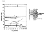
- Example 1 The part manufactured in Example 1 was subjected to ThermoCalc simulation, and the result is illustrated in FIG. 1 . Referring to FIG. 1 , it can be confirmed that MC carbide was formed in the part.
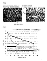
- Example 2 The part manufactured in Example 1 was cut, and a specimen was mounted such that the cut surface was 2 cm ⁇ 2 cm. Thereafter, after polishing and nital corrosion were performed, the cross section (the cut surface) was confirmed by a metal microscope, and the result is illustrated in FIG. 2 . Referring to FIG. 2 , it can be confirmed that MC carbide was formed in structure of the part.
- the cast steel composed of the composition in Example 1 and Comparative Example 4 and in the form of a tooth was subjected to primary tempering at 910°C for 2 hours, and then quenched in cooling water at 50°C. Thereafter, each of the tooth was manufactured by subjecting the cast steel to secondary tempering at 220°C for 3 hours.
- Example 5 After the tooth manufactured in Example 5 and Comparative Example 6 were coupled to a bucket of an excavator, a change in length of the tooth over time was measured by using the excavator at a road construction site, and the result is illustrated in FIG. 3 .
Landscapes
- Chemical & Material Sciences (AREA)
- Engineering & Computer Science (AREA)
- Materials Engineering (AREA)
- Organic Chemistry (AREA)
- Metallurgy (AREA)
- Mechanical Engineering (AREA)
- Crystallography & Structural Chemistry (AREA)
- Physics & Mathematics (AREA)
- Thermal Sciences (AREA)
- Mining & Mineral Resources (AREA)
- Civil Engineering (AREA)
- General Engineering & Computer Science (AREA)
- Structural Engineering (AREA)
- Component Parts Of Construction Machinery (AREA)
- Heat Treatment Of Articles (AREA)
- Refinement Of Pig-Iron, Manufacture Of Cast Iron, And Steel Manufacture Other Than In Revolving Furnaces (AREA)
Abstract
Description
- The present disclosure relates to a cast steel used to manufactureof construction equipment bucket parts.
- In general, an excavator, which is a kind of construction equipment, is an equipment that moves earth (dirt) for excavating earth and sand or rock, and has a structure in which a front part of a car body thereof includes an arm and a bucket for excavating earth and sand or rock is mounted at an end part of the arm.
- The bucket is manufactured of a steel sheet having a high hardness value in order to enhance abrasion resistance. However, since a bucket is manufactured with welding technology, there is a limitation in using a steel sheet having a high hardness value. This reason is because carbon or alloy components need to be put in to enhance the hardness, but weldability deteriorates when the content of the components is high. Accordingly, cast steel parts having a high hardness value, such as a tooth, a shroud or a cutter, are mounted and used in order to reduce damage to the bucket using a coupling method instead of welding. However, these parts also have a limitation in life span due to abrasion.
- Meanwhile, in order to enhance weldability and abrasion resistance of a tooth coupled to a bucket, a technology in which tungsten carbide having a high hardness is arc welded has been proposed (see
KR20-1999-011857 - Therefore, there is a need for developing cast steel parts showing high strength and having excellent abrasion resistance and durability in order to enhance the life span of the bucket.
- The present disclosure has been made in an effort to provide a cast steel for construction equipment bucket parts, which shows high strength and has excellent abrasion resistance and durability.
- The present disclosure has also been made in an effort to provide parts for a construction equipment bucket, which is manufactured of the cast steel for construction equipment bucket parts.
- An exemplary embodiment of the present disclosure provides a cast steel for construction equipment bucket parts, including 0.27 to 0.34 wt% of carbon (C), 1.2 to 1.8 wt% of chromium (Cr), 0.8 to 1.7 wt% of silicon (Si), 1.0 to 1.4 wt% of manganese (Mn), 0.2 to 0.4 wt% of molybdenum (Mo), 0.2 to 0.4 wt% of nickel (Ni), and a balance of iron and impurities, and including MC carbide and at least one carbide selected from M7C3 carbide, M3C2 carbide and M23C6 carbide in fa structure thereof, in which the MC carbide is included in an amount of 10 to 65 vol% based on a total 100 vol% of the entire carbide.
- The MC carbide may be included in an amount of 15 to 45 vol%.
- The MC carbide may be included in crystal particles of the cast steel, and at least one carbide selected from the M7C3 carbide, the M3C2 carbide and the M23C6 carbide may be included at a boundary of the crystal particles of the cast steel.
- In the cast steel for construction equipment bucket parts of the present disclosure, a total content of the chromium (Cr), silicon (Si) and manganese (Mn) may be 4.1 to 4.9 wt%.
- The cast steel for construction equipment bucket parts of the present disclosure may further include 0.01 to 0.03 wt% of vanadium (V).
- Another exemplary embodiment of the present disclosure provides a cast steel for construction equipment bucket parts, including 0.27 to 0.34 wt% of carbon (C), 1.2 to 1.8 wt% of chromium (Cr), 0.8 to 1.7 wt% of silicon (Si), 1.0 to 1.4 wt% of manganese (Mn), 0.2 to 0.4 wt% of molybdenum (Mo), 0.2 to 0.4 wt% of nickel (Ni), and a balance of iron and impurities, and including MC carbide and at least one carbide selected from M7C3 carbide, M3C2 carbide and M23C6 carbide in a structure thereof, in which when a cut surface after cutting is analyzed by an image analyzer, a ratio (b/a) of an area (b) of the MC carbide to an area (a) of the entire carbides is 0.1 to 0.65 at the cut surface.
- Yet another exemplary embodiment of the present disclosure provides a part for a construction equipment bucket obtained by the cast steel for construction equipment bucket parts to post-treatment.
- The part for a construction equipment bucket may be a tooth, a tooth adapter, a shroud or a cutter.
- According to the exemplary embodiments of the present disclosure, since the cast steel for construction equipment bucket parts of the present disclosure includes carbon, chromium, silicon, manganese, molybdenum and nickel in specific ranges and MC carbide in the structure thereof is included in an amount of 10 to 65 vol% based on the total amount of the entire carbides, the cast steel for construction equipment bucket parts of the present disclosure shows high strength and has excellent abrasion resistance and durability. Therefore, the parts for a construction equipment bucket, which are composed of the cast steel for construction equipment bucket parts of the present disclosure, have a long life span and excellent impact resistance.
- The foregoing summary is illustrative only and is not intended to be in any way limiting. In addition to the illustrative aspects, embodiments, and features described above, further aspects, embodiments, and features will become apparent by reference to the drawings and the following detailed description.
-
-
FIG. 1 illustrates a result of performing a ThermoCalc simulation of the part according to Example 1 of the present disclosure. -
FIG. 2 illustrates a cross-section of the part according to Example 1 of the present disclosure. -
FIG. 3 illustrates an evaluation of the life span of the tooth according to Example 5 and Comparative Example 6 of the present disclosure. - Hereinafter, the above-described present disclosure will be described in more detail.
- A cast steel for construction equipment bucket parts of the present disclosure (hereinafter, referred to as 'cast steel') includes carbon, chromium, silicon, manganese, molybdenum and nickel in specific ranges, and thus shows high strength and has excellent abrasion resistance and durability. The cast steel will be specifically described as follows.
- The cast steel of the present disclosure includes carbon (C) in an amount of 0.27 to 0.34 wt% based on the total weight. When the content of carbon is less than 0.27 wt%, the formation of carbide (particularly, MC carbide) in a structure thereof is reduced, so that abrasion resistance of the cast steel may deteriorate, and when the content is more than 0.34 wt%, strength (toughness) of the cast steel is reduced and tempering resistance deteriorates, so that abrasion resistance of the cast steel may deteriorate at high temperature. Therefore, carbon is included preferably within the range.
- The cast steel of the present disclosure includes chromium (Cr) in an amount of 1.2 to 1.8 wt% based on the total weight. When the content of chromium is less than 1.2 wt%, the formation of carbide (particularly, MC carbide) in a structure thereof is reduced, so that abrasion resistance of the cast steel may deteriorate, and when the content is more than 1.8 wt%, M7C3 carbide is mainly formed rather than MC carbide due to an increase in content of chromium compared to the content of carbon, so that strength of the cast steel may be reduced. Therefore, chromium is included preferably within the range.
- The cast steel of the present disclosure includes silicon (Si) in an amount of 0.8 to 1.7 wt% based on the total weight. When the content of silicon is less than 0.8 wt%, castability of the cast steel deteriorates, and when the content is more than 1.7 wt%, a compound (for example, SiO2) responsible for generation of defects during casting may be formed and strength of the cast steel may be reduced. Therefore, silicon is included preferably within the range.
- The cast steel of the present disclosure includes manganese (Mn) in an amount of 1.0 to 1.4 wt% based on the total weight. The manganese may serve as a deoxidizer, micronize perlite, and solid-solution strengthen ferrite, thereby enhancing yield strength of the cast steel. When the content of manganese is less than 1.0 wt%, viscosity of the cast steel may be reduced, and when the content is more than 1.4 wt%, crack or strain of the cast steel may be caused during quenching. Therefore, manganese is included preferably in the range.
- The cast steel of the present disclosure includes molybdenum (Mo) in an amount of 0.2 to 0.4 wt% based on the total weight. When the content of molybdenum is less than 0.2 wt%, brittleness of the cast steel may be reduced, and when the content is more than 0.4 wt%, preparation costs of the cast steel may be increased. Therefore, molybdenum is included preferably in the range.
- The cast steel of the present disclosure includes nickel (Ni) in an amount of 0.2 to 0.4 wt% based on the total weight. The nickel may micronize the structure of the cast steel and solid-solution strengthen austenite or ferrite, thereby enhancing yield strength of the cast steel. Further, when nickel is present together with chromium or molybdenum, hardening properties are enhanced, so thattempering may be easily performed during casting. The nickel is included preferably in the range in order to obtain a micronization effect of the structure and strength required.
- The cast steel of the present disclosure includes iron (Fe) and impurities (for example, phosphorus (P), sulfur (S) and the like) as a balance in addition to the components.
- The cast steel of the present disclosure includes carbide in a structure thereof, and the MC carbide (A) included in the carbide accounts for 10 to 65 vol%. That is, the cast steel of the present disclosure includes MC carbide (A) and at least one carbide (B) selected from the group consisting of M7C3 carbide, M3C2 carbide and M23C6 carbide in a structure thereof, and the MC carbide (A) is included in an amount of 10 to 65 vol% based on a total 100 vol% of the entire carbides (A+B). The M is a metalloid or transition metal component which may combine with carbon (C), and examples thereof include silicon (Si), chromium (Cr), molybdenum (Mo), vanadium (V) and the like.
- In general, a skeleton of dendrite is formed in the structure of the cast steel according to the solidification rate during the preparation of the cast steel, and in this case, the metalloid or transition metal combines with carbon (C) depending on the site, thereby forming a carbide such as M7C3 carbide, M3C2 carbide, MC carbide or M23C6 carbide. Among them, MC carbide is observed in the crystal particles of the cast steel structure, and the other M7C3 carbide, M3C2 carbide and M23C6 carbide are observed at the boundary of the crystal particles of the cast steel structure. Herein, since crack or impact is usually transmitted along the boundary of the crystal particles, strength and durability of the cast steel may be increased when MC carbide observed in the crystal particles is formed rather than M7C3 carbide, M3C2 carbide and M23C6 carbide, which are observed at the boundary of the crystal particles.
- Accordingly, the present disclosure may include carbon, chromium, silicon, manganese, molybdenum and nickel in specific ranges as described above to prepare a cast steel in which MC carbide in the structure accounts for 10 vol% or more based on the total 100 vol% of the entire carbides, thereby providing a cast steel showing high strength and having excellent durability and impact resistance.
- Therefore, when parts for a construction equipment bucket are manufactured with the cast steel of the present disclosure and applied to a bucket, strength and durability of the bucket may be increased without any post-treatment processing (a tungsten carbide treatment such as
KR20-1999-011857 - Meanwhile, the volume of MC carbide present in the cast steel of the present disclosure may be measured by observing the cross-section of the cast steel by a microscope and performing a phase analysis on carbides (that is, M7C3 carbide, M3C2 carbide or M23C6 carbide) observed at the boundary of the crystal particles and carbide (that is, MC carbide) observed in the crystal particles by an image analyzer. The specific measurement method is as follows.
- First, when the thickness (or length) of the cast steel begins from A1 and ends at A3, the cast steel is cut in a direction vertical to the ground at each point of A1, A2 and A3. Next, each of the cut surfaces is image-analyzed, and the areas occupied by carbides observed at the boundary of the crystal particles (carbides present at the boundary of the crystal particles) and carbide observed in the crystal particles (carbide present in the crystal particles) are measured at each of the cut surfaces. Thereafter, the volume (V) of MC carbide included in the cast steel having a thickness from A1 to A3 may be calculated by the following equation.
- V = {(the area which carbide observed in the crystal particles occupies at the cut surface of A1 point / the total area which carbide observed at the boundary of the crystal particles and carbide observed in the crystal particles occupy at the cut surface of A1 point) + (the area which carbide observed in the crystal particles occupies at the cut surface of A2 point / the total area which carbide observed at the boundary of the crystal particles and carbide observed in the crystal particles occupy at the cut surface of A2 point) + (the area which carbide observed in the crystal particles occupies at the cut surface of A3 point / the total area which carbide observed at the boundary of the crystal particles and carbide observed in the crystal particles occupy at the cut surface of A3 point)} × 3
- As described above, the volume of MC carbide included in the cast steel of the present disclosure is 10 to 65 vol% based on the total 100 vol% of the entire carbides, and may be represented as 0.1 to 0.65 when the volume is applied as a ratio of the area.
- Specifically, in the cast steel of the present disclosure, when a cut surface after cutting is analyzed by an image analyzer, a ratio (b/a) of an area (b) occupied by the MC carbide (carbide present in the crystal particles) to an area (a) occupied by the entire carbides (carbide present at the boundary of the crystal particles and carbide present in the crystal particles) is 0.1 to 0.65 at the cut surface.
- Meanwhile, it is preferred that the cast steel of the present disclosure includes chromium, silicon and manganese in the ranges, in which the total content thereof (Cr + Si + Mn) is 4.1 to 4.9 wt%. When the total content of chromium, silicon and manganese included in the cast steel is less than 4.1 wt%, strength of the cast steel may be decreased. Specifically, when the total content of chromium, silicon and manganese is less than 4.1 wt%, MC carbide greatly affecting strength and durability of the cast steel may not be formed or may be formed in an amount less than 10 vol%, thereby making strength and durability of the cast steel may deteriorate. Therefore, it is preferred that the total content of chromium, silicon and manganese is 4.1 wt% or more, and in consideration of each content, it is preferred that the total content thereof does not exceed 4.9 wt%.
- The cast steel of the present disclosure may include vanadium (V) in an amount of 0.01 to 0.03 wt% based on the total weight in order to enhance strength (toughness). The vanadium may form fine particle carbide to micronize the structure of the cast steel, thereby enhancing strength of the cast steel. The vanadium is included preferably in the range in order to obtain a micronization effect and strength required.
- A method of preparing the cast steel of the present disclosure is not particularly limited, but a lost wax casting process, a shell mold process, a green sand casting process and the like may be used to manufacture the cast steel.
- The present disclosure provides parts for a construction equipment bucket obtained by subjecting the cast steel to post-treatment. Specifically, the parts for a construction equipment bucket of the present disclosure may be manufactured by subjecting the cast steel to post-treatment such as tempering and/or quenching. The parts for a construction equipment bucket of the present disclosure are composed of the cast steel described above, and thus have a long life span and excellent durability and impact resistance.
- The parts for a construction equipment bucket of the present disclosure are not particularly limited, but are preferably a tooth, a tooth adapter, a shroud or a cutter.
- Specifically, the parts for a construction equipment bucket of the present disclosure may be a tooth showing a 47 to 52 HRC in core hardness and a 50 HRC in surface hardness, which is obtained by subjecting the cast steel to tempering in a range from 880°C to 930°C, quenching in cooling water in a range from 40°C to 80°C, and then again tempering in a range from 190°C to 240°C.
- The parts for a construction equipment bucket of the present disclosure may be a tooth adapter showing a 28 to 34 HRC in core hardness and a 30 to 40 HRC in surface hardness, which is obtained by subjecting the cast steel to tempering in a range from 880°C to 930°C, quenching in cooling water in a range from 40°C to 80°C, and then again tempering in a range from 480°C to 530°C.
- The parts for a construction equipment bucket of the present disclosure may be a shroud or cuttershowing a 47 to 50 HRC in core hardness and a 48 to 53 HRC in surface hardness, which is obtained by subjecting the cast steel to tempering in a range from 880°C to 930°C, quenching in cooling water in a range from 40°C to 80°C, and then again tempering in a range from 190°C to 240°C.
- Hereinafter, the present disclosure will be specifically described through Examples, but the following Examples only illustrate one form of the present disclosure, and the scope of the present disclosure is not limited by the following Examples.
- [Examples 1 to 4 and Comparative Examples 1 to 5]
- Table 1 was prepared through a green sand casting process, subjected to primary tempering at 910°C for 2 hours, and then quenched in cooling water at 50°C. Thereafter, each of the parts was manufactured by subjecting the cast steel to secondary tempering at 220°C for 3 hours.
[Table 1] Type Chemical Analysis, wt% C Si Mn P S Cr Mo Ni Fe Si+Mn+Cr Example 1 0.30 1.52 1.01 0.015 0.009 1.61 0.28 0.25 Balance 4.14 Example 2 0.34 1.3 1.3 0.023 0.012 1.52 0.25 0.21 Balance 4.12 Example 3 0.29 1.40 1.21 0.023 0.012 1.51 0.27 0.22 Balance 4.12 Example 4 0.33 1.52 1.39 0.015 0.008 1.78 0.27 0.29 Balance 4.69 Comparative Example 1 0.28 1.69 1.31 0.018 0.012 1.11 0.29 0.23 Balance 4.11 Comparative Example 2 0.25 1.30 1.17 0.022 0.007 1.63 0.23 0.01 Balance 4.10 Comparative Example 3 0.32 1.2 0.96 0.025 0.003 0.9 0.21 0.01 Balance 3.06 Comparative Example 4 0.29 0.81 1.00 0.020 0.010 1.53 0.24 0.11 Balance 3.34 Comparative Example 5 0.33 1.78 1.35 0.018 0.010 1.75 0.23 0.25 Balance 4.88 - The part manufactured in Example 1 was subjected to ThermoCalc simulation, and the result is illustrated in
FIG. 1 . Referring toFIG. 1 , it can be confirmed that MC carbide was formed in the part. - The part manufactured in Example 1 was cut, and a specimen was mounted such that the cut surface was 2 cm × 2 cm. Thereafter, after polishing and nital corrosion were performed, the cross section (the cut surface) was confirmed by a metal microscope, and the result is illustrated in
FIG. 2 . Referring toFIG. 2 , it can be confirmed that MC carbide was formed in structure of the part. - Physical properties of the parts manufactured in Examples 1 to 4 and Comparative Examples 1 to 5 were evaluated by the following method, and the results are shown in the following Table 2.
- 1. Surface hardness: measured by a Rockwell hardness tester (150 kg).
- 2. Abrasion amount of earth and sand: evaluated in accordance with the ASTM G65-85 (Standard Practice for Conducting Dry Sand/Runner Wheel Abrasion Tests).
- 3. Impact energy: measured using a Charpy impact tester. In this case, V notch was performed on an impact specimen.
- 4. Ratio (b/a) of an area (b) of MC carbide to an area (a) of carbide: after the part was cut vertically, the cut surface was observed by a metal microscope, a phase analysis was performed by an image analyzer manufactured by Leica, Inc., and then the ratio was calculated by the following equation.

- Referring to Table 2, it can be confirmed that the parts according to the present disclosure (Examples 1 to 4) have high strength and are excellent in durability and abrasion resistance.
- Meanwhile, it can be confirmed that abrasion resistance deteriorates due to insufficient content of Cr in Comparative Example 1, and durability and strength deteriorate due to insufficient content of C in Comparative Example 2. Further, it can be confirmed in Comparative Example 3 that durability and strength deteriorate due to insufficient content of Si+Mn+Cr and insufficient content of Mn, and in Comparative Example 4 that durability and strength deteriorate due to insufficient content of Si+Mn+Cr and insufficient content of Ni. In addition, it can be confirmed in Comparative Example 5 that as the content of Si exceeds, impact characteristics significantly deteriorate.
- The cast steel composed of the composition in Example 1 and Comparative Example 4 and in the form of a tooth was subjected to primary tempering at 910°C for 2 hours, and then quenched in cooling water at 50°C. Thereafter, each of the tooth was manufactured by subjecting the cast steel to secondary tempering at 220°C for 3 hours.
- After the tooth manufactured in Example 5 and Comparative Example 6 were coupled to a bucket of an excavator, a change in length of the tooth over time was measured by using the excavator at a road construction site, and the result is illustrated in
FIG. 3 . - Referring to
FIG. 3 , it can be confirmed that the life span of the tooth in Example 5 was enhanced by two times or more than that of the tooth in Comparative Example 6.
| Surface hardness (HRC) | Abrasion amount of earth and sand (mm3) | Impact energy (toughness) (Joule, -40°C) | Ratio (b/a) | |
| Example 1 | 51.0 | 162.0 | 26.5 | 0.21 |
| Example 2 | 52.1 | 161.4 | 24.0 | 0.19 |
| Example 3 | 50.9 | 171.9 | 24.9 | 0.1 |
| Example 4 | 51.5 | 158.3 | 15.9 | 0.65 |
| Comparative Example 1 | 48.7 | 198.6 | 11.5 | 0.08 |
| Comparative Example 2 | 47.0 | 212.2 | 10.5 | 0.03 |
| Comparative Example 3 | 44.4 | 312.2 | 7.5 | 0 |
| Comparative Example 4 | 45.2 | 297.2 | 11.0 | 0.05 |
| Comparative Example 5 | 51.7 | 162.1 | 2.8 | 0.77 |
Claims (9)
- A cast steel for use with a construction equipment bucket part, comprising 0.27 to 0.34 wt% of carbon (C), 1.2 to 1.8 wt% of chromium (Cr), 0.8 to 1.7 wt% of silicon (Si), 1.0 to 1.4 wt% of manganese (Mn), 0.2 to 0.4 wt% of molybdenum (Mo), 0.2 to 0.4 wt% of nickel (Ni), and a balance of iron and impurities, and
comprising MC carbide and at least one carbide selected from M7C3 carbide, M3C2 carbide and M23C6 carbide in a structure thereof,
wherein the MC carbide is comprised in an amount of 10 to 65 vol% based on a total 100 vol% of the entire carbides. - The cast steel for use with a construction equipment bucket part of claim 1, wherein the MC carbide is comprised in an amount of 15 to 45 vol%.
- The cast steel for use with a construction equipment bucket part of claim 1, wherein the MC carbide is comprised in crystal particles of the cast steel, and at least one carbide selected from the M7C3 carbide, the M3C2 carbide and the M23C6 carbide is comprised at a boundary of the crystal particles of the cast steel.
- The cast steel for use with a construction equipment bucket part of claim 1, wherein a total content of the chromium (Cr), silicon (Si) and manganese (Mn) is 4.1 to 4.9 wt%.
- The cast steel for use with a construction equipment bucket part of claim 1, further comprising 0.01 to 0.03 wt% of vanadium (V).
- A cast steel for use with a construction equipment bucket part, comprising 0.27 to 0.34 wt% of carbon (C), 1.2 to 1.8 wt% of chromium (Cr), 0.8 to 1.7 wt% of silicon (Si), 1.0 to 1.4 wt% of manganese (Mn), 0.2 to 0.4 wt% of molybdenum (Mo), 0.2 to 0.4 wt% of nickel (Ni), and a balance of iron and impurities, and
comprising MC carbide and at least one carbide selected from M7C3 carbide, M3C2 carbide and M23C6 carbide in a structure thereof,
wherein when a cut surface after cutting is analyzed by an image analyzer, a ratio (b/a) of an area (b) of the MC carbide to an area (a) of the entire carbide is 0.1 to 0.65 at a cut surface. - The cast steel for use with a construction equipment bucket part of claim 6, wherein the MC carbide is comprised in crystal particles of the cast steel, and at least one carbide selected from the M7C3 carbide, the M3C2 carbide and the M23C6 carbide is comprised at a boundary of the crystal particles of the cast steel.
- A part for use with a construction equipment bucket obtained by the cast steel of any one of claims 1 to 7 to post-treatment.
- The part for use with a construction equipment bucket of claim 8, wherein the part is selected from a tooth, a tooth adapter, a shroud or a cutter.
Applications Claiming Priority (1)
| Application Number | Priority Date | Filing Date | Title |
|---|---|---|---|
| KR1020130163747A KR102205618B1 (en) | 2013-12-26 | 2013-12-26 | Cast steel for construction equipment bucket parts and parts for construction equipment bucket comprising the same |
Publications (3)
| Publication Number | Publication Date |
|---|---|
| EP2889394A2 true EP2889394A2 (en) | 2015-07-01 |
| EP2889394A3 EP2889394A3 (en) | 2015-09-02 |
| EP2889394B1 EP2889394B1 (en) | 2017-10-11 |
Family
ID=51355477
Family Applications (1)
| Application Number | Title | Priority Date | Filing Date |
|---|---|---|---|
| EP14181315.4A Active EP2889394B1 (en) | 2013-12-26 | 2014-08-18 | Cast steel for construction equipment bucket parts and parts for construction equipment bucket comprising the same |
Country Status (4)
| Country | Link |
|---|---|
| US (1) | US9896823B2 (en) |
| EP (1) | EP2889394B1 (en) |
| KR (1) | KR102205618B1 (en) |
| CN (2) | CN107881436A (en) |
Citations (1)
| Publication number | Priority date | Publication date | Assignee | Title |
|---|---|---|---|---|
| KR19990011857U (en) | 1998-12-17 | 1999-03-25 | 이금형 | Tubscap installed in front lower part of shovel fork |
Family Cites Families (14)
| Publication number | Priority date | Publication date | Assignee | Title |
|---|---|---|---|---|
| US3600160A (en) * | 1968-05-14 | 1971-08-17 | Wallace Murray Corp | Heat and temper resistant alloy steel |
| FR2733516B1 (en) | 1995-04-27 | 1997-05-30 | Creusot Loire | STEEL AND PROCESS FOR THE MANUFACTURE OF PARTS WITH HIGH ABRASION RESISTANCE |
| KR19990011857A (en) | 1997-07-25 | 1999-02-18 | 양재신 | Cold start control method of car |
| JP2001152252A (en) | 1999-11-22 | 2001-06-05 | Nsk Ltd | Rolling bearing |
| JP2005068453A (en) * | 2003-08-28 | 2005-03-17 | Nissan Motor Co Ltd | High surface pressure resistant parts and manufacturing method thereof |
| CN1242087C (en) * | 2004-01-18 | 2006-02-15 | 江苏省机电研究所有限公司 | High hardness high ductility wear-resistant steel |
| US7520942B2 (en) * | 2004-09-22 | 2009-04-21 | Ut-Battelle, Llc | Nano-scale nitride-particle-strengthened high-temperature wrought ferritic and martensitic steels |
| CN1313634C (en) * | 2004-12-16 | 2007-05-02 | 邹乐平 | Complex alloy cast-steel excavator bucket teeth and its producing process |
| CN101899551B (en) * | 2009-05-26 | 2011-11-16 | 宁波市鄞州商业精密铸造有限公司 | Heat treatment technology of wear-resistant alloy cast steel |
| CN102010964A (en) * | 2010-12-21 | 2011-04-13 | 柳州市友军机械配件铸造有限公司 | Heating treatment technology for low-alloy bucket lip mesh tape |
| CN102277535B (en) * | 2011-08-12 | 2013-06-05 | 宁波万冠精密铸造厂 | Ridger tooth alloy material and preparation method thereof |
| CN102367558B (en) * | 2011-10-24 | 2016-05-04 | 山东双轮股份有限公司 | A kind of pump boric low alloy wear resistant steel |
| CN102758067A (en) * | 2012-06-29 | 2012-10-31 | 暨南大学 | Thermal treatment method for wear-resistant low alloy steel |
| CN103436808B (en) * | 2013-08-28 | 2015-07-29 | 武汉武船金属制造有限责任公司 | A kind of low-carbon-equivalent high-strong toughness cast steel and preparation method thereof |
-
2013
- 2013-12-26 KR KR1020130163747A patent/KR102205618B1/en active Active
-
2014
- 2014-08-18 EP EP14181315.4A patent/EP2889394B1/en active Active
- 2014-08-19 CN CN201711267241.2A patent/CN107881436A/en active Pending
- 2014-08-19 CN CN201410408755.5A patent/CN104745951A/en active Pending
- 2014-09-11 US US14/483,727 patent/US9896823B2/en active Active
Patent Citations (1)
| Publication number | Priority date | Publication date | Assignee | Title |
|---|---|---|---|---|
| KR19990011857U (en) | 1998-12-17 | 1999-03-25 | 이금형 | Tubscap installed in front lower part of shovel fork |
Also Published As
| Publication number | Publication date |
|---|---|
| CN104745951A (en) | 2015-07-01 |
| US20150184365A1 (en) | 2015-07-02 |
| EP2889394B1 (en) | 2017-10-11 |
| EP2889394A3 (en) | 2015-09-02 |
| KR20150075614A (en) | 2015-07-06 |
| CN107881436A (en) | 2018-04-06 |
| KR102205618B1 (en) | 2021-01-21 |
| US9896823B2 (en) | 2018-02-20 |
Similar Documents
| Publication | Publication Date | Title |
|---|---|---|
| US8216400B2 (en) | High-strength steel plate and producing method therefor | |
| JP5380892B2 (en) | Wear-resistant steel plate with excellent workability and method for producing the same | |
| EP2589676B1 (en) | Abrasion-resistant steel plate or sheet with excellent weld toughness and delayed fracture resistance | |
| JP5655356B2 (en) | Wear-resistant steel plate with excellent low-temperature temper embrittlement cracking | |
| JP4542624B2 (en) | High strength thick steel plate and manufacturing method thereof | |
| CN102392186B (en) | Manufacturing method of HB500 grade low-manganese wear-resistant steel plate | |
| JP5186809B2 (en) | Wear-resistant steel plate with excellent workability and method for producing the same | |
| KR20130025947A (en) | Wear-resistant steel sheet having excellent welded part toughness and lagging destruction resistance properties | |
| JP6027302B2 (en) | High strength tempered spring steel | |
| KR102627470B1 (en) | Construction equipment bucket parts and methods of manufacturing the same | |
| US20250034687A1 (en) | High-strength and high-hardness reinforced wear-resistant steel and manufacturing method therefor | |
| JP6180984B2 (en) | Steel plates for chainsaw parts and chainsaw parts | |
| JP7274287B2 (en) | Impact wear resistant part and manufacturing method thereof | |
| KR20150066373A (en) | Welded joint having excellent impact resistance and abrasion resistance properties | |
| JP5458624B2 (en) | Wear-resistant steel plate with excellent workability and method for producing the same | |
| JP7370992B2 (en) | High tensile strength steel and high toughness steel | |
| JP5217191B2 (en) | Wear-resistant steel plate with excellent workability and method for producing the same | |
| US9896823B2 (en) | Cast steel for construction equipment bucket parts and parts for construction equipment bucket comprising the same | |
| JP3970801B2 (en) | High strength high toughness steel plate | |
| JP2008111146A (en) | Excavation tool blade steel or rock drilling tool blade steel, and method for producing the same | |
| JP3536001B2 (en) | Cast steel for welded structures | |
| Rizov | Some results from the investigation of effects of heat treatment on properties of ni-hard cast irons | |
| JP2020015927A (en) | Alloy steel for machine structure with excellent impact resistance | |
| JP2021127513A (en) | Alloy steel for mechanical structure excellent in balance of hardness and toughness |
Legal Events
| Date | Code | Title | Description |
|---|---|---|---|
| PUAI | Public reference made under article 153(3) epc to a published international application that has entered the european phase |
Free format text: ORIGINAL CODE: 0009012 |
|
| 17P | Request for examination filed |
Effective date: 20140818 |
|
| AK | Designated contracting states |
Kind code of ref document: A2 Designated state(s): AL AT BE BG CH CY CZ DE DK EE ES FI FR GB GR HR HU IE IS IT LI LT LU LV MC MK MT NL NO PL PT RO RS SE SI SK SM TR |
|
| AX | Request for extension of the european patent |
Extension state: BA ME |
|
| PUAL | Search report despatched |
Free format text: ORIGINAL CODE: 0009013 |
|
| AK | Designated contracting states |
Kind code of ref document: A3 Designated state(s): AL AT BE BG CH CY CZ DE DK EE ES FI FR GB GR HR HU IE IS IT LI LT LU LV MC MK MT NL NO PL PT RO RS SE SI SK SM TR |
|
| AX | Request for extension of the european patent |
Extension state: BA ME |
|
| RIC1 | Information provided on ipc code assigned before grant |
Ipc: C21D 6/00 20060101ALI20150724BHEP Ipc: C22C 38/04 20060101ALI20150724BHEP Ipc: C22C 38/34 20060101ALI20150724BHEP Ipc: C22C 38/02 20060101AFI20150724BHEP Ipc: C22C 38/44 20060101ALI20150724BHEP Ipc: C21D 6/02 20060101ALI20150724BHEP |
|
| R17P | Request for examination filed (corrected) |
Effective date: 20160301 |
|
| RBV | Designated contracting states (corrected) |
Designated state(s): AL AT BE BG CH CY CZ DE DK EE ES FI FR GB GR HR HU IE IS IT LI LT LU LV MC MK MT NL NO PL PT RO RS SE SI SK SM TR |
|
| REG | Reference to a national code |
Ref country code: DE Ref legal event code: R079 Ref document number: 602014015614 Country of ref document: DE Free format text: PREVIOUS MAIN CLASS: C22C0038020000 Ipc: C22C0038000000 |
|
| GRAP | Despatch of communication of intention to grant a patent |
Free format text: ORIGINAL CODE: EPIDOSNIGR1 |
|
| STAA | Information on the status of an ep patent application or granted ep patent |
Free format text: STATUS: GRANT OF PATENT IS INTENDED |
|
| RIC1 | Information provided on ipc code assigned before grant |
Ipc: C21D 9/00 20060101ALI20170328BHEP Ipc: C22C 38/04 20060101ALI20170328BHEP Ipc: C22C 38/34 20060101ALI20170328BHEP Ipc: C22C 38/02 20060101ALI20170328BHEP Ipc: C22C 38/00 20060101AFI20170328BHEP Ipc: C21D 6/02 20060101ALI20170328BHEP Ipc: C22C 38/44 20060101ALI20170328BHEP Ipc: C21D 6/00 20060101ALI20170328BHEP |
|
| INTG | Intention to grant announced |
Effective date: 20170411 |
|
| RIN1 | Information on inventor provided before grant (corrected) |
Inventor name: SHIM, YOUNG JI Inventor name: SHIM, DONG SEOB Inventor name: LEE, CHOUNG RAE Inventor name: AN, SANG MIN Inventor name: SONG, SEOK WON |
|
| GRAS | Grant fee paid |
Free format text: ORIGINAL CODE: EPIDOSNIGR3 |
|
| GRAA | (expected) grant |
Free format text: ORIGINAL CODE: 0009210 |
|
| STAA | Information on the status of an ep patent application or granted ep patent |
Free format text: STATUS: THE PATENT HAS BEEN GRANTED |
|
| AK | Designated contracting states |
Kind code of ref document: B1 Designated state(s): AL AT BE BG CH CY CZ DE DK EE ES FI FR GB GR HR HU IE IS IT LI LT LU LV MC MK MT NL NO PL PT RO RS SE SI SK SM TR |
|
| REG | Reference to a national code |
Ref country code: GB Ref legal event code: FG4D |
|
| REG | Reference to a national code |
Ref country code: CH Ref legal event code: EP |
|
| REG | Reference to a national code |
Ref country code: IE Ref legal event code: FG4D |
|
| REG | Reference to a national code |
Ref country code: AT Ref legal event code: REF Ref document number: 936089 Country of ref document: AT Kind code of ref document: T Effective date: 20171115 |
|
| REG | Reference to a national code |
Ref country code: DE Ref legal event code: R096 Ref document number: 602014015614 Country of ref document: DE |
|
| REG | Reference to a national code |
Ref country code: NL Ref legal event code: MP Effective date: 20171011 |
|
| REG | Reference to a national code |
Ref country code: LT Ref legal event code: MG4D |
|
| REG | Reference to a national code |
Ref country code: AT Ref legal event code: MK05 Ref document number: 936089 Country of ref document: AT Kind code of ref document: T Effective date: 20171011 |
|
| PG25 | Lapsed in a contracting state [announced via postgrant information from national office to epo] |
Ref country code: NL Free format text: LAPSE BECAUSE OF FAILURE TO SUBMIT A TRANSLATION OF THE DESCRIPTION OR TO PAY THE FEE WITHIN THE PRESCRIBED TIME-LIMIT Effective date: 20171011 |
|
| PG25 | Lapsed in a contracting state [announced via postgrant information from national office to epo] |
Ref country code: LT Free format text: LAPSE BECAUSE OF FAILURE TO SUBMIT A TRANSLATION OF THE DESCRIPTION OR TO PAY THE FEE WITHIN THE PRESCRIBED TIME-LIMIT Effective date: 20171011 Ref country code: FI Free format text: LAPSE BECAUSE OF FAILURE TO SUBMIT A TRANSLATION OF THE DESCRIPTION OR TO PAY THE FEE WITHIN THE PRESCRIBED TIME-LIMIT Effective date: 20171011 Ref country code: ES Free format text: LAPSE BECAUSE OF FAILURE TO SUBMIT A TRANSLATION OF THE DESCRIPTION OR TO PAY THE FEE WITHIN THE PRESCRIBED TIME-LIMIT Effective date: 20171011 Ref country code: SE Free format text: LAPSE BECAUSE OF FAILURE TO SUBMIT A TRANSLATION OF THE DESCRIPTION OR TO PAY THE FEE WITHIN THE PRESCRIBED TIME-LIMIT Effective date: 20171011 Ref country code: NO Free format text: LAPSE BECAUSE OF FAILURE TO SUBMIT A TRANSLATION OF THE DESCRIPTION OR TO PAY THE FEE WITHIN THE PRESCRIBED TIME-LIMIT Effective date: 20180111 |
|
| PG25 | Lapsed in a contracting state [announced via postgrant information from national office to epo] |
Ref country code: IS Free format text: LAPSE BECAUSE OF FAILURE TO SUBMIT A TRANSLATION OF THE DESCRIPTION OR TO PAY THE FEE WITHIN THE PRESCRIBED TIME-LIMIT Effective date: 20180211 Ref country code: GR Free format text: LAPSE BECAUSE OF FAILURE TO SUBMIT A TRANSLATION OF THE DESCRIPTION OR TO PAY THE FEE WITHIN THE PRESCRIBED TIME-LIMIT Effective date: 20180112 Ref country code: LV Free format text: LAPSE BECAUSE OF FAILURE TO SUBMIT A TRANSLATION OF THE DESCRIPTION OR TO PAY THE FEE WITHIN THE PRESCRIBED TIME-LIMIT Effective date: 20171011 Ref country code: RS Free format text: LAPSE BECAUSE OF FAILURE TO SUBMIT A TRANSLATION OF THE DESCRIPTION OR TO PAY THE FEE WITHIN THE PRESCRIBED TIME-LIMIT Effective date: 20171011 Ref country code: HR Free format text: LAPSE BECAUSE OF FAILURE TO SUBMIT A TRANSLATION OF THE DESCRIPTION OR TO PAY THE FEE WITHIN THE PRESCRIBED TIME-LIMIT Effective date: 20171011 Ref country code: AT Free format text: LAPSE BECAUSE OF FAILURE TO SUBMIT A TRANSLATION OF THE DESCRIPTION OR TO PAY THE FEE WITHIN THE PRESCRIBED TIME-LIMIT Effective date: 20171011 Ref country code: BG Free format text: LAPSE BECAUSE OF FAILURE TO SUBMIT A TRANSLATION OF THE DESCRIPTION OR TO PAY THE FEE WITHIN THE PRESCRIBED TIME-LIMIT Effective date: 20180111 |
|
| REG | Reference to a national code |
Ref country code: FR Ref legal event code: PLFP Year of fee payment: 5 Ref country code: DE Ref legal event code: R097 Ref document number: 602014015614 Country of ref document: DE |
|
| PG25 | Lapsed in a contracting state [announced via postgrant information from national office to epo] |
Ref country code: SK Free format text: LAPSE BECAUSE OF FAILURE TO SUBMIT A TRANSLATION OF THE DESCRIPTION OR TO PAY THE FEE WITHIN THE PRESCRIBED TIME-LIMIT Effective date: 20171011 Ref country code: EE Free format text: LAPSE BECAUSE OF FAILURE TO SUBMIT A TRANSLATION OF THE DESCRIPTION OR TO PAY THE FEE WITHIN THE PRESCRIBED TIME-LIMIT Effective date: 20171011 Ref country code: DK Free format text: LAPSE BECAUSE OF FAILURE TO SUBMIT A TRANSLATION OF THE DESCRIPTION OR TO PAY THE FEE WITHIN THE PRESCRIBED TIME-LIMIT Effective date: 20171011 Ref country code: CZ Free format text: LAPSE BECAUSE OF FAILURE TO SUBMIT A TRANSLATION OF THE DESCRIPTION OR TO PAY THE FEE WITHIN THE PRESCRIBED TIME-LIMIT Effective date: 20171011 |
|
| PLBE | No opposition filed within time limit |
Free format text: ORIGINAL CODE: 0009261 |
|
| STAA | Information on the status of an ep patent application or granted ep patent |
Free format text: STATUS: NO OPPOSITION FILED WITHIN TIME LIMIT |
|
| PG25 | Lapsed in a contracting state [announced via postgrant information from national office to epo] |
Ref country code: SM Free format text: LAPSE BECAUSE OF FAILURE TO SUBMIT A TRANSLATION OF THE DESCRIPTION OR TO PAY THE FEE WITHIN THE PRESCRIBED TIME-LIMIT Effective date: 20171011 Ref country code: PL Free format text: LAPSE BECAUSE OF FAILURE TO SUBMIT A TRANSLATION OF THE DESCRIPTION OR TO PAY THE FEE WITHIN THE PRESCRIBED TIME-LIMIT Effective date: 20171011 Ref country code: IT Free format text: LAPSE BECAUSE OF FAILURE TO SUBMIT A TRANSLATION OF THE DESCRIPTION OR TO PAY THE FEE WITHIN THE PRESCRIBED TIME-LIMIT Effective date: 20171011 Ref country code: RO Free format text: LAPSE BECAUSE OF FAILURE TO SUBMIT A TRANSLATION OF THE DESCRIPTION OR TO PAY THE FEE WITHIN THE PRESCRIBED TIME-LIMIT Effective date: 20171011 |
|
| 26N | No opposition filed |
Effective date: 20180712 |
|
| PG25 | Lapsed in a contracting state [announced via postgrant information from national office to epo] |
Ref country code: SI Free format text: LAPSE BECAUSE OF FAILURE TO SUBMIT A TRANSLATION OF THE DESCRIPTION OR TO PAY THE FEE WITHIN THE PRESCRIBED TIME-LIMIT Effective date: 20171011 |
|
| PG25 | Lapsed in a contracting state [announced via postgrant information from national office to epo] |
Ref country code: MC Free format text: LAPSE BECAUSE OF FAILURE TO SUBMIT A TRANSLATION OF THE DESCRIPTION OR TO PAY THE FEE WITHIN THE PRESCRIBED TIME-LIMIT Effective date: 20171011 |
|
| REG | Reference to a national code |
Ref country code: CH Ref legal event code: PL |
|
| PG25 | Lapsed in a contracting state [announced via postgrant information from national office to epo] |
Ref country code: LI Free format text: LAPSE BECAUSE OF NON-PAYMENT OF DUE FEES Effective date: 20180831 Ref country code: LU Free format text: LAPSE BECAUSE OF NON-PAYMENT OF DUE FEES Effective date: 20180818 Ref country code: CH Free format text: LAPSE BECAUSE OF NON-PAYMENT OF DUE FEES Effective date: 20180831 |
|
| REG | Reference to a national code |
Ref country code: BE Ref legal event code: MM Effective date: 20180831 |
|
| REG | Reference to a national code |
Ref country code: IE Ref legal event code: MM4A |
|
| PG25 | Lapsed in a contracting state [announced via postgrant information from national office to epo] |
Ref country code: IE Free format text: LAPSE BECAUSE OF NON-PAYMENT OF DUE FEES Effective date: 20180818 |
|
| PG25 | Lapsed in a contracting state [announced via postgrant information from national office to epo] |
Ref country code: BE Free format text: LAPSE BECAUSE OF NON-PAYMENT OF DUE FEES Effective date: 20180831 |
|
| PG25 | Lapsed in a contracting state [announced via postgrant information from national office to epo] |
Ref country code: MT Free format text: LAPSE BECAUSE OF NON-PAYMENT OF DUE FEES Effective date: 20180818 |
|
| PG25 | Lapsed in a contracting state [announced via postgrant information from national office to epo] |
Ref country code: TR Free format text: LAPSE BECAUSE OF FAILURE TO SUBMIT A TRANSLATION OF THE DESCRIPTION OR TO PAY THE FEE WITHIN THE PRESCRIBED TIME-LIMIT Effective date: 20171011 |
|
| PG25 | Lapsed in a contracting state [announced via postgrant information from national office to epo] |
Ref country code: PT Free format text: LAPSE BECAUSE OF FAILURE TO SUBMIT A TRANSLATION OF THE DESCRIPTION OR TO PAY THE FEE WITHIN THE PRESCRIBED TIME-LIMIT Effective date: 20171011 |
|
| PG25 | Lapsed in a contracting state [announced via postgrant information from national office to epo] |
Ref country code: MK Free format text: LAPSE BECAUSE OF NON-PAYMENT OF DUE FEES Effective date: 20171011 Ref country code: HU Free format text: LAPSE BECAUSE OF FAILURE TO SUBMIT A TRANSLATION OF THE DESCRIPTION OR TO PAY THE FEE WITHIN THE PRESCRIBED TIME-LIMIT; INVALID AB INITIO Effective date: 20140818 Ref country code: CY Free format text: LAPSE BECAUSE OF FAILURE TO SUBMIT A TRANSLATION OF THE DESCRIPTION OR TO PAY THE FEE WITHIN THE PRESCRIBED TIME-LIMIT Effective date: 20171011 |
|
| PG25 | Lapsed in a contracting state [announced via postgrant information from national office to epo] |
Ref country code: AL Free format text: LAPSE BECAUSE OF FAILURE TO SUBMIT A TRANSLATION OF THE DESCRIPTION OR TO PAY THE FEE WITHIN THE PRESCRIBED TIME-LIMIT Effective date: 20171011 |
|
| REG | Reference to a national code |
Ref country code: DE Ref legal event code: R081 Ref document number: 602014015614 Country of ref document: DE Owner name: HYUNDAI DOOSAN INFRACORE CO., LTD., KR Free format text: FORMER OWNER: DOOSAN INFRACORE CO., LTD., DONG-GU, INCHEON, KR Ref country code: DE Ref legal event code: R081 Ref document number: 602014015614 Country of ref document: DE Owner name: HD HYUNDAI INFRACORE CO., LTD., KR Free format text: FORMER OWNER: DOOSAN INFRACORE CO., LTD., DONG-GU, INCHEON, KR |
|
| REG | Reference to a national code |
Ref country code: DE Ref legal event code: R081 Ref document number: 602014015614 Country of ref document: DE Owner name: HD HYUNDAI INFRACORE CO., LTD., KR Free format text: FORMER OWNER: HYUNDAI DOOSAN INFRACORE CO., LTD., INCHEON, KR |
|
| PGFP | Annual fee paid to national office [announced via postgrant information from national office to epo] |
Ref country code: DE Payment date: 20250730 Year of fee payment: 12 |
|
| PGFP | Annual fee paid to national office [announced via postgrant information from national office to epo] |
Ref country code: GB Payment date: 20250731 Year of fee payment: 12 |
|
| PGFP | Annual fee paid to national office [announced via postgrant information from national office to epo] |
Ref country code: FR Payment date: 20250808 Year of fee payment: 12 |