EP2889190A1 - Side airbag, airbag apparatus, method of making side airbag - Google Patents
Side airbag, airbag apparatus, method of making side airbag Download PDFInfo
- Publication number
- EP2889190A1 EP2889190A1 EP14199672.8A EP14199672A EP2889190A1 EP 2889190 A1 EP2889190 A1 EP 2889190A1 EP 14199672 A EP14199672 A EP 14199672A EP 2889190 A1 EP2889190 A1 EP 2889190A1
- Authority
- EP
- European Patent Office
- Prior art keywords
- edge part
- face
- panel
- side airbag
- joining
- Prior art date
- Legal status (The legal status is an assumption and is not a legal conclusion. Google has not performed a legal analysis and makes no representation as to the accuracy of the status listed.)
- Granted
Links
Images




Classifications
-
- B—PERFORMING OPERATIONS; TRANSPORTING
- B60—VEHICLES IN GENERAL
- B60R—VEHICLES, VEHICLE FITTINGS, OR VEHICLE PARTS, NOT OTHERWISE PROVIDED FOR
- B60R21/00—Arrangements or fittings on vehicles for protecting or preventing injuries to occupants or pedestrians in case of accidents or other traffic risks
- B60R21/02—Occupant safety arrangements or fittings, e.g. crash pads
- B60R21/16—Inflatable occupant restraints or confinements designed to inflate upon impact or impending impact, e.g. air bags
- B60R21/23—Inflatable members
- B60R21/231—Inflatable members characterised by their shape, construction or spatial configuration
- B60R21/23138—Inflatable members characterised by their shape, construction or spatial configuration specially adapted for side protection
-
- B—PERFORMING OPERATIONS; TRANSPORTING
- B60—VEHICLES IN GENERAL
- B60R—VEHICLES, VEHICLE FITTINGS, OR VEHICLE PARTS, NOT OTHERWISE PROVIDED FOR
- B60R21/00—Arrangements or fittings on vehicles for protecting or preventing injuries to occupants or pedestrians in case of accidents or other traffic risks
- B60R21/02—Occupant safety arrangements or fittings, e.g. crash pads
- B60R21/16—Inflatable occupant restraints or confinements designed to inflate upon impact or impending impact, e.g. air bags
- B60R21/23—Inflatable members
- B60R21/231—Inflatable members characterised by their shape, construction or spatial configuration
- B60R21/233—Inflatable members characterised by their shape, construction or spatial configuration comprising a plurality of individual compartments; comprising two or more bag-like members, one within the other
-
- D—TEXTILES; PAPER
- D05—SEWING; EMBROIDERING; TUFTING
- D05B—SEWING
- D05B1/00—General types of sewing apparatus or machines without mechanism for lateral movement of the needle or the work or both
- D05B1/26—General types of sewing apparatus or machines without mechanism for lateral movement of the needle or the work or both for making fluid-tight seams
-
- D—TEXTILES; PAPER
- D05—SEWING; EMBROIDERING; TUFTING
- D05B—SEWING
- D05B13/00—Machines for sewing sacks
-
- B—PERFORMING OPERATIONS; TRANSPORTING
- B60—VEHICLES IN GENERAL
- B60R—VEHICLES, VEHICLE FITTINGS, OR VEHICLE PARTS, NOT OTHERWISE PROVIDED FOR
- B60R21/00—Arrangements or fittings on vehicles for protecting or preventing injuries to occupants or pedestrians in case of accidents or other traffic risks
- B60R21/02—Occupant safety arrangements or fittings, e.g. crash pads
- B60R21/16—Inflatable occupant restraints or confinements designed to inflate upon impact or impending impact, e.g. air bags
- B60R21/23—Inflatable members
- B60R21/231—Inflatable members characterised by their shape, construction or spatial configuration
- B60R21/233—Inflatable members characterised by their shape, construction or spatial configuration comprising a plurality of individual compartments; comprising two or more bag-like members, one within the other
- B60R2021/23308—Inflatable members characterised by their shape, construction or spatial configuration comprising a plurality of individual compartments; comprising two or more bag-like members, one within the other the individual compartments defining the external shape of the bag
Definitions
- the disclosures herein relate to a side airbag, an airbag apparatus, and a method of making a side airbag.
- Patent Document 1 discloses a side airbag.
- a side airbag is stored in a casing in a folded state.
- the shape of a side airbag disclosed in Patent Document 1 tends to cause the size of the side airbag in a folded state to be relatively large. Such a relatively large size of a side airbag in a folded state may cause inconvenience from the viewpoint of installment in a vehicle because of a need for a large casing, for example.
- Patent Document 1 Japanese Patent Application Publication No. 2004-196162
- a side airbag includes a first panel having a first left face and a first right face, the first panel being folded along a fold line such that the first left face overlaps the first right face to form a first chamber therebetween, a second panel having a second left face and a second right face, the second panel being folded such that the second left face overlaps the second right face to form a second chamber therebetween, wherein the first panel has a hole that allows flow of gas from the first chamber to the second chamber, wherein the second left face has a second left edge part joined to the first left face along a line from a first upper edge part of the first left face to a first lower edge part of the first left face at a position closer to the fold line of the first panel than to a first left edge part of the first left face, and wherein the second right face has a second right edge part joined to the first right face along a line from a second upper edge part of the first right face to a second lower edge part of the first right face at a position closer to the fold
- a method of making a side airbag includes a left-part joining step of joining a first left face of a first panel and a second left face of a second panel by joining a second left edge part of the second left face to the first left face along a line from a first upper edge part of the first left face to a first lower edge part of the first left face at a position closer to an opening formed through the first panel than to a first left edge part of the first left face, a right-part joining step of joining a first right face of the first panel and a second right face of the second panel by joining a second right edge part of the second right face to the first right face along a line from a second upper edge part of the first right face to a second lower edge part of the first right face at a position closer to the opening formed through the first panel than to a first right edge part of the first right face, a fold step of folding the first panel and the second panel such that the first left face and the first right face overlap each other and such that the second left face and
- a side airbag can be folded into a compact size.
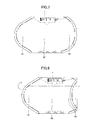
- Fig. 1 is a side view of a side airbag 101 as viewed from a given side.
- Fig. 2 is a side view of the side airbag 101 as viewed from the other side (i.e., opposite side to the given side).
- Fig. 3 is a drawing illustrating a cross-section of the side airbag 101 taken along a line A-A in Fig. 1 .
- Figs. 1 through 3 illustrate the side airbag 101 before the side airbag 101 is folded.
- the side airbag 101 is an occupant protective member having a bag shape so as to expand and to be unfolded between a side wall of a vehicle and a passenger sitting in a vehicle seat by gas supplied from an inflator 1 as will be described later.
- the side airbag 101 includes a chamber 11 formed by a panel 10 folded flat, a camber 41 formed by a panel 40 folded flat, and a protector cloth 2 that encloses the side airbag 101 in a folded state.
- Each of the panel 10, the panel 40, and the protector cloth 2 is a ground fabric having a sheet shape.
- the panel 10 has at least one passage hole 13 (see Fig. 1 and Fig. 2 ).
- the passage hole 13 is an example of an opening that enables the flow of gas from the chamber 11 to the camber 41 as the gas is supplied from the inflator 1 that will be described later.
- Fig. 1 and Fig. 2 illustrate an example in which two passage holes 13 are formed through the panel 10.
- the panel 40 has at least one vent hole 43.
- the vent hole 43 is an opening that enables the exhaustion of gas from the camber 41 to outside the camber 41.
- Fig. 1 and Fig. 2 illustrate an example in which three vent holes 43 are formed through the panel 40.
- the chamber 11 is an expansion room that is formed by the panel 10 folded flat along a fold line 12 such that a left face 20 of the panel 10 and a right face 30 of the panel 10 are placed one over another.
- the panel 10 has an outer face 16 that is a front face and an inner face 15 that is a back face.
- the panel 10 is folded flat such that the inner face 15 of the left face 20 faces the inner face 15 of the right face 30 (see Fig. 3 ).
- the chamber 41 is an expansion room that is formed by the panel 40 folded flat along a fold line 42 such that a left face 50 of the panel 40 and a right face 60 of the panel 40 are placed one over another.
- the panel 40 has an outer face 46 that is a front face and an inner face 45 that is a back face.
- the panel 40 is folded flat such that the inner face 45 of the left face 50 faces the inner face 45 of the right face 60 (see Fig. 3 ).
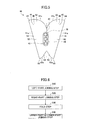
- Fig. 4 is a plan view of the panel 10 before being folded along the fold line 12 as viewed from the side where the inner face 15 is visible.
- the panel 10 has the left face 20 extending to form a semicircular shape on the left side of the fold line 12, and has the right face 30 extending to form a semicircular shape on the right side of the fold line 12.
- the left face 20 and the right face 30 are demarcated from each other by the fold line 12.
- the panel 10 has a shape that is symmetrical with respect to the fold line 12, but may not be perfectly symmetric.
- the left face 20 has an outline that is constituted by a left edge part 21, an upper edge part 22, and a lower edge part 23 while the fold line 12 constitutes a right edge part of the left face 20.
- the left edge part 21 has a contour defined by a straight line edge 21a extending in a vertical direction.
- the upper edge part 22 has a contour defined by a curved edge 22a that bulges at the center thereof toward an upper-left direction.
- the lower edge part 23 has a contour defined by a curved edge 23a that bulges at the center thereof toward a lower-left direction.
- the right face 30 has an outline that is constituted by a right edge part 31, an upper edge part 32, and a lower edge part 33 while the fold line 12 constitutes a left edge part of the right face 30.
- the right edge part 31 has a contour defined by a straight line edge 31a extending in a vertical direction.
- the upper edge part 32 has a contour defined by a curved edge 32a that bulges at the center thereof toward an upper-right direction.
- the lower edge part 33 has a contour defined by a curved edge 33a that bulges at the center thereof toward a lower-right direction.
- the panel 10 has the two passage holes 13 that are arranged in a line on, or in a line to overlap, the fold line 12.
- Each of the passage holes 13 is surrounded by an annular passage cloth 14 joined to the panel 10.
- the annular passage cloth 14 is a ground fabric having a sheet shape that is joined by sewing or the like to the inner face 15 of the panel 10 by a line-shaped double stitch 75.
- Fig. 5 is a plan view of the panel 40 before being folded along the fold line 42 as viewed from the side where the inner face 45 is visible.
- the panel 40 has the left face 50 extending to form a reversed semicircular shape on the left side of the fold line 42, and has the right face 60 extending to form a reversed semicircular shape on the right side of the fold line 42.
- the left face 50 and the right face 60 are demarcated from each other by the fold line 42.
- the panel 40 has a shape that is symmetrical with respect to the fold line 42, but may not be perfectly symmetric.
- the left face 50 has an outline that is constituted by a left edge part 51, an upper edge part 52, and a lower edge part 53 while the fold line 42 constitutes a right edge part of the left face 50.
- the left edge part 51 has a contour defined by a straight line edge 51a extending in a vertical direction.
- the upper edge part 52 has a contour defined by a curved edge 52a that bulges at the center thereof toward an upper-right direction.
- the lower edge part 53 has a contour defined by a curved edge 53a that bulges at the center thereof toward a lower-right direction.
- the right face 60 has an outline that is constituted by a right edge part 61, an upper edge part 62, and a lower edge part 63 while the fold line 42 constitutes a left edge part of the right face 60.
- the right edge part 61 has a contour defined by a straight line edge 61a extending in a vertical direction.
- the upper edge part 62 has a contour defined by a curved edge 62a that bulges at the center thereof toward an upper-left direction.
- the lower edge part 63 has a contour defined by a curved edge 63a that bulges at the center thereof toward a lower-left direction.
- the panel 40 has the three vent holes 43 that are arranged in a line on, or in a line to overlap, the fold line 42.
- Each of the vent holes 43 is surrounded by a vent cloth 44 joined to the panel 40.
- the vent cloth 44 is a ground fabric having a sheet shape that is joined by sewing or the like to the inner face 45 of the panel 40 by a line-shaped double stitch 76.
- Fig. 6 is a flowchart illustrating an example of a method of making the side airbag 101.
- the method of making the side airbag 101 includes a left-part joining step S10, a right-part joining step S20, a fold step S30, and an upper-part-&-lower-part joining step S40.
- the sequence in which the left-part joining step S10 and the right-part joining step S20 are performed may be reversed, or these two steps may be performed simultaneously.
- the left-part joining step S10 and the right-part joining step S20 serve to join the panel 10 illustrated in Fig. 4 and the panel 40 illustrated in Fig. 5 by sewing or the like.
- a worker or manufacturing apparatus joins the left face 20 and the left face 50 such that the outer face 16 of the left face 20 of the panel 10 illustrated in Fig. 4 faces the inner face 45 of the left face 50 of the panel 40 illustrated in Fig. 5 .
- the left edge part 51 of the left face 50 has a length equal to the length from a rightmost upper edge part 24 of the upper edge part 22 of the left face 20 to a rightmost lower edge part 25 of the lower edge part 23 of the left face 20.
- an upper left edge part 54 of the left face 50 is a corner at which the left edge part 51 and the upper edge part 52 come in contact with each other.
- a lower left edge part 55 of the left face 50 is a corner at which the left edge part 51 and the lower edge part 53 come in contact with each other.
- the worker or the like aligns the rightmost upper edge part 24 of the left face 20 with the upper left edge part 54 of the left face 50, and also aligns the rightmost lower edge part 25 of the left face 20 with the lower left edge part 55 of the left face 50. While keeping such an aligned state, the worker or the like joins the inner face 45 of the left edge part 51 of the left face 50 and the outer face 16 of the left face 20 along a line from the upper edge part 22 of the left face 20 to the lower edge part 23 of the left face 20 at a position nearer to the passage holes 13 than to the left edge part 21 of the left face 20.
- the worker or the like joins the inner face 45 of the left edge part 51 and the outer face 16 of the left face 20 by sewing or the like such that the edge 51a of the left edge part 51 is placed along (e.g., in parallel to) the fold line 12 in an area between the left edge part 21 and the passage holes 13.
- the left edge part 51 is joined to the outer face 16 of the left face 20 by a straight-line join part 71 extending in parallel to the fold line 12 as illustrated in Fig. 1 , for example.
- the worker or the like joins the right face 30 of the panel 10 and the right face 60 of the panel 40 such that the outer face 16 of the right face 30 of the panel 10 illustrated in Fig. 4 faces the inner face 45 of the right face 60 of the panel 40 illustrated in Fig. 5 .
- the right edge part 61 of the right face 60 has a length equal to the length from a leftmost upper edge part 34 of the upper edge part 32 of the right face 30 to a leftmost lower edge part 35 of the lower edge part 33 of the right face 30.
- an upper right edge part 64 of the right face 60 is a corner at which the right edge part 61 and the upper edge part 62 come in contact with each other.
- a lower right edge part 65 of the right face 60 is a corner at which the right edge part 61 and the lower edge part 63 come in contact with each other.
- the worker or the like aligns the leftmost upper edge part 34 of the right face 30 with the upper right edge part 64 of the right face 60, and also aligns the leftmost lower edge part 35 of the right face 30 with the lower right edge part 65 of the right face 60. While keeping such an aligned state, the worker or the like joins the inner face 45 of the right edge part 61 of the right face 60 and the outer face 16 of the right face 30 along a line from the upper edge part 32 of the right face 30 to the lower edge part 33 of the right face 30 at a position nearer to the passage holes 13 than to the right edge part 31 of the right face 30.
- the worker or the like joins the inner face 45 of the right edge part 61 and the outer face 16 of the right face 30 by sewing or the like such that the edge 61a of the right edge part 61 is placed along (e.g., in parallel to) the fold line 12 in an area between the right edge part 31 and the passage holes 13.
- the right edge part 61 is joined to the outer face 16 of the right face 30 by a straight-line join part 72 extending in parallel to the fold line 12 as illustrated in Fig. 2 , for example.
- the joined structure made of the panel 10 illustrated in Fig. 4 and the panel 40 illustrated in Fig. 5 that are joined in the left-part joining step S10 and the right-part joining step S20 is folded.
- the worker or the like places the left face 20 and the right face 30 one over the other by folding the joined structure such that the inner face 15 of the left face 20 faces the inner face 15 of the right face 30, and also places the left face 50 and the right face 60 one over the other by folding the joined structure such that the inner face 45 of the left face 50 faces the inner face 45 of the right face 60.
- the worker or the like folds the panel 10 along the fold line 12 between the left face 20 and the right face 30, and folds the panel 40 along the fold line 42 between the left face 50 and the right face 60 (see Fig. 1 and Fig. 2 )
- the upper-part-&-lower-part joining step S40 is performed after the fold step S30 to join the upper edge part 22 and the upper edge part 32, to join the lower edge part 23 and the lower edge part 33, to join the upper edge part 52 and the upper edge part 62, and to join the lower edge part 53 and the lower edge part 63 by sewing or the like.
- the worker or the like performs a joining process with respect to the panel 10 and the panel 40 such as to form the chambers 11 and 41 in the upper-part-&-lower-part joining step S40.
- an upper periphery portion constituted by the upper edge parts 22 and 32 of the panel 10 and the upper edge parts 52 and 62 of the panel 40 is sewed, and, also, a lower periphery portion constituted by the lower edge parts 23 and 33 of the panel 10 and the lower edge parts 53 and 63 of the panel 40 is sewed, with the fold line 12 of the panel 10 being covered by the panel 40 (see Fig. 1 and Fig. 2 ).
- the upper edge parts 22 and 32 of the panel 10 and the upper edge parts 52 and 62 of the panel 40 can be joined in one step by a single joining part 73, and the lower edge parts 23 and 33 of the panel 10 and the lower edge parts 53 and 63 of the panel 40 can be joined in one step by a single joining part 74.
- This arrangement thus simplifies the process of joining the upper periphery portions together and joining the lower periphery portions together with respect to the side airbag 101.
- the protector cloth 2 may be joined by the joining parts 73 and 74 to the outer face 16 of the left face 20 of the panel 10 in the upper-part-&-lower-part joining step S40.
- the left face 50 of the panel 40 has the left edge part 51 that is joined to the outer face 16 of the left face 20 along a line from the upper edge part 22 (i.e., the rightmost upper edge part 24 to be exact) to the lower edge part 23 (i.e., the rightmost lower edge part 25 to be exact) at a position closer to the fold line 12 than to the left edge part 21 of the left face 20.
- the left face 20 has an outer face portion 16a covered by the left face 50 and an outer face portion 16b exposed and not covered by the left face 50.
- the right face 60 of the panel 40 has the right edge part 61 that is joined to the outer face 16 of the right face 30 along a line from the upper edge part 32 (i.e., the leftmost upper edge part 34 to be exact) to the lower edge part 33 (i.e., the leftmost lower edge part 35 to be exact) at a position closer to the fold line 12 than to the right edge part 31 of the right face 30.
- the right face 30 has an outer face portion 16c covered by the right face 60 and an outer face portion 16d exposed and not covered by the right face 60.
- the provision of the outer face portions 16b and 16d serves to reduce the amount of the panel 40 needed for the side airbag 101 compared with the case in which the left face 20 is fully covered by the left face 50 and the right face 30 is fully covered by the right face 60.
- This arrangement also provides an advantage in that the side airbag 101 can be folded into a compact size. There is also an advantage in which the side airbag 101 can be unfolded at high speed, and the side airbag 101 can have small weight.
- the left edge part 51 extends from the upper edge part 22 to the lower edge part 23, and the right edge part 61 extends from the upper edge part 32 to the lower edge part 33, so that the exposed outer face portions 16b and 16d can be expanded to form a waist area protective surface 81.
- This arrangement ensures a high speed at which the waist area protective surface 81 is unfolded and expands.
- the waist area protective surface 81 corresponds to a lower area of the side airbag 101 in an unfolded and expanded state in a vehicle.
- a stomach area protective surface 82 corresponds to a middle area of the side airbag 101 in an unfolded and expanded state in a vehicle.
- a chest area protective surface 83 corresponds to an upper area of the side airbag 101 in an unfolded and expanded state in a vehicle.
- An area size Sb of the outer face portion 16b may be wider than an area size Sa of the outer face portion 16a, and an area size Sd of the outer face portion 16d may be wider than an area size Sc of the outer face portion 16c.
- the left edge part 51 has the upper left edge part 54 joined to the rightmost upper edge part 24 of the upper edge part 22, and also has the lower left edge part 55 joined to the rightmost lower edge part 25 of the lower edge part 23 at a position farther away from the left edge part 21 than is the upper left edge part 54.
- a distance D1 between the lower left edge part 55 and the left edge part 21 is longer than a distance D2 between the upper left edge part 54 and the left edge part 21.
- the right edge part 61 has the upper right edge part 64 joined to the leftmost upper edge part 34 of the upper edge part 32, and also has the lower right edge part 65 joined to the leftmost lower edge part 35 of the lower edge part 33 at a position farther away from the right edge part 31 than is the upper right edge part 64.
- a distance D3 between the lower right edge part 65 and the right edge part 31 is longer than a distance D4 between the upper right edge part 64 and the right edge part 31.
- the provision of the distance D1 longer than the distance D2 and the distance D3 longer than the distance D4 can further increase the area size of the outer face portions 16b and 16d exposed to form the waist area protective surface 81. This arrangement ensures a yet higher speed at which the waist area protective surface 81 is unfolded and expands.
- the left edge part 21 of the panel 10 has a plurality of mounting holes 26 arranged in a vertical direction as defined in the state in which the side airbag 101 is installed in the vehicle.
- the right edge part 31 of the panel 10 has a plurality of mounting holes 36 arranged in a vertical direction as defined in the state in which the side airbag 101 is installed in the vehicle.
- the mounting holes 26 and 36 are used to mount the inflator 1 which will be described later.
- the inflator 1 is an example of a gas supply unit (i.e., gas generator) to supply gas to the chambers 11 and 41.
- Figs. 7 through 12 illustrate an example of the procedure for folding the side airbag 101 to which the inflator 1 is mounted.
- the inflator 1 is fully inserted through an inlet 17 (see Fig. 3 ) that is formed between the line edge 21a of the left edge part 21 and the line edge 31a of the right edge part 31.
- Two mounting foot 1a (see Fig. 12 ) of the inflator 1 are inserted into the mounting holes 26b (see Figs. 1 through 3 ).
- Fig. 7 the worker or the like folds the left edge part 21 and the right edge part 31 at which the inflator 1 is mounted such that the left face 20 is placed inside when folded along a fold line parallel to the longitudinal direction of the inflator 1.
- the worker or the like folds the chest area protective surface 83 such that the right faces 30 and 60 are placed inside when folded along a fold line perpendicular to the longitudinal direction of the inflator 1.
- the worker or the like folds all of the waist area protective surface 81, the stomach area protective surface 82 and the chest area protective surface 83 such that the right face 30 is placed inside when folded along a fold line parallel to the longitudinal direction of the inflator 1. With this, the folded state as illustrated in Fig. 9 is obtained.
- Fig. 9 the worker or the like folds all of the waist area protective surface 81, the stomach area protective surface 82 and the chest area protective surface 83 such that the left face 20 is placed inside when folded along a fold line at an acute angle relative to the longitudinal direction of the inflator 1. With this, the folded state as illustrated in Fig. 10 is obtained.
- Fig. 11 the worker or the like folds the waist area protective surface 81 several times. With this, the folded state as illustrated in Fig. 12 is obtained.
- Fig. 12 illustrates the side airbag 101 that is folded with the inflator 1 enclosed therein and that is stored in a casing 3 of an airbag apparatus 201.
- the casing 3 is a housing in which the side airbag 101 folded with the inflator 1 is stored.
- the airbag apparatus 201 may be installed on a side part of the backrest of a seat such that the longitudinal direction of the inflator 1 extends in the vertical direction in the vehicle.
- the outer face portions 16b and 16d exposed at the position of the waist area protective surface 81 are relatively wide (i.e., the area size of the overlap between the panel 10 and the panel 40 at the position of the waist area protective surface 81 is relatively small), so that a height H1 of the mass of the folded waist area protective surface 81 can be made low.
- the low height H1 means that a height H2 of the casing 3 is also low, which makes it easier to secure the space for placing the airbag apparatus 201.
- all or part of the edge 51a of the left edge part 51 may be curved, and all or part of the edge 61a of the right edge part 61 may be curved. Further, all or part of the join parts 71 and 72 may be curved.
Landscapes
- Engineering & Computer Science (AREA)
- Mechanical Engineering (AREA)
- Textile Engineering (AREA)
- Air Bags (AREA)
Description
- The disclosures herein relate to a side airbag, an airbag apparatus, and a method of making a side airbag.
-
Patent Document 1, for example, discloses a side airbag. - A side airbag is stored in a casing in a folded state. The shape of a side airbag disclosed in
Patent Document 1 tends to cause the size of the side airbag in a folded state to be relatively large. Such a relatively large size of a side airbag in a folded state may cause inconvenience from the viewpoint of installment in a vehicle because of a need for a large casing, for example. - Accordingly, it may be desirable to provide a side airbag that can be folded into a compact size.
[Patent Document 1] Japanese Patent Application Publication No.2004-196162 - According to an embodiment, a side airbag includes a first panel having a first left face and a first right face, the first panel being folded along a fold line such that the first left face overlaps the first right face to form a first chamber therebetween, a second panel having a second left face and a second right face, the second panel being folded such that the second left face overlaps the second right face to form a second chamber therebetween, wherein the first panel has a hole that allows flow of gas from the first chamber to the second chamber, wherein the second left face has a second left edge part joined to the first left face along a line from a first upper edge part of the first left face to a first lower edge part of the first left face at a position closer to the fold line of the first panel than to a first left edge part of the first left face, and wherein the second right face has a second right edge part joined to the first right face along a line from a second upper edge part of the first right face to a second lower edge part of the first right face at a position closer to the fold line of the first panel than to a first right edge part of the first right face.
- According to an embodiment, a method of making a side airbag includes a left-part joining step of joining a first left face of a first panel and a second left face of a second panel by joining a second left edge part of the second left face to the first left face along a line from a first upper edge part of the first left face to a first lower edge part of the first left face at a position closer to an opening formed through the first panel than to a first left edge part of the first left face, a right-part joining step of joining a first right face of the first panel and a second right face of the second panel by joining a second right edge part of the second right face to the first right face along a line from a second upper edge part of the first right face to a second lower edge part of the first right face at a position closer to the opening formed through the first panel than to a first right edge part of the first right face, a fold step of folding the first panel and the second panel such that the first left face and the first right face overlap each other and such that the second left face and the second right face overlap each other, and a upper-part-&-lower-part joining step of joining the first upper edge part and the second upper edge part, joining the first lower edge part and the second lower edge part, joining a third upper edge part of the second left face and a fourth upper edge part of the second right face, and joining a third lower edge part of the second left face and a fourth lower edge part of the second right face.
- According to at least one embodiment, a side airbag can be folded into a compact size.
- Other objects and further features of the present invention will be apparent from the following detailed description when read in conjunction with the accompanying drawings, in which:
-
Fig. 1 is a side view of an example of a side airbag as viewed from a given side; -
Fig. 2 is a side view of the example of a side airbag as viewed from the opposite side; -
Fig. 3 is a drawing illustrating a cross-section of the side airbag taken along a line A-A inFig. 1 ; -
Fig. 4 is a plan view illustrating an example of a first panel; -
Fig. 5 is a plan view illustrating an example of a second panel; -
Fig. 6 is a flowchart illustrating an example of a method of making the side airbag; -
Fig. 7 is a drawing illustrating an example of the method of folding the side airbag; -
Fig. 8 is a drawing illustrating an example of the method of folding the side airbag; -
Fig. 9 is a drawing illustrating an example of the method of folding the side airbag; -
Fig. 10 is a drawing illustrating an example of the method of folding the side airbag; -
Fig. 11 is a drawing illustrating an example of the method of folding the side airbag; and -
Fig. 12 is a front transparent view of an example of an airbag apparatus. - In the following, embodiments of the present invention will be described with reference to the accompanying drawings.
-
Fig. 1 is a side view of aside airbag 101 as viewed from a given side.Fig. 2 is a side view of theside airbag 101 as viewed from the other side (i.e., opposite side to the given side).Fig. 3 is a drawing illustrating a cross-section of theside airbag 101 taken along a line A-A inFig. 1 .Figs. 1 through 3 illustrate theside airbag 101 before theside airbag 101 is folded. - The
side airbag 101 is an occupant protective member having a bag shape so as to expand and to be unfolded between a side wall of a vehicle and a passenger sitting in a vehicle seat by gas supplied from aninflator 1 as will be described later. Theside airbag 101 includes achamber 11 formed by apanel 10 folded flat, acamber 41 formed by apanel 40 folded flat, and aprotector cloth 2 that encloses theside airbag 101 in a folded state. - Each of the
panel 10, thepanel 40, and theprotector cloth 2 is a ground fabric having a sheet shape. Thepanel 10 has at least one passage hole 13 (seeFig. 1 andFig. 2 ). Thepassage hole 13 is an example of an opening that enables the flow of gas from thechamber 11 to thecamber 41 as the gas is supplied from theinflator 1 that will be described later.Fig. 1 andFig. 2 illustrate an example in which twopassage holes 13 are formed through thepanel 10. Thepanel 40 has at least onevent hole 43. Thevent hole 43 is an opening that enables the exhaustion of gas from thecamber 41 to outside thecamber 41.Fig. 1 andFig. 2 illustrate an example in which threevent holes 43 are formed through thepanel 40. - The
chamber 11 is an expansion room that is formed by thepanel 10 folded flat along afold line 12 such that aleft face 20 of thepanel 10 and aright face 30 of thepanel 10 are placed one over another. Thepanel 10 has anouter face 16 that is a front face and aninner face 15 that is a back face. Thepanel 10 is folded flat such that theinner face 15 of theleft face 20 faces theinner face 15 of the right face 30 (seeFig. 3 ). - The
chamber 41 is an expansion room that is formed by thepanel 40 folded flat along afold line 42 such that aleft face 50 of thepanel 40 and aright face 60 of thepanel 40 are placed one over another. Thepanel 40 has anouter face 46 that is a front face and aninner face 45 that is a back face. Thepanel 40 is folded flat such that theinner face 45 of theleft face 50 faces theinner face 45 of the right face 60 (seeFig. 3 ). -
Fig. 4 is a plan view of thepanel 10 before being folded along thefold line 12 as viewed from the side where theinner face 15 is visible. Thepanel 10 has theleft face 20 extending to form a semicircular shape on the left side of thefold line 12, and has theright face 30 extending to form a semicircular shape on the right side of thefold line 12. Theleft face 20 and theright face 30 are demarcated from each other by thefold line 12. Thepanel 10 has a shape that is symmetrical with respect to thefold line 12, but may not be perfectly symmetric. - The
left face 20 has an outline that is constituted by aleft edge part 21, anupper edge part 22, and alower edge part 23 while thefold line 12 constitutes a right edge part of theleft face 20. Theleft edge part 21 has a contour defined by astraight line edge 21a extending in a vertical direction. Theupper edge part 22 has a contour defined by acurved edge 22a that bulges at the center thereof toward an upper-left direction. Thelower edge part 23 has a contour defined by acurved edge 23a that bulges at the center thereof toward a lower-left direction. - The
right face 30 has an outline that is constituted by aright edge part 31, anupper edge part 32, and alower edge part 33 while thefold line 12 constitutes a left edge part of theright face 30. Theright edge part 31 has a contour defined by astraight line edge 31a extending in a vertical direction. Theupper edge part 32 has a contour defined by acurved edge 32a that bulges at the center thereof toward an upper-right direction. Thelower edge part 33 has a contour defined by acurved edge 33a that bulges at the center thereof toward a lower-right direction. - The
panel 10 has the twopassage holes 13 that are arranged in a line on, or in a line to overlap, thefold line 12. Each of thepassage holes 13 is surrounded by anannular passage cloth 14 joined to thepanel 10. Theannular passage cloth 14 is a ground fabric having a sheet shape that is joined by sewing or the like to theinner face 15 of thepanel 10 by a line-shapeddouble stitch 75. -
Fig. 5 is a plan view of thepanel 40 before being folded along thefold line 42 as viewed from the side where theinner face 45 is visible. Thepanel 40 has theleft face 50 extending to form a reversed semicircular shape on the left side of thefold line 42, and has theright face 60 extending to form a reversed semicircular shape on the right side of thefold line 42. Theleft face 50 and theright face 60 are demarcated from each other by thefold line 42. Thepanel 40 has a shape that is symmetrical with respect to thefold line 42, but may not be perfectly symmetric. - The
left face 50 has an outline that is constituted by aleft edge part 51, anupper edge part 52, and alower edge part 53 while thefold line 42 constitutes a right edge part of theleft face 50. Theleft edge part 51 has a contour defined by astraight line edge 51a extending in a vertical direction. Theupper edge part 52 has a contour defined by acurved edge 52a that bulges at the center thereof toward an upper-right direction. Thelower edge part 53 has a contour defined by acurved edge 53a that bulges at the center thereof toward a lower-right direction. - The
right face 60 has an outline that is constituted by aright edge part 61, anupper edge part 62, and alower edge part 63 while thefold line 42 constitutes a left edge part of theright face 60. Theright edge part 61 has a contour defined by astraight line edge 61a extending in a vertical direction. Theupper edge part 62 has a contour defined by acurved edge 62a that bulges at the center thereof toward an upper-left direction. Thelower edge part 63 has a contour defined by a curved edge 63a that bulges at the center thereof toward a lower-left direction. - The
panel 40 has the threevent holes 43 that are arranged in a line on, or in a line to overlap, thefold line 42. Each of the vent holes 43 is surrounded by avent cloth 44 joined to thepanel 40. Thevent cloth 44 is a ground fabric having a sheet shape that is joined by sewing or the like to theinner face 45 of thepanel 40 by a line-shapeddouble stitch 76. -
Fig. 6 is a flowchart illustrating an example of a method of making theside airbag 101. The method of making theside airbag 101 includes a left-part joining step S10, a right-part joining step S20, a fold step S30, and an upper-part-&-lower-part joining step S40. The sequence in which the left-part joining step S10 and the right-part joining step S20 are performed may be reversed, or these two steps may be performed simultaneously. - The left-part joining step S10 and the right-part joining step S20 serve to join the
panel 10 illustrated inFig. 4 and thepanel 40 illustrated inFig. 5 by sewing or the like. - In the left-part joining step S10, a worker or manufacturing apparatus (which will hereinafter be referred to collectively as "worker or the like") joins the
left face 20 and theleft face 50 such that theouter face 16 of theleft face 20 of thepanel 10 illustrated inFig. 4 faces theinner face 45 of theleft face 50 of thepanel 40 illustrated inFig. 5 . Theleft edge part 51 of theleft face 50 has a length equal to the length from a rightmostupper edge part 24 of theupper edge part 22 of theleft face 20 to a rightmostlower edge part 25 of thelower edge part 23 of theleft face 20. Further, an upperleft edge part 54 of theleft face 50 is a corner at which theleft edge part 51 and theupper edge part 52 come in contact with each other. A lowerleft edge part 55 of theleft face 50 is a corner at which theleft edge part 51 and thelower edge part 53 come in contact with each other. The worker or the like aligns the rightmostupper edge part 24 of theleft face 20 with the upperleft edge part 54 of theleft face 50, and also aligns the rightmostlower edge part 25 of theleft face 20 with the lowerleft edge part 55 of theleft face 50. While keeping such an aligned state, the worker or the like joins theinner face 45 of theleft edge part 51 of theleft face 50 and theouter face 16 of theleft face 20 along a line from theupper edge part 22 of theleft face 20 to thelower edge part 23 of theleft face 20 at a position nearer to the passage holes 13 than to theleft edge part 21 of theleft face 20. - The worker or the like joins the
inner face 45 of theleft edge part 51 and theouter face 16 of theleft face 20 by sewing or the like such that theedge 51a of theleft edge part 51 is placed along (e.g., in parallel to) thefold line 12 in an area between theleft edge part 21 and the passage holes 13. As a result, theleft edge part 51 is joined to theouter face 16 of theleft face 20 by a straight-line join part 71 extending in parallel to thefold line 12 as illustrated inFig. 1 , for example. - In the right-part joining step S20, the worker or the like joins the
right face 30 of thepanel 10 and theright face 60 of thepanel 40 such that theouter face 16 of theright face 30 of thepanel 10 illustrated inFig. 4 faces theinner face 45 of theright face 60 of thepanel 40 illustrated inFig. 5 . Theright edge part 61 of theright face 60 has a length equal to the length from a leftmostupper edge part 34 of theupper edge part 32 of theright face 30 to a leftmostlower edge part 35 of thelower edge part 33 of theright face 30. Further, an upperright edge part 64 of theright face 60 is a corner at which theright edge part 61 and theupper edge part 62 come in contact with each other. A lowerright edge part 65 of theright face 60 is a corner at which theright edge part 61 and thelower edge part 63 come in contact with each other. The worker or the like aligns the leftmostupper edge part 34 of theright face 30 with the upperright edge part 64 of theright face 60, and also aligns the leftmostlower edge part 35 of theright face 30 with the lowerright edge part 65 of theright face 60. While keeping such an aligned state, the worker or the like joins theinner face 45 of theright edge part 61 of theright face 60 and theouter face 16 of theright face 30 along a line from theupper edge part 32 of theright face 30 to thelower edge part 33 of theright face 30 at a position nearer to the passage holes 13 than to theright edge part 31 of theright face 30. - The worker or the like joins the
inner face 45 of theright edge part 61 and theouter face 16 of theright face 30 by sewing or the like such that theedge 61a of theright edge part 61 is placed along (e.g., in parallel to) thefold line 12 in an area between theright edge part 31 and the passage holes 13. As a result, theright edge part 61 is joined to theouter face 16 of theright face 30 by a straight-line join part 72 extending in parallel to thefold line 12 as illustrated inFig. 2 , for example. - In the fold step S30, the joined structure made of the
panel 10 illustrated inFig. 4 and thepanel 40 illustrated inFig. 5 that are joined in the left-part joining step S10 and the right-part joining step S20 is folded. The worker or the like places theleft face 20 and theright face 30 one over the other by folding the joined structure such that theinner face 15 of theleft face 20 faces theinner face 15 of theright face 30, and also places theleft face 50 and theright face 60 one over the other by folding the joined structure such that theinner face 45 of theleft face 50 faces theinner face 45 of theright face 60. The worker or the like folds thepanel 10 along thefold line 12 between theleft face 20 and theright face 30, and folds thepanel 40 along thefold line 42 between theleft face 50 and the right face 60 (seeFig. 1 andFig. 2 ) - The upper-part-&-lower-part joining step S40 is performed after the fold step S30 to join the
upper edge part 22 and theupper edge part 32, to join thelower edge part 23 and thelower edge part 33, to join theupper edge part 52 and theupper edge part 62, and to join thelower edge part 53 and thelower edge part 63 by sewing or the like. The worker or the like performs a joining process with respect to thepanel 10 and thepanel 40 such as to form thechambers - In the upper-part-&-lower-part joining step S40, an upper periphery portion constituted by the
upper edge parts panel 10 and theupper edge parts panel 40 is sewed, and, also, a lower periphery portion constituted by thelower edge parts panel 10 and thelower edge parts panel 40 is sewed, with thefold line 12 of thepanel 10 being covered by the panel 40 (seeFig. 1 andFig. 2 ). As a result of such a sewing process, theupper edge parts panel 10 and theupper edge parts panel 40 can be joined in one step by a single joiningpart 73, and thelower edge parts panel 10 and thelower edge parts panel 40 can be joined in one step by a single joiningpart 74. This arrangement thus simplifies the process of joining the upper periphery portions together and joining the lower periphery portions together with respect to theside airbag 101. - Through the steps described above, the
side airbag 101 as illustrated inFig. 1 through Fig. 3 is made. Theprotector cloth 2 may be joined by the joiningparts outer face 16 of theleft face 20 of thepanel 10 in the upper-part-&-lower-part joining step S40. - As illustrated in
Fig. 1 , theleft face 50 of thepanel 40 has theleft edge part 51 that is joined to theouter face 16 of theleft face 20 along a line from the upper edge part 22 (i.e., the rightmostupper edge part 24 to be exact) to the lower edge part 23 (i.e., the rightmostlower edge part 25 to be exact) at a position closer to thefold line 12 than to theleft edge part 21 of theleft face 20. Namely, theleft face 20 has anouter face portion 16a covered by theleft face 50 and anouter face portion 16b exposed and not covered by theleft face 50. - As illustrated in
Fig. 2 , theright face 60 of thepanel 40 has theright edge part 61 that is joined to theouter face 16 of theright face 30 along a line from the upper edge part 32 (i.e., the leftmostupper edge part 34 to be exact) to the lower edge part 33 (i.e., the leftmostlower edge part 35 to be exact) at a position closer to thefold line 12 than to theright edge part 31 of theright face 30. Namely, theright face 30 has anouter face portion 16c covered by theright face 60 and anouter face portion 16d exposed and not covered by theright face 60. - The provision of the
outer face portions panel 40 needed for theside airbag 101 compared with the case in which theleft face 20 is fully covered by theleft face 50 and theright face 30 is fully covered by theright face 60. This arrangement also provides an advantage in that theside airbag 101 can be folded into a compact size. There is also an advantage in which theside airbag 101 can be unfolded at high speed, and theside airbag 101 can have small weight. - As illustrated in
Fig. 1 andFig. 2 , theleft edge part 51 extends from theupper edge part 22 to thelower edge part 23, and theright edge part 61 extends from theupper edge part 32 to thelower edge part 33, so that the exposedouter face portions protective surface 81. This arrangement ensures a high speed at which the waist areaprotective surface 81 is unfolded and expands. - The waist area
protective surface 81 corresponds to a lower area of theside airbag 101 in an unfolded and expanded state in a vehicle. A stomach areaprotective surface 82 corresponds to a middle area of theside airbag 101 in an unfolded and expanded state in a vehicle. A chest areaprotective surface 83 corresponds to an upper area of theside airbag 101 in an unfolded and expanded state in a vehicle. - An area size Sb of the
outer face portion 16b may be wider than an area size Sa of theouter face portion 16a, and an area size Sd of theouter face portion 16d may be wider than an area size Sc of theouter face portion 16c. Such an arrangement ensures that theside airbag 101 can be folded into a more compact size. - The
left edge part 51 has the upperleft edge part 54 joined to the rightmostupper edge part 24 of theupper edge part 22, and also has the lowerleft edge part 55 joined to the rightmostlower edge part 25 of thelower edge part 23 at a position farther away from theleft edge part 21 than is the upperleft edge part 54. Namely, a distance D1 between the lowerleft edge part 55 and theleft edge part 21 is longer than a distance D2 between the upperleft edge part 54 and theleft edge part 21. Similarly, theright edge part 61 has the upperright edge part 64 joined to the leftmostupper edge part 34 of theupper edge part 32, and also has the lowerright edge part 65 joined to the leftmostlower edge part 35 of thelower edge part 33 at a position farther away from theright edge part 31 than is the upperright edge part 64. Namely, a distance D3 between the lowerright edge part 65 and theright edge part 31 is longer than a distance D4 between the upperright edge part 64 and theright edge part 31. - The provision of the distance D1 longer than the distance D2 and the distance D3 longer than the distance D4 can further increase the area size of the
outer face portions protective surface 81. This arrangement ensures a yet higher speed at which the waist areaprotective surface 81 is unfolded and expands. - As illustrated in
Fig. 1 , theleft edge part 21 of thepanel 10 has a plurality of mountingholes 26 arranged in a vertical direction as defined in the state in which theside airbag 101 is installed in the vehicle. As illustrated inFig. 2 , theright edge part 31 of thepanel 10 has a plurality of mountingholes 36 arranged in a vertical direction as defined in the state in which theside airbag 101 is installed in the vehicle. The mounting holes 26 and 36 are used to mount theinflator 1 which will be described later. Theinflator 1 is an example of a gas supply unit (i.e., gas generator) to supply gas to thechambers -
Figs. 7 through 12 illustrate an example of the procedure for folding theside airbag 101 to which theinflator 1 is mounted. - In
Fig. 7 , theinflator 1 is fully inserted through an inlet 17 (seeFig. 3 ) that is formed between theline edge 21a of theleft edge part 21 and theline edge 31a of theright edge part 31. Two mountingfoot 1a (seeFig. 12 ) of theinflator 1 are inserted into the mountingholes 26b (seeFigs. 1 through 3 ). - In
Fig. 7 , the worker or the like folds theleft edge part 21 and theright edge part 31 at which theinflator 1 is mounted such that theleft face 20 is placed inside when folded along a fold line parallel to the longitudinal direction of theinflator 1. - In
Fig. 8 , the worker or the like folds the chest areaprotective surface 83 such that the right faces 30 and 60 are placed inside when folded along a fold line perpendicular to the longitudinal direction of theinflator 1. After folding the chest areaprotective surface 83, the worker or the like folds all of the waist areaprotective surface 81, the stomach areaprotective surface 82 and the chest areaprotective surface 83 such that theright face 30 is placed inside when folded along a fold line parallel to the longitudinal direction of theinflator 1. With this, the folded state as illustrated inFig. 9 is obtained. - In
Fig. 9 , the worker or the like folds all of the waist areaprotective surface 81, the stomach areaprotective surface 82 and the chest areaprotective surface 83 such that theleft face 20 is placed inside when folded along a fold line at an acute angle relative to the longitudinal direction of theinflator 1. With this, the folded state as illustrated inFig. 10 is obtained. - In
Fig. 10 , the worker or the like rolls up the stomach areaprotective surface 82 several turns. With this, the folded state as illustrated inFig. 11 is obtained. - In
Fig. 11 , the worker or the like folds the waist areaprotective surface 81 several times. With this, the folded state as illustrated inFig. 12 is obtained. -
Fig. 12 illustrates theside airbag 101 that is folded with theinflator 1 enclosed therein and that is stored in acasing 3 of anairbag apparatus 201. Thecasing 3 is a housing in which theside airbag 101 folded with theinflator 1 is stored. Theairbag apparatus 201 may be installed on a side part of the backrest of a seat such that the longitudinal direction of theinflator 1 extends in the vertical direction in the vehicle. - As was described above, the
outer face portions protective surface 81 are relatively wide (i.e., the area size of the overlap between thepanel 10 and thepanel 40 at the position of the waist areaprotective surface 81 is relatively small), so that a height H1 of the mass of the folded waist areaprotective surface 81 can be made low. The low height H1 means that a height H2 of thecasing 3 is also low, which makes it easier to secure the space for placing theairbag apparatus 201. - Although the side airbag, the airbag apparatus, and the method of making the side airbag have been described heretofore with reference to particular embodiments, the present invention is not limited to those embodiments. Various modifications and improvements such as combining an embodiment partially or entirely with one or more other embodiments or replacing part of an embodiment with part of another embodiment may be made without departing from the scope of the present invention.
- For example, all or part of the
edge 51a of theleft edge part 51 may be curved, and all or part of theedge 61a of theright edge part 61 may be curved. Further, all or part of thejoin parts
Claims (8)
- A side airbag, comprising:a first panel having a first left face and a first right face, the first panel being folded along a fold line such that the first left face overlaps the first right face to form a first chamber therebetween;a second panel having a second left face and a second right face, the second panel being folded such that the second left face overlaps the second right face to form a second chamber therebetween;wherein the first panel has a hole that allows flow of gas from the first chamber to the second chamber,wherein the second left face has a second left edge part joined to the first left face along a line from a first upper edge part of the first left face to a first lower edge part of the first left face at a position closer to the fold line of the first panel than to a first left edge part of the first left face, andwherein the second right face has a second right edge part joined to the first right face along a line from a second upper edge part of the first right face to a second lower edge part of the first right face at a position closer to the fold line of the first panel than to a first right edge part of the first right face.
- The side airbag as claimed in claim 1, wherein the second left edge part has an upper left edge part joined to the first upper edge part, and has a lower left edge part joined to the first lower edge part at a position farther away from the first left edge part than is the upper left edge part, and the second right edge part has an upper right edge part joined to the second upper edge part, and has a lower right edge part joined to the second lower edge part at a position farther away from the first right edge part than is the upper right edge part.
- The side airbag as claimed in claim 1 or 2, wherein an area size of a portion of the first left face that is not covered by the second left face is wider than an area size of a portion of the first left face that is covered by the second left face, and wherein an area size of a portion of the first right face that is not covered by the second right face is wider than an area size of a portion of the first right face that is covered by the second right face.
- The side airbag as claimed in any one of claims 1 to 3, wherein the second left edge part is joined to the fist left face along the fold line, and the second right edge part is joined to the fist right face along the fold line.
- The side airbag as claimed in any one of claims 1 to 4, wherein the first left edge part and the first right edge part have mounting holes for mounting a gas supply unit that supplies the gas.
- An airbag apparatus, comprising:the side airbag of any one of claims 1 to 5;a gas supply unit configured to supply the gas; anda casing configured to accommodate the side airbag and the gas supply unit.
- A method of making a side airbag, comprising:a left-part joining step of joining a first left face of a first panel and a second left face of a second panel by joining a second left edge part of the second left face to the first left face along a line from a first upper edge part of the first left face to a first lower edge part of the first left face at a position closer to an opening formed through the first panel than to a first left edge part of the first left face;a right-part joining step of joining a first right face of the first panel and a second right face of the second panel by joining a second right edge part of the second right face to the first right face along a line from a second upper edge part of the first right face to a second lower edge part of the first right face at a position closer to the opening formed through the first panel than to a first right edge part of the first right face;a fold step of folding the first panel and the second panel such that the first left face and the first right face overlap each other and such that the second left face and the second right face overlap each other; anda upper-part-and-lower-part joining step of joining the first upper edge part and the second upper edge part, joining the first lower edge part and the second lower edge part, joining a third upper edge part of the second left face and a fourth upper edge part of the second right face, and joining a third lower edge part of the second left face and a fourth lower edge part of the second right face.
- The method as claimed in claim 7, wherein the upper-part-and-lower-part joining step is performed by sewing an upper periphery portion constituted by the upper edge parts of the first panel and the upper edge parts of the second panel and sewing a lower periphery portion constituted by the lower edge parts of the first panel and the lower edge parts of the second panel, with the fold line of the first panel being covered by the second panel.
Applications Claiming Priority (1)
| Application Number | Priority Date | Filing Date | Title |
|---|---|---|---|
| JP2013272773A JP2015127168A (en) | 2013-12-27 | 2013-12-27 | Side airbag, airbag device, and method of manufacturing side airbag |
Publications (2)
| Publication Number | Publication Date |
|---|---|
| EP2889190A1 true EP2889190A1 (en) | 2015-07-01 |
| EP2889190B1 EP2889190B1 (en) | 2017-02-08 |
Family
ID=52282488
Family Applications (1)
| Application Number | Title | Priority Date | Filing Date |
|---|---|---|---|
| EP14199672.8A Not-in-force EP2889190B1 (en) | 2013-12-27 | 2014-12-22 | Side airbag, airbag apparatus, method of making side airbag |
Country Status (4)
| Country | Link |
|---|---|
| US (1) | US9340175B2 (en) |
| EP (1) | EP2889190B1 (en) |
| JP (1) | JP2015127168A (en) |
| CN (1) | CN104742850B (en) |
Families Citing this family (2)
| Publication number | Priority date | Publication date | Assignee | Title |
|---|---|---|---|---|
| US9834168B2 (en) * | 2015-09-16 | 2017-12-05 | Ford Global Technologies, Llc | Side airbag including forward facing vent |
| JP2024061008A (en) * | 2022-10-20 | 2024-05-07 | 株式会社Subaru | Air bag device |
Citations (4)
| Publication number | Priority date | Publication date | Assignee | Title |
|---|---|---|---|---|
| EP1273486A2 (en) * | 2001-07-03 | 2003-01-08 | Delphi Automotive Systems Sungwoo Co., Ltd. | Side airbag for automobile and method of folding the same |
| WO2003101788A1 (en) * | 2002-05-28 | 2003-12-11 | Takata Corporation | Multipart airbag cutting for an airbag of an occupant protection device for motor vehicles and method for producing an airbag from said airbag cutting |
| JP2004196162A (en) | 2002-12-19 | 2004-07-15 | Takata Corp | Side air bag |
| DE102010018180A1 (en) * | 2010-04-22 | 2011-10-27 | Autoliv Development Ab | Airbag with a first side wall and a second side wall and at least one tether |
Family Cites Families (7)
| Publication number | Priority date | Publication date | Assignee | Title |
|---|---|---|---|---|
| JP2858670B2 (en) | 1990-10-25 | 1999-02-17 | 松下電器産業株式会社 | Oil burning equipment |
| JP3411524B2 (en) * | 1999-05-26 | 2003-06-03 | 日本プラスト株式会社 | Automotive side airbag device |
| GB2419116A (en) * | 2004-10-13 | 2006-04-19 | Autoliv Dev | A side air-bag with distinct head and thorax regions |
| DE102005043308B4 (en) * | 2005-09-07 | 2010-09-23 | Takata-Petri Ag | Airbag, in particular for the protection of the knee area of a vehicle occupant |
| JP4992790B2 (en) * | 2008-03-28 | 2012-08-08 | 豊田合成株式会社 | Crew protection device |
| JP2011105186A (en) * | 2009-11-18 | 2011-06-02 | Nippon Plast Co Ltd | Air-bag |
| US8480124B2 (en) | 2011-01-18 | 2013-07-09 | Autoliv Asp, Inc. | Seat bolster chamber |
-
2013
- 2013-12-27 JP JP2013272773A patent/JP2015127168A/en active Pending
-
2014
- 2014-12-16 US US14/571,516 patent/US9340175B2/en active Active
- 2014-12-22 EP EP14199672.8A patent/EP2889190B1/en not_active Not-in-force
- 2014-12-26 CN CN201410834780.XA patent/CN104742850B/en not_active Expired - Fee Related
Patent Citations (4)
| Publication number | Priority date | Publication date | Assignee | Title |
|---|---|---|---|---|
| EP1273486A2 (en) * | 2001-07-03 | 2003-01-08 | Delphi Automotive Systems Sungwoo Co., Ltd. | Side airbag for automobile and method of folding the same |
| WO2003101788A1 (en) * | 2002-05-28 | 2003-12-11 | Takata Corporation | Multipart airbag cutting for an airbag of an occupant protection device for motor vehicles and method for producing an airbag from said airbag cutting |
| JP2004196162A (en) | 2002-12-19 | 2004-07-15 | Takata Corp | Side air bag |
| DE102010018180A1 (en) * | 2010-04-22 | 2011-10-27 | Autoliv Development Ab | Airbag with a first side wall and a second side wall and at least one tether |
Also Published As
| Publication number | Publication date |
|---|---|
| CN104742850B (en) | 2018-10-16 |
| US9340175B2 (en) | 2016-05-17 |
| JP2015127168A (en) | 2015-07-09 |
| EP2889190B1 (en) | 2017-02-08 |
| CN104742850A (en) | 2015-07-01 |
| US20150183394A1 (en) | 2015-07-02 |
Similar Documents
| Publication | Publication Date | Title |
|---|---|---|
| JP5021746B2 (en) | Side airbag module | |
| CN102666214B (en) | The inflatable knee airbag with continuous cavity that low level is installed | |
| US20100181749A1 (en) | Side airbag and side airbag device | |
| US20100117343A1 (en) | Air bag | |
| US9290149B2 (en) | Airbag apparatus for a front passenger seat | |
| WO2011077510A1 (en) | Side airbag device and method of sewing side airbag | |
| JP2009023640A (en) | Multi-chamber type side air bag | |
| US10525924B2 (en) | Occupant leg restraint device | |
| JP2018167793A (en) | Air bag device | |
| CN102407823A (en) | Airbag, airbag apparatus and tether sewing method | |
| CN106004773A (en) | Knee-protecting airbag device | |
| JP2018167794A (en) | Airbag device | |
| EP2889190B1 (en) | Side airbag, airbag apparatus, method of making side airbag | |
| JP2011207428A (en) | Airbag | |
| CN212709304U (en) | side airbag equipment | |
| JP2006137414A (en) | Airbag system | |
| CN115476806B (en) | Driver's airbag device | |
| JP2014166785A (en) | Air bag device | |
| JP6058338B2 (en) | Airbag device | |
| JP4992799B2 (en) | Side airbag device | |
| KR102558598B1 (en) | Nee airbag apparatus and manufacturing method thereof | |
| JP2015067016A (en) | Air bag | |
| JP5656787B2 (en) | Side airbag for vehicle | |
| JP6467883B2 (en) | Side airbag device | |
| CN102514539A (en) | Supporting ring and automobile safety airbag |
Legal Events
| Date | Code | Title | Description |
|---|---|---|---|
| PUAI | Public reference made under article 153(3) epc to a published international application that has entered the european phase |
Free format text: ORIGINAL CODE: 0009012 |
|
| 17P | Request for examination filed |
Effective date: 20141222 |
|
| AK | Designated contracting states |
Kind code of ref document: A1 Designated state(s): AL AT BE BG CH CY CZ DE DK EE ES FI FR GB GR HR HU IE IS IT LI LT LU LV MC MK MT NL NO PL PT RO RS SE SI SK SM TR |
|
| AX | Request for extension of the european patent |
Extension state: BA ME |
|
| R17P | Request for examination filed (corrected) |
Effective date: 20151021 |
|
| RBV | Designated contracting states (corrected) |
Designated state(s): AL AT BE BG CH CY CZ DE DK EE ES FI FR GB GR HR HU IE IS IT LI LT LU LV MC MK MT NL NO PL PT RO RS SE SI SK SM TR |
|
| GRAP | Despatch of communication of intention to grant a patent |
Free format text: ORIGINAL CODE: EPIDOSNIGR1 |
|
| INTG | Intention to grant announced |
Effective date: 20160913 |
|
| RIN1 | Information on inventor provided before grant (corrected) |
Inventor name: YUKI, TATSUYA Inventor name: YOKOTA, MASASHI |
|
| GRAS | Grant fee paid |
Free format text: ORIGINAL CODE: EPIDOSNIGR3 |
|
| GRAA | (expected) grant |
Free format text: ORIGINAL CODE: 0009210 |
|
| RIN1 | Information on inventor provided before grant (corrected) |
Inventor name: YUKI, TATSUYA Inventor name: YOKOTA, MASATOSHI |
|
| AK | Designated contracting states |
Kind code of ref document: B1 Designated state(s): AL AT BE BG CH CY CZ DE DK EE ES FI FR GB GR HR HU IE IS IT LI LT LU LV MC MK MT NL NO PL PT RO RS SE SI SK SM TR |
|
| REG | Reference to a national code |
Ref country code: GB Ref legal event code: FG4D |
|
| REG | Reference to a national code |
Ref country code: CH Ref legal event code: EP Ref country code: AT Ref legal event code: REF Ref document number: 866720 Country of ref document: AT Kind code of ref document: T Effective date: 20170215 |
|
| REG | Reference to a national code |
Ref country code: IE Ref legal event code: FG4D |
|
| REG | Reference to a national code |
Ref country code: DE Ref legal event code: R096 Ref document number: 602014006712 Country of ref document: DE |
|
| REG | Reference to a national code |
Ref country code: LT Ref legal event code: MG4D |
|
| REG | Reference to a national code |
Ref country code: NL Ref legal event code: MP Effective date: 20170208 |
|
| REG | Reference to a national code |
Ref country code: AT Ref legal event code: MK05 Ref document number: 866720 Country of ref document: AT Kind code of ref document: T Effective date: 20170208 |
|
| PG25 | Lapsed in a contracting state [announced via postgrant information from national office to epo] |
Ref country code: LT Free format text: LAPSE BECAUSE OF FAILURE TO SUBMIT A TRANSLATION OF THE DESCRIPTION OR TO PAY THE FEE WITHIN THE PRESCRIBED TIME-LIMIT Effective date: 20170208 Ref country code: NO Free format text: LAPSE BECAUSE OF FAILURE TO SUBMIT A TRANSLATION OF THE DESCRIPTION OR TO PAY THE FEE WITHIN THE PRESCRIBED TIME-LIMIT Effective date: 20170508 Ref country code: FI Free format text: LAPSE BECAUSE OF FAILURE TO SUBMIT A TRANSLATION OF THE DESCRIPTION OR TO PAY THE FEE WITHIN THE PRESCRIBED TIME-LIMIT Effective date: 20170208 Ref country code: GR Free format text: LAPSE BECAUSE OF FAILURE TO SUBMIT A TRANSLATION OF THE DESCRIPTION OR TO PAY THE FEE WITHIN THE PRESCRIBED TIME-LIMIT Effective date: 20170509 Ref country code: HR Free format text: LAPSE BECAUSE OF FAILURE TO SUBMIT A TRANSLATION OF THE DESCRIPTION OR TO PAY THE FEE WITHIN THE PRESCRIBED TIME-LIMIT Effective date: 20170208 |
|
| PG25 | Lapsed in a contracting state [announced via postgrant information from national office to epo] |
Ref country code: PT Free format text: LAPSE BECAUSE OF FAILURE TO SUBMIT A TRANSLATION OF THE DESCRIPTION OR TO PAY THE FEE WITHIN THE PRESCRIBED TIME-LIMIT Effective date: 20170608 Ref country code: RS Free format text: LAPSE BECAUSE OF FAILURE TO SUBMIT A TRANSLATION OF THE DESCRIPTION OR TO PAY THE FEE WITHIN THE PRESCRIBED TIME-LIMIT Effective date: 20170208 Ref country code: SE Free format text: LAPSE BECAUSE OF FAILURE TO SUBMIT A TRANSLATION OF THE DESCRIPTION OR TO PAY THE FEE WITHIN THE PRESCRIBED TIME-LIMIT Effective date: 20170208 Ref country code: NL Free format text: LAPSE BECAUSE OF FAILURE TO SUBMIT A TRANSLATION OF THE DESCRIPTION OR TO PAY THE FEE WITHIN THE PRESCRIBED TIME-LIMIT Effective date: 20170208 Ref country code: AT Free format text: LAPSE BECAUSE OF FAILURE TO SUBMIT A TRANSLATION OF THE DESCRIPTION OR TO PAY THE FEE WITHIN THE PRESCRIBED TIME-LIMIT Effective date: 20170208 Ref country code: LV Free format text: LAPSE BECAUSE OF FAILURE TO SUBMIT A TRANSLATION OF THE DESCRIPTION OR TO PAY THE FEE WITHIN THE PRESCRIBED TIME-LIMIT Effective date: 20170208 Ref country code: BG Free format text: LAPSE BECAUSE OF FAILURE TO SUBMIT A TRANSLATION OF THE DESCRIPTION OR TO PAY THE FEE WITHIN THE PRESCRIBED TIME-LIMIT Effective date: 20170508 Ref country code: ES Free format text: LAPSE BECAUSE OF FAILURE TO SUBMIT A TRANSLATION OF THE DESCRIPTION OR TO PAY THE FEE WITHIN THE PRESCRIBED TIME-LIMIT Effective date: 20170208 |
|
| PG25 | Lapsed in a contracting state [announced via postgrant information from national office to epo] |
Ref country code: EE Free format text: LAPSE BECAUSE OF FAILURE TO SUBMIT A TRANSLATION OF THE DESCRIPTION OR TO PAY THE FEE WITHIN THE PRESCRIBED TIME-LIMIT Effective date: 20170208 Ref country code: CZ Free format text: LAPSE BECAUSE OF FAILURE TO SUBMIT A TRANSLATION OF THE DESCRIPTION OR TO PAY THE FEE WITHIN THE PRESCRIBED TIME-LIMIT Effective date: 20170208 Ref country code: SK Free format text: LAPSE BECAUSE OF FAILURE TO SUBMIT A TRANSLATION OF THE DESCRIPTION OR TO PAY THE FEE WITHIN THE PRESCRIBED TIME-LIMIT Effective date: 20170208 Ref country code: RO Free format text: LAPSE BECAUSE OF FAILURE TO SUBMIT A TRANSLATION OF THE DESCRIPTION OR TO PAY THE FEE WITHIN THE PRESCRIBED TIME-LIMIT Effective date: 20170208 Ref country code: IT Free format text: LAPSE BECAUSE OF FAILURE TO SUBMIT A TRANSLATION OF THE DESCRIPTION OR TO PAY THE FEE WITHIN THE PRESCRIBED TIME-LIMIT Effective date: 20170208 |
|
| REG | Reference to a national code |
Ref country code: DE Ref legal event code: R097 Ref document number: 602014006712 Country of ref document: DE |
|
| PG25 | Lapsed in a contracting state [announced via postgrant information from national office to epo] |
Ref country code: DK Free format text: LAPSE BECAUSE OF FAILURE TO SUBMIT A TRANSLATION OF THE DESCRIPTION OR TO PAY THE FEE WITHIN THE PRESCRIBED TIME-LIMIT Effective date: 20170208 Ref country code: SM Free format text: LAPSE BECAUSE OF FAILURE TO SUBMIT A TRANSLATION OF THE DESCRIPTION OR TO PAY THE FEE WITHIN THE PRESCRIBED TIME-LIMIT Effective date: 20170208 Ref country code: PL Free format text: LAPSE BECAUSE OF FAILURE TO SUBMIT A TRANSLATION OF THE DESCRIPTION OR TO PAY THE FEE WITHIN THE PRESCRIBED TIME-LIMIT Effective date: 20170208 |
|
| PLBE | No opposition filed within time limit |
Free format text: ORIGINAL CODE: 0009261 |
|
| STAA | Information on the status of an ep patent application or granted ep patent |
Free format text: STATUS: NO OPPOSITION FILED WITHIN TIME LIMIT |
|
| 26N | No opposition filed |
Effective date: 20171109 |
|
| PG25 | Lapsed in a contracting state [announced via postgrant information from national office to epo] |
Ref country code: SI Free format text: LAPSE BECAUSE OF FAILURE TO SUBMIT A TRANSLATION OF THE DESCRIPTION OR TO PAY THE FEE WITHIN THE PRESCRIBED TIME-LIMIT Effective date: 20170208 |
|
| REG | Reference to a national code |
Ref country code: DE Ref legal event code: R081 Ref document number: 602014006712 Country of ref document: DE Owner name: JOYSON SAFETY SYSTEMS JAPAN G.K., JP Free format text: FORMER OWNER: TAKATA CORPORATION, TOKYO, JP Ref country code: DE Ref legal event code: R082 Ref document number: 602014006712 Country of ref document: DE Representative=s name: VOSSIUS & PARTNER PATENTANWAELTE RECHTSANWAELT, DE Ref country code: DE Ref legal event code: R081 Ref document number: 602014006712 Country of ref document: DE Owner name: JOYSON SAFETY SYSTEMS JAPAN K.K., JP Free format text: FORMER OWNER: TAKATA CORPORATION, TOKYO, JP |
|
| REG | Reference to a national code |
Ref country code: CH Ref legal event code: PL |
|
| REG | Reference to a national code |
Ref country code: IE Ref legal event code: MM4A |
|
| PG25 | Lapsed in a contracting state [announced via postgrant information from national office to epo] |
Ref country code: MT Free format text: LAPSE BECAUSE OF NON-PAYMENT OF DUE FEES Effective date: 20171222 Ref country code: LU Free format text: LAPSE BECAUSE OF NON-PAYMENT OF DUE FEES Effective date: 20171222 |
|
| REG | Reference to a national code |
Ref country code: FR Ref legal event code: ST Effective date: 20180831 |
|
| REG | Reference to a national code |
Ref country code: BE Ref legal event code: MM Effective date: 20171231 |
|
| PG25 | Lapsed in a contracting state [announced via postgrant information from national office to epo] |
Ref country code: FR Free format text: LAPSE BECAUSE OF NON-PAYMENT OF DUE FEES Effective date: 20180102 Ref country code: IE Free format text: LAPSE BECAUSE OF NON-PAYMENT OF DUE FEES Effective date: 20171222 |
|
| PG25 | Lapsed in a contracting state [announced via postgrant information from national office to epo] |
Ref country code: LI Free format text: LAPSE BECAUSE OF NON-PAYMENT OF DUE FEES Effective date: 20171231 Ref country code: BE Free format text: LAPSE BECAUSE OF NON-PAYMENT OF DUE FEES Effective date: 20171231 Ref country code: CH Free format text: LAPSE BECAUSE OF NON-PAYMENT OF DUE FEES Effective date: 20171231 |
|
| PG25 | Lapsed in a contracting state [announced via postgrant information from national office to epo] |
Ref country code: MC Free format text: LAPSE BECAUSE OF FAILURE TO SUBMIT A TRANSLATION OF THE DESCRIPTION OR TO PAY THE FEE WITHIN THE PRESCRIBED TIME-LIMIT Effective date: 20170208 Ref country code: HU Free format text: LAPSE BECAUSE OF FAILURE TO SUBMIT A TRANSLATION OF THE DESCRIPTION OR TO PAY THE FEE WITHIN THE PRESCRIBED TIME-LIMIT; INVALID AB INITIO Effective date: 20141222 |
|
| GBPC | Gb: european patent ceased through non-payment of renewal fee |
Effective date: 20181222 |
|
| PG25 | Lapsed in a contracting state [announced via postgrant information from national office to epo] |
Ref country code: CY Free format text: LAPSE BECAUSE OF FAILURE TO SUBMIT A TRANSLATION OF THE DESCRIPTION OR TO PAY THE FEE WITHIN THE PRESCRIBED TIME-LIMIT Effective date: 20170208 |
|
| PG25 | Lapsed in a contracting state [announced via postgrant information from national office to epo] |
Ref country code: MK Free format text: LAPSE BECAUSE OF FAILURE TO SUBMIT A TRANSLATION OF THE DESCRIPTION OR TO PAY THE FEE WITHIN THE PRESCRIBED TIME-LIMIT Effective date: 20170208 |
|
| PG25 | Lapsed in a contracting state [announced via postgrant information from national office to epo] |
Ref country code: GB Free format text: LAPSE BECAUSE OF NON-PAYMENT OF DUE FEES Effective date: 20181222 |
|
| PG25 | Lapsed in a contracting state [announced via postgrant information from national office to epo] |
Ref country code: TR Free format text: LAPSE BECAUSE OF FAILURE TO SUBMIT A TRANSLATION OF THE DESCRIPTION OR TO PAY THE FEE WITHIN THE PRESCRIBED TIME-LIMIT Effective date: 20170208 |
|
| PG25 | Lapsed in a contracting state [announced via postgrant information from national office to epo] |
Ref country code: AL Free format text: LAPSE BECAUSE OF FAILURE TO SUBMIT A TRANSLATION OF THE DESCRIPTION OR TO PAY THE FEE WITHIN THE PRESCRIBED TIME-LIMIT Effective date: 20170208 Ref country code: IS Free format text: LAPSE BECAUSE OF FAILURE TO SUBMIT A TRANSLATION OF THE DESCRIPTION OR TO PAY THE FEE WITHIN THE PRESCRIBED TIME-LIMIT Effective date: 20170608 |
|
| REG | Reference to a national code |
Ref country code: DE Ref legal event code: R081 Ref document number: 602014006712 Country of ref document: DE Owner name: JOYSON SAFETY SYSTEMS JAPAN G.K., JP Free format text: FORMER OWNER: JOYSON SAFETY SYSTEMS JAPAN K.K., TOKYO, JP |
|
| PGFP | Annual fee paid to national office [announced via postgrant information from national office to epo] |
Ref country code: DE Payment date: 20231214 Year of fee payment: 10 |
|
| REG | Reference to a national code |
Ref country code: DE Ref legal event code: R119 Ref document number: 602014006712 Country of ref document: DE |
|
| PG25 | Lapsed in a contracting state [announced via postgrant information from national office to epo] |
Ref country code: DE Free format text: LAPSE BECAUSE OF NON-PAYMENT OF DUE FEES Effective date: 20250701 |