EP2889109A1 - Grease cap - Google Patents
Grease cap Download PDFInfo
- Publication number
- EP2889109A1 EP2889109A1 EP14192718.6A EP14192718A EP2889109A1 EP 2889109 A1 EP2889109 A1 EP 2889109A1 EP 14192718 A EP14192718 A EP 14192718A EP 2889109 A1 EP2889109 A1 EP 2889109A1
- Authority
- EP
- European Patent Office
- Prior art keywords
- cap
- power tool
- locked position
- inlet port
- outer casing
- Prior art date
- Legal status (The legal status is an assumption and is not a legal conclusion. Google has not performed a legal analysis and makes no representation as to the accuracy of the status listed.)
- Granted
Links
Images





Classifications
-
- B—PERFORMING OPERATIONS; TRANSPORTING
- B25—HAND TOOLS; PORTABLE POWER-DRIVEN TOOLS; MANIPULATORS
- B25F—COMBINATION OR MULTI-PURPOSE TOOLS NOT OTHERWISE PROVIDED FOR; DETAILS OR COMPONENTS OF PORTABLE POWER-DRIVEN TOOLS NOT PARTICULARLY RELATED TO THE OPERATIONS PERFORMED AND NOT OTHERWISE PROVIDED FOR
- B25F5/00—Details or components of portable power-driven tools not particularly related to the operations performed and not otherwise provided for
- B25F5/02—Construction of casings, bodies or handles
Definitions
- the present invention relates to a grease cap; to a power tool incorporating a grease cap; and to a casing for a power tool.
- a power tool such as a hammer drill
- an inlet for supplying grease to a crank mechanism or the like for lubrication.
- the inlet is typically provided in a position above the crank mechanism in the housing, and configured to be opened and closed by a cap. Efficiently securing the cap onto the grease supply inlet is essential to avoid any grease leakage from the inlet.
- the present invention sets out to overcome or at least ameliorate shortcomings associated with known grease cap for power tools.
- the present invention sets out to provide an efficient securing of the cap onto the grease supply inlet.
- aspects of the present invention relate to a grease cap; to a power tool incorporating a grease cap, and to a casing for a power tool.
- the top portion can comprise first and second protrusions arranged to form a channel for receiving a locking member provided on said outer casing.
- the first and second protrusions can be offset to opposite sides of a transverse axis of the top portion of the cap.
- the first and second protrusions can be arranged in parallel planes. In the assembled power tool, the first and second protrusions can locate on opposite sides of the locking member provided on the outer casing to fix the cap in said locked position.
- the at least one protrusion could be configured to locate in a locking channel defined in the outer casing to fix the cap in said locked position.
- the at least one engaging member can be a locking arm extending from the top portion.
- the locking arm can be arranged so as to abut against a stop member of the inlet port when the cap is in said locked position. The cap can thereby be positively displaced to said locked position.
- the or each locking arm can extend parallel to a central axis of the cap.
- the central axis of the cap can be coincident with a rotational axis of the cap.
- the or each protrusion can be a finger tab for allowing a user to rotate the cap manually about the central axis.
- a power tool comprising:
- the inlet port may be substantially circular and may comprise at least one circumferential protuberance.
- the cap can comprise at least one locking arm for engaging said at least one circumferential protuberance when the cap is in said locked position.
- the inlet port can comprise at least one stop member, the or each locking arm being configured so as to abut against the or each stop member when the cap is in the locked position.
- a recess or detent can be provided in the inner housing for receiving a portion of the or each engaging member when the cap is in said locked position.
- the cap can be configured to be rotated into said locked position.
- the at least one protrusion can cooperate with the outer housing to inhibit rotation of said cap and/or axial movement of the cap.
- a power tool 1 according to an aspect of the present invention is represented in Figure 1 .
- the represented power tool 1 such as a hammer drill, has a longitudinal axis XX, and an external housing 3 which forms a gripping portion 5 at its rear end.
- a switch actuator 7 for switching an electric motor (not shown) of the power tool 1 on and off projects into a grip opening 9.
- the grip opening 9 is defined at its rear end by the gripping portion 5.
- a mains lead (not shown) is provided to connect the power tool 1 to a power source.
- the power tool 1 comprises at its front part a tool holder 11, in which is inserted a tool (not represented) such as hammer bit, a drill bit or a chisel bit.
- the power tool 1 comprises an inner housing 13, as shown in Figure 3 .
- the longitudinal axis XX of the power tool 1 is coincident with a central axis of the tool holder 11.
- the outer casing 15 comprises a longitudinal rib 25 extending parallel to the longitudinal axis XX of the power tool 1.
- the longitudinal rib 25 extends inwardly along an inner surface of the front section 19, from the rear of the front section 19 towards the collar 21.
- the longitudinal rib 25 comprises a locking region 27 for locking a grease cap 29 in position, as described herein.
- the cap 29 according to an embodiment of the present invention is shown in Figures 4 to 6 .
- the cap 29 has a central axis AA and a transverse axis BB (represented in Figure 8 as extending perpendicular to the plane of the page) extending radially outwardly from the central axis AA.
- the cap 29 comprises a circular top portion 37 and a stopper portion 39.
- the cap 29 also comprises two locking arms 41 extending downwardly from the top portion 37.
- Each locking arm 41 has an internal projection 42 projecting radially inwardly towards the central axis AA.
- the diameter of the circular top portion 37 is larger than the diameter of the inlet port 31 so as to cover the inlet 31 when the cap 29 is located in the inlet port 31.
- the cap 29 comprises two finger tabs 43 to allow a user to rotate the cap 29 manually about the central axis AA.
- the cap 29 is moulded from a plastics material in the present embodiment, but other materials could be used.
- the finger tabs 43 extend upwardly from the top portion 37 of the cap 29.
- the finger tabs 43 are arranged in parallel planes and each extends parallel to the transverse axis BB of the cap 29.
- the finger tabs 43 are offset to opposite sides of the transverse axis BB to form a locking channel 44 (shown in Figure 8 ) therebetween.
- the locking channel 44 has a longitudinal axis which extends diametrically across the top portion 37 coincident with the transverse axis BB. In alternate arrangements, the longitudinal axis of the locking channel 44 could be arranged parallel to and offset from the transverse axis BB.
- the cap 29 In the locked position, the cap 29 is arranged such that the locking region 27 of the longitudinal rib 25 locates in the locking channel 44. The rotation of the cap 29 is thereby inhibited when the outer casing 15 is mounted to the internal housing 13. Thus, once the outer casing 15 is mounted in position, the cap 29 cannot rotate to its unlocked position. Moreover, the outer casing 15 cannot be mounted if the cap 29 is not in its locked position, thereby preventing assembly of the power tool 1 if the cap 29 is not properly located in the inlet port 31.
- the grease cap 29 for a power tool 1 is in the unlocked position, as shown in Figure 3 .
- the inlet port 31 is thereby open and the user can inject grease in the crank mechanism of the power tool 1.
- the user locates the grease cap 29 in the inlet port 31. More precisely, the user disposes the stopper portion 39 into the inlet port 31.
- the locking arms 41 extend in the openings 34 between the protuberances 33, but do not engage the protuberances 33.
- the grease cap 29 is rotated about the central axis AA out of the unlocked position into the locked position shown in Figures 7 to 9 .
- the projections 42 of the locking arms 41 are now engaged with an underside of the respective protuberance 33.
- the cap 29 is rotated until the locking arms 41 abut the stop members 36.
- the finger tabs 43 are thereby oriented parallel to the longitudinal axis XX of the power tool 1.
- the outer casing 15 is disposed on the upper portion 17 of the power tool 1 so that the locking portion 27 of the longitudinal rib 25 engages the locking channel 44 between the finger tabs 43, and so that the securing holes 23 of the outer casing 15 align with the holes (not shown) of the inner housing 13.
- the outer casing 15 is then mounted to the inner housing 13 by introducing bolts into the securing holes of the outer casing 15 and the corresponding holes of the inner housing 13.
- the outer casing 15 is thereby mounted to the inner housing 13 such that the longitudinal rib 25 is located within the locking channel 44 formed between the finger tabs 43 of the grease cap 29.
- the grease cap 29 is thereby fixed in its locked position such that the inlet port 31 is sealed.
- a locking channel could be formed in the outer casing for cooperating with one or more finger tabs provided on the top portion of the grease cap to inhibit rotation of the grease cap.
- Two parallel longitudinal ribs could be provided on the outer casing to define the locking channel for engaging the one or more finger tabs when the grease cap is in its locked position.
- the one or more ribs can be arranged in a single plane for locating in the locking channel.
- a further alternative locking mechanism would be to form a protrusion, such as a longitudinal rib, on the interior of the outer casing to locate in close proximity to a side of said one or more finger tabs to inhibit rotational movement of the grease cap.
- a still further alternative would be to form one or more recesses in said outer casing for receiving said one or more finger tabs to inhibit rotation of the grease cap.
- a yet further alternative would be to profile a sidewall of the grease cap to cooperate with the outer casing to inhibit rotation of the grease cap.
- one or more flats could be formed in the sidewall of the grease cap for cooperating with the outer casing.
Landscapes
- Engineering & Computer Science (AREA)
- Mechanical Engineering (AREA)
- Portable Power Tools In General (AREA)
- Percussive Tools And Related Accessories (AREA)
Abstract
Description
- The present invention relates to a grease cap; to a power tool incorporating a grease cap; and to a casing for a power tool.
- It is known to provide a power tool, such as a hammer drill, with an inlet for supplying grease to a crank mechanism or the like for lubrication. The inlet is typically provided in a position above the crank mechanism in the housing, and configured to be opened and closed by a cap. Efficiently securing the cap onto the grease supply inlet is essential to avoid any grease leakage from the inlet.
- At least in certain embodiments, the present invention sets out to overcome or at least ameliorate shortcomings associated with known grease cap for power tools. In particular, the present invention sets out to provide an efficient securing of the cap onto the grease supply inlet.
- Aspects of the present invention relate to a grease cap; to a power tool incorporating a grease cap, and to a casing for a power tool.
- According to an aspect of the present invention, there is provided a cap for closing an inlet port for introducing lubricant into a power tool, the power tool having an outer casing, the cap comprising:
- a top portion,
- a stopper portion, and
- at least one engaging member configured to engage the inlet port when the cap is displaced to a locked position. The top portion comprises at least one protrusion for cooperating with the outer casing of the power tool to fix the cap in said locked position. The inlet port can be sealed when the cap is in said locked position. The cap can configured to be rotated to said locked position and the at least one protrusion can be arranged to cooperate with the outer casing of the power tool to inhibit rotation of the cap and/or axial movement of the cap. The at least one protrusion can be arranged to cooperate with a locking member provided on an interior of the outer casing.
- The top portion can comprise first and second protrusions arranged to form a channel for receiving a locking member provided on said outer casing. The first and second protrusions can be offset to opposite sides of a transverse axis of the top portion of the cap. The first and second protrusions can be arranged in parallel planes. In the assembled power tool, the first and second protrusions can locate on opposite sides of the locking member provided on the outer casing to fix the cap in said locked position.
- Alternatively, the at least one protrusion could be configured to locate in a locking channel defined in the outer casing to fix the cap in said locked position.
- The at least one engaging member can be a locking arm extending from the top portion. The locking arm can be arranged so as to abut against a stop member of the inlet port when the cap is in said locked position. The cap can thereby be positively displaced to said locked position.
- The or each locking arm can extend parallel to a central axis of the cap. In arrangements in which the cap is rotated to said locked position, the central axis of the cap can be coincident with a rotational axis of the cap. The or each protrusion can be a finger tab for allowing a user to rotate the cap manually about the central axis.
- According to a further aspect of the present invention, there is provided a power tool comprising:
- an inner housing having an inlet port for introducing lubricant;
- a cap for closing the inlet port, the cap comprising at least one engaging member configured to engage the inlet port when the cap is displaced to a locked position; and
- an outer casing for mounting to the inner housing;
- wherein the cap comprises at least one protrusion for cooperating with the outer casing of the power tool to fix the cap in a locked position. The cap can be installed in said inlet port when the outer casing is not fitted to the inner housing. When the outer casing is disposed on said inner housing, the cap is fixed in said locked position. The power tool can comprise a longitudinal axis and the locking member can be a longitudinal rib extending parallel to the longitudinal axis. The longitudinal axis can be coincident with a rotational axis of a tool holder of the power tool.
- The inlet port may be substantially circular and may comprise at least one circumferential protuberance. The cap can comprise at least one locking arm for engaging said at least one circumferential protuberance when the cap is in said locked position. The inlet port can comprise at least one stop member, the or each locking arm being configured so as to abut against the or each stop member when the cap is in the locked position. A recess or detent can be provided in the inner housing for receiving a portion of the or each engaging member when the cap is in said locked position.
- The cap can be configured to be rotated into said locked position. The at least one protrusion can cooperate with the outer housing to inhibit rotation of said cap and/or axial movement of the cap.
- According to a further aspect of the invention, there is provided a casing for a power tool, the power tool having an inlet port for introducing lubricant and a cap for closing the inlet port, wherein the casing has at least one locking member for fixing the cap in a locked position to seal the inlet port. The or each locking member can be configured to inhibit rotation of the cap and/or axial movement of the cap when the cap is in said locked position. The casing can comprise a longitudinal axis and the or each locking member can be a longitudinal rib extending parallel to the longitudinal axis. The or each locking member can be configured to be received in a channel formed on a top portion of the cap when the cap is in said locked position. The casing can comprise a locking channel configured to receive at least one protrusion formed on a top portion of the cap to fix the cap in said locked position.
- Within the scope of this application it is expressly envisaged that the various aspects, embodiments, examples and alternatives set out in the preceding paragraphs, in the claims and/or in the following description and drawings, and in particular the individual features thereof, may be taken independently or in any combination. Features described in connection with one embodiment are applicable to all embodiments, unless such features are incompatible.
- An embodiment of the present invention will now be described, by way of example only, with reference to the accompanying Figures, in which:
-
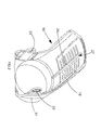
Figure 1 shows a power tool in accordance with an embodiment of the present invention; -
Figure 2 shows a perspective view of an outer casing for a power tool according to an embodiment of the present invention; -
Figure 3 shows a perspective view of a grease supply inlet and a grease cap for a power tool according to an embodiment of the present invention, the grease cap being in an unlocked position; -
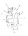
Figure 4 shows a perspective view of the grease cap according to an embodiment of the present invention; -
Figure 5 shows a side view of the grease cap shown inFigure 4 , according to an embodiment of the present invention; -
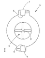
Figure 6 shows a bottom view of the grease cap shown inFigure 4 , according to an embodiment of the present invention; -
Figure 7 shows a perspective view of the grease supply inlet and the grease cap shown inFigure 3 , the grease cap being in a locked position; and -
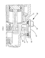
Figures 8 and9 show vertical cross sections of the grease supply inlet and the grease cap shown inFigure 3 in transverse and longitudinal directions, the grease cap being in the locked position. - A grease cap for a power tool in accordance with an embodiment of the present invention will now be described with reference to the accompanying Figures.
- A
power tool 1 according to an aspect of the present invention is represented inFigure 1 . The representedpower tool 1, such as a hammer drill, has a longitudinal axis XX, and anexternal housing 3 which forms agripping portion 5 at its rear end. Aswitch actuator 7 for switching an electric motor (not shown) of thepower tool 1 on and off projects into a grip opening 9. Thegrip opening 9 is defined at its rear end by the grippingportion 5. In the rear lower portion of theexternal housing 3, a mains lead (not shown) is provided to connect thepower tool 1 to a power source. Thepower tool 1 comprises at its front part atool holder 11, in which is inserted a tool (not represented) such as hammer bit, a drill bit or a chisel bit. Thepower tool 1 comprises aninner housing 13, as shown inFigure 3 . The longitudinal axis XX of thepower tool 1 is coincident with a central axis of thetool holder 11. - As shown in
Figure 1 , theexternal housing 3 comprises anouter casing 15 which in the present embodiment is moulded from a plastics material. Theouter casing 15 is shown in more detail inFigure 2 . Theouter casing 15 comprises afront section 17 which is profiled to match the shape of anupper portion 19 of thepower tool 1. Thefront section 17 comprises acircular collar 21 that surrounds the front part of thepower tool 1. Two securingholes 23 are provided on the sides of theouter casing 15 for securing theouter casing 15 to theinternal housing 13. The securing holes 23 align with corresponding holes (not shown) of theinternal housing 13 and a securing bolt, or other mechanical fastener, is located in each securinghole 23 to mount theouter casing 15 to theinternal housing 13. Theouter casing 15 comprises alongitudinal rib 25 extending parallel to the longitudinal axis XX of thepower tool 1. Thelongitudinal rib 25 extends inwardly along an inner surface of thefront section 19, from the rear of thefront section 19 towards thecollar 21. Thelongitudinal rib 25 comprises a lockingregion 27 for locking agrease cap 29 in position, as described herein. - As shown in
Figure 3 , theinternal housing 13 comprises ainlet port 31 for introducing lubricant, for example grease, into theinternal housing 13 to lubricate the crank mechanism of thepower tool 1. Theinlet port 31 is located above the crank mechanism in theinternal housing 13. Theinlet port 31 has a circular shape, and comprises first and secondcircumferential protuberances 33 disposed on its outer edge for securing thecap 29 to theinlet port 31. As shown inFigure 3 , the first andsecond protuberances 33 extend circumferentially on opposite sides of theinlet port 31. First and second diametricallyopposed openings 34 are formed on the outer surface of theinlet port 31 between theprotuberances 33. Furthermore, twostop members 36 are formed on an outer surface of theinlet port 31 to limit rotational movement of thecap 29. A circular seal 35 (for example a deformable O-ring) is disposed inside theinlet port 31, around the internal circumference of theinlet 31. When thecap 29 closes theinlet 31, theseal 35 is disposed between theinlet port 31 and thecap 29, for sealing theinternal housing 13. Thecap 29 is removably mounted to theinlet port 31 and can be removed to facilitate servicing, for example. - The
cap 29 according to an embodiment of the present invention is shown inFigures 4 to 6 . Thecap 29 has a central axis AA and a transverse axis BB (represented inFigure 8 as extending perpendicular to the plane of the page) extending radially outwardly from the central axis AA. Thecap 29 comprises a circulartop portion 37 and astopper portion 39. Thecap 29 also comprises two lockingarms 41 extending downwardly from thetop portion 37. Each lockingarm 41 has aninternal projection 42 projecting radially inwardly towards the central axis AA. When thecap 29 closes theinlet port 31, theprojections 42 of each lockingarm 41 engage an underside of therespective protuberance 33 to prevent thecap 29 being removed, as shown inFigure 7 . The diameter of the circulartop portion 37 is larger than the diameter of theinlet port 31 so as to cover theinlet 31 when thecap 29 is located in theinlet port 31. - The
cap 29 comprises twofinger tabs 43 to allow a user to rotate thecap 29 manually about the central axis AA. Thecap 29 is moulded from a plastics material in the present embodiment, but other materials could be used. Thefinger tabs 43 extend upwardly from thetop portion 37 of thecap 29. Thefinger tabs 43 are arranged in parallel planes and each extends parallel to the transverse axis BB of thecap 29. Specifically, thefinger tabs 43 are offset to opposite sides of the transverse axis BB to form a locking channel 44 (shown inFigure 8 ) therebetween. The lockingchannel 44 has a longitudinal axis which extends diametrically across thetop portion 37 coincident with the transverse axis BB. In alternate arrangements, the longitudinal axis of the lockingchannel 44 could be arranged parallel to and offset from the transverse axis BB. - The
cap 29 is rotatable relative to theinlet port 31 between an unlocked position and a locked position. In the unlocked position, the lockingarms 41 are aligned with theopenings 34 so that thecap 29 can be removed from theinlet port 31. Thecap 29 can be removed to open theinlet port 31, thereby enabling the user to inject grease into the crank mechanism of thepower tool 1. In the locked position, thecap 29 is engaged in theinlet port 31, and the lockingarms 41 are engaged with theprotuberances 33 formed on the outside of theinlet port 31 to prevent thecap 29 being removed. Thecap 29 is rotated into said locked position and the lockingarms 41 abut against thestop members 36 to align thecap 29 such that the lockingchannel 44 extends parallel to the longitudinal axis XX of thepower tool 1. In the locked position, thecap 29 is arranged such that the lockingregion 27 of thelongitudinal rib 25 locates in the lockingchannel 44. The rotation of thecap 29 is thereby inhibited when theouter casing 15 is mounted to theinternal housing 13. Thus, once theouter casing 15 is mounted in position, thecap 29 cannot rotate to its unlocked position. Moreover, theouter casing 15 cannot be mounted if thecap 29 is not in its locked position, thereby preventing assembly of thepower tool 1 if thecap 29 is not properly located in theinlet port 31. - The operation of the
grease cap 29 for apower tool 1 according to an embodiment of the present invention will now be described with reference toFigures 3 and7 to 9 . Initially, thegrease cap 29 is in the unlocked position, as shown inFigure 3 . Theinlet port 31 is thereby open and the user can inject grease in the crank mechanism of thepower tool 1. Once the user has injected the grease, the user locates thegrease cap 29 in theinlet port 31. More precisely, the user disposes thestopper portion 39 into theinlet port 31. The lockingarms 41 extend in theopenings 34 between theprotuberances 33, but do not engage theprotuberances 33. Then, thegrease cap 29 is rotated about the central axis AA out of the unlocked position into the locked position shown inFigures 7 to 9 . Theprojections 42 of the lockingarms 41 are now engaged with an underside of therespective protuberance 33. Thecap 29 is rotated until the lockingarms 41 abut thestop members 36. Thefinger tabs 43 are thereby oriented parallel to the longitudinal axis XX of thepower tool 1. Then, theouter casing 15 is disposed on theupper portion 17 of thepower tool 1 so that the lockingportion 27 of thelongitudinal rib 25 engages the lockingchannel 44 between thefinger tabs 43, and so that the securing holes 23 of theouter casing 15 align with the holes (not shown) of theinner housing 13. Theouter casing 15 is then mounted to theinner housing 13 by introducing bolts into the securing holes of theouter casing 15 and the corresponding holes of theinner housing 13. Theouter casing 15 is thereby mounted to theinner housing 13 such that thelongitudinal rib 25 is located within the lockingchannel 44 formed between thefinger tabs 43 of thegrease cap 29. Thegrease cap 29 is thereby fixed in its locked position such that theinlet port 31 is sealed. - It will be appreciated that various changes and modifications can be made to the grease cap described herein. For example, alternate locking mechanisms could be provided to secure the outer casing with the grease cap. For example, a locking channel could be formed in the outer casing for cooperating with one or more finger tabs provided on the top portion of the grease cap to inhibit rotation of the grease cap. Two parallel longitudinal ribs could be provided on the outer casing to define the locking channel for engaging the one or more finger tabs when the grease cap is in its locked position. The one or more ribs can be arranged in a single plane for locating in the locking channel. A further alternative locking mechanism would be to form a protrusion, such as a longitudinal rib, on the interior of the outer casing to locate in close proximity to a side of said one or more finger tabs to inhibit rotational movement of the grease cap. A still further alternative would be to form one or more recesses in said outer casing for receiving said one or more finger tabs to inhibit rotation of the grease cap.
- A yet further alternative would be to profile a sidewall of the grease cap to cooperate with the outer casing to inhibit rotation of the grease cap. For example, one or more flats could be formed in the sidewall of the grease cap for cooperating with the outer casing.
Claims (22)
- A cap for closing an inlet port for introducing lubricant into a power tool, the power tool having an outer casing, the cap comprising:a top portion,a stopper portion, andat least one engaging member configured to engage the inlet port when the cap is displaced to a locked position;wherein the top portion comprises at least one protrusion for cooperating with the outer casing of the power tool to fix the cap in said locked position.
- A cap as claimed in claim 1, wherein the cap is configured to be rotated to said locked position and the at least one protrusion is arranged to cooperate with the outer casing of the power tool to inhibit rotation of the cap.
- A cap as claimed in claim 1 or claim 2, wherein the at least one protrusion is arranged to cooperate with a locking member provided on an interior of the outer casing.
- A cap as claimed in any one of claims 1, 2 or 3, wherein the top portion comprises first and second protrusions arranged to form a channel for receiving a locking member provided on said outer casing.
- A cap as claimed in claim 4, wherein the first and second protrusions are arranged in parallel planes.
- A cap as claimed in any one of claims 1, 2 or 3, wherein the at least one protrusion is configured to locate in a locking channel defined in the outer casing to fix the cap in said locked position.
- A cap as claimed in anyone of the preceding claims, wherein said at least one engaging member is a locking arm extending from the top portion, the locking arm being arranged so as to abut against a stop member of the inlet port when the cap is in said locked position.
- A cap as claimed in claim 7, wherein the or each locking arm extends parallel to a central axis of the cap.
- A cap as claimed in anyone of the preceding claims, wherein the or each protrusion is a finger tab for allowing a user to rotate the cap manually about the central axis.
- A power tool comprising:an inner housing having an inlet port for introducing lubricant;a cap for closing the inlet port, the cap comprising at least one engaging member configured to engage the inlet port when the cap is displaced to a locked position; andan outer casing for mounting to the inner housing;wherein the cap comprises at least one protrusion for cooperating with the outer casing of the power tool to fix the cap in said locked position.
- A power tool as claimed in claim 10 comprising a longitudinal axis and wherein the locking member is a longitudinal rib extending parallel to the longitudinal axis.
- A power tool as claimed in claim 10 or claim 11, wherein the inlet port is substantially circular and comprises at least one circumferential protuberance; and the cap comprising at least one locking arm for engaging said at least one circumferential protuberance when the cap is in said locked position.
- A power tool as claimed in claim 12, wherein the inlet port comprises at least one stop member, the or each locking arm being arranged so as to abut against the or each stop member when the cap is in said locked position.
- A power tool as claimed in any one of claims 10 to 13, wherein the cap is configured to be rotated into said locked position; and the at least one protrusion cooperates with the outer housing to inhibit rotation of said cap.
- A casing for a power tool, the power tool having an inlet port for introducing lubricant and a cap for closing the inlet port, wherein the casing has at least one locking member for fixing the cap in a locked position to seal the inlet port.
- A casing as claimed in claim 15, wherein the or each locking member is configured to inhibit rotation of the cap when the cap is in said locked position.
- A casing as claimed in claim 15 or claim 16, comprising a longitudinal axis and wherein the or each locking member is a longitudinal rib extending parallel to the longitudinal axis.
- A casing as claimed in any one of claims 15 to 17, wherein the or each locking member is configured to be received in a channel formed on a top portion of the cap when the cap is in said locked position.
- A casing as claimed in any one of claims 15 to 17, comprising a locking channel configured to receive at least one protrusion formed on a top portion of the cap to fix the cap in said locked position.
- A cap substantially as herein described with reference to the accompanying figures.
- A power tool substantially as herein described with reference to the accompanying figures.
- A casing substantially as herein described with reference to the accompanying figures.
Applications Claiming Priority (1)
| Application Number | Priority Date | Filing Date | Title |
|---|---|---|---|
| GBGB1322898.6A GB201322898D0 (en) | 2013-12-23 | 2013-12-23 | Grease cap |
Publications (2)
| Publication Number | Publication Date |
|---|---|
| EP2889109A1 true EP2889109A1 (en) | 2015-07-01 |
| EP2889109B1 EP2889109B1 (en) | 2017-06-14 |
Family
ID=50114663
Family Applications (1)
| Application Number | Title | Priority Date | Filing Date |
|---|---|---|---|
| EP14192718.6A Active EP2889109B1 (en) | 2013-12-23 | 2014-11-11 | Grease cap |
Country Status (2)
| Country | Link |
|---|---|
| EP (1) | EP2889109B1 (en) |
| GB (1) | GB201322898D0 (en) |
Citations (5)
| Publication number | Priority date | Publication date | Assignee | Title |
|---|---|---|---|---|
| US2897919A (en) * | 1957-03-21 | 1959-08-04 | Westinghouse Air Brake Co | Airline oiler |
| EP0133520A2 (en) * | 1983-08-11 | 1985-02-27 | Jacob Berg GmbH & Co. KG | Container closure with venting means |
| US6123212A (en) * | 1999-08-27 | 2000-09-26 | Alcoa Closure Systems International | Plastic closure with rotation-inhibiting projections |
| EP2281662A2 (en) * | 2009-08-05 | 2011-02-09 | Makita Corporation | Power tool |
| EP2433755A1 (en) * | 2009-05-20 | 2012-03-28 | Makita Corporation | Powered tool |
-
2013
- 2013-12-23 GB GBGB1322898.6A patent/GB201322898D0/en not_active Ceased
-
2014
- 2014-11-11 EP EP14192718.6A patent/EP2889109B1/en active Active
Patent Citations (5)
| Publication number | Priority date | Publication date | Assignee | Title |
|---|---|---|---|---|
| US2897919A (en) * | 1957-03-21 | 1959-08-04 | Westinghouse Air Brake Co | Airline oiler |
| EP0133520A2 (en) * | 1983-08-11 | 1985-02-27 | Jacob Berg GmbH & Co. KG | Container closure with venting means |
| US6123212A (en) * | 1999-08-27 | 2000-09-26 | Alcoa Closure Systems International | Plastic closure with rotation-inhibiting projections |
| EP2433755A1 (en) * | 2009-05-20 | 2012-03-28 | Makita Corporation | Powered tool |
| EP2281662A2 (en) * | 2009-08-05 | 2011-02-09 | Makita Corporation | Power tool |
Also Published As
| Publication number | Publication date |
|---|---|
| EP2889109B1 (en) | 2017-06-14 |
| GB201322898D0 (en) | 2014-02-12 |
Similar Documents
| Publication | Publication Date | Title |
|---|---|---|
| EP3179148B1 (en) | Lock mechanism for tubular body | |
| US20150272394A1 (en) | Blender | |
| CN101563190B (en) | Electric device with locked-on rotatable operating element | |
| US10773369B2 (en) | Fastener retention device for a guard cover | |
| JP5767019B2 (en) | Bumper retainer | |
| KR20170072449A (en) | Automatic opening and shutting structure for electric heating cooker | |
| JP2012087778A (en) | Receptacle for fluid, in particular engine oil pan or transmission oil pan for motor vehcle | |
| CA2758552A1 (en) | Needle valve | |
| US10723223B2 (en) | Fuel cap | |
| JP2015177735A (en) | Insert casing for fixing electric component, object fixing insert casing, and fixing method for fixing insert casing to object | |
| US20090074535A1 (en) | Fastener assembly | |
| US20140014660A1 (en) | Fuel inlet device with a cap member for a fuel tank | |
| EP2889109B1 (en) | Grease cap | |
| CN110886757A (en) | Anti-vibration quick-release lock | |
| JP2009500570A (en) | Filter lip seal and method | |
| US9016499B2 (en) | Adapter for an oil filler neck and assembly method for the adapter | |
| US10258908B2 (en) | Filter module with window type clear bowl | |
| CN110393437B (en) | cooking utensils | |
| CN203750283U (en) | Filter bottle of water purification equipment and water purification equipment having same | |
| US6800975B2 (en) | Electric motor shaft access cover | |
| KR200466742Y1 (en) | Gear box body for anti panic assembly | |
| CN220477387U (en) | Cup | |
| WO2019110145A1 (en) | Explosion-protected housing | |
| CN219318780U (en) | Drain pipe assembly for refrigerator and refrigerator | |
| KR910008061Y1 (en) | Gas valve shutoff device |
Legal Events
| Date | Code | Title | Description |
|---|---|---|---|
| PUAI | Public reference made under article 153(3) epc to a published international application that has entered the european phase |
Free format text: ORIGINAL CODE: 0009012 |
|
| 17P | Request for examination filed |
Effective date: 20141111 |
|
| AK | Designated contracting states |
Kind code of ref document: A1 Designated state(s): AL AT BE BG CH CY CZ DE DK EE ES FI FR GB GR HR HU IE IS IT LI LT LU LV MC MK MT NL NO PL PT RO RS SE SI SK SM TR |
|
| AX | Request for extension of the european patent |
Extension state: BA ME |
|
| R17P | Request for examination filed (corrected) |
Effective date: 20150727 |
|
| RBV | Designated contracting states (corrected) |
Designated state(s): AL AT BE BG CH CY CZ DE DK EE ES FI FR GB GR HR HU IE IS IT LI LT LU LV MC MK MT NL NO PL PT RO RS SE SI SK SM TR |
|
| GRAP | Despatch of communication of intention to grant a patent |
Free format text: ORIGINAL CODE: EPIDOSNIGR1 |
|
| STAA | Information on the status of an ep patent application or granted ep patent |
Free format text: STATUS: GRANT OF PATENT IS INTENDED |
|
| GRAS | Grant fee paid |
Free format text: ORIGINAL CODE: EPIDOSNIGR3 |
|
| GRAA | (expected) grant |
Free format text: ORIGINAL CODE: 0009210 |
|
| STAA | Information on the status of an ep patent application or granted ep patent |
Free format text: STATUS: THE PATENT HAS BEEN GRANTED |
|
| INTG | Intention to grant announced |
Effective date: 20170419 |
|
| RIN1 | Information on inventor provided before grant (corrected) |
Inventor name: ROBERTS, ANA-MARIE |
|
| AK | Designated contracting states |
Kind code of ref document: B1 Designated state(s): AL AT BE BG CH CY CZ DE DK EE ES FI FR GB GR HR HU IE IS IT LI LT LU LV MC MK MT NL NO PL PT RO RS SE SI SK SM TR |
|
| REG | Reference to a national code |
Ref country code: GB Ref legal event code: FG4D |
|
| REG | Reference to a national code |
Ref country code: CH Ref legal event code: EP Ref country code: AT Ref legal event code: REF Ref document number: 900513 Country of ref document: AT Kind code of ref document: T Effective date: 20170615 |
|
| REG | Reference to a national code |
Ref country code: IE Ref legal event code: FG4D |
|
| REG | Reference to a national code |
Ref country code: DE Ref legal event code: R096 Ref document number: 602014010712 Country of ref document: DE |
|
| REG | Reference to a national code |
Ref country code: NL Ref legal event code: MP Effective date: 20170614 |
|
| REG | Reference to a national code |
Ref country code: LT Ref legal event code: MG4D |
|
| PG25 | Lapsed in a contracting state [announced via postgrant information from national office to epo] |
Ref country code: FI Free format text: LAPSE BECAUSE OF FAILURE TO SUBMIT A TRANSLATION OF THE DESCRIPTION OR TO PAY THE FEE WITHIN THE PRESCRIBED TIME-LIMIT Effective date: 20170614 Ref country code: HR Free format text: LAPSE BECAUSE OF FAILURE TO SUBMIT A TRANSLATION OF THE DESCRIPTION OR TO PAY THE FEE WITHIN THE PRESCRIBED TIME-LIMIT Effective date: 20170614 Ref country code: LT Free format text: LAPSE BECAUSE OF FAILURE TO SUBMIT A TRANSLATION OF THE DESCRIPTION OR TO PAY THE FEE WITHIN THE PRESCRIBED TIME-LIMIT Effective date: 20170614 Ref country code: GR Free format text: LAPSE BECAUSE OF FAILURE TO SUBMIT A TRANSLATION OF THE DESCRIPTION OR TO PAY THE FEE WITHIN THE PRESCRIBED TIME-LIMIT Effective date: 20170915 Ref country code: NO Free format text: LAPSE BECAUSE OF FAILURE TO SUBMIT A TRANSLATION OF THE DESCRIPTION OR TO PAY THE FEE WITHIN THE PRESCRIBED TIME-LIMIT Effective date: 20170914 |
|
| REG | Reference to a national code |
Ref country code: AT Ref legal event code: MK05 Ref document number: 900513 Country of ref document: AT Kind code of ref document: T Effective date: 20170614 |
|
| PG25 | Lapsed in a contracting state [announced via postgrant information from national office to epo] |
Ref country code: LV Free format text: LAPSE BECAUSE OF FAILURE TO SUBMIT A TRANSLATION OF THE DESCRIPTION OR TO PAY THE FEE WITHIN THE PRESCRIBED TIME-LIMIT Effective date: 20170614 Ref country code: NL Free format text: LAPSE BECAUSE OF FAILURE TO SUBMIT A TRANSLATION OF THE DESCRIPTION OR TO PAY THE FEE WITHIN THE PRESCRIBED TIME-LIMIT Effective date: 20170614 Ref country code: BG Free format text: LAPSE BECAUSE OF FAILURE TO SUBMIT A TRANSLATION OF THE DESCRIPTION OR TO PAY THE FEE WITHIN THE PRESCRIBED TIME-LIMIT Effective date: 20170914 Ref country code: SE Free format text: LAPSE BECAUSE OF FAILURE TO SUBMIT A TRANSLATION OF THE DESCRIPTION OR TO PAY THE FEE WITHIN THE PRESCRIBED TIME-LIMIT Effective date: 20170614 Ref country code: RS Free format text: LAPSE BECAUSE OF FAILURE TO SUBMIT A TRANSLATION OF THE DESCRIPTION OR TO PAY THE FEE WITHIN THE PRESCRIBED TIME-LIMIT Effective date: 20170614 |
|
| PG25 | Lapsed in a contracting state [announced via postgrant information from national office to epo] |
Ref country code: SK Free format text: LAPSE BECAUSE OF FAILURE TO SUBMIT A TRANSLATION OF THE DESCRIPTION OR TO PAY THE FEE WITHIN THE PRESCRIBED TIME-LIMIT Effective date: 20170614 Ref country code: AT Free format text: LAPSE BECAUSE OF FAILURE TO SUBMIT A TRANSLATION OF THE DESCRIPTION OR TO PAY THE FEE WITHIN THE PRESCRIBED TIME-LIMIT Effective date: 20170614 Ref country code: EE Free format text: LAPSE BECAUSE OF FAILURE TO SUBMIT A TRANSLATION OF THE DESCRIPTION OR TO PAY THE FEE WITHIN THE PRESCRIBED TIME-LIMIT Effective date: 20170614 Ref country code: CZ Free format text: LAPSE BECAUSE OF FAILURE TO SUBMIT A TRANSLATION OF THE DESCRIPTION OR TO PAY THE FEE WITHIN THE PRESCRIBED TIME-LIMIT Effective date: 20170614 Ref country code: RO Free format text: LAPSE BECAUSE OF FAILURE TO SUBMIT A TRANSLATION OF THE DESCRIPTION OR TO PAY THE FEE WITHIN THE PRESCRIBED TIME-LIMIT Effective date: 20170614 |
|
| PG25 | Lapsed in a contracting state [announced via postgrant information from national office to epo] |
Ref country code: IS Free format text: LAPSE BECAUSE OF FAILURE TO SUBMIT A TRANSLATION OF THE DESCRIPTION OR TO PAY THE FEE WITHIN THE PRESCRIBED TIME-LIMIT Effective date: 20171014 Ref country code: PL Free format text: LAPSE BECAUSE OF FAILURE TO SUBMIT A TRANSLATION OF THE DESCRIPTION OR TO PAY THE FEE WITHIN THE PRESCRIBED TIME-LIMIT Effective date: 20170614 Ref country code: IT Free format text: LAPSE BECAUSE OF FAILURE TO SUBMIT A TRANSLATION OF THE DESCRIPTION OR TO PAY THE FEE WITHIN THE PRESCRIBED TIME-LIMIT Effective date: 20170614 Ref country code: ES Free format text: LAPSE BECAUSE OF FAILURE TO SUBMIT A TRANSLATION OF THE DESCRIPTION OR TO PAY THE FEE WITHIN THE PRESCRIBED TIME-LIMIT Effective date: 20170614 Ref country code: SM Free format text: LAPSE BECAUSE OF FAILURE TO SUBMIT A TRANSLATION OF THE DESCRIPTION OR TO PAY THE FEE WITHIN THE PRESCRIBED TIME-LIMIT Effective date: 20170614 |
|
| REG | Reference to a national code |
Ref country code: DE Ref legal event code: R097 Ref document number: 602014010712 Country of ref document: DE |
|
| PLBE | No opposition filed within time limit |
Free format text: ORIGINAL CODE: 0009261 |
|
| STAA | Information on the status of an ep patent application or granted ep patent |
Free format text: STATUS: NO OPPOSITION FILED WITHIN TIME LIMIT |
|
| PG25 | Lapsed in a contracting state [announced via postgrant information from national office to epo] |
Ref country code: DK Free format text: LAPSE BECAUSE OF FAILURE TO SUBMIT A TRANSLATION OF THE DESCRIPTION OR TO PAY THE FEE WITHIN THE PRESCRIBED TIME-LIMIT Effective date: 20170614 |
|
| 26N | No opposition filed |
Effective date: 20180315 |
|
| PG25 | Lapsed in a contracting state [announced via postgrant information from national office to epo] |
Ref country code: MC Free format text: LAPSE BECAUSE OF FAILURE TO SUBMIT A TRANSLATION OF THE DESCRIPTION OR TO PAY THE FEE WITHIN THE PRESCRIBED TIME-LIMIT Effective date: 20170614 |
|
| PG25 | Lapsed in a contracting state [announced via postgrant information from national office to epo] |
Ref country code: CH Free format text: LAPSE BECAUSE OF NON-PAYMENT OF DUE FEES Effective date: 20171130 Ref country code: LI Free format text: LAPSE BECAUSE OF NON-PAYMENT OF DUE FEES Effective date: 20171130 |
|
| PG25 | Lapsed in a contracting state [announced via postgrant information from national office to epo] |
Ref country code: LU Free format text: LAPSE BECAUSE OF NON-PAYMENT OF DUE FEES Effective date: 20171111 Ref country code: SI Free format text: LAPSE BECAUSE OF FAILURE TO SUBMIT A TRANSLATION OF THE DESCRIPTION OR TO PAY THE FEE WITHIN THE PRESCRIBED TIME-LIMIT Effective date: 20170614 |
|
| REG | Reference to a national code |
Ref country code: FR Ref legal event code: ST Effective date: 20180731 Ref country code: BE Ref legal event code: MM Effective date: 20171130 |
|
| REG | Reference to a national code |
Ref country code: IE Ref legal event code: MM4A |
|
| PG25 | Lapsed in a contracting state [announced via postgrant information from national office to epo] |
Ref country code: MT Free format text: LAPSE BECAUSE OF NON-PAYMENT OF DUE FEES Effective date: 20171111 |
|
| PG25 | Lapsed in a contracting state [announced via postgrant information from national office to epo] |
Ref country code: IE Free format text: LAPSE BECAUSE OF NON-PAYMENT OF DUE FEES Effective date: 20171111 Ref country code: FR Free format text: LAPSE BECAUSE OF NON-PAYMENT OF DUE FEES Effective date: 20171130 |
|
| PG25 | Lapsed in a contracting state [announced via postgrant information from national office to epo] |
Ref country code: BE Free format text: LAPSE BECAUSE OF NON-PAYMENT OF DUE FEES Effective date: 20171130 |
|
| PG25 | Lapsed in a contracting state [announced via postgrant information from national office to epo] |
Ref country code: HU Free format text: LAPSE BECAUSE OF FAILURE TO SUBMIT A TRANSLATION OF THE DESCRIPTION OR TO PAY THE FEE WITHIN THE PRESCRIBED TIME-LIMIT; INVALID AB INITIO Effective date: 20141111 |
|
| PG25 | Lapsed in a contracting state [announced via postgrant information from national office to epo] |
Ref country code: CY Free format text: LAPSE BECAUSE OF FAILURE TO SUBMIT A TRANSLATION OF THE DESCRIPTION OR TO PAY THE FEE WITHIN THE PRESCRIBED TIME-LIMIT Effective date: 20170614 |
|
| PG25 | Lapsed in a contracting state [announced via postgrant information from national office to epo] |
Ref country code: MK Free format text: LAPSE BECAUSE OF FAILURE TO SUBMIT A TRANSLATION OF THE DESCRIPTION OR TO PAY THE FEE WITHIN THE PRESCRIBED TIME-LIMIT Effective date: 20170614 |
|
| PG25 | Lapsed in a contracting state [announced via postgrant information from national office to epo] |
Ref country code: TR Free format text: LAPSE BECAUSE OF FAILURE TO SUBMIT A TRANSLATION OF THE DESCRIPTION OR TO PAY THE FEE WITHIN THE PRESCRIBED TIME-LIMIT Effective date: 20170614 |
|
| PG25 | Lapsed in a contracting state [announced via postgrant information from national office to epo] |
Ref country code: PT Free format text: LAPSE BECAUSE OF FAILURE TO SUBMIT A TRANSLATION OF THE DESCRIPTION OR TO PAY THE FEE WITHIN THE PRESCRIBED TIME-LIMIT Effective date: 20170614 |
|
| PG25 | Lapsed in a contracting state [announced via postgrant information from national office to epo] |
Ref country code: AL Free format text: LAPSE BECAUSE OF FAILURE TO SUBMIT A TRANSLATION OF THE DESCRIPTION OR TO PAY THE FEE WITHIN THE PRESCRIBED TIME-LIMIT Effective date: 20170614 |
|
| PGFP | Annual fee paid to national office [announced via postgrant information from national office to epo] |
Ref country code: DE Payment date: 20251118 Year of fee payment: 12 |
|
| PGFP | Annual fee paid to national office [announced via postgrant information from national office to epo] |
Ref country code: GB Payment date: 20251120 Year of fee payment: 12 |