EP2889108A2 - Belt holder - Google Patents
Belt holder Download PDFInfo
- Publication number
- EP2889108A2 EP2889108A2 EP14004304.3A EP14004304A EP2889108A2 EP 2889108 A2 EP2889108 A2 EP 2889108A2 EP 14004304 A EP14004304 A EP 14004304A EP 2889108 A2 EP2889108 A2 EP 2889108A2
- Authority
- EP
- European Patent Office
- Prior art keywords
- buckle closure
- closure body
- hook
- held
- hand
- Prior art date
- Legal status (The legal status is an assumption and is not a legal conclusion. Google has not performed a legal analysis and makes no representation as to the accuracy of the status listed.)
- Granted
Links
- 238000007373 indentation Methods 0.000 claims abstract description 8
- 229910000639 Spring steel Inorganic materials 0.000 claims description 6
- 238000005452 bending Methods 0.000 claims description 4
- 238000005096 rolling process Methods 0.000 claims description 4
- 238000004519 manufacturing process Methods 0.000 description 3
- 230000037431 insertion Effects 0.000 description 2
- 238000003780 insertion Methods 0.000 description 2
- 150000001875 compounds Chemical class 0.000 description 1
- 230000000881 depressing effect Effects 0.000 description 1
- 230000000694 effects Effects 0.000 description 1
Images

Classifications
-
- A—HUMAN NECESSITIES
- A45—HAND OR TRAVELLING ARTICLES
- A45F—TRAVELLING OR CAMP EQUIPMENT: SACKS OR PACKS CARRIED ON THE BODY
- A45F5/00—Holders or carriers for hand articles; Holders or carriers for use while travelling or camping
- A45F5/02—Fastening articles to the garment
- A45F5/021—Fastening articles to the garment to the belt
-
- B—PERFORMING OPERATIONS; TRANSPORTING
- B25—HAND TOOLS; PORTABLE POWER-DRIVEN TOOLS; MANIPULATORS
- B25F—COMBINATION OR MULTI-PURPOSE TOOLS NOT OTHERWISE PROVIDED FOR; DETAILS OR COMPONENTS OF PORTABLE POWER-DRIVEN TOOLS NOT PARTICULARLY RELATED TO THE OPERATIONS PERFORMED AND NOT OTHERWISE PROVIDED FOR
- B25F5/00—Details or components of portable power-driven tools not particularly related to the operations performed and not otherwise provided for
- B25F5/02—Construction of casings, bodies or handles
Definitions
- the present utility model relates to the technical field of a buckle closure, in particular a removable Gurtschnallenver gleich for hand-held, electrically powered tool.
- the technical problem to be solved by the present invention is to provide a more removable buckle closure for hand-held, electrically driven tool which supports the buckled at the waist entrainment of the hand-held, electrically powered tool on the left or right side allows.
- the present utility model provides the following technical concept for a more removable buckle closure for hand-held, electrically powered tool:
- a buckle closure base and a buckle closure body wherein the buckle closure base is for connection to the belt while the buckle closure body is for connection to the electrically powered tool; wherein the buckle closure body is tuned to the provided on both sides of the housing end of the electrically driven tool clamping grooves; wherein on the buckle closure body, a hook-shaped tongue is formed; wherein at least one indentation groove of the buckle closure body is provided on the buckle closure body; wherein the hook-shaped tongue and the recessed groove of the buckle closure body are tuned to the clamping grooves provided on both sides of the housing end of the electrically driven tool.
- the attachment end of the above-mentioned hook-shaped tongue is fixedly connected to the buckle closure body, wherein between the hook-shaped tongue and the buckle closure body, an angle of 6-8 degrees is formed.
- the free end of the above-mentioned hook-shaped tongue forms a curved surface.
- the above-mentioned indentation grooves of the buckle closure body are triangular in shape.
- the belt buckle closure described above is made by rolling and bending stainless spring steel.
- the present utility model allows the waist-belted entrainment of the hand-held, electrically driven tool on the left or right side, whereby the rapid decrease is possible without requiring further tools.
- the present utility model is manufactured by rolling and bending stainless spring steel, durable use, simple manufacturing and operation, has low production cost and easy practicality, and is suitable for mass production.
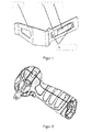
- FIG. 1 it is the representation of the removable buckle closure for hand-held, electrically powered tool according to the present utility model.
- the present utility model is a detachable buckle closure for a hand-held power tool having a buckle closure base 1 and a buckle closure body 2 as a whole, the buckle closure base 1 being for connection to the belt while the buckle closure body 2 is for connection used with the electrically driven tool; wherein the buckle closure body 2 is tuned to the provided on both sides of the housing end of the electrically driven tool clamping grooves;
- a hook-shaped tongue 3 is formed; wherein on the buckle closure body 2, two triangular Indentation grooves 4 are provided; wherein the attachment end of the hook-shaped tongue 3 is fixedly connected to the buckle closure body 2, wherein between the hook-shaped tongue 3 and the buckle closure body 2, an angle of 6-8 degrees is formed, wherein the free end of the hook-shaped tongue 3 forms a curved surface and wherein the hook-shaped tongue 3 and the triangular Einbuchtungsrillen 4 are tuned to the provided on both sides of the housing end of the electrically driven tool clamping grooves.
- the hook-shaped tongue 3 of the buckle closure body 2 is bordered at will in the left side or right side of the housing of the electrically driven tool, so that then by the buckle base 1, the electrically driven tool at will at any position on Strap of the user can be hung and where by depressing the hook-shaped tongue 3 of the buckle closure can be easily removed.
- the present utility model can be framed on the left side or the right side of the power tool so that the user can freely hang on the left or right side waist according to his habits of left or right hand use the acceptance is flexible and the use is convenient and an efficient solution to a number of problems is encountered in the entrainment of hand-held, electrically powered tools.
- the present utility model is manufactured by rolling and bending of stainless spring steel, wherein the elasticity of the spring steel realizes the locking of the belt.
- the present utility model can be used extensively for various hand-held, electrically driven tools.
Abstract
Das vorliegende Gebrauchsmuster offenbart einen abnehmbaren Gurtschnallenverschluss für handgehaltenes, elektrisch angetriebenes Werkzeug, welcher als Ganzes ausgebildet eine Schnallenverschlussbasis und einen Schnallenverschlusskörper umfasst, wobei die Schnallenverschlussbasis der Verbindung mit dem Gurt dient, während der Schnallenverschlusskörper der Verbindung mit dem elektrisch angetriebenen Werkzeug dient; wobei der Schnallenverschlusskörper auf die an beiden Seiten des Gehäuseendes des elektrisch angetriebenen Werkzeugs vorgesehenen Klemmrillen abgestimmt ist; wobei an dem Schnallenverschlusskörper eine hakenförmigen Zunge ausgebildet ist; wobei an dem Schnallenverschlusskörper zumindest eine Einbuchtungsrille des Schnallenverschlusskörpers vorgesehen ist; wobei die hakenförmige Zunge und die Einbuchtungsrille des Schnallenverschlusskörpers auf die an beiden Seiten des Gehäuseendes des elektrisch angetriebenen Werkzeugs vorgesehenen Klemmrillen abgestimmt sind. Das vorliegende Gebrauchsmuster ermöglicht die an der Taille hängend angeschnallte Mitführung des handgehaltenen, elektrisch angetriebenen Werkzeugs an der linken oder rechten Seite, wobei ohne Erfordernis weiterer Werkzeuge die schnelle Abnahme möglich ist.The present utility model discloses a detachable buckle fastener for hand-held electrically powered tool which as a whole comprises a buckle closure base and a buckle closure body, the buckle closure base serving to connect to the strap while the buckle closure body is for connection to the electrically powered tool; wherein the buckle closure body is tuned to the provided on both sides of the housing end of the electrically driven tool clamping grooves; wherein on the buckle closure body, a hook-shaped tongue is formed; wherein at least one indentation groove of the buckle closure body is provided on the buckle closure body; wherein the hook-shaped tongue and the recessed groove of the buckle closure body are tuned to the clamping grooves provided on both sides of the housing end of the electrically driven tool. The present utility model allows the waist-belted entrainment of the hand-held, electrically driven tool on the left or right side, whereby the rapid decrease is possible without requiring further tools.
Description
Das vorliegende Gebrauchsmuster betrifft das technische Gebiet eines Gurtschnallenverschlusses, insbesondere einen abnehmbarerem Gurtschnallenverschluss für handgehaltenes, elektrisch angetriebenes Werkzeug.The present utility model relates to the technical field of a buckle closure, in particular a removable Gurtschnallenverschluss for hand-held, electrically powered tool.
Gegenwärtig vorhandene handgehaltene, elektrisch angetriebene Werkzeuge weisen normalerweise eine Mitführvorrichtung als Zubehör auf, wobei die elektrisch angetriebenen Werkzeuge mit als Zubehör vorgesehener Mitführvorrichtung meistens mittels zusätzlichem Werkzeug an dem Ende des Griffes des elektrisch angetriebenen Werkzeugs befestigt werden. Daher bedarf es zusätzlichen Werkzeugs, um das elektrisch angetriebene Werkzeug am Körper mitführen zu können. Weil die Abnahme des zusätzlichen Werkzeugs allerdings sehr umständlich ist erfolgt eine enorme Beeinträchtigung der Mitführbarkeit des elektrisch angetriebenen Werkzeugs, was zu einer Erschwernis der Verwendung durch den Benutzer führt.Presently available hand-held, electrically driven tools usually have a carry-along accessory, wherein the electrically driven tools are attached with accessories provided entrainment usually by means of additional tools to the end of the handle of the electrically driven tool. Therefore, it requires additional tools to carry the electrically powered tool on the body can. However, because the removal of the additional tool is very cumbersome, there is a tremendous impact on the maneuverability of the electrically driven tool, which leads to complication of use by the user.
Das durch das vorliegende Gebrauchsmuster zu lösende technische Problem besteht in der Bereitstellung eines abnehmbareren Gurtschnallenverschlusses für handgehaltenes, elektrisch angetriebenes Werkzeug, welcher die an der Taille hängend angeschnallte Mitführung des handgehaltenen, elektrisch angetriebenen Werkzeugs an der linken oder rechten Seite ermöglicht.The technical problem to be solved by the present invention is to provide a more removable buckle closure for hand-held, electrically driven tool which supports the buckled at the waist entrainment of the hand-held, electrically powered tool on the left or right side allows.
Zwecks Lösung des vorstehend bezeichneten technischen Problems sieht das vorliegende Gebrauchsmuster die nachstehend aufgeführte technische Konzeption für einen abnehmbareren Gurtschnallenverschluss für handgehaltenes, elektrisch angetriebenes Werkzeug vor:In order to solve the technical problem described above, the present utility model provides the following technical concept for a more removable buckle closure for hand-held, electrically powered tool:
Dieser umfasst als Ganzes ausgebildet eine Schnallenverschlussbasis und einen Schnallenverschlusskörper, wobei die Schnallenverschlussbasis der Verbindung mit dem Gurt dient, während der Schnallenverschlusskörper der Verbindung mit dem elektrisch angetriebenen Werkzeug dient; wobei der Schnallenverschlusskörper auf die an beiden Seiten des Gehäuseendes des elektrisch angetriebenen Werkzeugs vorgesehenen Klemmrillen abgestimmt ist; wobei an dem Schnallenverschlusskörper eine hakenförmigen Zunge ausgebildet ist; wobei an dem Schnallenverschlusskörper zumindest eine Einbuchtungsrille des Schnallenverschlusskörpers vorgesehen ist; wobei die hakenförmige Zunge und die Einbuchtungsrille des Schnallenverschlusskörpers auf die an beiden Seiten des Gehäuseendes des elektrisch angetriebenen Werkzeugs vorgesehenen Klemmrillen abgestimmt sind.This comprises, as a whole, a buckle closure base and a buckle closure body, wherein the buckle closure base is for connection to the belt while the buckle closure body is for connection to the electrically powered tool; wherein the buckle closure body is tuned to the provided on both sides of the housing end of the electrically driven tool clamping grooves; wherein on the buckle closure body, a hook-shaped tongue is formed; wherein at least one indentation groove of the buckle closure body is provided on the buckle closure body; wherein the hook-shaped tongue and the recessed groove of the buckle closure body are tuned to the clamping grooves provided on both sides of the housing end of the electrically driven tool.
Das Befestigungsende der vorstehend bezeichneten hakenförmigen Zunge ist an dem Schnallenverschlusskörper fest verbunden, wobei zwischen der hakenförmigen Zunge und dem Schnallenverschlusskörper ein Winkel von 6-8 Grad gebildet wird.The attachment end of the above-mentioned hook-shaped tongue is fixedly connected to the buckle closure body, wherein between the hook-shaped tongue and the buckle closure body, an angle of 6-8 degrees is formed.
Das freie Ende der vorstehend bezeichneten hakenförmigen Zunge bildet eine gebogene Fläche.The free end of the above-mentioned hook-shaped tongue forms a curved surface.
Die vorstehend bezeichneten Einbuchtungsrillen des Schnallenverschlusskörpers sind von dreieckiger Form.The above-mentioned indentation grooves of the buckle closure body are triangular in shape.
Der vorstehend bezeichnete Gurtschnallenverschluss ist durch Walzen und Biegen aus rostfreiem Federstahl hergestellt.The belt buckle closure described above is made by rolling and bending stainless spring steel.
Das vorliegende Gebrauchsmuster kann die nachstehend aufgeführten technischen Effekte darstellen:The present utility model can represent the following technical effects:
Das vorliegende Gebrauchsmuster ermöglicht die an der Taille hängend angeschnallte Mitführung des handgehaltenen, elektrisch angetriebenen Werkzeugs an der linken oder rechten Seite, wobei ohne Erfordernis weiterer Werkzeuge die schnelle Abnahme möglich ist.The present utility model allows the waist-belted entrainment of the hand-held, electrically driven tool on the left or right side, whereby the rapid decrease is possible without requiring further tools.
Das vorliegenden Gebrauchsmuster ist durch Walzen und Biegen aus rostfreiem Federstahl hergestellt, dauerhaft verwendungsbeständig, von einfacher Herstellung und Bedienung, weist niedrige Produktionskosten und einfacher Praktikabilität auf und ist für eine Massenproduktion geeignet.The present utility model is manufactured by rolling and bending stainless spring steel, durable use, simple manufacturing and operation, has low production cost and easy practicality, and is suitable for mass production.
Nachstehend aufgeführt erfolgt anhand der beigefügten Abbildungen sowie anhand praktischer Ausführungsbeispiele eine weitere detaillierte Erläuterung des vorliegenden Gebrauchsmusters:The following is a more detailed explanation of the present utility model with reference to the accompanying drawings and practical examples:
Bei
Bei
Bei
Erläuterung der Bezugszeichen in den Abbildungen:
- 1 Schnallenverschlussbasis
- 2 Schnallenverschlusskörper
- 3 Hakenförmige Zunge
- 4 Dreieckige Einbuchtungsrille
- 1 buckle base
- 2 buckle closure body
- 3 Hook-shaped tongue
- 4 Triangular indentation groove
Wie in
wobei an dem Schnallenverschlusskörper 2 eine hakenförmigen Zunge 3 ausgebildet ist; wobei an dem Schnallenverschlusskörper 2 zwei dreieckige Einbuchtungsrillen 4 vorgesehen sind; wobei das Befestigungsende der hakenförmigen Zunge 3 an dem Schnallenverschlusskörper 2 fest verbunden ist, wobei zwischen der hakenförmigen Zunge 3 und dem Schnallenverschlusskörper 2 ein Winkel von 6-8 Grad gebildet wird, wobei das freie Ende der hakenförmigen Zunge 3 eine gebogene Fläche bildet und wobei die hakenförmige Zunge 3 und die dreieckigen Einbuchtungsrillen 4 auf die an beiden Seiten des Gehäuseendes des elektrisch angetriebenen Werkzeugs vorgesehenen Klemmrillen abgestimmt sind.wherein on the
Wie in
Bei der Verwendung wird entsprechend den Verwendungsgewohnheiten des Benutzers die hakenförmige Zunge 3 des Schnallenverschlusskörpers 2 nach Belieben in die linke Seite oder rechte Seite am Gehäuse des elektrisch angetriebenen Werkzeugs eingefasst, so dass anschließend durch die Schnallenverschlussbasis 1 das elektrisch angetriebene Werkzeug nach Belieben an beliebiger Position am Gurt des Benutzers aufgehängt werden kann und wobei durch Niederdrücken der hakenförmigen Zunge 3 der Gurtschnallenverschluss bequem abgenommen werden kann.In use, according to the usage habits of the user, the hook-shaped tongue 3 of the
Das vorliegende Gebrauchsmuster kann an der linken Seite oder der rechten Seite des elektrisch angetriebenen Werkzeugs eingefasst werden, so dass dem Benutzer gemäß seinen Gewohnheiten bezüglich der Verwendung mit der linken oder rechten Hand nach Belieben die hängende Mitführung an der Taille an der linken oder rechten Seite erleichtert wird, wobei die Abnahme flexibel und die Verwendung bequem ist und wobei eine effiziente Lösung einer Reihe von Problemen bei der Mitführung von handgehaltenen, elektrisch angetriebenen Werkzeugen erfolgt.The present utility model can be framed on the left side or the right side of the power tool so that the user can freely hang on the left or right side waist according to his habits of left or right hand use the acceptance is flexible and the use is convenient and an efficient solution to a number of problems is encountered in the entrainment of hand-held, electrically powered tools.
Das vorliegende Gebrauchsmuster ist durch Walzen und Biegen aus rostfreiem Federstahl hergestellt, wobei die Elastizität des Federstahls die Verriegelung des Gurtes verwirklicht.The present utility model is manufactured by rolling and bending of stainless spring steel, wherein the elasticity of the spring steel realizes the locking of the belt.
Das vorliegende Gebrauchsmuster kann umfassend für verschiedene handgehaltene, elektrisch angetriebene Werkzeuge verwendet werden.The present utility model can be used extensively for various hand-held, electrically driven tools.
Claims (5)
wobei an dem Schnallenverschlusskörper eine hakenförmigen Zunge ausgebildet ist; wobei an dem Schnallenverschlusskörper zumindest eine Einbuchtungsrille des Schnallenverschlusskörpers vorgesehen ist; wobei die hakenförmige Zunge und die Einbuchtungsrille des Schnallenverschlusskörpers auf die an beiden Seiten des Gehäuseendes des elektrisch angetriebenen Werkzeugs vorgesehenen Klemmrillen abgestimmt sind.A detachable buckle closure for hand-held, electrically powered tool, characterized in that it comprises a buckle fastening base and a buckle closure body as a whole, the buckle closure base serving to connect to the strap while the buckle closure body is for connection to the electrically powered tool; wherein the buckle closure body is tuned to the provided on both sides of the housing end of the electrically driven tool clamping grooves;
wherein on the buckle closure body, a hook-shaped tongue is formed; wherein at least one indentation groove of the buckle closure body is provided on the buckle closure body; wherein the hook-shaped tongue and the recessed groove of the buckle closure body are tuned to the clamping grooves provided on both sides of the housing end of the electrically driven tool.
Applications Claiming Priority (1)
| Application Number | Priority Date | Filing Date | Title |
|---|---|---|---|
| CN201320842733.0U CN203662125U (en) | 2013-12-19 | 2013-12-19 | Detachable belt fastener used for handheld electric tool |
Related Parent Applications (1)
| Application Number | Title | Priority Date | Filing Date |
|---|---|---|---|
| CN201320842733U Previously-Filed-Application | 2013-12-19 |
Publications (3)
| Publication Number | Publication Date |
|---|---|
| EP2889108A2 true EP2889108A2 (en) | 2015-07-01 |
| EP2889108A3 EP2889108A3 (en) | 2015-11-18 |
| EP2889108B1 EP2889108B1 (en) | 2016-11-23 |
Family
ID=50958483
Family Applications (1)
| Application Number | Title | Priority Date | Filing Date |
|---|---|---|---|
| EP14004304.3A Active EP2889108B1 (en) | 2013-12-19 | 2014-12-19 | Belt holder |
Country Status (3)
| Country | Link |
|---|---|
| US (1) | US20150173498A1 (en) |
| EP (1) | EP2889108B1 (en) |
| CN (1) | CN203662125U (en) |
Families Citing this family (5)
| Publication number | Priority date | Publication date | Assignee | Title |
|---|---|---|---|---|
| US9522464B2 (en) | 2011-05-16 | 2016-12-20 | Illinois Tool Works Inc. | Multi-position utility hook assembly for a tool |
| US10668608B2 (en) | 2016-02-10 | 2020-06-02 | Illinois Tool Works Inc. | Fastener driving tool |
| US10926391B2 (en) | 2017-11-14 | 2021-02-23 | Illinois Tool Works Inc. | Powered fastener driving tool having hook assemblies |
| USD854820S1 (en) | 2017-11-14 | 2019-07-30 | Illinois Tool Works Inc. | Fastener driving tool belt hook |
| USD855431S1 (en) | 2017-11-14 | 2019-08-06 | Illinois Tool Works Inc. | Fastener driving tool pipe hook |
Family Cites Families (14)
| Publication number | Priority date | Publication date | Assignee | Title |
|---|---|---|---|---|
| US2563749A (en) * | 1949-01-24 | 1951-08-07 | Jas P Marsh Corp | Instrument with hanger |
| US4897898A (en) * | 1988-08-24 | 1990-02-06 | Cooper Industries, Inc. | Adjustable tape measure clip |
| US6010103A (en) * | 1997-10-20 | 2000-01-04 | Ashworth; James | Hook for air guns and air nailers |
| US6315182B1 (en) * | 2000-07-20 | 2001-11-13 | Co-Union Industry Co., Ltd. | Cellular phone pouch assembly adapted to be mounted on a bar |
| US20020179659A1 (en) * | 2001-06-04 | 2002-12-05 | Shaw Stanly G. | Tool support and lock |
| US20030127577A1 (en) * | 2002-01-07 | 2003-07-10 | James Brown | Tool hanger |
| JP4567294B2 (en) * | 2003-02-07 | 2010-10-20 | 株式会社マキタ | Electric tool |
| JP3858153B2 (en) * | 2003-02-25 | 2006-12-13 | 新潟精機株式会社 | Portable power tools |
| US20060091168A1 (en) * | 2004-10-29 | 2006-05-04 | Ng Koon Y | Belt clip for hand-held power tool |
| JP4977533B2 (en) * | 2007-06-07 | 2012-07-18 | 株式会社マキタ | Portable electric tool |
| EP2022607B1 (en) * | 2007-07-26 | 2011-03-09 | Makita Corporation | Hook structure of power tool |
| US7900771B1 (en) * | 2009-09-23 | 2011-03-08 | Ji-Fen Meng | Tool box with pivoting row sockets |
| DE102010026023A1 (en) * | 2010-07-03 | 2012-01-05 | Festool Gmbh | Hand machine tool with an energy storage |
| JP2013059837A (en) * | 2011-09-14 | 2013-04-04 | Makita Corp | Power tool, and suspension device for the power tool |
-
2013
- 2013-12-19 CN CN201320842733.0U patent/CN203662125U/en not_active Expired - Fee Related
-
2014
- 2014-12-19 US US14/576,964 patent/US20150173498A1/en not_active Abandoned
- 2014-12-19 EP EP14004304.3A patent/EP2889108B1/en active Active
Non-Patent Citations (1)
| Title |
|---|
| None |
Also Published As
| Publication number | Publication date |
|---|---|
| EP2889108B1 (en) | 2016-11-23 |
| EP2889108A3 (en) | 2015-11-18 |
| CN203662125U (en) | 2014-06-25 |
| US20150173498A1 (en) | 2015-06-25 |
Similar Documents
| Publication | Publication Date | Title |
|---|---|---|
| EP2889108B1 (en) | Belt holder | |
| DE102015221874B4 (en) | utility knife | |
| AT506022A2 (en) | TOOL RECEIVING SYSTEM WITH PULLING-OUT AND BACK-RESTING DEVICE, ESPECIALLY WITH A COIL | |
| DE2258370C3 (en) | Device for locking a tape or belt end in a cavity of a plate-shaped element | |
| DE60202940T2 (en) | NUTZHANDSCHUH | |
| DE20201042U1 (en) | Ergonomic crimping device | |
| DE202013004302U1 (en) | Hand tool | |
| EP2206447A1 (en) | Device for applying a cream | |
| DE102015104043B4 (en) | Kit for a brush arrangement | |
| DE20300168U1 (en) | Hanging device for pliers-shaped hand tools | |
| DE707239C (en) | Holder for horseshoe inlays | |
| DE202011052178U1 (en) | Clamping device for a string, in particular a shoe lace | |
| DE312548C (en) | ||
| DE2043467C3 (en) | Verge cladding for flat roofs | |
| DE814569C (en) | Exchange pen with return springs | |
| DE466867C (en) | Newspaper holder with two clamping strips, which are bent together from a piece of a semicircular rail and form a suspension eyelet at the bending point | |
| DE102009017457A1 (en) | Accessory for a hand-held machine tool | |
| DE20104506U1 (en) | Tether | |
| DE202014100904U1 (en) | Insert carrier for tools for insertion in tool cases, tool bags or tool boxes | |
| DE20303042U1 (en) | Hand held layout and marking tool for cutting dryboard, has sliding handgrip which is shaped to be comfortably held in user's loosely clenched fist to slidably displace along aluminum ruler to user's desired position | |
| AT9729U1 (en) | KITCHEN BRUSH | |
| AT163754B (en) | Pocket case for toilet utensils | |
| DE743058C (en) | Strap clip, especially for wrist watch straps | |
| DE7119737U (en) | KNIFE WITH AN INTERCHANGEABLE BLADE SHAPED IN A CASE | |
| DE102013003043A1 (en) | Device for mechanical surface processing of e.g. parts e.g. finger nail of human body, has support element that is arranged between two ends of flexible handle, moved in plane of handle and arranged with surface treatment element |
Legal Events
| Date | Code | Title | Description |
|---|---|---|---|
| PUAI | Public reference made under article 153(3) epc to a published international application that has entered the european phase |
Free format text: ORIGINAL CODE: 0009012 |
|
| 17P | Request for examination filed |
Effective date: 20141219 |
|
| AK | Designated contracting states |
Kind code of ref document: A2 Designated state(s): AL AT BE BG CH CY CZ DE DK EE ES FI FR GB GR HR HU IE IS IT LI LT LU LV MC MK MT NL NO PL PT RO RS SE SI SK SM TR |
|
| AX | Request for extension of the european patent |
Extension state: BA ME |
|
| RIN1 | Information on inventor provided before grant (corrected) |
Inventor name: ZELLER, THOMAS Inventor name: WANG, WEI Inventor name: GNEITING, JOERG Inventor name: LU, ZHENGGUO |
|
| PUAL | Search report despatched |
Free format text: ORIGINAL CODE: 0009013 |
|
| AK | Designated contracting states |
Kind code of ref document: A3 Designated state(s): AL AT BE BG CH CY CZ DE DK EE ES FI FR GB GR HR HU IE IS IT LI LT LU LV MC MK MT NL NO PL PT RO RS SE SI SK SM TR |
|
| AX | Request for extension of the european patent |
Extension state: BA ME |
|
| RIC1 | Information provided on ipc code assigned before grant |
Ipc: A45F 5/02 20060101ALI20151014BHEP Ipc: B25F 5/02 20060101AFI20151014BHEP |
|
| R17P | Request for examination filed (corrected) |
Effective date: 20160210 |
|
| RBV | Designated contracting states (corrected) |
Designated state(s): AL AT BE BG CH CY CZ DE DK EE ES FI FR GB GR HR HU IE IS IT LI LT LU LV MC MK MT NL NO PL PT RO RS SE SI SK SM TR |
|
| GRAP | Despatch of communication of intention to grant a patent |
Free format text: ORIGINAL CODE: EPIDOSNIGR1 |
|
| RIC1 | Information provided on ipc code assigned before grant |
Ipc: B25F 5/02 20060101AFI20160603BHEP Ipc: A45F 5/02 20060101ALI20160603BHEP |
|
| INTG | Intention to grant announced |
Effective date: 20160624 |
|
| GRAS | Grant fee paid |
Free format text: ORIGINAL CODE: EPIDOSNIGR3 |
|
| GRAA | (expected) grant |
Free format text: ORIGINAL CODE: 0009210 |
|
| AK | Designated contracting states |
Kind code of ref document: B1 Designated state(s): AL AT BE BG CH CY CZ DE DK EE ES FI FR GB GR HR HU IE IS IT LI LT LU LV MC MK MT NL NO PL PT RO RS SE SI SK SM TR |
|
| REG | Reference to a national code |
Ref country code: GB Ref legal event code: FG4D Free format text: NOT ENGLISH |
|
| REG | Reference to a national code |
Ref country code: CH Ref legal event code: EP |
|
| REG | Reference to a national code |
Ref country code: IE Ref legal event code: FG4D Free format text: LANGUAGE OF EP DOCUMENT: GERMAN |
|
| REG | Reference to a national code |
Ref country code: AT Ref legal event code: REF Ref document number: 847442 Country of ref document: AT Kind code of ref document: T Effective date: 20161215 |
|
| REG | Reference to a national code |
Ref country code: DE Ref legal event code: R096 Ref document number: 502014002010 Country of ref document: DE |
|
| PG25 | Lapsed in a contracting state [announced via postgrant information from national office to epo] |
Ref country code: LV Free format text: LAPSE BECAUSE OF FAILURE TO SUBMIT A TRANSLATION OF THE DESCRIPTION OR TO PAY THE FEE WITHIN THE PRESCRIBED TIME-LIMIT Effective date: 20161123 |
|
| REG | Reference to a national code |
Ref country code: LT Ref legal event code: MG4D |
|
| REG | Reference to a national code |
Ref country code: NL Ref legal event code: MP Effective date: 20161123 |
|
| PG25 | Lapsed in a contracting state [announced via postgrant information from national office to epo] |
Ref country code: NL Free format text: LAPSE BECAUSE OF FAILURE TO SUBMIT A TRANSLATION OF THE DESCRIPTION OR TO PAY THE FEE WITHIN THE PRESCRIBED TIME-LIMIT Effective date: 20161123 Ref country code: GR Free format text: LAPSE BECAUSE OF FAILURE TO SUBMIT A TRANSLATION OF THE DESCRIPTION OR TO PAY THE FEE WITHIN THE PRESCRIBED TIME-LIMIT Effective date: 20170224 Ref country code: SE Free format text: LAPSE BECAUSE OF FAILURE TO SUBMIT A TRANSLATION OF THE DESCRIPTION OR TO PAY THE FEE WITHIN THE PRESCRIBED TIME-LIMIT Effective date: 20161123 Ref country code: LT Free format text: LAPSE BECAUSE OF FAILURE TO SUBMIT A TRANSLATION OF THE DESCRIPTION OR TO PAY THE FEE WITHIN THE PRESCRIBED TIME-LIMIT Effective date: 20161123 Ref country code: NO Free format text: LAPSE BECAUSE OF FAILURE TO SUBMIT A TRANSLATION OF THE DESCRIPTION OR TO PAY THE FEE WITHIN THE PRESCRIBED TIME-LIMIT Effective date: 20170223 |
|
| REG | Reference to a national code |
Ref country code: FR Ref legal event code: PLFP Year of fee payment: 3 |
|
| PG25 | Lapsed in a contracting state [announced via postgrant information from national office to epo] |
Ref country code: ES Free format text: LAPSE BECAUSE OF FAILURE TO SUBMIT A TRANSLATION OF THE DESCRIPTION OR TO PAY THE FEE WITHIN THE PRESCRIBED TIME-LIMIT Effective date: 20161123 Ref country code: HR Free format text: LAPSE BECAUSE OF FAILURE TO SUBMIT A TRANSLATION OF THE DESCRIPTION OR TO PAY THE FEE WITHIN THE PRESCRIBED TIME-LIMIT Effective date: 20161123 Ref country code: FI Free format text: LAPSE BECAUSE OF FAILURE TO SUBMIT A TRANSLATION OF THE DESCRIPTION OR TO PAY THE FEE WITHIN THE PRESCRIBED TIME-LIMIT Effective date: 20161123 Ref country code: BE Free format text: LAPSE BECAUSE OF NON-PAYMENT OF DUE FEES Effective date: 20161231 Ref country code: PT Free format text: LAPSE BECAUSE OF FAILURE TO SUBMIT A TRANSLATION OF THE DESCRIPTION OR TO PAY THE FEE WITHIN THE PRESCRIBED TIME-LIMIT Effective date: 20170323 Ref country code: PL Free format text: LAPSE BECAUSE OF FAILURE TO SUBMIT A TRANSLATION OF THE DESCRIPTION OR TO PAY THE FEE WITHIN THE PRESCRIBED TIME-LIMIT Effective date: 20161123 Ref country code: RS Free format text: LAPSE BECAUSE OF FAILURE TO SUBMIT A TRANSLATION OF THE DESCRIPTION OR TO PAY THE FEE WITHIN THE PRESCRIBED TIME-LIMIT Effective date: 20161123 |
|
| PG25 | Lapsed in a contracting state [announced via postgrant information from national office to epo] |
Ref country code: EE Free format text: LAPSE BECAUSE OF FAILURE TO SUBMIT A TRANSLATION OF THE DESCRIPTION OR TO PAY THE FEE WITHIN THE PRESCRIBED TIME-LIMIT Effective date: 20161123 Ref country code: DK Free format text: LAPSE BECAUSE OF FAILURE TO SUBMIT A TRANSLATION OF THE DESCRIPTION OR TO PAY THE FEE WITHIN THE PRESCRIBED TIME-LIMIT Effective date: 20161123 Ref country code: CZ Free format text: LAPSE BECAUSE OF FAILURE TO SUBMIT A TRANSLATION OF THE DESCRIPTION OR TO PAY THE FEE WITHIN THE PRESCRIBED TIME-LIMIT Effective date: 20161123 Ref country code: SK Free format text: LAPSE BECAUSE OF FAILURE TO SUBMIT A TRANSLATION OF THE DESCRIPTION OR TO PAY THE FEE WITHIN THE PRESCRIBED TIME-LIMIT Effective date: 20161123 Ref country code: RO Free format text: LAPSE BECAUSE OF FAILURE TO SUBMIT A TRANSLATION OF THE DESCRIPTION OR TO PAY THE FEE WITHIN THE PRESCRIBED TIME-LIMIT Effective date: 20161123 |
|
| REG | Reference to a national code |
Ref country code: DE Ref legal event code: R097 Ref document number: 502014002010 Country of ref document: DE |
|
| PG25 | Lapsed in a contracting state [announced via postgrant information from national office to epo] |
Ref country code: IT Free format text: LAPSE BECAUSE OF FAILURE TO SUBMIT A TRANSLATION OF THE DESCRIPTION OR TO PAY THE FEE WITHIN THE PRESCRIBED TIME-LIMIT Effective date: 20161123 Ref country code: BG Free format text: LAPSE BECAUSE OF FAILURE TO SUBMIT A TRANSLATION OF THE DESCRIPTION OR TO PAY THE FEE WITHIN THE PRESCRIBED TIME-LIMIT Effective date: 20170223 Ref country code: SM Free format text: LAPSE BECAUSE OF FAILURE TO SUBMIT A TRANSLATION OF THE DESCRIPTION OR TO PAY THE FEE WITHIN THE PRESCRIBED TIME-LIMIT Effective date: 20161123 |
|
| PG25 | Lapsed in a contracting state [announced via postgrant information from national office to epo] |
Ref country code: MC Free format text: LAPSE BECAUSE OF FAILURE TO SUBMIT A TRANSLATION OF THE DESCRIPTION OR TO PAY THE FEE WITHIN THE PRESCRIBED TIME-LIMIT Effective date: 20161123 |
|
| PLBE | No opposition filed within time limit |
Free format text: ORIGINAL CODE: 0009261 |
|
| STAA | Information on the status of an ep patent application or granted ep patent |
Free format text: STATUS: NO OPPOSITION FILED WITHIN TIME LIMIT |
|
| REG | Reference to a national code |
Ref country code: IE Ref legal event code: MM4A |
|
| PG25 | Lapsed in a contracting state [announced via postgrant information from national office to epo] |
Ref country code: LU Free format text: LAPSE BECAUSE OF NON-PAYMENT OF DUE FEES Effective date: 20161219 |
|
| 26N | No opposition filed |
Effective date: 20170824 |
|
| PG25 | Lapsed in a contracting state [announced via postgrant information from national office to epo] |
Ref country code: IE Free format text: LAPSE BECAUSE OF NON-PAYMENT OF DUE FEES Effective date: 20161219 Ref country code: SI Free format text: LAPSE BECAUSE OF FAILURE TO SUBMIT A TRANSLATION OF THE DESCRIPTION OR TO PAY THE FEE WITHIN THE PRESCRIBED TIME-LIMIT Effective date: 20161123 |
|
| REG | Reference to a national code |
Ref country code: FR Ref legal event code: PLFP Year of fee payment: 4 |
|
| REG | Reference to a national code |
Ref country code: BE Ref legal event code: MM Effective date: 20161231 |
|
| PG25 | Lapsed in a contracting state [announced via postgrant information from national office to epo] |
Ref country code: HU Free format text: LAPSE BECAUSE OF FAILURE TO SUBMIT A TRANSLATION OF THE DESCRIPTION OR TO PAY THE FEE WITHIN THE PRESCRIBED TIME-LIMIT; INVALID AB INITIO Effective date: 20141219 |
|
| PG25 | Lapsed in a contracting state [announced via postgrant information from national office to epo] |
Ref country code: CY Free format text: LAPSE BECAUSE OF FAILURE TO SUBMIT A TRANSLATION OF THE DESCRIPTION OR TO PAY THE FEE WITHIN THE PRESCRIBED TIME-LIMIT Effective date: 20161123 Ref country code: MK Free format text: LAPSE BECAUSE OF FAILURE TO SUBMIT A TRANSLATION OF THE DESCRIPTION OR TO PAY THE FEE WITHIN THE PRESCRIBED TIME-LIMIT Effective date: 20161123 Ref country code: IS Free format text: LAPSE BECAUSE OF FAILURE TO SUBMIT A TRANSLATION OF THE DESCRIPTION OR TO PAY THE FEE WITHIN THE PRESCRIBED TIME-LIMIT Effective date: 20161123 |
|
| REG | Reference to a national code |
Ref country code: CH Ref legal event code: PL |
|
| PG25 | Lapsed in a contracting state [announced via postgrant information from national office to epo] |
Ref country code: MT Free format text: LAPSE BECAUSE OF FAILURE TO SUBMIT A TRANSLATION OF THE DESCRIPTION OR TO PAY THE FEE WITHIN THE PRESCRIBED TIME-LIMIT Effective date: 20161123 |
|
| PG25 | Lapsed in a contracting state [announced via postgrant information from national office to epo] |
Ref country code: TR Free format text: LAPSE BECAUSE OF FAILURE TO SUBMIT A TRANSLATION OF THE DESCRIPTION OR TO PAY THE FEE WITHIN THE PRESCRIBED TIME-LIMIT Effective date: 20161123 |
|
| PG25 | Lapsed in a contracting state [announced via postgrant information from national office to epo] |
Ref country code: CH Free format text: LAPSE BECAUSE OF NON-PAYMENT OF DUE FEES Effective date: 20171231 Ref country code: LI Free format text: LAPSE BECAUSE OF NON-PAYMENT OF DUE FEES Effective date: 20171231 |
|
| REG | Reference to a national code |
Ref country code: DE Ref legal event code: R082 Ref document number: 502014002010 Country of ref document: DE Representative=s name: LORENZ & KOLLEGEN PATENTANWAELTE PARTNERSCHAFT, DE Ref country code: DE Ref legal event code: R081 Ref document number: 502014002010 Country of ref document: DE Owner name: METABOWERKE GMBH, DE Free format text: FORMER OWNER: METABOWERKE GMBH & CO, 72622 NUERTINGEN, DE |
|
| PG25 | Lapsed in a contracting state [announced via postgrant information from national office to epo] |
Ref country code: AL Free format text: LAPSE BECAUSE OF FAILURE TO SUBMIT A TRANSLATION OF THE DESCRIPTION OR TO PAY THE FEE WITHIN THE PRESCRIBED TIME-LIMIT Effective date: 20161123 |
|
| REG | Reference to a national code |
Ref country code: AT Ref legal event code: MM01 Ref document number: 847442 Country of ref document: AT Kind code of ref document: T Effective date: 20191219 |
|
| PG25 | Lapsed in a contracting state [announced via postgrant information from national office to epo] |
Ref country code: AT Free format text: LAPSE BECAUSE OF NON-PAYMENT OF DUE FEES Effective date: 20191219 |
|
| PGFP | Annual fee paid to national office [announced via postgrant information from national office to epo] |
Ref country code: GB Payment date: 20231220 Year of fee payment: 10 |
|
| PGFP | Annual fee paid to national office [announced via postgrant information from national office to epo] |
Ref country code: FR Payment date: 20231219 Year of fee payment: 10 Ref country code: DE Payment date: 20231214 Year of fee payment: 10 |