EP2889008A1 - Suture device - Google Patents
Suture device Download PDFInfo
- Publication number
- EP2889008A1 EP2889008A1 EP13831750.8A EP13831750A EP2889008A1 EP 2889008 A1 EP2889008 A1 EP 2889008A1 EP 13831750 A EP13831750 A EP 13831750A EP 2889008 A1 EP2889008 A1 EP 2889008A1
- Authority
- EP
- European Patent Office
- Prior art keywords
- pair
- needle
- grasping
- suture
- linear
- Prior art date
- Legal status (The legal status is an assumption and is not a legal conclusion. Google has not performed a legal analysis and makes no representation as to the accuracy of the status listed.)
- Granted
Links
Images




Classifications
-
- A—HUMAN NECESSITIES
- A61—MEDICAL OR VETERINARY SCIENCE; HYGIENE
- A61B—DIAGNOSIS; SURGERY; IDENTIFICATION
- A61B17/00—Surgical instruments, devices or methods
- A61B17/04—Surgical instruments, devices or methods for suturing wounds; Holders or packages for needles or suture materials
- A61B17/0469—Suturing instruments for use in minimally invasive surgery, e.g. endoscopic surgery
-
- A—HUMAN NECESSITIES
- A61—MEDICAL OR VETERINARY SCIENCE; HYGIENE
- A61B—DIAGNOSIS; SURGERY; IDENTIFICATION
- A61B17/00—Surgical instruments, devices or methods
- A61B17/04—Surgical instruments, devices or methods for suturing wounds; Holders or packages for needles or suture materials
- A61B17/06—Needles ; Sutures; Needle-suture combinations; Holders or packages for needles or suture materials
-
- A—HUMAN NECESSITIES
- A61—MEDICAL OR VETERINARY SCIENCE; HYGIENE
- A61B—DIAGNOSIS; SURGERY; IDENTIFICATION
- A61B17/00—Surgical instruments, devices or methods
- A61B17/04—Surgical instruments, devices or methods for suturing wounds; Holders or packages for needles or suture materials
- A61B17/06—Needles ; Sutures; Needle-suture combinations; Holders or packages for needles or suture materials
- A61B17/062—Needle manipulators
-
- A—HUMAN NECESSITIES
- A61—MEDICAL OR VETERINARY SCIENCE; HYGIENE
- A61B—DIAGNOSIS; SURGERY; IDENTIFICATION
- A61B17/00—Surgical instruments, devices or methods
- A61B17/04—Surgical instruments, devices or methods for suturing wounds; Holders or packages for needles or suture materials
- A61B17/06—Needles ; Sutures; Needle-suture combinations; Holders or packages for needles or suture materials
- A61B17/062—Needle manipulators
- A61B17/0625—Needle manipulators the needle being specially adapted to interact with the manipulator, e.g. being ridged to snap fit in a hole of the manipulator
-
- A—HUMAN NECESSITIES
- A61—MEDICAL OR VETERINARY SCIENCE; HYGIENE
- A61B—DIAGNOSIS; SURGERY; IDENTIFICATION
- A61B17/00—Surgical instruments, devices or methods
- A61B17/00234—Surgical instruments, devices or methods for minimally invasive surgery
- A61B2017/00292—Surgical instruments, devices or methods for minimally invasive surgery mounted on or guided by flexible, e.g. catheter-like, means
- A61B2017/00296—Surgical instruments, devices or methods for minimally invasive surgery mounted on or guided by flexible, e.g. catheter-like, means mounted on an endoscope
-
- A—HUMAN NECESSITIES
- A61—MEDICAL OR VETERINARY SCIENCE; HYGIENE
- A61B—DIAGNOSIS; SURGERY; IDENTIFICATION
- A61B17/00—Surgical instruments, devices or methods
- A61B17/04—Surgical instruments, devices or methods for suturing wounds; Holders or packages for needles or suture materials
- A61B17/0401—Suture anchors, buttons or pledgets, i.e. means for attaching sutures to bone, cartilage or soft tissue; Instruments for applying or removing suture anchors
- A61B2017/0417—T-fasteners
-
- A—HUMAN NECESSITIES
- A61—MEDICAL OR VETERINARY SCIENCE; HYGIENE
- A61B—DIAGNOSIS; SURGERY; IDENTIFICATION
- A61B17/00—Surgical instruments, devices or methods
- A61B17/04—Surgical instruments, devices or methods for suturing wounds; Holders or packages for needles or suture materials
- A61B17/06—Needles ; Sutures; Needle-suture combinations; Holders or packages for needles or suture materials
- A61B17/06004—Means for attaching suture to needle
- A61B2017/06047—Means for attaching suture to needle located at the middle of the needle
-
- A—HUMAN NECESSITIES
- A61—MEDICAL OR VETERINARY SCIENCE; HYGIENE
- A61B—DIAGNOSIS; SURGERY; IDENTIFICATION
- A61B17/00—Surgical instruments, devices or methods
- A61B17/04—Surgical instruments, devices or methods for suturing wounds; Holders or packages for needles or suture materials
- A61B17/06—Needles ; Sutures; Needle-suture combinations; Holders or packages for needles or suture materials
- A61B17/06066—Needles, e.g. needle tip configurations
- A61B2017/0609—Needles, e.g. needle tip configurations having sharp tips at both ends, e.g. shuttle needle alternately retained and released by first and second facing jaws of a suturing instrument
-
- A—HUMAN NECESSITIES
- A61—MEDICAL OR VETERINARY SCIENCE; HYGIENE
- A61B—DIAGNOSIS; SURGERY; IDENTIFICATION
- A61B17/00—Surgical instruments, devices or methods
- A61B17/28—Surgical forceps
- A61B17/29—Forceps for use in minimally invasive surgery
- A61B2017/2901—Details of shaft
- A61B2017/2905—Details of shaft flexible
Definitions
- the present invention relates to a suture device for medical use.
- suture devices for performing suturing within a body are known.
- an automatic needle pass suture device is disclosed in Published Japanese Translation No. 2001-500765 of the PCT International Publication.
- the suture device disclosed in Published Japanese Translation No. 2001-500765 of the PCT International Publication has two end effectors and a needle engaged with the end effectors.
- living body tissue can be sutured through the needle by passing the needle from one end effector of the two end effectors to the other end effector.
- Patent Document 1 Published Japanese Translation No. 2001-500765 of the PCT International Publication
- the invention has been made in view of the above problems, and an object thereof is a suture device that can grip living body tissue in order to suture the living body tissue and pass the suture needle between the pair of grasping members and can also open the grasping members again without passing the suture needle once the living body tissue is gripped.
- a suture device related to a first aspect of the present invention includes a longitudinal member which is provided to extend along a longitudinal axis; a pair of grasping members which are provided at a distal end of the longitudinal member and include a first grasping member and a second grasping member that is capable of performing an opening and closing operation in order to treat a target region; a suture needle which is engaged with the pair of grasping members in order to puncture tissue between the pair of grasping members; a power transmitting member which extends along the longitudinal axis and which has a distal end portion connected to the pair of grasping members in order to transmit power for opening and closing the pair of grasping members to the pair of grasping members; an opening-closing operating portion which operates the power transmitting member so that the power is generated in the power transmitting member; a pair of needle locking portions which have a first needle locking member provided so as to be movable with respect to the first grasping member and a second needle locking member provided so as to be movable with respect to the second grasping member, and
- the suture device related to a second aspect of the present invention based on the above first aspect, as the link member is rotated around the rotation shaft and the second linear member is moved to the side of the pair of grasping members according to the operation of pulling the first linear member using the needle locking and operating portion, the suture needle is locked to the first needle locking member and the lock of the suture needle to the second needle locking member is released.
- the link member has a curved shape along a circumferential direction around the longitudinal axis.
- the link member includes an annular body that is open in a direction of the longitudinal axis and has the rotation shaft, and a connecting portion that is connected to the body so as to be rotatable with respect to the body, with an axis parallel to a rotation center of the rotation shaft as a rotation center and is formed with a through-hole through which the linear member is inserted, and a tubular member, which abuts against an opening end of the through-hole and positions the linear member with respect to the connecting portion, is attached to the linear member.
- the linear member has flexibility, and the linear member is inserted into a hard pipe between an opening-closing shaft of the pair of grasping members in a direction of the longitudinal axis, and the distal end of the linear member is fixed to the pipe.
- the grasping member has a conical depression for supporting the suture needle
- the suture needle has a conical end that fits into the depression, and a groove portion that is adjacent to the end and has a diameter smaller than the end
- the needle locking portion has a through-hole through which the end is insertable, and a locking hole portion that is formed so as to be connected to the through-hole, and has a width that is smaller than the internal diameter of the through-hole and greater than the external diameter of the groove portion.
- a suture device that can grip living body tissue in order to suture the living body tissue and pass the suture needle between the pair of grasping members and can also open the grasping members again without passing the suture needle once the living body tissue is gripped. Accordingly, a function as forceps that grips living body tissue, and a function as a device that sutures the living body tissue can be made compatible.
- a suture device of an embodiment of the present invention will be described.
- FIG. 1 is an overall view showing a suture device of an embodiment of the present invention.
- the suture device 1 is a device that is used together with an endoscope 100 and sutures living body tissue using a suture 6.
- the suture device 1 includes a suture needle 2 to which the suture 6 is attached, and an applicator 10 for puncturing living body tissue with the suture needle 2.
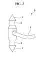
- FIG. 2 is a schematic view showing the suture needle.
- the suture needle 2 is a needle having one end (first end) formed in the shape of a cone and the other end (second end) formed sharply.
- the ends 3 (first end) and 4 (second end) of the suture needle 2 are sharply formed in the shape of a cone. That is, both of the ends 3 and 4 of the suture needle 2 can puncture living body tissue.
- two groove portions 5 engaged with a pair of needle locking portions 30 to be described below are formed between the ends 3 and 4 of the suture needle 2.
- Each groove portion 5 has an external diameter smaller than the maximum external diameter of the conical portion at the end of the suture needle 2.
- an end of the suture 6 is fixed between the respective groove portions 5 at an intermediate portion of the suture needle 2.
- the applicator 10 includes a treatment portion 11, a longitudinal member 50 that has the treatment portion 11 disposed at one end (first end) thereof, and an operating portion 60 disposed at the other end (second end) of the longitudinal member 50.
- a side on where the treatment portion 11 is disposed being defined as a distal end side
- a side where the operating portion 60 is disposed being defined a proximal end side, in the applicator 10.
- FIG. 3A is a plan view showing the treatment portion 11 in the suture device 1.
- FIG. 3B is a plan view showing a partial configuration in the treatment portion 11.
- FIG. 3C is a view showing the operation of the treatment portion 11 in the suture device 1.
- FIG. 4A is a cross-portional view taken along line A-A of FIG. 3A .
- FIG. 4B is a cross-portional view showing a state where the suture needle 2 and the needle locking portions 30 are detached in FIG. 4A .
- the treatment portion 11 has a pair of grasping members 12, the pair of needle locking portions 30 that are provided at the pair of grasping members 12, a cover member 39 that connects the pair of grasping members 12 to a longitudinal member 50, and a link member 40 that is connected to the longitudinal member 50.
- the pair of grasping members 12 includes a first grasping member 14 and a second grasping member 15 that are relatively rotatably connected together by a pin 13 at a proximal end.
- the first grasping member 14 and the second grasping member 15 rotate relative to each other with a central axis of the pin 13 as a rotation center. This allows the pair of grasping members 12 to perform an opening and closing operation.
- the first grasping member 14 is formed with a first grasping surface 17 for grasping living body tissue
- the second grasping member 15 is formed with a second grasping surface 18 for grasping the living body tissue.
- a depression 19 formed so as to be depressed in a direction orthogonal to the first grasping surface 17 is formed in the first grasping surface 17 in order to support the suture needle 2.
- a depression 20 formed so as to be depressed in a direction orthogonal to the second grasping surface 18 is formed in the second grasping surface 18 in order to support the suture needle 2.
- the depressions 19 and 20 formed in the first grasping surface 17 and the second grasping surface 18 have a shape that resembles the shape of the ends 3 and 4 of the suture needle 2.
- the ends 3 and 4 of the suture needle 2 fit into the depressions 19 and 20.
- Links 25 are respectively connected to proximal ends of the pair of grasping members 12. Moreover, an opening-closing wire 26 (power transmitting member) is fixed to the links 25.
- the links 25 are provided in order to convert advance/retraction operation of the opening-closing wire 26 into the opening and closing operation of the pair of grasping members 12.
- the opening-closing wire 26 has a distal end connected to the pair of grasping members 12 via the links 25, and has a proximal end connected to the operating portion 60 (refer to FIG. 1 ).
- the opening-closing wire 26 is a wire rod (for example, a stranded wire) fixed to a proximal end of the link 25, and is inserted into a coiled sheath 52 (refer to FIG. 7 ) inside the longitudinal member 50.
- the pair of needle locking portions 30 are respectively disposed inside the pair of grasping members 12.
- the pair of grasping members 12 are provided with grooves 21 and 22 into which the needle locking portions 30 are inserted, and lids 23 and 24 that close the grooves 21 and 22, respectively.
- the grooves 21 and 22 are formed so as to extend from distal ends of the pair of grasping members 12 toward the proximal ends thereof, and distal ends of grooves 21 and 22 are open.
- a first needle locking member 31 that is a plate-like member that constitutes the pair of needle locking portions 30 is inserted into the groove 21.
- the first needle locking member 31 is formed with a through-hole 33 passed therethrough in a thickness direction and a locking hole portion 35 formed to be connected to the through-hole 33.
- the through-hole 33 has an internal diameter having almost the same size as the internal diameter of the depression 19 (refer to FIGS. 4A and 4B ) formed in the pair of grasping members 12.
- One of the ends 3 and 4 of the suture needle 2 is insertable into the through-hole 33.
- the width of the locking hole portion 35 is smaller than the internal diameter of the through-hole 33 and is greater than the external diameter of the groove portion 5 formed in the suture needle 2. Additionally, the locking hole portion 35 is arranged on the proximal end side of the through-hole 33. Accordingly, if the locking hole portion 35 enters the groove portion 5 of the suture needle 2, one of the ends 3 and 4 of the suture needle 2 is locked to the first needle locking member 31.
- the second needle locking member 32 that is a plate-like member that constitutes the pair of needle locking portions 30 is inserted into the groove 22.
- the second needle locking member 32 is formed with a through-hole 34 that is the same as the above-described through-hole 33, and a locking hole portion 36 that is the same as the above-described locking hole portion 35.
- the second needle locking member 32 is formed with the same shape and size as the first needle locking member 31. The shapes of the second needle locking member 32 and the first needle locking member 31 may be different from each other.
- passing wires 37 are fixed to the proximal ends of the pair of needle locking portions 30. That is, a distal end of a first passing wire 37A (first linear member) is fixed to a proximal end of the first needle locking member 31, and a distal end of a second passing wire 37B (second linear member) is fixed to a proximal end of the second needle locking member 32.
- the passing wire 37 is arranged at a position apart from the link 25 so as to avoid the link 25.
- the passing wire 37 In the passing wire 37, a range from the pin 13, which connects the pair of grasping members 12 together and is an opening-closing shaft in the pair of grasping members 12, to the distal end of the passing wire 37 is covered with a hard pipe 38. Accordingly, the passing wire 37 has flexibility in a portion B (refer to FIGS. 3A, 3B, and 3C ) that is bent by the opening and closing operation of the pair of grasping members 12 (refer to FIG. 3A ), and has high rigidity such that the passing wire does not easily buckle closer to the distal end side than the portion B.
- the pipe 38 that covers the passing wire 37 may be a material that is harder than the passing wire 37, or may be a pipe that has the same hardness as the passing wire 37. That is, the pipe 38 that covers the passing wire 37 just has to be capable of reinforcing the passing wire 37.
- the cover member 39 is a tubular member that is fixed to a distal end of the longitudinal member 50.
- the cover member 39 holds both ends of the pin 13.
- the links 25 and the opening-closing wire 26 that open and close the pair of grasping members 12 are inserted into the cover member 39.
- An outer peripheral surface of the cover member 39 is formed with a slit 39a for keeping the pair of grasping members 12 and the links 25 from interfering with the cover member 39 during the opening and closing operation of the pair of grasping members 12.
- FIG. 5 is a perspective view showing the link member 40. As illustrated in FIG. 5 , the link member 40 has an annular body 41, rotatable supporting portions 42 and 43, and a pair of connecting portions 44 and 45.
- the body 41 is rotated with respect to the cover member 39 with a central axis of the rotatable supporting portions 42 and 43 as a rotation center.
- the opening-closing wire 26 and the passing wires 37 are inserted inside the body 41 that is annularly formed.
- the rotatable supporting portions 42 and 43 are formed in a columnar shape of which a central axis extends in a direction intersecting the longitudinal axis of the longitudinal member 50.
- the shape of the rotatable supporting portions 42 and 43 may be shapes other than the columnar shape without being limited to the columnar shape.
- the rotatable supporting portions 42 and 43 are provided for the purpose of connecting the body 41 to the cover member 39.
- the central axis X of the rotatable supporting portions 42 and 43 is directed to the direction orthogonal to the longitudinal axis of the longitudinal member 50.
- the rotatable supporting portions 42 and 43 are arranged in two places that face each other with the center of the annular body 41 therebetween.
- the rotatable supporting portions 42 and 43 are fixed to the body 41. Moreover, ends 42a and 43a directed to the inside of the body 41 in the rotatable supporting portions 42 and 43 are inserted into the cover member 39 (refer to FIG. 3A ). Accordingly, as illustrated in FIG. 3A , the body 41 is connected to the cover member 39 by the rotatable supporting portions 42 and 43. That is, in the present embodiment, the rotatable supporting portions 42 and 43 connect the link member 40 and the longitudinal member 50 via the cover member 39.
- the connecting portions 44 and 45 are two rod-shaped members that extend parallel to each other, and the passing wires 37 are inserted into the body 41. Respective rod-shaped members that constitute the connecting portions 44 and 45 are relatively rotatable with respect to the body 41 with respective central axes X' and X" as rotation centers.
- each rod-shaped member in a central axis direction is formed with a hole 44a or 45a of which a centerline extends in a direction orthogonal to the central axis.
- the two passing wires 37 (the first passing wire 37A and the second passing wire 37B) are respectively inserted into the holes 44a and 45a formed in the respective rod-shaped members that constitute the connecting portions 44 and 45.
- the connecting portions 44 and 45 maintain the passing wires 37 substantially parallel to the longitudinal axis of the longitudinal member 50 regardless of the rotational angle of the body 41 itself.
- the connecting portions 44 and 45 may not be the rod-shaped members, and the same effects are obtained as long as the connecting portions are relatively rotatable with respect to the body 41.
- a tubular member 46 is fixed to the passing wire 37A inserted into the holes 44a and 45a of the connecting portions 44 and 45.
- the second passing wire 37B is also provided with the same configuration as the tubular member 46.
- the passing wire 37 is inserted into the tubular member 46. Moreover, the tubular member 46 abuts against an opening end of the hole 44a at that is formed in the connecting portion 44. As the tubular member 46 abuts against the opening end of the connecting portion 44, the passing wire 37 is positioned with respect to the connecting portion 44. A tubular member 46a of the tubular member 46 disposed on the distal end side of the connecting portion 44 is fixed to the passing wire 37 by a fixing method having strength such that the passing wire 37 can withstand a pulling force when being towed to the proximal end side.
- a tubular member 46b of the tubular member 46 disposed on the proximal end side of the connecting portion 44 is fixed to the passing wire 37 by a fixing method having strength such that the passing wire 37 can withstand a pressing force when being pressed to the distal end side by the connecting portion 44.
- a frictional resistance caused on the passing wire 37 closer to the proximal end side than the link member 40 is greater than a frictional resistance caused on the passing wire 37 closer to the distal end side than the link member 40.
- a frictional resistance to the passing wire 37 within the longitudinal member 50 increases.
- a difference in magnitude between the frictional resistances becomes remarkable.
- a fixing method in which the tubular member 46a disposed on the distal end side of the connecting portion 44 or 45 has a higher strength than the tubular member 46b disposed on the proximal end side of the connecting portion 44 or 45 is adopted.
- the tubular member 46a disposed on the distal end side of the connecting portion 44 or 45 is fixed to the passing wire 37 by laser welding.
- the tubular member 46b disposed on the proximal end side of the connecting portion 44 or 45 is fixed to the passing wire 37 by brazing or the like.
- the fixing methods of the respective tubular members 46 to the passing wires 37 may be different from the fixing methods in consideration of workability.
- FIG. 6 is a front view of the treatment portion.
- the link member 40 that is hidden by the pair of grasping members 12, the cover member 39, or the like and is originally invisible is deliberately illustrated.
- the link member 40 has a positional relationship in which the whole link member 40 is shifted in a circumferential direction with respect to a median line L of the pair of grasping members 12.
- the passing wires 37 are brought into a linear state of being parallel to the longitudinal axis of the longitudinal member 50, in the regions from the pair of grasping members 12 to the holes 44a and 45a of the connecting portions 44 and 45.
- FIG. 7 is a cross-portional view showing a cross-portion orthogonal to the longitudinal axis of the longitudinal member.
- the longitudinal member 50 has an outer sheath 51 made of resin, and the coiled sheath 52 inserted into the outer sheath 51.
- the outer sheath 51 and the coiled sheath 52 that constitute the longitudinal member 50 are flexible members having the longitudinal axis.
- the outer sheath 51 is a tubular member that has an external diameter such that the outer sheath is insertable through a treatment tool channel (designated by reference numeral 101 in FIG. 1 ) of the endoscope.
- An outer surface of the outer sheath 51 is in a surface state where a frictional resistance to the inner surface of the treatment tool channel 101 is low.
- the coiled sheath 52 is a sheath in which a wire rod is wound in a coil form with the longitudinal axis of the longitudinal member 50 as a center, and is a sheath in which flexibility, and resistance against compression in the direction of the longitudinal axis are balanced.
- the opening-closing wire 26 is inserted into the coiled sheath 52.
- a centerline of the outer sheath 51 is shifted in parallel from a centerline of the coiled sheath 52.
- second coiled sheaths 53 and 54 are arranged between the outer sheath 51 and the coiled sheath 52.
- the second coiled sheaths 53 and 54 are tubular members through which the passing wires 37 are inserted.
- the second coiled sheaths 53 and 54 are arranged adjacent to each other inside the longitudinal member 50. Accordingly, as compared to a case where the second coiled sheaths 53 and 54 are disposed at positions that face each other in a radial direction of the coiled sheath 52, the maximum external diameter of a bundle of the coiled sheath 52 and the second coiled sheaths 53 and 54 can be made smaller. Accordingly, for example, as illustrated in FIG.
- the wall thickness d1 of the outer sheath 51 can be increased without enlarging the external diameter of the outer sheath 51, as illustrated in FIG. 7 . For this reason, reduction in the diameter of the longitudinal member 50, and buckling prevention of the longitudinal member 50 can be made compatible.
- opening ends of the second coiled sheaths 53 and 54 on the distal end side are disposed at positions apart further toward the proximal end side than the link member 40.
- the passing wires 37 extending from the opening ends of the second coiled sheaths 53 and 54 on the distal end side respectively extend toward the holes 44a and 45a formed in the respective connecting portions 44 and 45 provided in the link member 40 (refer to FIGS. 4A and 4B ).
- the operating portion 60 includes a first slider 61 for pushing and pulling the opening-closing wire 26, and second sliders 62 and 63 for pulling the passing wires 37, respectively.
- the proximal end of the opening-closing wire 26 is fixed to the first slider 61.
- the second slider 62 is a slider for pulling the first passing wire 37A.
- the second slider 63 is a slider for pulling the second passing wire 37B. Proximal ends of the passing wires 37 are fixed to the second sliders 62 and 63, respectively.
- the operating portion 60 is an opening-closing operating portion that performs the operation of transmitting power to the opening-closing wire 26 in order to perform the opening and closing operation of the pair of grasping members 12, and is a needle locking and operating portion that performs the operation of moving the passing wires 37 along the longitudinal axis of the longitudinal member 50, to lock or release the suture needle 2 to or from the needle locking portions 30.
- the configuration of the operating portion 60 is not limited to the configuration that has the first slider 61 and the second sliders 62 and 63.
- a configuration in which the opening-closing wire 26 or the passing wires 37 are moved using a lever, a configuration in which the opening-closing wire 26 or the passing wires 37 are wound around a rotating shaft and moved, or the like may be adopted as the operating portion 60.
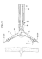
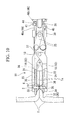
- FIGS. 9 and 10 are explanatory views showing a process when the suture device 1 is used.
- FIG. 11 is a schematic view for describing the actions of the suture device 1.
- the suture device 1 is prepared in a state where the suture needle 2 is attached to one of a pair of grasping members 12 (the second grasping member 15 in FIG. 9 ) provided in the suture device 1.
- the suture device 1, as illustrated in FIG. 1 is inserted into the treatment tool channel 101 of the endoscope 100 from the treatment portion 11 side, and is guided to a target region that is a target where living body tissue is to be sutured.
- the suture device 1 of the present embodiment if the pulling force of the first slider 61 illustrated in FIG. 1 is lessened, the grasping of the living body tissue between the first grasping surface 17 and the second grasping surface 18 is released. Additionally, if the first slider 61 is moved to the distal end side, the pair of grasping members 12 are opened. In this case, the suture needle 2 is still in a state where the suture needle is attached to the second grasping member 15. Accordingly, the living body tissue can be punctured again by the suture needle 2.
- the living body tissue can be moved or the orientation of the living body tissue can also be changed similar to grasping forceps that only grips the living body tissue, by grasping the living body tissue with a force of such a degree that the suture needle 2 does not penetrate the living body tissue while pulling the first slider 61.
- the suture needle 2 is pulled out from a side where puncturing is made by the suture needle 2 to a side opposite to the puncturing side, in a state where the living body tissue is punctured by the suture needle 2.
- a slider which is located closer to the distal end side out of the two sliders provided as the second sliders 62 and 63 in the operating portion 60 illustrated in FIG. 1 , is pulled by manual work or the like.
- the second slider 63 to which the second passing wire 37B is fixed is pulled.
- the connecting portion 45 of the link member 40 is moved to the proximal end side. Since the link member 40 is rotatable with respect to the cover member 39 by the rotatable supporting portions 42 and 43, if the connecting portion 45 is moved to the proximal end side, the connecting portion 44 is reversely moved to the distal end side. That is, the portion of the first passing wire 37A closer to the distal end side than the link member 40 is pressed to the distal end side, and the portion of the first passing wire 37A closer to the proximal end side than the link member 40 is pulled to the distal end side. That is, the first passing wire 37A is moved to the distal end side as a whole by the action of the link member 40.
- the first needle locking member 31 to which the distal end of the first passing wire 37A is fixed is pressed by the first passing wire 37A and is moved to the distal end side. Then, the first needle locking member 31 moves so that the locking hole portion 35 enters the groove portion 5. Accordingly, the suture needle 2 is locked to the first needle locking member 31.
- the second needle locking member 32 to which the distal end of the second passing wire 37B is fixed is moved to the proximal end side by pulling the second passing wire 37B. Then, the second needle locking member 32 moves so that the locking hole portion 36 separates from the groove portion 5. Accordingly, the suture needle 2 can be removed from the second needle locking member 32.
- the suture needle 2 moves in a state where the suture needle is locked to the first grasping member 14, penetrates the living body tissue, and is pulled out. As a result, the suture 6 fixed to the suture needle 2 is inserted into the living body tissue.
- the first passing wire 37A is located closer to the first grasping member 14 side than the pin 13
- the second passing wire 37B is located closer to the second grasping member 15 side than the pin 13. Accordingly, when the pair of grasping members 12 are opened, the pair of needle locking portions 30 are pressed so that the pair of needle locking portions 30 relatively advance with respect to the pair of grasping members 12. As a result, the locking hole portion of the first needle locking member 31 or the second needle locking member 32 enters the groove portion 5 formed in the suture needle 2, and the suture needle 2 does not come off in slight advance/retraction movement of the second sliders 62 and 63.
- the suture 6 is tied if necessary and a series of treatment is ended.
- the suture 6 may be inserted again into the living body tissue if necessary after the suture needle 2 is passed from the second grasping member 15 to the first grasping member 14.
- the suture needle when the suture needle is passed from the second grasping member 15 to the first grasping member 14, the pair of grasping members 12 are closed, and the second passing wire 37B is moved to the proximal end side in the operating portion 60. Accordingly, the suture needle 2 can be removed from the second needle locking member 32 provided at the second grasping member 15, and simultaneously, the suture needle 2 is locked to the first grasping member 14 by the first needle locking member 31 provided at the first grasping member 14.
- the suture device 1 of the present embodiment can grip living body tissue in order to suture the living body tissue and pass the suture needle 2 between the pair of grasping members 12, and can also open the grasping members 12 again without passing the suture needle 2 once the living body tissue is gripped. Accordingly, a function as forceps that grips living body tissue, and a function as a device that sutures the living body tissue can be made compatible.
- the suture device 1 can be inserted into a treatment tool channel of a flexible endoscope and the suture device 1 can be used, a treatment tool of the suture device 1 can be easily guided to a part to be sutured in a case where a part that requires suturing of living body tissue is discovered when examination is performed using the flexible endoscope.
- living body tissue in the vicinity of a part to be sutured can be moved or the part to be sutured can be sutured without separately preparing grasping forceps.
- working efficiency is excellent.
- a suturing position can be easily changed.
- the above embodiment can be preferably applied to suture devices that suture living body tissue.
Landscapes
- Health & Medical Sciences (AREA)
- Life Sciences & Earth Sciences (AREA)
- Surgery (AREA)
- Heart & Thoracic Surgery (AREA)
- Engineering & Computer Science (AREA)
- Biomedical Technology (AREA)
- Nuclear Medicine, Radiotherapy & Molecular Imaging (AREA)
- Medical Informatics (AREA)
- Molecular Biology (AREA)
- Animal Behavior & Ethology (AREA)
- General Health & Medical Sciences (AREA)
- Public Health (AREA)
- Veterinary Medicine (AREA)
- Surgical Instruments (AREA)
- Sewing Machines And Sewing (AREA)
Abstract
Description
- The present invention relates to a suture device for medical use.
- Priority is claimed on United States Patent Application No.
61/693,028 - Conventionally, suture devices for performing suturing within a body are known. For example, an automatic needle pass suture device is disclosed in Published Japanese Translation No.
2001-500765 2001-500765 - [Patent Document 1] Published Japanese Translation No.
2001-500765 - Conventionally, in suture devices that passes a suture needle between a pair of grasping members, the opening and closing of the grasping members and the passing of the suture needle are interlocked with each other, and once the pair of grasping members is closed, the suture needle is automatically passed to the grasping member on the opposite side. For this reason, it is not possible to grip the grasping members to close living body tissue and hold the living body tissue again. Additionally, although there is known a flexible endoscope equipped with one or a plurality of treatment tool channels through which treatment tools are insertable, if there are too many treatment tool channels, the external diameter of an insertion portion becomes thick, and workability deteriorates. For this reason, it is desirable to effectively use a limited number of treatment tool channels.
- The invention has been made in view of the above problems, and an object thereof is a suture device that can grip living body tissue in order to suture the living body tissue and pass the suture needle between the pair of grasping members and can also open the grasping members again without passing the suture needle once the living body tissue is gripped.
- A suture device related to a first aspect of the present invention includes a longitudinal member which is provided to extend along a longitudinal axis; a pair of grasping members which are provided at a distal end of the longitudinal member and include a first grasping member and a second grasping member that is capable of performing an opening and closing operation in order to treat a target region; a suture needle which is engaged with the pair of grasping members in order to puncture tissue between the pair of grasping members; a power transmitting member which extends along the longitudinal axis and which has a distal end portion connected to the pair of grasping members in order to transmit power for opening and closing the pair of grasping members to the pair of grasping members; an opening-closing operating portion which operates the power transmitting member so that the power is generated in the power transmitting member; a pair of needle locking portions which have a first needle locking member provided so as to be movable with respect to the first grasping member and a second needle locking member provided so as to be movable with respect to the second grasping member, and which lock or release the suture needle to or from the pair of grasping members according to the movement of the needle locking portions with respect to the pair of grasping members; a pair of linear members which have a first linear member connected to the first needle locking member and a second linear member connected to the second needle locking member, in order to relatively move the pair of needle locking portions with respect to the pair of grasping members, and which are arranged so as to be movable with respect to the power transmitting member along the longitudinal axis; a needle locking and operating portion which is provided at proximal ends of the pair of linear members and operate so as to move the pair of linear members along the longitudinal axis; a link member which is provided at a distal end portion of the longitudinal member, has a first end fixed to a first linear member, and has a second end fixed to a second linear member; and a rotatable supporting portion which rotatably supports the link member around a rotation shaft extending in an axial direction intersecting the longitudinal axis between the first linear member and the second linear member so that the second linear member advances to the pair grasping member side when the first linear member is pulled to the proximal end side by the operation of the needle locking and operating portion.
- In the suture device related to a second aspect of the present invention based on the above first aspect, as the link member is rotated around the rotation shaft and the second linear member is moved to the side of the pair of grasping members according to the operation of pulling the first linear member using the needle locking and operating portion, the suture needle is locked to the first needle locking member and the lock of the suture needle to the second needle locking member is released.
- In the suture device related to a third aspect of the present invention based on the above second aspect, the link member has a curved shape along a circumferential direction around the longitudinal axis.
- In the suture device related to a fourth aspect of the present invention based on the above first aspect, the link member includes an annular body that is open in a direction of the longitudinal axis and has the rotation shaft, and a connecting portion that is connected to the body so as to be rotatable with respect to the body, with an axis parallel to a rotation center of the rotation shaft as a rotation center and is formed with a through-hole through which the linear member is inserted, and a tubular member, which abuts against an opening end of the through-hole and positions the linear member with respect to the connecting portion, is attached to the linear member.
- In the suture device related to a fifth aspect of the present invention based on the above first aspect, the linear member has flexibility, and the linear member is inserted into a hard pipe between an opening-closing shaft of the pair of grasping members in a direction of the longitudinal axis, and the distal end of the linear member is fixed to the pipe.
- In the suture device related to a sixth aspect of the present invention based on the above first aspect, the grasping member has a conical depression for supporting the suture needle, and the suture needle has a conical end that fits into the depression, and a groove portion that is adjacent to the end and has a diameter smaller than the end, and the needle locking portion has a through-hole through which the end is insertable, and a locking hole portion that is formed so as to be connected to the through-hole, and has a width that is smaller than the internal diameter of the through-hole and greater than the external diameter of the groove portion.
- According to the respective aspects of the above present invention, it is possible to provide a suture device that can grip living body tissue in order to suture the living body tissue and pass the suture needle between the pair of grasping members and can also open the grasping members again without passing the suture needle once the living body tissue is gripped. Accordingly, a function as forceps that grips living body tissue, and a function as a device that sutures the living body tissue can be made compatible.
-
-
FIG. 1 is an overall view showing a suture device of an embodiment of the present invention. -
FIG. 2 is a schematic view showing a suture needle. -
FIG. 3A is a plan view showing a treatment portion in the suture device. -
FIG. 3B is a plan view showing the configuration of a portion of the treatment portion. -
FIG. 3C is an explanatory view for describing the operation of the treatment portion. -
FIG. 4A is a cross-portional view taken along line A-A ofFIG. 3A . -
FIG. 4B is a cross-portional view showing a state where the suture needle and a needle locking portion are not attached inFIG. 4A . -
FIG. 5 is a perspective view showing a link member. -
FIG. 6 is a front view of the treatment portion. -
FIG. 7 is a cross-portional view showing a cross-portion orthogonal to a longitudinal axis of a longitudinal member. -
FIG. 8 is a reference view for comparison with the configuration illustrated inFIG. 7 . -
FIG. 9 is an explanatory view showing a process when the suture device is used. -
FIG. 10 is an explanatory view showing the process when the suture device is used. -
FIG. 11 is a schematic view for describing the actions of the suture device. - A suture device of an embodiment of the present invention will be described.
-
FIG. 1 is an overall view showing a suture device of an embodiment of the present invention. As illustrated inFIG. 1 , thesuture device 1 is a device that is used together with anendoscope 100 and sutures living body tissue using asuture 6. Thesuture device 1 includes asuture needle 2 to which thesuture 6 is attached, and anapplicator 10 for puncturing living body tissue with thesuture needle 2. -
FIG. 2 is a schematic view showing the suture needle. As illustrated inFIG. 2 , thesuture needle 2 is a needle having one end (first end) formed in the shape of a cone and the other end (second end) formed sharply. In the present embodiment, the ends 3 (first end) and 4 (second end) of thesuture needle 2 are sharply formed in the shape of a cone. That is, both of theends suture needle 2 can puncture living body tissue. Additionally, twogroove portions 5 engaged with a pair ofneedle locking portions 30 to be described below are formed between theends suture needle 2. Eachgroove portion 5 has an external diameter smaller than the maximum external diameter of the conical portion at the end of thesuture needle 2. Additionally, an end of thesuture 6 is fixed between therespective groove portions 5 at an intermediate portion of thesuture needle 2. - As illustrated in
FIG. 1 , theapplicator 10 includes atreatment portion 11, alongitudinal member 50 that has thetreatment portion 11 disposed at one end (first end) thereof, and anoperating portion 60 disposed at the other end (second end) of thelongitudinal member 50. Hereinafter, a description will be made with a side on where thetreatment portion 11 is disposed being defined as a distal end side, and a side where theoperating portion 60 is disposed being defined a proximal end side, in theapplicator 10. -
FIG. 3A is a plan view showing thetreatment portion 11 in thesuture device 1.FIG. 3B is a plan view showing a partial configuration in thetreatment portion 11.FIG. 3C is a view showing the operation of thetreatment portion 11 in thesuture device 1.FIG. 4A is a cross-portional view taken along line A-A ofFIG. 3A .FIG. 4B is a cross-portional view showing a state where thesuture needle 2 and theneedle locking portions 30 are detached inFIG. 4A . - As illustrated in
FIGS. 3A ,4A , and4B , thetreatment portion 11 has a pair of graspingmembers 12, the pair ofneedle locking portions 30 that are provided at the pair of graspingmembers 12, acover member 39 that connects the pair of graspingmembers 12 to alongitudinal member 50, and alink member 40 that is connected to thelongitudinal member 50. - The pair of grasping
members 12 includes a first graspingmember 14 and a second graspingmember 15 that are relatively rotatably connected together by apin 13 at a proximal end. The first graspingmember 14 and the second graspingmember 15 rotate relative to each other with a central axis of thepin 13 as a rotation center. This allows the pair of graspingmembers 12 to perform an opening and closing operation. - The first grasping
member 14 is formed with a first graspingsurface 17 for grasping living body tissue, and the second graspingmember 15 is formed with a second graspingsurface 18 for grasping the living body tissue. Adepression 19 formed so as to be depressed in a direction orthogonal to the first graspingsurface 17 is formed in the first graspingsurface 17 in order to support thesuture needle 2. Adepression 20 formed so as to be depressed in a direction orthogonal to the second graspingsurface 18 is formed in the second graspingsurface 18 in order to support thesuture needle 2. - The
depressions surface 17 and the second graspingsurface 18 have a shape that resembles the shape of theends suture needle 2. The ends 3 and 4 of thesuture needle 2 fit into thedepressions -
Links 25 are respectively connected to proximal ends of the pair of graspingmembers 12. Moreover, an opening-closing wire 26 (power transmitting member) is fixed to thelinks 25. Thelinks 25 are provided in order to convert advance/retraction operation of the opening-closing wire 26 into the opening and closing operation of the pair of graspingmembers 12. The opening-closing wire 26 has a distal end connected to the pair of graspingmembers 12 via thelinks 25, and has a proximal end connected to the operating portion 60 (refer toFIG. 1 ). The opening-closing wire 26 is a wire rod (for example, a stranded wire) fixed to a proximal end of thelink 25, and is inserted into a coiled sheath 52 (refer toFIG. 7 ) inside thelongitudinal member 50. - As illustrated in
FIGS. 4A and4B , the pair ofneedle locking portions 30 are respectively disposed inside the pair of graspingmembers 12. Specifically, the pair of graspingmembers 12 are provided withgrooves needle locking portions 30 are inserted, andlids grooves - The
grooves members 12 toward the proximal ends thereof, and distal ends ofgrooves - As illustrated in
FIGS. 4A and4B , a firstneedle locking member 31 that is a plate-like member that constitutes the pair ofneedle locking portions 30 is inserted into thegroove 21. - As illustrated in
FIG. 3B , the firstneedle locking member 31 is formed with a through-hole 33 passed therethrough in a thickness direction and alocking hole portion 35 formed to be connected to the through-hole 33. The through-hole 33 has an internal diameter having almost the same size as the internal diameter of the depression 19 (refer toFIGS. 4A and4B ) formed in the pair of graspingmembers 12. One of theends suture needle 2 is insertable into the through-hole 33. - The width of the
locking hole portion 35 is smaller than the internal diameter of the through-hole 33 and is greater than the external diameter of thegroove portion 5 formed in thesuture needle 2. Additionally, the lockinghole portion 35 is arranged on the proximal end side of the through-hole 33. Accordingly, if thelocking hole portion 35 enters thegroove portion 5 of thesuture needle 2, one of theends suture needle 2 is locked to the firstneedle locking member 31. - As illustrated in
FIGS. 4A and4B , the secondneedle locking member 32 that is a plate-like member that constitutes the pair ofneedle locking portions 30 is inserted into thegroove 22. The secondneedle locking member 32 is formed with a through-hole 34 that is the same as the above-described through-hole 33, and alocking hole portion 36 that is the same as the above-describedlocking hole portion 35. In the present embodiment, the secondneedle locking member 32 is formed with the same shape and size as the firstneedle locking member 31. The shapes of the secondneedle locking member 32 and the firstneedle locking member 31 may be different from each other. - Additionally, as illustrated in
FIG. 3B , distal ends of passing wires 37 (linear members) are fixed to the proximal ends of the pair ofneedle locking portions 30. That is, a distal end of afirst passing wire 37A (first linear member) is fixed to a proximal end of the firstneedle locking member 31, and a distal end of asecond passing wire 37B (second linear member) is fixed to a proximal end of the secondneedle locking member 32. The passingwire 37 is arranged at a position apart from thelink 25 so as to avoid thelink 25. - In the passing
wire 37, a range from thepin 13, which connects the pair of graspingmembers 12 together and is an opening-closing shaft in the pair of graspingmembers 12, to the distal end of the passingwire 37 is covered with ahard pipe 38. Accordingly, the passingwire 37 has flexibility in a portion B (refer toFIGS. 3A, 3B, and 3C ) that is bent by the opening and closing operation of the pair of grasping members 12 (refer toFIG. 3A ), and has high rigidity such that the passing wire does not easily buckle closer to the distal end side than the portion B. Thepipe 38 that covers the passingwire 37 may be a material that is harder than the passingwire 37, or may be a pipe that has the same hardness as the passingwire 37. That is, thepipe 38 that covers the passingwire 37 just has to be capable of reinforcing the passingwire 37. - The
cover member 39 is a tubular member that is fixed to a distal end of thelongitudinal member 50. Thecover member 39 holds both ends of thepin 13. Thelinks 25 and the opening-closing wire 26 that open and close the pair of graspingmembers 12 are inserted into thecover member 39. An outer peripheral surface of thecover member 39 is formed with aslit 39a for keeping the pair of graspingmembers 12 and thelinks 25 from interfering with thecover member 39 during the opening and closing operation of the pair of graspingmembers 12. -
FIG. 5 is a perspective view showing thelink member 40. As illustrated inFIG. 5 , thelink member 40 has anannular body 41,rotatable supporting portions portions - As illustrated in
FIGS. 3A ,4A , and4B , thebody 41 is rotated with respect to thecover member 39 with a central axis of therotatable supporting portions closing wire 26 and the passingwires 37 are inserted inside thebody 41 that is annularly formed. - As illustrated in
FIG. 5 , therotatable supporting portions longitudinal member 50. In addition, the shape of therotatable supporting portions portions body 41 to thecover member 39. In the present embodiment, the central axis X of therotatable supporting portions longitudinal member 50. Additionally, therotatable supporting portions annular body 41 therebetween. - The rotatable supporting
portions body 41. Moreover, ends 42a and 43a directed to the inside of thebody 41 in therotatable supporting portions FIG. 3A ). Accordingly, as illustrated inFIG. 3A , thebody 41 is connected to thecover member 39 by therotatable supporting portions rotatable supporting portions link member 40 and thelongitudinal member 50 via thecover member 39. - As illustrated in
FIG. 5 , the connectingportions wires 37 are inserted into thebody 41. Respective rod-shaped members that constitute the connectingportions body 41 with respective central axes X' and X" as rotation centers. - The center of each rod-shaped member in a central axis direction is formed with a
hole first passing wire 37A and thesecond passing wire 37B) are respectively inserted into theholes portions - Since the
body 41 and the connectingportions portions wires 37 substantially parallel to the longitudinal axis of thelongitudinal member 50 regardless of the rotational angle of thebody 41 itself. - The connecting
portions body 41. - As illustrated in
FIGS. 4A and4B , atubular member 46 is fixed to the passingwire 37A inserted into theholes portions second passing wire 37B is also provided with the same configuration as thetubular member 46. - The passing
wire 37 is inserted into thetubular member 46. Moreover, thetubular member 46 abuts against an opening end of thehole 44a at that is formed in the connectingportion 44. As thetubular member 46 abuts against the opening end of the connectingportion 44, the passingwire 37 is positioned with respect to the connectingportion 44. Atubular member 46a of thetubular member 46 disposed on the distal end side of the connectingportion 44 is fixed to the passingwire 37 by a fixing method having strength such that the passingwire 37 can withstand a pulling force when being towed to the proximal end side. Additionally, atubular member 46b of thetubular member 46 disposed on the proximal end side of the connectingportion 44 is fixed to the passingwire 37 by a fixing method having strength such that the passingwire 37 can withstand a pressing force when being pressed to the distal end side by the connectingportion 44. - A frictional resistance caused on the passing
wire 37 closer to the proximal end side than thelink member 40 is greater than a frictional resistance caused on the passingwire 37 closer to the distal end side than thelink member 40. Particularly, if the length of thelongitudinal member 50 increases, a frictional resistance to the passingwire 37 within thelongitudinal member 50 increases. Thus, a difference in magnitude between the frictional resistances becomes remarkable. For this reason, in the present embodiment, a fixing method in which thetubular member 46a disposed on the distal end side of the connectingportion tubular member 46b disposed on the proximal end side of the connectingportion tubular member 46a disposed on the distal end side of the connectingportion wire 37 by laser welding. Additionally, in the present embodiment, thetubular member 46b disposed on the proximal end side of the connectingportion wire 37 by brazing or the like. In addition, the fixing methods of the respectivetubular members 46 to the passingwires 37 may be different from the fixing methods in consideration of workability. -
FIG. 6 is a front view of the treatment portion. In addition, inFIG. 6 , in order to emphasize the positional relationship of thelink member 40, thelink member 40 that is hidden by the pair of graspingmembers 12, thecover member 39, or the like and is originally invisible is deliberately illustrated. As illustrated inFIG. 6 , in the present embodiment, thelink member 40 has a positional relationship in which thewhole link member 40 is shifted in a circumferential direction with respect to a median line L of the pair of graspingmembers 12. When the pair of graspingmembers 12 are in a fully closed state, the passingwires 37 are brought into a linear state of being parallel to the longitudinal axis of thelongitudinal member 50, in the regions from the pair of graspingmembers 12 to theholes portions -
FIG. 7 is a cross-portional view showing a cross-portion orthogonal to the longitudinal axis of the longitudinal member. As illustrated inFIG. 7 , thelongitudinal member 50 has anouter sheath 51 made of resin, and the coiledsheath 52 inserted into theouter sheath 51. Theouter sheath 51 and the coiledsheath 52 that constitute thelongitudinal member 50 are flexible members having the longitudinal axis. - The
outer sheath 51 is a tubular member that has an external diameter such that the outer sheath is insertable through a treatment tool channel (designated byreference numeral 101 inFIG. 1 ) of the endoscope. An outer surface of theouter sheath 51 is in a surface state where a frictional resistance to the inner surface of thetreatment tool channel 101 is low. - The coiled
sheath 52 is a sheath in which a wire rod is wound in a coil form with the longitudinal axis of thelongitudinal member 50 as a center, and is a sheath in which flexibility, and resistance against compression in the direction of the longitudinal axis are balanced. The opening-closing wire 26 is inserted into the coiledsheath 52. - A centerline of the
outer sheath 51 is shifted in parallel from a centerline of the coiledsheath 52. Moreover, in the present embodiment, second coiledsheaths outer sheath 51 and the coiledsheath 52. - The second
coiled sheaths wires 37 are inserted. The secondcoiled sheaths longitudinal member 50. Accordingly, as compared to a case where the second coiledsheaths sheath 52, the maximum external diameter of a bundle of the coiledsheath 52 and the second coiledsheaths FIG. 8 , as compared to the wall thickness d2 of anouter sheath 51 a when the second coiledsheaths sheath 52 therebetween, the wall thickness d1 of theouter sheath 51 can be increased without enlarging the external diameter of theouter sheath 51, as illustrated inFIG. 7 . For this reason, reduction in the diameter of thelongitudinal member 50, and buckling prevention of thelongitudinal member 50 can be made compatible. - Additionally, opening ends of the second coiled
sheaths link member 40. The passingwires 37 extending from the opening ends of the second coiledsheaths holes portions FIGS. 4A and4B ). - As illustrated in
FIG. 1 , the operatingportion 60 includes afirst slider 61 for pushing and pulling the opening-closing wire 26, andsecond sliders wires 37, respectively. The proximal end of the opening-closing wire 26 is fixed to thefirst slider 61. Thesecond slider 62 is a slider for pulling thefirst passing wire 37A. Thesecond slider 63 is a slider for pulling thesecond passing wire 37B. Proximal ends of the passingwires 37 are fixed to thesecond sliders - In the present embodiment, the operating
portion 60 is an opening-closing operating portion that performs the operation of transmitting power to the opening-closing wire 26 in order to perform the opening and closing operation of the pair of graspingmembers 12, and is a needle locking and operating portion that performs the operation of moving the passingwires 37 along the longitudinal axis of thelongitudinal member 50, to lock or release thesuture needle 2 to or from theneedle locking portions 30. - The configuration of the operating
portion 60 is not limited to the configuration that has thefirst slider 61 and thesecond sliders closing wire 26 or the passingwires 37 are moved using a lever, a configuration in which the opening-closing wire 26 or the passingwires 37 are wound around a rotating shaft and moved, or the like may be adopted as the operatingportion 60. - Next, the operation and actions when the
suture device 1 of the present embodiment is used will be described.FIGS. 9 and10 are explanatory views showing a process when thesuture device 1 is used.FIG. 11 is a schematic view for describing the actions of thesuture device 1. - The
suture device 1 is prepared in a state where thesuture needle 2 is attached to one of a pair of grasping members 12 (the second graspingmember 15 inFIG. 9 ) provided in thesuture device 1. Thesuture device 1, as illustrated inFIG. 1 , is inserted into thetreatment tool channel 101 of theendoscope 100 from thetreatment portion 11 side, and is guided to a target region that is a target where living body tissue is to be sutured. - If the
treatment portion 11 is guided to a part T that is a suturing target, living body tissue located at the part T that is the suturing target is gripped by pulling thefirst slider 61 illustrated inFIG. 1 to close the pair of graspingmembers 12 as illustrated inFIG. 10 . If the pair of graspingmembers 12 are closed, thesuture needle 2 attached to one (second grasping member 15) of the pair of graspingmembers 12 enter the depression (depression 19) formed in the grasping surface (first grasping surface 17) of the other (first grasping member 14) of the pair of graspingmembers 12. Accordingly, the living body tissue Ta that is present between the graspingsurfaces members 12 is punctured by thesuture needle 2. - Additionally, in the
suture device 1 of the present embodiment, if the pulling force of thefirst slider 61 illustrated inFIG. 1 is lessened, the grasping of the living body tissue between the first graspingsurface 17 and the second graspingsurface 18 is released. Additionally, if thefirst slider 61 is moved to the distal end side, the pair of graspingmembers 12 are opened. In this case, thesuture needle 2 is still in a state where the suture needle is attached to the second graspingmember 15. Accordingly, the living body tissue can be punctured again by thesuture needle 2. In addition, the living body tissue can be moved or the orientation of the living body tissue can also be changed similar to grasping forceps that only grips the living body tissue, by grasping the living body tissue with a force of such a degree that thesuture needle 2 does not penetrate the living body tissue while pulling thefirst slider 61. - In order to suture the living body tissue using the
suture needle 2 to which thesuture 6 is attached, thesuture needle 2 is pulled out from a side where puncturing is made by thesuture needle 2 to a side opposite to the puncturing side, in a state where the living body tissue is punctured by thesuture needle 2. In this case, a slider, which is located closer to the distal end side out of the two sliders provided as thesecond sliders portion 60 illustrated inFIG. 1 , is pulled by manual work or the like. In the present embodiment, thesecond slider 63 to which thesecond passing wire 37B is fixed is pulled. - Accordingly, on the distal end side of the
longitudinal member 50, as illustrated inFIG. 11 , the connectingportion 45 of thelink member 40 is moved to the proximal end side. Since thelink member 40 is rotatable with respect to thecover member 39 by therotatable supporting portions portion 45 is moved to the proximal end side, the connectingportion 44 is reversely moved to the distal end side. That is, the portion of thefirst passing wire 37A closer to the distal end side than thelink member 40 is pressed to the distal end side, and the portion of thefirst passing wire 37A closer to the proximal end side than thelink member 40 is pulled to the distal end side. That is, thefirst passing wire 37A is moved to the distal end side as a whole by the action of thelink member 40. - Inside the pair of grasping
members 12, the firstneedle locking member 31 to which the distal end of thefirst passing wire 37A is fixed is pressed by thefirst passing wire 37A and is moved to the distal end side. Then, the firstneedle locking member 31 moves so that thelocking hole portion 35 enters thegroove portion 5. Accordingly, thesuture needle 2 is locked to the firstneedle locking member 31. - Additionally, the second
needle locking member 32 to which the distal end of thesecond passing wire 37B is fixed is moved to the proximal end side by pulling thesecond passing wire 37B. Then, the secondneedle locking member 32 moves so that thelocking hole portion 36 separates from thegroove portion 5. Accordingly, thesuture needle 2 can be removed from the secondneedle locking member 32. - If the pair of grasping
members 12 are opened by moving thefirst slider 61 to the distal end side in this state, thesuture needle 2 moves in a state where the suture needle is locked to the first graspingmember 14, penetrates the living body tissue, and is pulled out. As a result, thesuture 6 fixed to thesuture needle 2 is inserted into the living body tissue. - Additionally, in the present embodiment, when the
treatment portion 11 is seen in a plan view, thefirst passing wire 37A is located closer to the first graspingmember 14 side than thepin 13, and thesecond passing wire 37B is located closer to the second graspingmember 15 side than thepin 13. Accordingly, when the pair of graspingmembers 12 are opened, the pair ofneedle locking portions 30 are pressed so that the pair ofneedle locking portions 30 relatively advance with respect to the pair of graspingmembers 12. As a result, the locking hole portion of the firstneedle locking member 31 or the secondneedle locking member 32 enters thegroove portion 5 formed in thesuture needle 2, and thesuture needle 2 does not come off in slight advance/retraction movement of thesecond sliders - Then, the
suture 6 is tied if necessary and a series of treatment is ended. In addition, thesuture 6 may be inserted again into the living body tissue if necessary after thesuture needle 2 is passed from the second graspingmember 15 to the first graspingmember 14. - In summary, when the suture needle is passed from the second grasping
member 15 to the first graspingmember 14, the pair of graspingmembers 12 are closed, and thesecond passing wire 37B is moved to the proximal end side in the operatingportion 60. Accordingly, thesuture needle 2 can be removed from the secondneedle locking member 32 provided at the second graspingmember 15, and simultaneously, thesuture needle 2 is locked to the first graspingmember 14 by the firstneedle locking member 31 provided at the first graspingmember 14. - The
suture device 1 of the present embodiment can grip living body tissue in order to suture the living body tissue and pass thesuture needle 2 between the pair of graspingmembers 12, and can also open the graspingmembers 12 again without passing thesuture needle 2 once the living body tissue is gripped. Accordingly, a function as forceps that grips living body tissue, and a function as a device that sutures the living body tissue can be made compatible. - Additionally, since the
suture device 1 can be inserted into a treatment tool channel of a flexible endoscope and thesuture device 1 can be used, a treatment tool of thesuture device 1 can be easily guided to a part to be sutured in a case where a part that requires suturing of living body tissue is discovered when examination is performed using the flexible endoscope. - Particularly, in endoscopes in which only one treatment tool channel is provided, living body tissue in the vicinity of a part to be sutured can be moved or the part to be sutured can be sutured without separately preparing grasping forceps. Thus, working efficiency is excellent. Additionally, once living body tissue is gripped, a suturing position can be easily changed.
- While an example of the preferred embodiment of the present invention has been described above, the present invention is not limited to the above embodiment. Additions, omissions, substitutions, and other modifications of components can be made without departing from the concept of the present invention.
- The above embodiment can be preferably applied to suture devices that suture living body tissue.
-
- 3,4: END
- 5: GROOVE PORTION
- 12: GRIPPING MEMBER
- 26: OPENING-CLOSING WIRE (POWER TRANSMITTING MEMBER)
- 30: NEEDLE LOCKING PORTION
- 33: THROUGH-HOLE
- 35: LOCKING HOLE PORTION
- 37: PASSING WIRE (LINEAR MEMBER)
- 38: PIPE
- 40: LINK MEMBER
- 41: BODY
- 42, 43: ROTATABLE SUPPORTING PORTION
- 44, 45: CONNECTING PORTION
- 46: TUBULAR MEMBER
- 50: LONGITUDINAL MEMBER
- 60: OPERATING PORTION (OPENING-CLOSING OPERATING PORTION, NEEDLE LOCKING AND OPERATING PORTION)
Claims (6)
- A suture device comprising:a longitudinal member which is provided to extend along a longitudinal axis;a pair of grasping members which are provided at a distal end of the longitudinal member and include a first grasping member and a second grasping member that is capable of performing an opening and closing operation in order to treat a target region;a suture needle which is engaged with the pair of grasping members in order to puncture tissue between the pair of grasping members;a power transmitting member which extends along the longitudinal axis and which has a distal end portion connected to the pair of grasping members in order to transmit power for opening and closing the pair of grasping members to the pair of grasping members;an opening-closing operating portion which operates the power transmitting member so that the power is generated in the power transmitting member;a pair of needle locking portions which have a first needle locking member provided so as to be movable with respect to the first grasping member and a second needle locking member provided so as to be movable with respect to the second grasping member, and which lock or release the suture needle to or from the pair of grasping members according to the movement of the needle locking portions with respect to the pair of grasping members;a pair of linear members which have a first linear member connected to the first needle locking member and a second linear member connected to the second needle locking member, in order to relatively move the pair of needle locking portions with respect to the pair of grasping members, and which are arranged so as to be movable with respect to the power transmitting member along the longitudinal axis;a needle locking and operating portion which is provided at proximal ends of the pair of linear members and operate so as to move the pair of linear members along the longitudinal axis;a link member which is provided at a distal end portion of the longitudinal member, has a first end fixed to a first linear member, and has a second end fixed to a second linear member; anda rotatable supporting portion which rotatably supports the link member around a rotation shaft extending in an axial direction intersecting the longitudinal axis between the first linear member and the second linear member so that the second linear member advances to the pair grasping member side when the first linear member is pulled to the proximal end side by the operation of the needle locking and operating portion.
- The suture device according to Claim 1,
wherein, as the link member is rotated around the rotation shaft and the second linear member is moved to the side of the pair of grasping members according to the operation of pulling the first linear member using the needle locking and operating portion, the suture needle is locked to the first needle locking member and the lock of the suture needle to the second needle locking member is released. - The suture device according to Claim 2,
wherein the link member has a curved shape along a circumferential direction around the longitudinal axis. - The suture device according to Claim 1,
wherein the link member includes an annular body that is open in a direction of the longitudinal axis and has the rotation shaft, and a connecting portion that is connected to the body so as to be rotatable with respect to the body, with an axis parallel to a rotation center of the rotation shaft as a rotation center and is formed with a through-hole through which the linear member is inserted, and
wherein a tubular member, which abuts against an opening end of the through-hole and positions the linear member with respect to the connecting portion, is attached to the linear member. - The suture device according to Claim 1,
wherein the linear member has flexibility, and
wherein the linear member is inserted into a hard pipe between an opening-closing shaft of the pair of grasping members in a direction of the longitudinal axis, and the distal end of the linear member is fixed to the pipe. - The suture device according to Claim 1,
wherein the grasping member has a conical depression for supporting the suture needle, and
wherein the suture needle has a conical end that fits into the depression, and a groove portion that is adjacent to the end and has a diameter smaller than the end, and
wherein the needle locking portion has a through-hole through which the end is insertable, and a locking hole portion that is formed so as to be connected to the through-hole, and has a width that is smaller than the internal diameter of the through-hole and greater than the external diameter of the groove portion.
Applications Claiming Priority (2)
| Application Number | Priority Date | Filing Date | Title |
|---|---|---|---|
| US201261693028P | 2012-08-24 | 2012-08-24 | |
| PCT/JP2013/071408 WO2014030544A1 (en) | 2012-08-24 | 2013-08-07 | Suture device |
Publications (3)
| Publication Number | Publication Date |
|---|---|
| EP2889008A1 true EP2889008A1 (en) | 2015-07-01 |
| EP2889008A4 EP2889008A4 (en) | 2016-05-18 |
| EP2889008B1 EP2889008B1 (en) | 2018-06-20 |
Family
ID=50149853
Family Applications (1)
| Application Number | Title | Priority Date | Filing Date |
|---|---|---|---|
| EP13831750.8A Active EP2889008B1 (en) | 2012-08-24 | 2013-08-07 | Suture device |
Country Status (5)
| Country | Link |
|---|---|
| US (1) | US9901336B2 (en) |
| EP (1) | EP2889008B1 (en) |
| JP (2) | JPWO2014030544A1 (en) |
| CN (1) | CN104582590B (en) |
| WO (1) | WO2014030544A1 (en) |
Cited By (6)
| Publication number | Priority date | Publication date | Assignee | Title |
|---|---|---|---|---|
| US9775603B2 (en) | 2014-09-29 | 2017-10-03 | Olympus Corporation | Suture instrument |
| CN107530074A (en) * | 2015-07-29 | 2018-01-02 | 奥林巴斯株式会社 | stapler |
| EP3272296A4 (en) * | 2015-03-18 | 2019-01-16 | Olympus Corporation | Suturing device |
| WO2019209108A1 (en) * | 2018-04-25 | 2019-10-31 | Mellon Medical B.V. | Needle-suture combination, needle holder and surgical suture apparatus |
| US10729425B2 (en) | 2015-07-29 | 2020-08-04 | Olympus Corporation | Suture device |
| AU2022263994B2 (en) * | 2021-04-26 | 2025-05-15 | Boston Scientific Scimed, Inc. | Suture based closure device |
Families Citing this family (11)
| Publication number | Priority date | Publication date | Assignee | Title |
|---|---|---|---|---|
| WO2016074331A1 (en) * | 2014-11-14 | 2016-05-19 | 江苏江科知识产权运营有限公司 | Minimally invasive surgical instrument for knotting and method for knotting and trimming thereof |
| CN107920814A (en) * | 2015-08-04 | 2018-04-17 | 奥林巴斯株式会社 | Stitching devices |
| US10271836B2 (en) | 2015-12-01 | 2019-04-30 | Covidien Lp | Powered endoscopic suturing device |
| CN109984777B (en) * | 2017-12-29 | 2022-02-08 | 江苏木偶医疗科技有限公司 | Drive structure and device with flexible joint |
| WO2019180867A1 (en) * | 2018-03-22 | 2019-09-26 | オリンパス株式会社 | Needle carrier and method of using same |
| SE543080C2 (en) | 2018-05-25 | 2020-10-06 | Suturion Ab | A suturing device with needle-transfer of a double-ended needle |
| US12544065B2 (en) | 2019-08-08 | 2026-02-10 | Novelrad Ltd. | Suturing device and method for its use |
| EP4069098B1 (en) | 2019-12-05 | 2025-10-15 | Novelrad Ltd. | Suturing systems and components thereof |
| WO2022137434A1 (en) * | 2020-12-24 | 2022-06-30 | オリンパス株式会社 | Suture mechanism and medical care system |
| CN113069159B (en) * | 2021-03-26 | 2023-03-03 | 象山县第一人民医院医疗健康集团 | A stapler for lung surgery |
| WO2025178368A1 (en) * | 2024-02-20 | 2025-08-28 | 주식회사 엔도로보틱스 | Suturing device for endoscopic surgery |
Family Cites Families (9)
| Publication number | Priority date | Publication date | Assignee | Title |
|---|---|---|---|---|
| US5478344A (en) * | 1993-10-08 | 1995-12-26 | United States Surgical Corporation | Surgical suturing apparatus with loading mechanism |
| CA2133377C (en) | 1993-10-08 | 2004-09-14 | H. Jonathan Tovey | Surgical suturing apparatus with loading mechanism |
| US5814054A (en) * | 1996-09-23 | 1998-09-29 | Symbiosis Corporation | Automatic needle-passer suturing instrument |
| WO2008045333A2 (en) * | 2006-10-05 | 2008-04-17 | Tyco Healthcare Group Lp | Flexible endoscopic stitching devices |
| US8864776B2 (en) * | 2008-04-11 | 2014-10-21 | Covidien Lp | Deployment system for surgical suture |
| US8628545B2 (en) * | 2008-06-13 | 2014-01-14 | Covidien Lp | Endoscopic stitching devices |
| US20110040308A1 (en) * | 2008-06-13 | 2011-02-17 | Ramiro Cabrera | Endoscopic Stitching Devices |
| US8968339B2 (en) * | 2010-12-10 | 2015-03-03 | Covidien Lp | Suturing device with deployable needle |
| US8968340B2 (en) * | 2011-02-23 | 2015-03-03 | Covidien Lp | Single actuating jaw flexible endolumenal stitching device |
-
2013
- 2013-08-07 JP JP2014510600A patent/JPWO2014030544A1/en active Pending
- 2013-08-07 CN CN201380044189.8A patent/CN104582590B/en active Active
- 2013-08-07 WO PCT/JP2013/071408 patent/WO2014030544A1/en not_active Ceased
- 2013-08-07 EP EP13831750.8A patent/EP2889008B1/en active Active
-
2014
- 2014-12-16 JP JP2014254412A patent/JP5815109B2/en active Active
-
2015
- 2015-02-20 US US14/627,289 patent/US9901336B2/en active Active
Cited By (13)
| Publication number | Priority date | Publication date | Assignee | Title |
|---|---|---|---|---|
| US9775603B2 (en) | 2014-09-29 | 2017-10-03 | Olympus Corporation | Suture instrument |
| EP3272296A4 (en) * | 2015-03-18 | 2019-01-16 | Olympus Corporation | Suturing device |
| US10357244B2 (en) | 2015-03-18 | 2019-07-23 | Olympus Corporation | Suturing device |
| US10729425B2 (en) | 2015-07-29 | 2020-08-04 | Olympus Corporation | Suture device |
| CN107530074A (en) * | 2015-07-29 | 2018-01-02 | 奥林巴斯株式会社 | stapler |
| EP3332716A4 (en) * | 2015-07-29 | 2019-04-24 | Olympus Corporation | INSTRUMENT FOR SUTURE |
| US10729431B2 (en) | 2015-07-29 | 2020-08-04 | Olympus Corporation | Suture device |
| NL2020824B1 (en) * | 2018-04-25 | 2019-11-05 | Mellon Medical B V | Needle-suture combination, needle holder and surgical suture apparatus |
| WO2019209108A1 (en) * | 2018-04-25 | 2019-10-31 | Mellon Medical B.V. | Needle-suture combination, needle holder and surgical suture apparatus |
| CN112055566A (en) * | 2018-04-25 | 2020-12-08 | 梅隆医疗有限责任公司 | Needle-suture assembly, needle holder and surgical suture apparatus |
| US12256924B2 (en) | 2018-04-25 | 2025-03-25 | Mellon Medical B.V. | Needle-suture combination, needle holder and surgical suture apparatus |
| AU2022263994B2 (en) * | 2021-04-26 | 2025-05-15 | Boston Scientific Scimed, Inc. | Suture based closure device |
| US12376844B2 (en) | 2021-04-26 | 2025-08-05 | Boston Scientific Scimed, Inc. | Suture based closure device |
Also Published As
| Publication number | Publication date |
|---|---|
| JP2015061669A (en) | 2015-04-02 |
| US9901336B2 (en) | 2018-02-27 |
| CN104582590A (en) | 2015-04-29 |
| JP5815109B2 (en) | 2015-11-17 |
| US20150230790A1 (en) | 2015-08-20 |
| EP2889008A4 (en) | 2016-05-18 |
| CN104582590B (en) | 2017-02-22 |
| WO2014030544A1 (en) | 2014-02-27 |
| JPWO2014030544A1 (en) | 2016-07-28 |
| EP2889008B1 (en) | 2018-06-20 |
Similar Documents
| Publication | Publication Date | Title |
|---|---|---|
| EP2889008B1 (en) | Suture device | |
| US10492794B2 (en) | Clip cartridge | |
| JP4266738B2 (en) | Ligation device | |
| US10595856B2 (en) | Stitching device with long needle delivery | |
| EP3525710B1 (en) | Driving arrangement for articulating a surgical instrument | |
| US20200289111A1 (en) | Stitching device with long needle | |
| EP3179952B1 (en) | Robotically controlled mechanical advantage gripper | |
| US9017349B2 (en) | Appendage clamp deployment assist device | |
| CN110063791B (en) | Robotically controlled clamping with mechanical advantage | |
| CN107072671B (en) | Treatment tool for endoscope | |
| US9693769B2 (en) | Suture device | |
| EP3878380A1 (en) | Clip unit and endoscope clip | |
| WO2014185515A1 (en) | Endoscope treatment tool | |
| WO2009073870A1 (en) | Flexible, selectively rotatable tissue retractor and method for using the retractor | |
| WO2016002932A1 (en) | Suture-needle holder and endoscope system | |
| EP3709896A1 (en) | End effectors actuation platform | |
| JPWO2016147464A1 (en) | Suture device | |
| US20220354345A1 (en) | Repositionable Tissue-Engagement Member And Associated Systems And Methods | |
| WO2018229925A1 (en) | Catheter | |
| WO2020079824A1 (en) | Endoscope treatment tool | |
| EP3520717B1 (en) | Clip removal device | |
| CN107536641A (en) | It is a kind of can far-end operation surgical operation electric coagulation forceps | |
| EP3332716B1 (en) | Suturing device | |
| US20260114856A1 (en) | Releasable coupling for a medical device | |
| US20210282802A1 (en) | Methods for coupling device components and related devices having such components |
Legal Events
| Date | Code | Title | Description |
|---|---|---|---|
| PUAI | Public reference made under article 153(3) epc to a published international application that has entered the european phase |
Free format text: ORIGINAL CODE: 0009012 |
|
| 17P | Request for examination filed |
Effective date: 20150227 |
|
| AK | Designated contracting states |
Kind code of ref document: A1 Designated state(s): AL AT BE BG CH CY CZ DE DK EE ES FI FR GB GR HR HU IE IS IT LI LT LU LV MC MK MT NL NO PL PT RO RS SE SI SK SM TR |
|
| AX | Request for extension of the european patent |
Extension state: BA ME |
|
| RAP1 | Party data changed (applicant data changed or rights of an application transferred) |
Owner name: OLYMPUS CORPORATION |
|
| DAX | Request for extension of the european patent (deleted) | ||
| RA4 | Supplementary search report drawn up and despatched (corrected) |
Effective date: 20160415 |
|
| RIC1 | Information provided on ipc code assigned before grant |
Ipc: A61B 17/29 20060101ALN20160411BHEP Ipc: A61B 17/04 20060101ALI20160411BHEP Ipc: A61B 17/00 20060101ALN20160411BHEP Ipc: A61B 17/06 20060101AFI20160411BHEP Ipc: A61B 17/062 20060101ALI20160411BHEP |
|
| RAP1 | Party data changed (applicant data changed or rights of an application transferred) |
Owner name: OLYMPUS CORPORATION |
|
| RAP1 | Party data changed (applicant data changed or rights of an application transferred) |
Owner name: OLYMPUS CORPORATION |
|
| RIN1 | Information on inventor provided before grant (corrected) |
Inventor name: HASHIMOTO, TATSUTOSHI |
|
| STAA | Information on the status of an ep patent application or granted ep patent |
Free format text: STATUS: EXAMINATION IS IN PROGRESS |
|
| 17Q | First examination report despatched |
Effective date: 20170802 |
|
| RIC1 | Information provided on ipc code assigned before grant |
Ipc: A61B 17/00 20060101ALN20171205BHEP Ipc: A61B 17/06 20060101AFI20171205BHEP Ipc: A61B 17/29 20060101ALN20171205BHEP Ipc: A61B 17/062 20060101ALI20171205BHEP Ipc: A61B 17/04 20060101ALI20171205BHEP |
|
| RIC1 | Information provided on ipc code assigned before grant |
Ipc: A61B 17/04 20060101ALI20171208BHEP Ipc: A61B 17/00 20060101ALN20171208BHEP Ipc: A61B 17/29 20060101ALN20171208BHEP Ipc: A61B 17/06 20060101AFI20171208BHEP Ipc: A61B 17/062 20060101ALI20171208BHEP |
|
| GRAP | Despatch of communication of intention to grant a patent |
Free format text: ORIGINAL CODE: EPIDOSNIGR1 |
|
| STAA | Information on the status of an ep patent application or granted ep patent |
Free format text: STATUS: GRANT OF PATENT IS INTENDED |
|
| INTG | Intention to grant announced |
Effective date: 20180129 |
|
| GRAS | Grant fee paid |
Free format text: ORIGINAL CODE: EPIDOSNIGR3 |
|
| GRAA | (expected) grant |
Free format text: ORIGINAL CODE: 0009210 |
|
| STAA | Information on the status of an ep patent application or granted ep patent |
Free format text: STATUS: THE PATENT HAS BEEN GRANTED |
|
| AK | Designated contracting states |
Kind code of ref document: B1 Designated state(s): AL AT BE BG CH CY CZ DE DK EE ES FI FR GB GR HR HU IE IS IT LI LT LU LV MC MK MT NL NO PL PT RO RS SE SI SK SM TR |
|
| REG | Reference to a national code |
Ref country code: GB Ref legal event code: FG4D |
|
| RIN1 | Information on inventor provided before grant (corrected) |
Inventor name: HASHIMOTO, TATSUTOSHI |
|
| REG | Reference to a national code |
Ref country code: IE Ref legal event code: FG4D |
|
| REG | Reference to a national code |
Ref country code: DE Ref legal event code: R096 Ref document number: 602013039236 Country of ref document: DE |
|
| REG | Reference to a national code |
Ref country code: AT Ref legal event code: REF Ref document number: 1010002 Country of ref document: AT Kind code of ref document: T Effective date: 20180715 |
|
| REG | Reference to a national code |
Ref country code: NL Ref legal event code: MP Effective date: 20180620 |
|
| PG25 | Lapsed in a contracting state [announced via postgrant information from national office to epo] |
Ref country code: SE Free format text: LAPSE BECAUSE OF FAILURE TO SUBMIT A TRANSLATION OF THE DESCRIPTION OR TO PAY THE FEE WITHIN THE PRESCRIBED TIME-LIMIT Effective date: 20180620 Ref country code: LT Free format text: LAPSE BECAUSE OF FAILURE TO SUBMIT A TRANSLATION OF THE DESCRIPTION OR TO PAY THE FEE WITHIN THE PRESCRIBED TIME-LIMIT Effective date: 20180620 Ref country code: NO Free format text: LAPSE BECAUSE OF FAILURE TO SUBMIT A TRANSLATION OF THE DESCRIPTION OR TO PAY THE FEE WITHIN THE PRESCRIBED TIME-LIMIT Effective date: 20180920 Ref country code: FI Free format text: LAPSE BECAUSE OF FAILURE TO SUBMIT A TRANSLATION OF THE DESCRIPTION OR TO PAY THE FEE WITHIN THE PRESCRIBED TIME-LIMIT Effective date: 20180620 Ref country code: BG Free format text: LAPSE BECAUSE OF FAILURE TO SUBMIT A TRANSLATION OF THE DESCRIPTION OR TO PAY THE FEE WITHIN THE PRESCRIBED TIME-LIMIT Effective date: 20180920 |
|
| REG | Reference to a national code |
Ref country code: LT Ref legal event code: MG4D |
|
| PG25 | Lapsed in a contracting state [announced via postgrant information from national office to epo] |
Ref country code: LV Free format text: LAPSE BECAUSE OF FAILURE TO SUBMIT A TRANSLATION OF THE DESCRIPTION OR TO PAY THE FEE WITHIN THE PRESCRIBED TIME-LIMIT Effective date: 20180620 Ref country code: RS Free format text: LAPSE BECAUSE OF FAILURE TO SUBMIT A TRANSLATION OF THE DESCRIPTION OR TO PAY THE FEE WITHIN THE PRESCRIBED TIME-LIMIT Effective date: 20180620 Ref country code: HR Free format text: LAPSE BECAUSE OF FAILURE TO SUBMIT A TRANSLATION OF THE DESCRIPTION OR TO PAY THE FEE WITHIN THE PRESCRIBED TIME-LIMIT Effective date: 20180620 Ref country code: GR Free format text: LAPSE BECAUSE OF FAILURE TO SUBMIT A TRANSLATION OF THE DESCRIPTION OR TO PAY THE FEE WITHIN THE PRESCRIBED TIME-LIMIT Effective date: 20180921 |
|
| REG | Reference to a national code |
Ref country code: AT Ref legal event code: MK05 Ref document number: 1010002 Country of ref document: AT Kind code of ref document: T Effective date: 20180620 |
|
| PG25 | Lapsed in a contracting state [announced via postgrant information from national office to epo] |
Ref country code: NL Free format text: LAPSE BECAUSE OF FAILURE TO SUBMIT A TRANSLATION OF THE DESCRIPTION OR TO PAY THE FEE WITHIN THE PRESCRIBED TIME-LIMIT Effective date: 20180620 |
|
| PG25 | Lapsed in a contracting state [announced via postgrant information from national office to epo] |
Ref country code: PL Free format text: LAPSE BECAUSE OF FAILURE TO SUBMIT A TRANSLATION OF THE DESCRIPTION OR TO PAY THE FEE WITHIN THE PRESCRIBED TIME-LIMIT Effective date: 20180620 Ref country code: SK Free format text: LAPSE BECAUSE OF FAILURE TO SUBMIT A TRANSLATION OF THE DESCRIPTION OR TO PAY THE FEE WITHIN THE PRESCRIBED TIME-LIMIT Effective date: 20180620 Ref country code: EE Free format text: LAPSE BECAUSE OF FAILURE TO SUBMIT A TRANSLATION OF THE DESCRIPTION OR TO PAY THE FEE WITHIN THE PRESCRIBED TIME-LIMIT Effective date: 20180620 Ref country code: CZ Free format text: LAPSE BECAUSE OF FAILURE TO SUBMIT A TRANSLATION OF THE DESCRIPTION OR TO PAY THE FEE WITHIN THE PRESCRIBED TIME-LIMIT Effective date: 20180620 Ref country code: IS Free format text: LAPSE BECAUSE OF FAILURE TO SUBMIT A TRANSLATION OF THE DESCRIPTION OR TO PAY THE FEE WITHIN THE PRESCRIBED TIME-LIMIT Effective date: 20181020 Ref country code: RO Free format text: LAPSE BECAUSE OF FAILURE TO SUBMIT A TRANSLATION OF THE DESCRIPTION OR TO PAY THE FEE WITHIN THE PRESCRIBED TIME-LIMIT Effective date: 20180620 Ref country code: AT Free format text: LAPSE BECAUSE OF FAILURE TO SUBMIT A TRANSLATION OF THE DESCRIPTION OR TO PAY THE FEE WITHIN THE PRESCRIBED TIME-LIMIT Effective date: 20180620 |
|
| PG25 | Lapsed in a contracting state [announced via postgrant information from national office to epo] |
Ref country code: ES Free format text: LAPSE BECAUSE OF FAILURE TO SUBMIT A TRANSLATION OF THE DESCRIPTION OR TO PAY THE FEE WITHIN THE PRESCRIBED TIME-LIMIT Effective date: 20180620 Ref country code: IT Free format text: LAPSE BECAUSE OF FAILURE TO SUBMIT A TRANSLATION OF THE DESCRIPTION OR TO PAY THE FEE WITHIN THE PRESCRIBED TIME-LIMIT Effective date: 20180620 Ref country code: SM Free format text: LAPSE BECAUSE OF FAILURE TO SUBMIT A TRANSLATION OF THE DESCRIPTION OR TO PAY THE FEE WITHIN THE PRESCRIBED TIME-LIMIT Effective date: 20180620 |
|
| REG | Reference to a national code |
Ref country code: DE Ref legal event code: R097 Ref document number: 602013039236 Country of ref document: DE |
|
| PG25 | Lapsed in a contracting state [announced via postgrant information from national office to epo] |
Ref country code: MC Free format text: LAPSE BECAUSE OF FAILURE TO SUBMIT A TRANSLATION OF THE DESCRIPTION OR TO PAY THE FEE WITHIN THE PRESCRIBED TIME-LIMIT Effective date: 20180620 |
|
| REG | Reference to a national code |
Ref country code: CH Ref legal event code: PL |
|
| PLBE | No opposition filed within time limit |
Free format text: ORIGINAL CODE: 0009261 |
|
| STAA | Information on the status of an ep patent application or granted ep patent |
Free format text: STATUS: NO OPPOSITION FILED WITHIN TIME LIMIT |
|
| PG25 | Lapsed in a contracting state [announced via postgrant information from national office to epo] |
Ref country code: LU Free format text: LAPSE BECAUSE OF NON-PAYMENT OF DUE FEES Effective date: 20180807 Ref country code: LI Free format text: LAPSE BECAUSE OF NON-PAYMENT OF DUE FEES Effective date: 20180831 Ref country code: CH Free format text: LAPSE BECAUSE OF NON-PAYMENT OF DUE FEES Effective date: 20180831 |
|
| REG | Reference to a national code |
Ref country code: BE Ref legal event code: MM Effective date: 20180831 |
|
| GBPC | Gb: european patent ceased through non-payment of renewal fee |
Effective date: 20180920 |
|
| 26N | No opposition filed |
Effective date: 20190321 |
|
| REG | Reference to a national code |
Ref country code: IE Ref legal event code: MM4A |
|
| PG25 | Lapsed in a contracting state [announced via postgrant information from national office to epo] |
Ref country code: DK Free format text: LAPSE BECAUSE OF FAILURE TO SUBMIT A TRANSLATION OF THE DESCRIPTION OR TO PAY THE FEE WITHIN THE PRESCRIBED TIME-LIMIT Effective date: 20180620 |
|
| PG25 | Lapsed in a contracting state [announced via postgrant information from national office to epo] |
Ref country code: IE Free format text: LAPSE BECAUSE OF NON-PAYMENT OF DUE FEES Effective date: 20180807 |
|
| PG25 | Lapsed in a contracting state [announced via postgrant information from national office to epo] |
Ref country code: FR Free format text: LAPSE BECAUSE OF NON-PAYMENT OF DUE FEES Effective date: 20180820 Ref country code: BE Free format text: LAPSE BECAUSE OF NON-PAYMENT OF DUE FEES Effective date: 20180831 Ref country code: SI Free format text: LAPSE BECAUSE OF FAILURE TO SUBMIT A TRANSLATION OF THE DESCRIPTION OR TO PAY THE FEE WITHIN THE PRESCRIBED TIME-LIMIT Effective date: 20180620 |
|
| PG25 | Lapsed in a contracting state [announced via postgrant information from national office to epo] |
Ref country code: GB Free format text: LAPSE BECAUSE OF NON-PAYMENT OF DUE FEES Effective date: 20180920 |
|
| PG25 | Lapsed in a contracting state [announced via postgrant information from national office to epo] |
Ref country code: AL Free format text: LAPSE BECAUSE OF FAILURE TO SUBMIT A TRANSLATION OF THE DESCRIPTION OR TO PAY THE FEE WITHIN THE PRESCRIBED TIME-LIMIT Effective date: 20180620 |
|
| PG25 | Lapsed in a contracting state [announced via postgrant information from national office to epo] |
Ref country code: MT Free format text: LAPSE BECAUSE OF NON-PAYMENT OF DUE FEES Effective date: 20180807 |
|
| PG25 | Lapsed in a contracting state [announced via postgrant information from national office to epo] |
Ref country code: TR Free format text: LAPSE BECAUSE OF FAILURE TO SUBMIT A TRANSLATION OF THE DESCRIPTION OR TO PAY THE FEE WITHIN THE PRESCRIBED TIME-LIMIT Effective date: 20180620 |
|
| PG25 | Lapsed in a contracting state [announced via postgrant information from national office to epo] |
Ref country code: PT Free format text: LAPSE BECAUSE OF FAILURE TO SUBMIT A TRANSLATION OF THE DESCRIPTION OR TO PAY THE FEE WITHIN THE PRESCRIBED TIME-LIMIT Effective date: 20180620 |
|
| PG25 | Lapsed in a contracting state [announced via postgrant information from national office to epo] |
Ref country code: CY Free format text: LAPSE BECAUSE OF FAILURE TO SUBMIT A TRANSLATION OF THE DESCRIPTION OR TO PAY THE FEE WITHIN THE PRESCRIBED TIME-LIMIT Effective date: 20180620 Ref country code: HU Free format text: LAPSE BECAUSE OF FAILURE TO SUBMIT A TRANSLATION OF THE DESCRIPTION OR TO PAY THE FEE WITHIN THE PRESCRIBED TIME-LIMIT; INVALID AB INITIO Effective date: 20130807 Ref country code: MK Free format text: LAPSE BECAUSE OF NON-PAYMENT OF DUE FEES Effective date: 20180620 |
|
| P01 | Opt-out of the competence of the unified patent court (upc) registered |
Effective date: 20230528 |
|
| PGFP | Annual fee paid to national office [announced via postgrant information from national office to epo] |
Ref country code: DE Payment date: 20250820 Year of fee payment: 13 |