EP2888891B1 - Conformable pad bone conduction device - Google Patents
Conformable pad bone conduction device Download PDFInfo
- Publication number
- EP2888891B1 EP2888891B1 EP14751228.9A EP14751228A EP2888891B1 EP 2888891 B1 EP2888891 B1 EP 2888891B1 EP 14751228 A EP14751228 A EP 14751228A EP 2888891 B1 EP2888891 B1 EP 2888891B1
- Authority
- EP
- European Patent Office
- Prior art keywords
- pad
- recipient
- bone conduction
- viscosity
- pressure plate
- Prior art date
- Legal status (The legal status is an assumption and is not a legal conclusion. Google has not performed a legal analysis and makes no representation as to the accuracy of the status listed.)
- Active
Links
Images


Classifications
-
- H—ELECTRICITY
- H04—ELECTRIC COMMUNICATION TECHNIQUE
- H04R—LOUDSPEAKERS, MICROPHONES, GRAMOPHONE PICK-UPS OR LIKE ACOUSTIC ELECTROMECHANICAL TRANSDUCERS; ELECTRIC HEARING AIDS; PUBLIC ADDRESS SYSTEMS
- H04R25/00—Electric hearing aids
- H04R25/60—Mounting or interconnection of hearing aid parts, e.g. inside tips, housings or to ossicles
- H04R25/604—Mounting or interconnection of hearing aid parts, e.g. inside tips, housings or to ossicles of acoustic or vibrational transducers
- H04R25/606—Mounting or interconnection of hearing aid parts, e.g. inside tips, housings or to ossicles of acoustic or vibrational transducers acting directly on the eardrum, the ossicles or the skull, e.g. mastoid, tooth, maxillary or mandibular bone, or mechanically stimulating the cochlea, e.g. at the oval window
-
- H—ELECTRICITY
- H04—ELECTRIC COMMUNICATION TECHNIQUE
- H04R—LOUDSPEAKERS, MICROPHONES, GRAMOPHONE PICK-UPS OR LIKE ACOUSTIC ELECTROMECHANICAL TRANSDUCERS; ELECTRIC HEARING AIDS; PUBLIC ADDRESS SYSTEMS
- H04R2460/00—Details of hearing devices, i.e. of ear- or headphones covered by H04R1/10 or H04R5/033 but not provided for in any of their subgroups, or of hearing aids covered by H04R25/00 but not provided for in any of its subgroups
- H04R2460/13—Hearing devices using bone conduction transducers
Definitions
- This disclosure relates generally to bone conduction devices, and more particularly, to transcutaneous bone conduction devices.
- Hearing loss which may be due to many different causes, is generally of two types: conductive and sensorineural.
- Sensorineural hearing loss is due to the absence or destruction of the hair cells in the cochlea that transduce sound signals into nerve impulses.
- Various hearing prostheses are commercially available to provide individuals suffering from sensorineural hearing loss with the ability to perceive sound.
- cochlear implants include an electrode array for implantation in the cochlea to deliver electrical stimuli to the auditory nerve, thereby causing a hearing percept.
- Conductive hearing loss occurs when the normal mechanical pathways that provide sound to hair cells in the cochlea are impeded, for example, by damage to the ossicular chain or ear canal. Individuals suffering from conductive hearing loss may retain some form of residual hearing because the hair cells in the cochlea may remain undamaged.
- Hearing aids rely on principles of air conduction to transmit acoustic signals to the cochlea.
- a hearing aid typically uses a component positioned at the recipient's auricle or ear canal which amplifies received sound. This amplified sound reaches the cochlea causing stimulation of the auditory nerve.
- bone conduction devices convert a received sound into mechanical vibrations. The vibrations are transferred through the skull or jawbone to the cochlea causing generation of nerve impulses, which result in the perception of the received sound.
- Bone conduction devices may be a suitable alternative for individuals who cannot derive sufficient benefit from acoustic hearing aids, cochlear implants, etc.
- a prior art document US2012/294466 discloses a hearing system, comprising: an adhesive element adapted to temporarily adhere to the skin of a recipient; a hearing prosthesis having a coupler; and an anchor having a first surface adapted to adhere to the adhesive element, and a fixture adapted to attach to the coupler of the hearing prosthesis.
- an implantable component of a prosthesis comprising a bone fixture and one or more magnets or magnetic components disposed in a housing coupled to a bone fixture, such as an osseointegrating screw implant, is implanted in a recipient so that there is no structure penetrating the skin following post-implantation healing.
- An external component comprising a sound processor and a vibrator is magnetically coupled to the implanted component by means of a pressure plate. Magnets or magnetic components are disposed in the external component or pressure plate are attracted to magnets or magnetic components in the implanted component. This magnetic attraction draws the pressure plate into contact with, and thereby applies force to, the recipient's skin.
- the pressure plate may be held in contact with the recipient's skin by a headband encircling the recipient's head or any other appropriate means for maintaining the pressure plate in its proper location.
- a pad or layer between the pressure plate and the recipient's skin that transfers force to the skin evenly while also appropriately transmitting vibrations avoids higher pressure contact points or regions to enhance recipient comfort and reduce the likelihood and incidence of pressure wounds or skin necrosis due to pressure.
- Such a material generally needs the capacity to conform very accurately to the "topography" of the recipient's skin in contact with the pressure plate. It is generally acceptable for such conformation to occur over a relatively significant period of time or to require a one-time process for fitting the pressure plate to the recipient.
- Materials suitable for use in implementing embodiments of this invention need to have some ability to transmit audio-frequency vibrations so that the hearing prosthesis can function successfully.
- Materials suitable for such a pad between the recipient's skin and the external component also need to facilitate securing the external component in place during a normal range of recipient activities.
- the materials used for the pad provide controllably variable balance of pressure equalization and vibration transmission capability.
- the materials can be controlled to provide balance of pressure equalization and vibration transmission capability.
- Such a pressure-equalizing layer or pad comprises at least one of: (a) a layer or layers of non-Newtonian material like dilatant material, rheopectic or slow-recovery memory foam (b) a layer of plastic material (such as a thermoplastic like polyvinyl chloride or polylactic acid) for positioning between the vibrating unit and the recipient's scalp that is softened and, while still soft, conformed to the shape of the wearer's scalp overlying the implanted prosthesis and then solidified or permitted to solidify for use between the scalp and the vibrating unit, (c) other viscoelastic materials (d) or other materials having adjustable apparent viscosity.
- plastic material such as a thermoplastic like polyvinyl chloride or polylactic acid
- a method comprising the steps of: causing the viscosity of a material to decrease thereby enabling a pad containing the material to conform to the topographies of a recipient's head and causing the viscosity of the material to increase thereby enabling the pad to effectively transfer sound vibrations to the recipient's head.
- the bone conduction device includes an implantable bone fixture adapted to be secured to the skull, and one or more magnets disposed in a housing coupled to the bone fixture.
- the one or more magnets are capable of forming a magnetic coupling with the external vibrator sufficient to permit effective transfer of the mechanical vibrations to the implanted magnets, which are then transferred to the skull via the bone fixture.
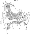
- FIG. 1 is a perspective view of a transcutaneous bone conduction device 100 in which embodiments of the present disclosure may be implemented.
- the recipient has an outer ear 101, a middle ear 102 and an inner ear 103.
- outer ear 101 comprises an auricle 105 and an ear canal 106.
- Sound waves 107 is collected by auricle 105 and channeled into ear canal 106.
- a tympanic membrane 104 Disposed across the distal end of ear canal 106 is a tympanic membrane 104 which vibrates in response to acoustic wave 107.
- This vibration is coupled to oval window or fenestra ovalis 110 through three bones of middle ear 102, collectively referred to as the ossicles 111 and comprising the malleus 112, the incus 113 and the stapes 114.
- Ossicles 111 serve to filter and amplify acoustic wave 107, causing oval window 110 to vibrate.
- Such vibration sets up waves of fluid motion within cochlea 115 which, in turn, activates hair cells lining the inside of the cochlea. Activation of the hair cells causes appropriate nerve impulses to be transferred through the spiral ganglion cells and auditory nerve 116 to the brain, where they are perceived as sound.
- FIG. 1 also illustrates the positioning of bone conduction device 100 on the recipient.
- bone conduction device 100 is secured to the skull behind outer ear 101.
- Bone conduction device 100 comprises an external component 140 that includes a sound input element (not shown) to receive sound signals.
- the sound input element may comprise, for example, a microphone, telecoil, etc.
- the sound input element may be located, for example, on or in external component 140 or on a cable or tube extending from external component 140.
- the sound input element may be subcutaneously implanted in the recipient, or positioned in the recipient's ear.
- the sound input element may also be a component that receives an electronic signal indicative of sound, such as, for example, from an external audio device.
- External component 140 also comprises a sound processor (not shown), an actuator (also not shown) and/or various other functional components, including a pressure plate 146.
- the sound input device converts received sound into electrical signals. These electrical signals are processed by the sound processor to generate control signals that cause pressure plate 146 to vibrate and deliver mechanical vibrations to internal or implantable component 150.
- a pad 154 further described below is positioned in contact with the recipient's skin 132 between the skin 132 and pressure plate 146.
- Internal or implantable component 150 comprises a bone fixture 162 such as a bone screw to secure an implantable magnetic component 152 to skull bone 136.
- bone fixture 162 is configured to osseointegrate into skull bone 136.
- Magnetic component 152 forms a magnetic coupling with magnets 156 in external component 140 sufficient to permit effective transcutaneous transfer of the mechanical vibrations to internal component 150, which are then transferred to skull bone 136.
- the vibrations from external component 140 may be transcutaneously transferred to implantable component 150 via the magnetic coupling.
- external component 150 includes a pressure plate 146 that may conform to the curvature of the recipient's skull. In such embodiments, vibrations produced by the vibrating actuator are transferred from plate 146 across the skin to implantable component 150. It should be appreciated, however, that external component 140 may take on a variety of configurations some of which do not include a pressure plate as illustrated in FIG. 1 .
- the housing of the vibrator actuator directly contacts the recipient in some embodiments, while in other embodiments external component 140 is disposed in a Behind-The-Ear (BTE) device that directly contacts the recipient's head.
- BTE Behind-The-Ear
- the portion of external component 140 that contacts the recipient for transcutaneous transfer of vibrations such as pressure plate 146, a portion of an actuator housing or a portion of a BTE housing, is referred to herein as a pressure plate.
- the exemplary transcutaneous bone conduction device illustrated in FIG. 1 has all active components, such as the actuator, located in external component 140. As such, the device illustrated in FIG. 1 is commonly referred to as a passive transcutaneous bone conduction device.
- passive transcutaneous bone conduction device 100 requires accommodation of two somewhat contradictory objectives.
- First external component 140 needs to be secured in place in contact with the recipient's scalp so that it does not slip out of position, and so that vibrations from external component 140 are effectively transmitted to internal or implantable component 150.
- Certain embodiments of pad 154 therefore, provide a balance of pressure-equalizing and vibration-transmission capacities.
- FIGS. 2 and 3 depict an exemplary embodiment of transcutaneous bone conduction device 100 including embodiments of pad 154.
- pad 154 distributes the forces exerted by pressure plate 146 substantially evenly across the entire area of contact to enhance recipient comfort and reduce the likelihood of damage to or development of sores in the recipient's skin 132.
- Pad 154 also transmits mechanical vibrations of pressure plate 146 to skin 132 so that vibrations are induced in a vibratory portion of implantable component 150.
- Embodiments of pad 154 provide both (a) conformation and low pressure characteristics; and (b) efficient vibration transmission if the material(s) forming all or a portion of pad 154 are non-Newtonian material(s).
- Non-Newtonian materials are advantageous because they provide a controllably variable balance of pressure equalization and sound transmission capacity.
- Non-Newtonian materials include, for example, Dilatant material, Rheopectic materials, and Slow recovery memory foam materials. Each of these exemplary materials is described below.
- Dilatant material Application of shear strain to these types of materials causes the viscosity to increase. In other words, these materials get harder when you apply force to them.
- An example of a dilatant material is an organosilicon made from silicone oil and boric acid.
- Rheopectic materials These materials are closely similar to dilatants. However, rheopectic materials develop higher viscosity (or get harder) when they are shaken. When shaking of these materials stops, hardness drops. Examples of rheopectic fluids include gypsum pastes and printers inks. Polymeric rheopectic materials include some urethane materials.
- Slow recovery memory foam materials including, for example, polyurethane memory foams. Viscoelastic properties make memory foams effective in distributing pressure. There are basically two types of slow recovery memory foams. Low density memory foams are pressure sensitive, while high density memory foams are heat sensitive. Viscoelastic memory foams with a variety of different density, tensile strength, elongation, porosity and other properties are available and can be used in practicing various embodiments of the disclosed technology.
- All of these materials conform slowly to improve and equalize pressure distribution while exhibiting sufficient stiffness or apparent viscosity in use to achieve efficient sound or vibration transmission from external component 140 to internal component 150.
- These materials are sufficiently soft as to substantially conform to the topologies of at least a portion of the recipient's scalp or head, and to substantially equalize pressure distribution while also stiffening in response to certain external stimulus such as, for example, vibrations.
- the material used for the pad sufficiently stiffens in the presence of mechanical vibrations to achieve efficient vibration transmission from external component 140 to internal components 150.
- Embodiments of the materials used to form pad 154 exert a force between approximately 0.4N to approximately 2.5N, via pressure plate 146, to ensure adequate retention of external component 140 on the recipient as well as to provide adequate vibration transfer to internal component 150.
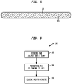
- Embodiments of pad 154 facilitate a method 180 of positioning bone conduction prosthesis 100, as illustrated in Figure 6 , in which a first step 182 involves securing pad 154 in contact with the recipient's skin, a second step 184 involves permitting pad 154 to conform to the recipient's anatomy and a third step 186 involves causing implantable component 150 to vibrate.
- Dilatant or rheopectic materials usable in alternative embodiments may be sufficiently viscous to substantially conform to a recipient's scalp or head shape. In the presence of a shear force or shaking, the viscosity of the material changes sufficiently to result in the material behaving as solids. This increases the effectiveness of the materials to transfer vibrations. Such materials, therefore, may be contained in a cover, container, bladder, film, bubble, skin or other structure 157 as illustrated in Figure 5 .
- pad 154 may be made of one or more plastic materials such as a thermoplastic.
- plastic materials such as a thermoplastic.
- Exemplary thermoplastic materials include, for example, polyvinyl chloride and polylactic acid.
- Polylactic acid or polylactide is a thermoplastic aliphatic polyester.
- thermoplastic pad 154 may be softened by the application of heat.
- pad 154 may be immersed in hot water, or the pad may be heated via convection or conduction.
- Pad 154 might then be held in position against the recipient's scalp 132 and permitted to cool and at least partially solidify while maintaining a shape that conforms to the recipient's scalp.
- some embodiments include a cover, container, bladder, film, bubble, skin or other structure 157 to contain the material when it is in a more viscous state, as is illustrated in Figure 5 .
- pad 154 includes other materials, for example, as filler for a pad structure that might include a bladder or other fluid-holding structure 157 ( Figure 5 ).
- Such materials include, for example, electro-rheological (ER) or magneto-rheological (MR) fluids.
- Electro-rheological fluids generally are suspensions of extremely fine non-conducting particles (up to 50 micrometres diameter) in an electrically insulating fluid. The apparent viscosity of these fluids changes reversibly by an order of up to 100,000 in response to an electric field.
- a magneto-rheological fluid typically consists of 20-40 percent by volume of relatively pure, 3-10 micron diameter iron particles, suspended in a carrier liquid such as mineral oil, synthetic oil, water or glycol. When subjected to a magnetic field, the fluid greatly increases its apparent viscosity, to the point of becoming a viscoelastic solid.
- Such ER and MR fluids could be controlled to have a lower viscosity while conforming to the recipient's anatomy and then controlled to have a higher viscosity when sound transmission is desired.
- Such higher apparent viscosity might be induced in the fluid only during detection of sound at a certain level so that pad 154 can re-conform to the recipient's anatomy during periods of relative silence.
- ER and MR fluids may need to be contained in a cover, container, bladder, film, bubble, skin or other structure 157 as depicted in Figure 5 .
- Pad 154 may also be a multi-layer structure having layers of different materials or of similar materials having different physical properties.
- pad 154 is a multi-layered structure comprising urethane foams.
- Pad 154 may also be coated with one or more of a variety of coatings chosen to impart one or more physical or aesthetic properties such as color, durability, impermeability or other properties.
- the contact between the recipient and pressure plate 146 may have implications for sound quality, feedback and the like and can also have implications for the appearance of device 100.
- a pad 154 may be interposed between pressure plate 146 and the recipient's skin 132 in order to equalize pressure exerted on the skin.
- Pad 154 may include a material that generally conforms over time to the contour of the recipient's skin, thereby equalizing such pressure on the skin.
- the material forming pad 154 may be soft enough to generally conform to topologies of at least a portion of the recipient's body or head at a recipient's body temperature.
- Pad 154 is formed of one or more materials selected so that the pad exhibits properties of a rigid body in response to audio-frequency vibrations. As such, embodiments of pad 154 thereby efficiently transmit such vibrations from pressure plate 142 to components 150 implanted in the recipient notwithstanding the conformational capabilities of the pad.
- pad 154 may be attached to pressure plate 146 with adhesive tape or film 158 positioned between pad 154 and pressure plate 146.
- pad 154 may be secured to pressure plate 146 by mechanical or any other means which appropriately facilitate (or at least does not unduly interfere with) transmission of vibrations between these two components.
- Adhesive 166 may also be used if desired between pad 154 and recipient's skin or scalp 132 to augment the magnetic force holding external component 140 in place or to augment a secondary material such as a non-porous film that is easy to clean or, alternatively, an additional pad.
- pad 154 can have an upper layer of adhesive 168 protected by a release film 170 that is removed before attaching pad 154 to pressure plate 146. Moreover, a lower layer of adhesive 172 suitable for recipient contact may be protected by a release film 174 that is removed before positioning external component 140 on the recipient's scalp or skin 132.
- pad 154 The appropriate shape and thickness of pad 154 will depend on the system with which it is being used, the shape and size of pressure plate 146, and numerous other considerations. Some such pads 154 may be approximately the same shape as pressure plate 146 with which the pad is used and may be approximately 0.5 to 5 millimeters thick, preferably about 1 to 2 millimeters thick, and more preferably about 1 millimeter thick.
- transcutaneous bone conduction device 100 is, as noted, a passive device due to the vibrating actuator being located externally; that is, in external component 140. It should be appreciated, however, that aspects and embodiments disclosed herein may be implemented in an active transcutaneous bone conduction device which has the vibrating actuator located in an implantable or internal component such as internal component 150. Accordingly, the scope of the claims is not limited to the embodiments described above or depicted in the drawings, and various embodiments and modifications can be made without departing from the scope of the claims below and their equivalents.
Landscapes
- Health & Medical Sciences (AREA)
- General Health & Medical Sciences (AREA)
- Otolaryngology (AREA)
- Engineering & Computer Science (AREA)
- Physics & Mathematics (AREA)
- Acoustics & Sound (AREA)
- Signal Processing (AREA)
- Neurosurgery (AREA)
- Percussion Or Vibration Massage (AREA)
- Prostheses (AREA)
- Multimedia (AREA)
- Details Of Audible-Bandwidth Transducers (AREA)
Description
- This application claims priority to
U.S. Patent Application No. 13/768,206 - This disclosure relates generally to bone conduction devices, and more particularly, to transcutaneous bone conduction devices.
- Hearing loss, which may be due to many different causes, is generally of two types: conductive and sensorineural. Sensorineural hearing loss is due to the absence or destruction of the hair cells in the cochlea that transduce sound signals into nerve impulses. Various hearing prostheses are commercially available to provide individuals suffering from sensorineural hearing loss with the ability to perceive sound. For example, cochlear implants include an electrode array for implantation in the cochlea to deliver electrical stimuli to the auditory nerve, thereby causing a hearing percept.
- Conductive hearing loss occurs when the normal mechanical pathways that provide sound to hair cells in the cochlea are impeded, for example, by damage to the ossicular chain or ear canal. Individuals suffering from conductive hearing loss may retain some form of residual hearing because the hair cells in the cochlea may remain undamaged.
- Individuals suffering from conductive hearing loss typically receive an acoustic hearing aid. Hearing aids rely on principles of air conduction to transmit acoustic signals to the cochlea. In particular, a hearing aid typically uses a component positioned at the recipient's auricle or ear canal which amplifies received sound. This amplified sound reaches the cochlea causing stimulation of the auditory nerve.
- In contrast to hearing aids, certain types of hearing prostheses commonly referred to as bone conduction devices convert a received sound into mechanical vibrations. The vibrations are transferred through the skull or jawbone to the cochlea causing generation of nerve impulses, which result in the perception of the received sound. Bone conduction devices may be a suitable alternative for individuals who cannot derive sufficient benefit from acoustic hearing aids, cochlear implants, etc.
- Coupling bone conduction devices to the cranium or jawbone in ways that remain functional and comfortable for the recipient is challenging because of the nature and location of forces that must be utilized and successfully managed.
- A prior art document
US2012/294466 discloses a hearing system, comprising: an adhesive element adapted to temporarily adhere to the skin of a recipient; a hearing prosthesis having a coupler; and an anchor having a first surface adapted to adhere to the adhesive element, and a fixture adapted to attach to the coupler of the hearing prosthesis. - In accordance with one aspect of this disclosure an implantable component of a prosthesis, comprising a bone fixture and one or more magnets or magnetic components disposed in a housing coupled to a bone fixture, such as an osseointegrating screw implant, is implanted in a recipient so that there is no structure penetrating the skin following post-implantation healing. An external component comprising a sound processor and a vibrator is magnetically coupled to the implanted component by means of a pressure plate. Magnets or magnetic components are disposed in the external component or pressure plate are attracted to magnets or magnetic components in the implanted component. This magnetic attraction draws the pressure plate into contact with, and thereby applies force to, the recipient's skin.
- Alternatively the pressure plate may be held in contact with the recipient's skin by a headband encircling the recipient's head or any other appropriate means for maintaining the pressure plate in its proper location.
- A pad or layer between the pressure plate and the recipient's skin that transfers force to the skin evenly while also appropriately transmitting vibrations avoids higher pressure contact points or regions to enhance recipient comfort and reduce the likelihood and incidence of pressure wounds or skin necrosis due to pressure. Such a material generally needs the capacity to conform very accurately to the "topography" of the recipient's skin in contact with the pressure plate. It is generally acceptable for such conformation to occur over a relatively significant period of time or to require a one-time process for fitting the pressure plate to the recipient. Materials suitable for use in implementing embodiments of this invention need to have some ability to transmit audio-frequency vibrations so that the hearing prosthesis can function successfully. Materials suitable for such a pad between the recipient's skin and the external component also need to facilitate securing the external component in place during a normal range of recipient activities. The materials used for the pad provide controllably variable balance of pressure equalization and vibration transmission capability. The materials can be controlled to provide balance of pressure equalization and vibration transmission capability.
- Such a pressure-equalizing layer or pad comprises at least one of: (a) a layer or layers of non-Newtonian material like dilatant material, rheopectic or slow-recovery memory foam (b) a layer of plastic material (such as a thermoplastic like polyvinyl chloride or polylactic acid) for positioning between the vibrating unit and the recipient's scalp that is softened and, while still soft, conformed to the shape of the wearer's scalp overlying the implanted prosthesis and then solidified or permitted to solidify for use between the scalp and the vibrating unit, (c) other viscoelastic materials (d) or other materials having adjustable apparent viscosity.
- In accordance with another aspect of the present disclosure a method comprising the steps of: causing the viscosity of a material to decrease thereby enabling a pad containing the material to conform to the topographies of a recipient's head and causing the viscosity of the material to increase thereby enabling the pad to effectively transfer sound vibrations to the recipient's head.
- Embodiments of the present disclosure are described below with reference to the attached drawings, in which:
-
FIG. 1 is a perspective view of an exemplary bone conduction device in which embodiments of the present disclosure may be implemented; -
FIG. 2 is an enlarged side view, partially in section, showing the exemplary bone conduction device ofFIG. 1 ; -
FIG. 3 is a further enlarged side view of the external portion of bone conduction device ofFIG. 1 ; -
FIG. 4 is an enlarged side view of another embodiment of the bone conduction pad with adhesive and release films; -
FIG. 5 is an enlarged side view, in section, of an embodiment of the pad having a cover or container; and -
FIG. 6 is a flow diagram showing an embodiment of a method for transmitting sound vibrations between a transcutaneous bone conduction system transmitter and a bone conduction fixture implanted in a recipient. - Aspects of the present disclosure are generally directed to a transcutaneous bone conduction device configured to deliver mechanical vibrations generated by an external vibrator to a recipient's cochlea via the skull to cause a hearing percept. The bone conduction device includes an implantable bone fixture adapted to be secured to the skull, and one or more magnets disposed in a housing coupled to the bone fixture. When implanted, the one or more magnets are capable of forming a magnetic coupling with the external vibrator sufficient to permit effective transfer of the mechanical vibrations to the implanted magnets, which are then transferred to the skull via the bone fixture.
-
FIG. 1 is a perspective view of a transcutaneousbone conduction device 100 in which embodiments of the present disclosure may be implemented. As shown, the recipient has anouter ear 101, amiddle ear 102 and aninner ear 103. In a fully functional human hearing anatomy,outer ear 101 comprises anauricle 105 and anear canal 106.Sound waves 107 is collected by auricle 105 and channeled intoear canal 106. Disposed across the distal end ofear canal 106 is atympanic membrane 104 which vibrates in response toacoustic wave 107. This vibration is coupled to oval window or fenestra ovalis 110 through three bones ofmiddle ear 102, collectively referred to as theossicles 111 and comprising themalleus 112, theincus 113 and thestapes 114.Ossicles 111 serve to filter and amplifyacoustic wave 107, causingoval window 110 to vibrate. Such vibration sets up waves of fluid motion withincochlea 115 which, in turn, activates hair cells lining the inside of the cochlea. Activation of the hair cells causes appropriate nerve impulses to be transferred through the spiral ganglion cells andauditory nerve 116 to the brain, where they are perceived as sound. -
FIG. 1 also illustrates the positioning ofbone conduction device 100 on the recipient. As shown,bone conduction device 100 is secured to the skull behindouter ear 101.Bone conduction device 100 comprises anexternal component 140 that includes a sound input element (not shown) to receive sound signals. The sound input element may comprise, for example, a microphone, telecoil, etc. In an exemplary embodiment, the sound input element may be located, for example, on or inexternal component 140 or on a cable or tube extending fromexternal component 140. Alternatively, the sound input element may be subcutaneously implanted in the recipient, or positioned in the recipient's ear. The sound input element may also be a component that receives an electronic signal indicative of sound, such as, for example, from an external audio device. -
External component 140 also comprises a sound processor (not shown), an actuator (also not shown) and/or various other functional components, including apressure plate 146. In operation, the sound input device converts received sound into electrical signals. These electrical signals are processed by the sound processor to generate control signals that causepressure plate 146 to vibrate and deliver mechanical vibrations to internal orimplantable component 150. - A
pad 154 further described below is positioned in contact with the recipient'sskin 132 between theskin 132 andpressure plate 146. - Internal or
implantable component 150 comprises abone fixture 162 such as a bone screw to secure an implantablemagnetic component 152 toskull bone 136. Typically,bone fixture 162 is configured to osseointegrate intoskull bone 136.Magnetic component 152 forms a magnetic coupling withmagnets 156 inexternal component 140 sufficient to permit effective transcutaneous transfer of the mechanical vibrations tointernal component 150, which are then transferred toskull bone 136. Alternatively, the vibrations fromexternal component 140 may be transcutaneously transferred toimplantable component 150 via the magnetic coupling. - In the embodiments described herein,
external component 150 includes apressure plate 146 that may conform to the curvature of the recipient's skull. In such embodiments, vibrations produced by the vibrating actuator are transferred fromplate 146 across the skin toimplantable component 150. It should be appreciated, however, thatexternal component 140 may take on a variety of configurations some of which do not include a pressure plate as illustrated inFIG. 1 . For example, the housing of the vibrator actuator directly contacts the recipient in some embodiments, while in other embodimentsexternal component 140 is disposed in a Behind-The-Ear (BTE) device that directly contacts the recipient's head. In these and other bone conduction devices, the portion ofexternal component 140 that contacts the recipient for transcutaneous transfer of vibrations such aspressure plate 146, a portion of an actuator housing or a portion of a BTE housing, is referred to herein as a pressure plate. - Because the anatomy and scalp shape vary from one recipient to another, no single plate has a contour or shape that will closely conform to every recipient. Moreover, in order to achieve sufficient retention of
external component 140 to efficiently transfer sound vibrations, adequate magnetic attraction is needed between theimplantable component 150 and theexternal component 140. Alternatively, other means such as a headband may be used to apply adequate force to holdexternal component 140 in its proper position. The attraction needed in a particular situation depends, among other things, on the weight ofexternal component 140 and the motion of the recipient. The pressure that is exerted on the recipient's skin is a result of the skin contacting area ofplate 146 and the force of attraction between the internal and external components. Excessive pressure (either localized or across the contacting surfaces) may cause soft tissue damage. Typically, for example a pressure of approximately 0.7N/cm2 is enough to cause damage to the soft tissue. In extreme cases, the soft tissue necrotizes and needs to heal beforedevice 100 can be used again. - The exemplary transcutaneous bone conduction device illustrated in
FIG. 1 has all active components, such as the actuator, located inexternal component 140. As such, the device illustrated inFIG. 1 is commonly referred to as a passive transcutaneous bone conduction device. - As is apparent from the description above, operation of passive transcutaneous
bone conduction device 100 requires accommodation of two somewhat contradictory objectives. Firstexternal component 140 needs to be secured in place in contact with the recipient's scalp so that it does not slip out of position, and so that vibrations fromexternal component 140 are effectively transmitted to internal orimplantable component 150. Certain embodiments ofpad 154, therefore, provide a balance of pressure-equalizing and vibration-transmission capacities. -
FIGS. 2 and3 depict an exemplary embodiment of transcutaneousbone conduction device 100 including embodiments ofpad 154. Preferably,pad 154 distributes the forces exerted bypressure plate 146 substantially evenly across the entire area of contact to enhance recipient comfort and reduce the likelihood of damage to or development of sores in the recipient'sskin 132.Pad 154 also transmits mechanical vibrations ofpressure plate 146 toskin 132 so that vibrations are induced in a vibratory portion ofimplantable component 150. - Conventional soft or easily deformed materials in a pad typically would facilitate even distribution of forces exerted by a
pressure plate 146; however, more rigid conventional materials typically better transmit vibrations. Embodiments ofpad 154 provide both (a) conformation and low pressure characteristics; and (b) efficient vibration transmission if the material(s) forming all or a portion ofpad 154 are non-Newtonian material(s). Non-Newtonian materials are advantageous because they provide a controllably variable balance of pressure equalization and sound transmission capacity. Non-Newtonian materials include, for example, Dilatant material, Rheopectic materials, and Slow recovery memory foam materials. Each of these exemplary materials is described below. - Dilatant material. Application of shear strain to these types of materials causes the viscosity to increase. In other words, these materials get harder when you apply force to them. An example of a dilatant material is an organosilicon made from silicone oil and boric acid.
- Rheopectic materials. These materials are closely similar to dilatants. However, rheopectic materials develop higher viscosity (or get harder) when they are shaken. When shaking of these materials stops, hardness drops. Examples of rheopectic fluids include gypsum pastes and printers inks. Polymeric rheopectic materials include some urethane materials.
- Slow recovery memory foam materials, including, for example, polyurethane memory foams. Viscoelastic properties make memory foams effective in distributing pressure. There are basically two types of slow recovery memory foams. Low density memory foams are pressure sensitive, while high density memory foams are heat sensitive. Viscoelastic memory foams with a variety of different density, tensile strength, elongation, porosity and other properties are available and can be used in practicing various embodiments of the disclosed technology.
- All of these materials conform slowly to improve and equalize pressure distribution while exhibiting sufficient stiffness or apparent viscosity in use to achieve efficient sound or vibration transmission from
external component 140 tointernal component 150. These materials are sufficiently soft as to substantially conform to the topologies of at least a portion of the recipient's scalp or head, and to substantially equalize pressure distribution while also stiffening in response to certain external stimulus such as, for example, vibrations. In one example, the material used for the pad sufficiently stiffens in the presence of mechanical vibrations to achieve efficient vibration transmission fromexternal component 140 tointernal components 150. Embodiments of the materials used to formpad 154 exert a force between approximately 0.4N to approximately 2.5N, viapressure plate 146, to ensure adequate retention ofexternal component 140 on the recipient as well as to provide adequate vibration transfer tointernal component 150. The materials used to theform pad 154 do not exert a pressure greater than 0.9N/cm2 on the recipient's skin to prevent damage of the soft tissue. More typically the pressure is no more than approximately 0.5N/cm2. Embodiments ofpad 154 facilitate amethod 180 of positioningbone conduction prosthesis 100, as illustrated inFigure 6 , in which afirst step 182 involves securingpad 154 in contact with the recipient's skin, asecond step 184 involves permittingpad 154 to conform to the recipient's anatomy and athird step 186 involves causingimplantable component 150 to vibrate. - Dilatant or rheopectic materials usable in alternative embodiments may be sufficiently viscous to substantially conform to a recipient's scalp or head shape. In the presence of a shear force or shaking, the viscosity of the material changes sufficiently to result in the material behaving as solids. This increases the effectiveness of the materials to transfer vibrations. Such materials, therefore, may be contained in a cover, container, bladder, film, bubble, skin or
other structure 157 as illustrated inFigure 5 . - In other embodiments,
pad 154 may be made of one or more plastic materials such as a thermoplastic. Exemplary thermoplastic materials include, for example, polyvinyl chloride and polylactic acid. Polylactic acid or polylactide is a thermoplastic aliphatic polyester. - Initially, or possibly before each use, the plastic material(s) of such a
thermoplastic pad 154 may be softened by the application of heat. For instance, pad 154 may be immersed in hot water, or the pad may be heated via convection or conduction.Pad 154 might then be held in position against the recipient'sscalp 132 and permitted to cool and at least partially solidify while maintaining a shape that conforms to the recipient's scalp. Depending on the viscosity of such a thermoplastic material, some embodiments include a cover, container, bladder, film, bubble, skin orother structure 157 to contain the material when it is in a more viscous state, as is illustrated inFigure 5 . - In alternative embodiments,
pad 154 includes other materials, for example, as filler for a pad structure that might include a bladder or other fluid-holding structure 157 (Figure 5 ). Such materials include, for example, electro-rheological (ER) or magneto-rheological (MR) fluids. Electro-rheological fluids generally are suspensions of extremely fine non-conducting particles (up to 50 micrometres diameter) in an electrically insulating fluid. The apparent viscosity of these fluids changes reversibly by an order of up to 100,000 in response to an electric field. - A magneto-rheological fluid typically consists of 20-40 percent by volume of relatively pure, 3-10 micron diameter iron particles, suspended in a carrier liquid such as mineral oil, synthetic oil, water or glycol. When subjected to a magnetic field, the fluid greatly increases its apparent viscosity, to the point of becoming a viscoelastic solid.
- Such ER and MR fluids could be controlled to have a lower viscosity while conforming to the recipient's anatomy and then controlled to have a higher viscosity when sound transmission is desired. Such higher apparent viscosity might be induced in the fluid only during detection of sound at a certain level so that
pad 154 can re-conform to the recipient's anatomy during periods of relative silence. As withother pad 154 materials that exhibit low viscosity at least some of the time, ER and MR fluids may need to be contained in a cover, container, bladder, film, bubble, skin orother structure 157 as depicted inFigure 5 . -
Pad 154 may also be a multi-layer structure having layers of different materials or of similar materials having different physical properties. For example, in one embodiment,pad 154 is a multi-layered structure comprising urethane foams.Pad 154 may also be coated with one or more of a variety of coatings chosen to impart one or more physical or aesthetic properties such as color, durability, impermeability or other properties. - Furthermore, the contact between the recipient and
pressure plate 146 may have implications for sound quality, feedback and the like and can also have implications for the appearance ofdevice 100. - As illustrated in
Figure 2 , apad 154 may be interposed betweenpressure plate 146 and the recipient'sskin 132 in order to equalize pressure exerted on the skin.Pad 154 may include a material that generally conforms over time to the contour of the recipient's skin, thereby equalizing such pressure on the skin. In one embodiment, thematerial forming pad 154 may be soft enough to generally conform to topologies of at least a portion of the recipient's body or head at a recipient's body temperature.Pad 154 is formed of one or more materials selected so that the pad exhibits properties of a rigid body in response to audio-frequency vibrations. As such, embodiments ofpad 154 thereby efficiently transmit such vibrations from pressure plate 142 tocomponents 150 implanted in the recipient notwithstanding the conformational capabilities of the pad. - Referring to
Figure 3 ,pad 154 may be attached topressure plate 146 with adhesive tape orfilm 158 positioned betweenpad 154 andpressure plate 146. Alternatively, pad 154 may be secured topressure plate 146 by mechanical or any other means which appropriately facilitate (or at least does not unduly interfere with) transmission of vibrations between these two components. - Adhesive 166 may also be used if desired between
pad 154 and recipient's skin orscalp 132 to augment the magnetic force holdingexternal component 140 in place or to augment a secondary material such as a non-porous film that is easy to clean or, alternatively, an additional pad. - As is illustrated in
Figure 4 , pad 154 can have an upper layer of adhesive 168 protected by arelease film 170 that is removed before attachingpad 154 topressure plate 146. Moreover, a lower layer of adhesive 172 suitable for recipient contact may be protected by arelease film 174 that is removed before positioningexternal component 140 on the recipient's scalp orskin 132. - The appropriate shape and thickness of
pad 154 will depend on the system with which it is being used, the shape and size ofpressure plate 146, and numerous other considerations. Somesuch pads 154 may be approximately the same shape aspressure plate 146 with which the pad is used and may be approximately 0.5 to 5 millimeters thick, preferably about 1 to 2 millimeters thick, and more preferably about 1 millimeter thick. - While various embodiments of the present disclosure have been described above, it should be understood that they have been presented by way of example only, and not limitation. It will be apparent to persons skilled in the relevant art that various changes in form and detail can be made therein without departing from the scope of the teachings of this disclosure. Thus, the scope of the present disclosure should not be limited by any of the above-described exemplary embodiments, but should be defined only in accordance with the following claims and their equivalents.
- Different arrangements of the components depicted in the drawings or described above, as well as components and steps not shown or described are possible. Similarly, some features and sub-combinations are useful and may be employed without reference to other features and sub-combinations. Embodiments have been described for illustrative and not restrictive purposes, and alternative embodiments will become apparent to readers of this patent. For example, transcutaneous
bone conduction device 100 is, as noted, a passive device due to the vibrating actuator being located externally; that is, inexternal component 140. It should be appreciated, however, that aspects and embodiments disclosed herein may be implemented in an active transcutaneous bone conduction device which has the vibrating actuator located in an implantable or internal component such asinternal component 150. Accordingly, the scope of the claims is not limited to the embodiments described above or depicted in the drawings, and various embodiments and modifications can be made without departing from the scope of the claims below and their equivalents.
Claims (15)
- A pad (154) for interposition between a recipient's head and a transcutaneous bone conduction device pressure plate (146), the pad (154) comprising a material providing a controllably variable balance of pressure-equalization and vibration-transmission capability,
characterized in that
the material comprises at least one of:non-Newtonian material having capacity to conform slowly to the contour of the recipient's head,non-Newtonian material having capacity to transmit audio frequency vibrations,dilatant material,rheopectic material,slow-recovery memory foam,low density, pressure sensitive foam,high density, heat sensitive foam,viscoelastic material, andthermo-softening plastic. - The pad (154) of claim 1, wherein the dilatant material comprises an organosilicon.
- The pad (154) of claim 1, wherein the rheopectic material comprises polymeric material.
- The pad (154) of claim 1, wherein the viscoelastic material exhibits a viscosity of between approximately 100 and 1 x 10¹⁰ centipoise.
- The pad (154) of claim 1, wherein the thermo-softening plastic material can be softened by heating it above human body temperature and formed to the recipient's anatomy by holding the material in place against the recipient's scalp proximate the subcutaneous components until it cools sufficiently to maintain its shape.
- The pad (154) of any one of the claims 1 - 5, wherein the pad is configured to be fixed to the transcutaneous bone conduction device pressure plate with an adhesive.
- The pad (154) of any one of the claims 1 - 6, wherein the pad comprises a non-Newtonian material.
- The pad (154) of any one of the claims 1 - 7, wherein the pad comprises a dilatant material.
- The pad (154) of any one of the claims 1 - 7, wherein the pad comprises a rheopectic material.
- The pad (154) of any one of the claims 1 - 7, wherein the pad comprises a memory foam.
- A transcutaneous bone conduction system (100) comprising:an external component (140); anda conformable pad (154) as claimed in one of the claims 1 - 10 for positioning between a recipient's scalp and the external component.
- The system (100) of claim 11, wherein the external component (140) comprises a vibrator and a pressure plate (146).
- A method (180) of positioning a bone conduction prosthesis, comprising:a first step (182) of securing a pad (154) according to claim 1 in contact with the recipient's skin,a second step (184) of permitting the pad (154) to conform to the recipient's anatomy by causing the viscosity of a material to decrease thereby enabling a pad containing the material to conform to the topographies of a recipient's head; anda third step (186) of causing the pad (154) to vibrate by causing the viscosity of the material to increase thereby enabling the pad to effectively transfer sound vibrations to the recipient's head.
- The method of claim 13, wherein causing the viscosity of the material to decrease comprises:
adjusting at least one of a group of external stimuli consisting of: temperature, an electric field, a magnetic field, mechanical stress, and shear stress. - The method of claim 13, wherein causing the viscosity of the material to increase comprises:
adjusting at least one of a group of external stimuli consisting of: temperature, an electric field, a magnetic field, mechanical stress, and shear stress.
Applications Claiming Priority (2)
| Application Number | Priority Date | Filing Date | Title |
|---|---|---|---|
| US13/768,206 US11095994B2 (en) | 2013-02-15 | 2013-02-15 | Conformable pad bone conduction device |
| PCT/IB2014/058927 WO2014125417A1 (en) | 2013-02-15 | 2014-02-11 | Conformable pad bone conduction device |
Publications (3)
| Publication Number | Publication Date |
|---|---|
| EP2888891A1 EP2888891A1 (en) | 2015-07-01 |
| EP2888891A4 EP2888891A4 (en) | 2016-04-27 |
| EP2888891B1 true EP2888891B1 (en) | 2019-04-17 |
Family
ID=51351174
Family Applications (1)
| Application Number | Title | Priority Date | Filing Date |
|---|---|---|---|
| EP14751228.9A Active EP2888891B1 (en) | 2013-02-15 | 2014-02-11 | Conformable pad bone conduction device |
Country Status (6)
| Country | Link |
|---|---|
| US (1) | US11095994B2 (en) |
| EP (1) | EP2888891B1 (en) |
| JP (1) | JP2016512978A (en) |
| KR (1) | KR20150117636A (en) |
| CN (1) | CN104813681B (en) |
| WO (1) | WO2014125417A1 (en) |
Families Citing this family (25)
| Publication number | Priority date | Publication date | Assignee | Title |
|---|---|---|---|---|
| US9258656B2 (en) * | 2011-12-09 | 2016-02-09 | Sophono, Inc. | Sound acquisition and analysis systems, devices and components for magnetic hearing aids |
| US9736601B2 (en) | 2012-07-16 | 2017-08-15 | Sophono, Inc. | Adjustable magnetic systems, devices, components and methods for bone conduction hearing aids |
| EP3031219A4 (en) * | 2013-08-09 | 2017-03-29 | MED-EL Elektromedizinische Geräte GmbH | Bone conduction hearing aid system |
| WO2016073167A2 (en) | 2014-11-06 | 2016-05-12 | Otorix Usa Inc. | Bone conduction hearing aid system |
| CN108353237B (en) * | 2015-10-30 | 2022-01-04 | 科利耳有限公司 | Implantable stimulation assembly |
| US10009698B2 (en) * | 2015-12-16 | 2018-06-26 | Cochlear Limited | Bone conduction device having magnets integrated with housing |
| US9967685B2 (en) * | 2015-12-16 | 2018-05-08 | Cochlear Limited | Bone conduction skin interface |
| CN106208808B (en) * | 2016-07-18 | 2018-01-02 | 辽宁工程技术大学 | A kind of noise power generator and method based on the conduction of people's otica chain type |
| DE112017003844B4 (en) * | 2016-08-01 | 2025-01-02 | Siegert Med GmbH | Device for patient-friendly coupling to hearing aids |
| US10542351B2 (en) * | 2016-09-22 | 2020-01-21 | Cochlear Limited | Coupling apparatuses for transcutaneous bone conduction devices |
| US10897677B2 (en) * | 2017-03-24 | 2021-01-19 | Cochlear Limited | Shock and impact management of an implantable device during non use |
| US10747026B1 (en) | 2017-03-28 | 2020-08-18 | Amazon Technologies, Inc. | Ergonomic spacer for head-mounted wearable device |
| US10659868B1 (en) * | 2017-03-28 | 2020-05-19 | Amazon Technologies, Inc. | Field replaceable spacer for head-mounted wearable device |
| EP3404933A1 (en) | 2017-05-15 | 2018-11-21 | Oticon Medical A/S | A hearing aid for placement on head of a user |
| US11223912B2 (en) | 2017-07-21 | 2022-01-11 | Cochlear Limited | Impact and resonance management |
| CN108543165B (en) * | 2018-02-27 | 2021-06-18 | 宁波胜杰康生物科技有限公司 | Carrier-based muscle function auxiliary device |
| CN110538002B (en) * | 2019-08-29 | 2022-02-01 | 中国医学科学院北京协和医院 | Artificial tympanic cavity |
| US20230370793A1 (en) * | 2020-10-01 | 2023-11-16 | Cochlear Limited | Active implant with percutaneous abutment |
| CN112291686B (en) * | 2020-10-29 | 2022-04-01 | 维沃移动通信有限公司 | Wearable device |
| RU2760398C1 (en) * | 2020-11-23 | 2021-11-24 | федеральное государственное бюджетное образовательное учреждение высшего образования "Московский государственный медико-стоматологический университет имени А.И. Евдокимова" Министерства здравоохранения Российской Федерации (ФГБОУ ВО МГМСУ им. А.И. Евдокимова Минздрава России) | Bionic ear prosthesis |
| CN116803101A (en) * | 2021-04-28 | 2023-09-22 | 深圳市韶音科技有限公司 | a kind of earphone |
| WO2023026123A1 (en) * | 2021-08-23 | 2023-03-02 | Cochlear Limited | Coupler for bone conduction hearing prosthesis |
| US20250203301A1 (en) * | 2022-03-03 | 2025-06-19 | Cochlear Limited | Advanced passive integrity management of an implantable device |
| CN119183390A (en) * | 2022-04-25 | 2024-12-24 | 科利耳有限公司 | External portion of a medical implant having a compliant skin contacting surface |
| US12348919B2 (en) * | 2023-04-13 | 2025-07-01 | Harman International Industries, Incorporated | Insert for headphone measurements on a head shaped fixture |
Family Cites Families (64)
| Publication number | Priority date | Publication date | Assignee | Title |
|---|---|---|---|---|
| US2470933A (en) * | 1944-06-05 | 1949-05-24 | Zenith Radio Corp | Flexible-surfaced bone conduction hearing aid unit |
| US2756016A (en) * | 1952-12-01 | 1956-07-24 | Lord Mfg Co | Shock isolator |
| US2859033A (en) * | 1956-06-27 | 1958-11-04 | Hughes Aircraft Co | Constant force applying mechanism |
| US3350344A (en) * | 1963-09-18 | 1967-10-31 | Gen Electric | Organosilicon compositions |
| US3382511A (en) * | 1967-01-13 | 1968-05-14 | William T. Brooks | Safety cushion |
| US3881570A (en) * | 1973-08-06 | 1975-05-06 | Marion Health And Safety Inc | Self-fitting hearing protector |
| US4195151A (en) * | 1976-11-22 | 1980-03-25 | Union Carbide Corporation | Phenol-aldehyde-amine resin/glycol curative compositions |
| US4298383A (en) * | 1979-06-25 | 1981-11-03 | National-Standard Company | Low viscosity composition for forming shaped bodies |
| US5573088A (en) * | 1994-05-10 | 1996-11-12 | Daniels; John J. | Controllable resistance device and force dampener, and vehicle utilizing the same |
| US5483027A (en) * | 1994-08-24 | 1996-01-09 | Krause; Ward B. | Earplug with form-fitting fluid chambers |
| DE19541882A1 (en) | 1995-11-08 | 1997-05-15 | Andreas Landwehr | Device for transmitting sound signals as mechanical vibrations on to the cranial bones of the hard of hearing |
| JP3207158B2 (en) * | 1998-05-11 | 2001-09-10 | 株式会社テムコジャパン | Headset with bone-conducting speaker and microphone |
| WO2000046303A1 (en) * | 1999-02-05 | 2000-08-10 | Extrude Hone Corporation | Smart padding system utilizing an energy absorbent medium and articles abtainable therefrom |
| JP2001029509A (en) | 1999-07-16 | 2001-02-06 | Manabu Matsumoto | Goggle |
| AU6687401A (en) * | 2000-06-14 | 2001-12-24 | Inc American Healthcare Produc | Heating pad systems, such as for patient warming applications |
| AU2000270392A1 (en) | 2000-09-01 | 2002-03-13 | Dowumi Corporation | Bone conduction vibrator |
| EP1195417B1 (en) * | 2000-10-05 | 2009-10-14 | Evonik Degussa GmbH | Silicone-organic nanocapsules |
| US20060089721A1 (en) * | 2001-01-17 | 2006-04-27 | Muhanna Nabil L | Intervertebral disc prosthesis and methods of implantation |
| JP3532535B2 (en) * | 2001-05-31 | 2004-05-31 | 株式会社テムコジャパン | Handset device |
| EP1489934B1 (en) * | 2001-09-13 | 2010-05-26 | Daniel James Plant | Flexible energy absorbing material and methods of manufacture thereof |
| JP2003322612A (en) | 2002-04-30 | 2003-11-14 | Communication Research Laboratory | Brain-activity measuring apparatus and head mounting implement for brain-activity measurement |
| WO2004030572A2 (en) | 2002-10-02 | 2004-04-15 | Otologics Llc | Retention apparatus for an external portion of a semi-implantable hearing aid |
| JP4190988B2 (en) | 2003-09-12 | 2008-12-03 | Necトーキン株式会社 | Ear-mounted sound information transmitter |
| WO2005072168A2 (en) * | 2004-01-20 | 2005-08-11 | Sound Techniques Systems Llc | Method and apparatus for improving hearing in patients suffering from hearing loss |
| DE202004006117U1 (en) | 2004-04-15 | 2004-07-08 | Siegert, Ralf, Prof. Dr. Dr.med. | Bone phone/vibrator device for patients with severe middle-ear afflictions, has a magnetic probe-to-specimen contact |
| JP2005328125A (en) | 2004-05-12 | 2005-11-24 | Nec Tokin Corp | Earphone |
| JP2006197257A (en) * | 2005-01-13 | 2006-07-27 | Toshiba Corp | Bone conduction speaker built-in pillow |
| WO2007011846A2 (en) | 2005-07-18 | 2007-01-25 | Soundquest, Inc. | In-ear auditory device and methods of using same |
| US20070053536A1 (en) * | 2005-08-24 | 2007-03-08 | Patrik Westerkull | Hearing aid system |
| KR20070035376A (en) | 2005-09-27 | 2007-03-30 | 박의봉 | Bone conduction speakers |
| US7917403B2 (en) * | 2005-11-21 | 2011-03-29 | Nightgear Llc | Seating accessory |
| US7966937B1 (en) * | 2006-07-01 | 2011-06-28 | Jason Stewart Jackson | Non-newtonian projectile |
| WO2008017933A1 (en) * | 2006-08-07 | 2008-02-14 | Dynea Oy | Stable aqueous novolac dispersion |
| US7821973B2 (en) * | 2006-10-24 | 2010-10-26 | Hewlett-Packard Development Company, L.P. | Sharing of host bus adapter context |
| GB2445539A (en) * | 2006-12-29 | 2008-07-16 | Ardana Bioscience Ltd | Bigel composition |
| JP4401396B2 (en) | 2007-01-16 | 2010-01-20 | 株式会社エヌ・ティ・ティ・ドコモ | Sound output device |
| GB0704125D0 (en) * | 2007-03-03 | 2007-04-11 | Univ Dundee | Ossicular replacement prosthesis |
| CN101315769A (en) * | 2007-05-31 | 2008-12-03 | 新兴盛科技股份有限公司 | Face bone conduction sound transmission device with buffer device |
| US8795172B2 (en) * | 2007-12-07 | 2014-08-05 | Sonitus Medical, Inc. | Systems and methods to provide two-way communications |
| DK2083582T3 (en) | 2008-01-28 | 2013-11-11 | Oticon Medical As | Bone conductive hearing aid with connection |
| US8363871B2 (en) | 2008-03-31 | 2013-01-29 | Cochlear Limited | Alternative mass arrangements for bone conduction devices |
| US8107648B2 (en) | 2008-06-05 | 2012-01-31 | Cosmogear Co., Ltd. | Bone conduction earphone |
| US7766016B2 (en) * | 2008-06-13 | 2010-08-03 | Anthony J. Orrico, Llc | Anti-snoring device |
| JP5177755B2 (en) * | 2008-12-18 | 2013-04-10 | 竹本油脂株式会社 | Dilatancy composition |
| US20120080039A1 (en) | 2009-03-15 | 2012-04-05 | Sophono, Inc. | Aid for shimming magnetic discs |
| KR101091847B1 (en) * | 2009-05-22 | 2011-12-12 | 한경희 | mask pack for vibrating massage |
| JP2011087142A (en) | 2009-10-15 | 2011-04-28 | Prefectural Univ Of Hiroshima | Stick type bone conduction hearing aid |
| US20120253105A1 (en) * | 2009-10-21 | 2012-10-04 | Woodwelding Ag | Method of anchoring an acoustic element in a bone of the craniomaxillofacial region and acoustic element |
| JP5473640B2 (en) | 2010-02-01 | 2014-04-16 | 株式会社オトデザイナーズ | Speaker device |
| US8376967B2 (en) * | 2010-04-13 | 2013-02-19 | Audiodontics, Llc | System and method for measuring and recording skull vibration in situ |
| GB201014510D0 (en) * | 2010-09-01 | 2010-10-13 | Qinetiq Ltd | Improvements in fibre optic cables for distributed sensing |
| US9042996B2 (en) | 2011-03-10 | 2015-05-26 | Cochlear Limited | Wireless communications in medical devices |
| US20120294466A1 (en) * | 2011-05-18 | 2012-11-22 | Stefan Kristo | Temporary anchor for a hearing prosthesis |
| US10419861B2 (en) | 2011-05-24 | 2019-09-17 | Cochlear Limited | Convertibility of a bone conduction device |
| US8787608B2 (en) * | 2011-05-24 | 2014-07-22 | Cochlear Limited | Vibration isolation in a bone conduction device |
| JP6096190B2 (en) * | 2011-08-16 | 2017-03-15 | シンセス・ゲーエムベーハーSynthes GmbH | Thermoplastic multilayer article |
| US9736601B2 (en) * | 2012-07-16 | 2017-08-15 | Sophono, Inc. | Adjustable magnetic systems, devices, components and methods for bone conduction hearing aids |
| US9031274B2 (en) | 2012-09-06 | 2015-05-12 | Sophono, Inc. | Adhesive bone conduction hearing device |
| US9022917B2 (en) * | 2012-07-16 | 2015-05-05 | Sophono, Inc. | Magnetic spacer systems, devices, components and methods for bone conduction hearing aids |
| US9526810B2 (en) | 2011-12-09 | 2016-12-27 | Sophono, Inc. | Systems, devices, components and methods for improved acoustic coupling between a bone conduction hearing device and a patient's head or skull |
| US20130169513A1 (en) * | 2012-01-04 | 2013-07-04 | Google Inc. | Wearable computing device |
| US8891795B2 (en) | 2012-01-31 | 2014-11-18 | Cochlear Limited | Transcutaneous bone conduction device vibrator having movable magnetic mass |
| US20130281764A1 (en) | 2012-04-19 | 2013-10-24 | Göran Björn | Transcutaneous bone conduction device |
| US9516434B2 (en) | 2013-05-09 | 2016-12-06 | Cochlear Limited | Medical device coupling arrangement |
-
2013
- 2013-02-15 US US13/768,206 patent/US11095994B2/en active Active
-
2014
- 2014-02-11 JP JP2015557545A patent/JP2016512978A/en active Pending
- 2014-02-11 KR KR1020157014447A patent/KR20150117636A/en not_active Withdrawn
- 2014-02-11 WO PCT/IB2014/058927 patent/WO2014125417A1/en not_active Ceased
- 2014-02-11 CN CN201480003216.1A patent/CN104813681B/en active Active
- 2014-02-11 EP EP14751228.9A patent/EP2888891B1/en active Active
Non-Patent Citations (1)
| Title |
|---|
| None * |
Also Published As
| Publication number | Publication date |
|---|---|
| CN104813681B (en) | 2020-01-21 |
| US20140233765A1 (en) | 2014-08-21 |
| EP2888891A1 (en) | 2015-07-01 |
| CN104813681A (en) | 2015-07-29 |
| US11095994B2 (en) | 2021-08-17 |
| EP2888891A4 (en) | 2016-04-27 |
| WO2014125417A1 (en) | 2014-08-21 |
| KR20150117636A (en) | 2015-10-20 |
| JP2016512978A (en) | 2016-05-12 |
Similar Documents
| Publication | Publication Date | Title |
|---|---|---|
| US11095994B2 (en) | Conformable pad bone conduction device | |
| US9942672B2 (en) | Devices for enhancing transmissions of stimuli in auditory prostheses | |
| US10321247B2 (en) | External component with inductance and mechanical vibratory functionality | |
| CN105188608B (en) | Medical Devices coupled arrangement | |
| CN107771095B (en) | Magnet ManagementMRI Compatibility | |
| US6629923B2 (en) | At least partially implantable hearing system with direct mechanical stimulation of a lymphatic space of the inner ear | |
| US11412334B2 (en) | Contralateral sound capture with respect to stimulation energy source | |
| US20120294466A1 (en) | Temporary anchor for a hearing prosthesis | |
| CN106170990A (en) | percutaneous vibrating conductor | |
| CN110637467A (en) | Implant magnet support | |
| US11252514B2 (en) | Coupling apparatuses for transcutaneous bone conduction devices | |
| US20210211818A1 (en) | Microphone placement | |
| US10284973B2 (en) | Wearable band for facilitating hearing | |
| US20240223974A1 (en) | Dynamic fitting for device worn on recipient's body | |
| US10798502B2 (en) | Implantable transducer system | |
| US10812919B2 (en) | Filtering well-defined feedback from a hard-coupled vibrating transducer | |
| US11496845B1 (en) | Horizontal abutment extender | |
| US20260046572A1 (en) | Transducer failsafe for medical implant | |
| EP2974380B1 (en) | Filtering well-defined feedback from a hard-coupled vibrating transducer | |
| WO2026038089A1 (en) | Electrically insulated fixation element | |
| WO2026058104A1 (en) | Implantable apparatus with electrically insulated coupler |
Legal Events
| Date | Code | Title | Description |
|---|---|---|---|
| PUAI | Public reference made under article 153(3) epc to a published international application that has entered the european phase |
Free format text: ORIGINAL CODE: 0009012 |
|
| 17P | Request for examination filed |
Effective date: 20150324 |
|
| AK | Designated contracting states |
Kind code of ref document: A1 Designated state(s): AL AT BE BG CH CY CZ DE DK EE ES FI FR GB GR HR HU IE IS IT LI LT LU LV MC MK MT NL NO PL PT RO RS SE SI SK SM TR |
|
| AX | Request for extension of the european patent |
Extension state: BA ME |
|
| RA4 | Supplementary search report drawn up and despatched (corrected) |
Effective date: 20160329 |
|
| RIC1 | Information provided on ipc code assigned before grant |
Ipc: H04R 25/00 20060101AFI20160321BHEP Ipc: A61F 2/18 20060101ALI20160321BHEP |
|
| DAX | Request for extension of the european patent (deleted) | ||
| STAA | Information on the status of an ep patent application or granted ep patent |
Free format text: STATUS: REQUEST FOR EXAMINATION WAS MADE |
|
| R17P | Request for examination filed (corrected) |
Effective date: 20150324 |
|
| GRAP | Despatch of communication of intention to grant a patent |
Free format text: ORIGINAL CODE: EPIDOSNIGR1 |
|
| STAA | Information on the status of an ep patent application or granted ep patent |
Free format text: STATUS: GRANT OF PATENT IS INTENDED |
|
| INTG | Intention to grant announced |
Effective date: 20181106 |
|
| GRAS | Grant fee paid |
Free format text: ORIGINAL CODE: EPIDOSNIGR3 |
|
| GRAA | (expected) grant |
Free format text: ORIGINAL CODE: 0009210 |
|
| STAA | Information on the status of an ep patent application or granted ep patent |
Free format text: STATUS: THE PATENT HAS BEEN GRANTED |
|
| AK | Designated contracting states |
Kind code of ref document: B1 Designated state(s): AL AT BE BG CH CY CZ DE DK EE ES FI FR GB GR HR HU IE IS IT LI LT LU LV MC MK MT NL NO PL PT RO RS SE SI SK SM TR |
|
| REG | Reference to a national code |
Ref country code: GB Ref legal event code: FG4D |
|
| REG | Reference to a national code |
Ref country code: CH Ref legal event code: EP |
|
| REG | Reference to a national code |
Ref country code: DE Ref legal event code: R096 Ref document number: 602014044918 Country of ref document: DE |
|
| REG | Reference to a national code |
Ref country code: AT Ref legal event code: REF Ref document number: 1122849 Country of ref document: AT Kind code of ref document: T Effective date: 20190515 Ref country code: IE Ref legal event code: FG4D |
|
| REG | Reference to a national code |
Ref country code: NL Ref legal event code: MP Effective date: 20190417 |
|
| REG | Reference to a national code |
Ref country code: LT Ref legal event code: MG4D |
|
| PG25 | Lapsed in a contracting state [announced via postgrant information from national office to epo] |
Ref country code: NL Free format text: LAPSE BECAUSE OF FAILURE TO SUBMIT A TRANSLATION OF THE DESCRIPTION OR TO PAY THE FEE WITHIN THE PRESCRIBED TIME-LIMIT Effective date: 20190417 |
|
| PG25 | Lapsed in a contracting state [announced via postgrant information from national office to epo] |
Ref country code: ES Free format text: LAPSE BECAUSE OF FAILURE TO SUBMIT A TRANSLATION OF THE DESCRIPTION OR TO PAY THE FEE WITHIN THE PRESCRIBED TIME-LIMIT Effective date: 20190417 Ref country code: LT Free format text: LAPSE BECAUSE OF FAILURE TO SUBMIT A TRANSLATION OF THE DESCRIPTION OR TO PAY THE FEE WITHIN THE PRESCRIBED TIME-LIMIT Effective date: 20190417 Ref country code: SE Free format text: LAPSE BECAUSE OF FAILURE TO SUBMIT A TRANSLATION OF THE DESCRIPTION OR TO PAY THE FEE WITHIN THE PRESCRIBED TIME-LIMIT Effective date: 20190417 Ref country code: HR Free format text: LAPSE BECAUSE OF FAILURE TO SUBMIT A TRANSLATION OF THE DESCRIPTION OR TO PAY THE FEE WITHIN THE PRESCRIBED TIME-LIMIT Effective date: 20190417 Ref country code: AL Free format text: LAPSE BECAUSE OF FAILURE TO SUBMIT A TRANSLATION OF THE DESCRIPTION OR TO PAY THE FEE WITHIN THE PRESCRIBED TIME-LIMIT Effective date: 20190417 Ref country code: NO Free format text: LAPSE BECAUSE OF FAILURE TO SUBMIT A TRANSLATION OF THE DESCRIPTION OR TO PAY THE FEE WITHIN THE PRESCRIBED TIME-LIMIT Effective date: 20190717 Ref country code: PT Free format text: LAPSE BECAUSE OF FAILURE TO SUBMIT A TRANSLATION OF THE DESCRIPTION OR TO PAY THE FEE WITHIN THE PRESCRIBED TIME-LIMIT Effective date: 20190817 Ref country code: FI Free format text: LAPSE BECAUSE OF FAILURE TO SUBMIT A TRANSLATION OF THE DESCRIPTION OR TO PAY THE FEE WITHIN THE PRESCRIBED TIME-LIMIT Effective date: 20190417 |
|
| PG25 | Lapsed in a contracting state [announced via postgrant information from national office to epo] |
Ref country code: LV Free format text: LAPSE BECAUSE OF FAILURE TO SUBMIT A TRANSLATION OF THE DESCRIPTION OR TO PAY THE FEE WITHIN THE PRESCRIBED TIME-LIMIT Effective date: 20190417 Ref country code: PL Free format text: LAPSE BECAUSE OF FAILURE TO SUBMIT A TRANSLATION OF THE DESCRIPTION OR TO PAY THE FEE WITHIN THE PRESCRIBED TIME-LIMIT Effective date: 20190417 Ref country code: GR Free format text: LAPSE BECAUSE OF FAILURE TO SUBMIT A TRANSLATION OF THE DESCRIPTION OR TO PAY THE FEE WITHIN THE PRESCRIBED TIME-LIMIT Effective date: 20190718 Ref country code: BG Free format text: LAPSE BECAUSE OF FAILURE TO SUBMIT A TRANSLATION OF THE DESCRIPTION OR TO PAY THE FEE WITHIN THE PRESCRIBED TIME-LIMIT Effective date: 20190717 Ref country code: RS Free format text: LAPSE BECAUSE OF FAILURE TO SUBMIT A TRANSLATION OF THE DESCRIPTION OR TO PAY THE FEE WITHIN THE PRESCRIBED TIME-LIMIT Effective date: 20190417 |
|
| REG | Reference to a national code |
Ref country code: AT Ref legal event code: MK05 Ref document number: 1122849 Country of ref document: AT Kind code of ref document: T Effective date: 20190417 |
|
| PG25 | Lapsed in a contracting state [announced via postgrant information from national office to epo] |
Ref country code: IS Free format text: LAPSE BECAUSE OF FAILURE TO SUBMIT A TRANSLATION OF THE DESCRIPTION OR TO PAY THE FEE WITHIN THE PRESCRIBED TIME-LIMIT Effective date: 20190817 |
|
| REG | Reference to a national code |
Ref country code: DE Ref legal event code: R097 Ref document number: 602014044918 Country of ref document: DE |
|
| PG25 | Lapsed in a contracting state [announced via postgrant information from national office to epo] |
Ref country code: CZ Free format text: LAPSE BECAUSE OF FAILURE TO SUBMIT A TRANSLATION OF THE DESCRIPTION OR TO PAY THE FEE WITHIN THE PRESCRIBED TIME-LIMIT Effective date: 20190417 Ref country code: SK Free format text: LAPSE BECAUSE OF FAILURE TO SUBMIT A TRANSLATION OF THE DESCRIPTION OR TO PAY THE FEE WITHIN THE PRESCRIBED TIME-LIMIT Effective date: 20190417 Ref country code: RO Free format text: LAPSE BECAUSE OF FAILURE TO SUBMIT A TRANSLATION OF THE DESCRIPTION OR TO PAY THE FEE WITHIN THE PRESCRIBED TIME-LIMIT Effective date: 20190417 Ref country code: DK Free format text: LAPSE BECAUSE OF FAILURE TO SUBMIT A TRANSLATION OF THE DESCRIPTION OR TO PAY THE FEE WITHIN THE PRESCRIBED TIME-LIMIT Effective date: 20190417 Ref country code: AT Free format text: LAPSE BECAUSE OF FAILURE TO SUBMIT A TRANSLATION OF THE DESCRIPTION OR TO PAY THE FEE WITHIN THE PRESCRIBED TIME-LIMIT Effective date: 20190417 Ref country code: EE Free format text: LAPSE BECAUSE OF FAILURE TO SUBMIT A TRANSLATION OF THE DESCRIPTION OR TO PAY THE FEE WITHIN THE PRESCRIBED TIME-LIMIT Effective date: 20190417 |
|
| PLBE | No opposition filed within time limit |
Free format text: ORIGINAL CODE: 0009261 |
|
| STAA | Information on the status of an ep patent application or granted ep patent |
Free format text: STATUS: NO OPPOSITION FILED WITHIN TIME LIMIT |
|
| PG25 | Lapsed in a contracting state [announced via postgrant information from national office to epo] |
Ref country code: IT Free format text: LAPSE BECAUSE OF FAILURE TO SUBMIT A TRANSLATION OF THE DESCRIPTION OR TO PAY THE FEE WITHIN THE PRESCRIBED TIME-LIMIT Effective date: 20190417 Ref country code: SM Free format text: LAPSE BECAUSE OF FAILURE TO SUBMIT A TRANSLATION OF THE DESCRIPTION OR TO PAY THE FEE WITHIN THE PRESCRIBED TIME-LIMIT Effective date: 20190417 |
|
| 26N | No opposition filed |
Effective date: 20200120 |
|
| PG25 | Lapsed in a contracting state [announced via postgrant information from national office to epo] |
Ref country code: TR Free format text: LAPSE BECAUSE OF FAILURE TO SUBMIT A TRANSLATION OF THE DESCRIPTION OR TO PAY THE FEE WITHIN THE PRESCRIBED TIME-LIMIT Effective date: 20190417 |
|
| PG25 | Lapsed in a contracting state [announced via postgrant information from national office to epo] |
Ref country code: SI Free format text: LAPSE BECAUSE OF FAILURE TO SUBMIT A TRANSLATION OF THE DESCRIPTION OR TO PAY THE FEE WITHIN THE PRESCRIBED TIME-LIMIT Effective date: 20190417 |
|
| REG | Reference to a national code |
Ref country code: CH Ref legal event code: PL |
|
| GBPC | Gb: european patent ceased through non-payment of renewal fee |
Effective date: 20200211 |
|
| REG | Reference to a national code |
Ref country code: BE Ref legal event code: MM Effective date: 20200229 |
|
| PG25 | Lapsed in a contracting state [announced via postgrant information from national office to epo] |
Ref country code: LU Free format text: LAPSE BECAUSE OF NON-PAYMENT OF DUE FEES Effective date: 20200211 Ref country code: MC Free format text: LAPSE BECAUSE OF FAILURE TO SUBMIT A TRANSLATION OF THE DESCRIPTION OR TO PAY THE FEE WITHIN THE PRESCRIBED TIME-LIMIT Effective date: 20190417 |
|
| PG25 | Lapsed in a contracting state [announced via postgrant information from national office to epo] |
Ref country code: LI Free format text: LAPSE BECAUSE OF NON-PAYMENT OF DUE FEES Effective date: 20200229 Ref country code: CH Free format text: LAPSE BECAUSE OF NON-PAYMENT OF DUE FEES Effective date: 20200229 |
|
| PG25 | Lapsed in a contracting state [announced via postgrant information from national office to epo] |
Ref country code: FR Free format text: LAPSE BECAUSE OF NON-PAYMENT OF DUE FEES Effective date: 20200229 Ref country code: IE Free format text: LAPSE BECAUSE OF NON-PAYMENT OF DUE FEES Effective date: 20200211 Ref country code: GB Free format text: LAPSE BECAUSE OF NON-PAYMENT OF DUE FEES Effective date: 20200211 |
|
| PG25 | Lapsed in a contracting state [announced via postgrant information from national office to epo] |
Ref country code: BE Free format text: LAPSE BECAUSE OF NON-PAYMENT OF DUE FEES Effective date: 20200229 |
|
| PG25 | Lapsed in a contracting state [announced via postgrant information from national office to epo] |
Ref country code: MT Free format text: LAPSE BECAUSE OF FAILURE TO SUBMIT A TRANSLATION OF THE DESCRIPTION OR TO PAY THE FEE WITHIN THE PRESCRIBED TIME-LIMIT Effective date: 20190417 Ref country code: CY Free format text: LAPSE BECAUSE OF FAILURE TO SUBMIT A TRANSLATION OF THE DESCRIPTION OR TO PAY THE FEE WITHIN THE PRESCRIBED TIME-LIMIT Effective date: 20190417 |
|
| PG25 | Lapsed in a contracting state [announced via postgrant information from national office to epo] |
Ref country code: MK Free format text: LAPSE BECAUSE OF FAILURE TO SUBMIT A TRANSLATION OF THE DESCRIPTION OR TO PAY THE FEE WITHIN THE PRESCRIBED TIME-LIMIT Effective date: 20190417 |
|
| P01 | Opt-out of the competence of the unified patent court (upc) registered |
Effective date: 20230505 |
|
| PGFP | Annual fee paid to national office [announced via postgrant information from national office to epo] |
Ref country code: DE Payment date: 20251216 Year of fee payment: 13 |