EP2888808B1 - Electromagnetic motor - Google Patents
Electromagnetic motor Download PDFInfo
- Publication number
- EP2888808B1 EP2888808B1 EP13752797.4A EP13752797A EP2888808B1 EP 2888808 B1 EP2888808 B1 EP 2888808B1 EP 13752797 A EP13752797 A EP 13752797A EP 2888808 B1 EP2888808 B1 EP 2888808B1
- Authority
- EP
- European Patent Office
- Prior art keywords
- armature
- flexure
- flexures
- motor
- longest
- Prior art date
- Legal status (The legal status is an assumption and is not a legal conclusion. Google has not performed a legal analysis and makes no representation as to the accuracy of the status listed.)
- Active
Links
Images




Classifications
-
- H—ELECTRICITY
- H02—GENERATION; CONVERSION OR DISTRIBUTION OF ELECTRIC POWER
- H02K—DYNAMO-ELECTRIC MACHINES
- H02K41/00—Propulsion systems in which a rigid body is moved along a path due to dynamo-electric interaction between the body and a magnetic field travelling along the path
- H02K41/02—Linear motors; Sectional motors
-
- H—ELECTRICITY
- H02—GENERATION; CONVERSION OR DISTRIBUTION OF ELECTRIC POWER
- H02K—DYNAMO-ELECTRIC MACHINES
- H02K33/00—Motors with reciprocating, oscillating or vibrating magnet, armature or coil system
- H02K33/16—Motors with reciprocating, oscillating or vibrating magnet, armature or coil system with polarised armatures moving in alternate directions by reversal or energisation of a single coil system
-
- H—ELECTRICITY
- H02—GENERATION; CONVERSION OR DISTRIBUTION OF ELECTRIC POWER
- H02K—DYNAMO-ELECTRIC MACHINES
- H02K5/00—Casings; Enclosures; Supports
- H02K5/04—Casings or enclosures characterised by the shape, form or construction thereof
-
- H—ELECTRICITY
- H02—GENERATION; CONVERSION OR DISTRIBUTION OF ELECTRIC POWER
- H02K—DYNAMO-ELECTRIC MACHINES
- H02K7/00—Arrangements for handling mechanical energy structurally associated with dynamo-electric machines, e.g. structural association with mechanical driving motors or auxiliary dynamo-electric machines
- H02K7/14—Structural association with mechanical loads, e.g. with hand-held machine tools or fans
-
- H—ELECTRICITY
- H02—GENERATION; CONVERSION OR DISTRIBUTION OF ELECTRIC POWER
- H02K—DYNAMO-ELECTRIC MACHINES
- H02K2201/00—Specific aspects not provided for in the other groups of this subclass relating to the magnetic circuits
- H02K2201/18—Machines moving with multiple degrees of freedom
-
- H—ELECTRICITY
- H02—GENERATION; CONVERSION OR DISTRIBUTION OF ELECTRIC POWER
- H02K—DYNAMO-ELECTRIC MACHINES
- H02K7/00—Arrangements for handling mechanical energy structurally associated with dynamo-electric machines, e.g. structural association with mechanical driving motors or auxiliary dynamo-electric machines
- H02K7/08—Structural association with bearings
Definitions
- a stator assembly 12 includes a frame 11 to which a core portion 13 is mechanically attached.
- the frame 11 serves as an element which provides convenient coupling of the core portion 13 and other elements of the linear motor 10.
- Other embodiments of the stator assembly 12 may not require the frame 11.
- the frictionless flexural suspension system 16 holds an armature 14 in position relative to other linear motor elements and controls the motion of the armature 14 and may exert a restorative force along the axis 17 of the armature 14.
- the frictionless flexural suspension system 16 includes two flexure components 46, 48.
- the ends of components 46, 48 may be attached to the frame 1 1 by multiple rivets through rivet holes at a pressure plate 15.
- the rivets "sandwich" the flexure components 46, 48 between the pressure plate 15 and the frame 11.
- the flexure components 46, 48 flex to allow motion along the axis 17 and may be made of stainless steel with a thickness of 0.33 mm (0.012 inches).
- each flexure component 46, 48 has a longest portion which is substantially parallel with a longest portion of the other flexure component.
- Each flexure 46, 48 is attached to a central portion of an end of the armature 14.
- an electromagnetic motor comprising:
- the present invention further provides an electromagnetic motor as defined in the dependent claims 2 - 6.
- Embodiments may include one or more of the following features.
- the motor includes one or more permanent magnets that are secured to the armature.
- the motor further includes a fourth flexure connected to the first end of the armature, the fourth flexure (a) having a longest portion which is skewed relative to at least two of the longest portions of the outer first or inner second flexures, and (b) allowing motion of the armature in the intended direction while resisting motion of the armature in one or more other degrees of freedom.
- the motor further includes a fifth flexure connected to a second end of the armature, the fifth flexure (a) having a longest portion which is skewed relative to at least one of the longest portions of the outer first, inner second, or fourth flexures, and (b) allowing motion of the armature in the intended direction while resisting motion of the armature in one or more other degrees of freedom.
- the motor further includes a sixth flexure connected to the second end of the armature, the sixth flexure (a) having a longest portion which is skewed relative to at least one of the longest portions of the outer first, inner second, fourth or fifth flexures, and (b) allowing motion of the armature in the intended direction while resisting motion of the armature in one or more other degrees of freedom.
- the motor further includes a housing, and each flexure has two end portions which are connected to the housing and a central portion which is connected to a first end of the armature.
- a linear electromagnetic motor in which two pairs of flexural suspension elements (i.e. flexures) are connected to each end of an armature of the motor. These flexures allow frictionless movement of the armature in an intended direction of travel while providing resistance to movement of the armature in other degrees of freedom (translation, rotation). In some applications of the motor, loading in the transverse (or lateral) directions can be substantial and arbitrary in direction.
- flexural suspension elements i.e. flexures
- a linear electromagnetic motor 19 includes a housing 21.
- Four flexural suspension elements (i.e. flexures) 23A-D are located at one end of the motor 19, and four flexures 25A-D are located at the other end of the motor 19.
- Each flexure is connected to the housing 21 by riveting both end portions of a particular flexure to the housing (rivets not shown).
- the flexure 23A is riveted to the housing 21 at locations 18 and 20.
- the ends of the flexures can be secured to the housing 21 in other ways (e.g. bolting, welding).
- These flexures are also connected to an armature of the motor and allow frictionless movement of the armature in an intended direction of travel (described in further detail below).
- the material used for the flexure is selected based on various needs, such as the expected or targeted stress, strain, stiffness (e.g. to prevent the armature from contacting a stator of the motor 19), deflection capability, load handling capacity, number of duty cycles, and operating temperature.
- Each flexure may be formed from a single piece of flexible material, such as metal (e.g. spring steel), plastic (e.g., Dupont Vespel), or composite.
- one material criteria for the flexure is that it exhibits high fatigue resistance, e.g., it can withstand a maximum stress over a billion cycles.
- High fatigue resistant (100 ksi or greater endurance limit) materials include, stainless steel alloys. Further details of flexures are disclosed in US Patents 6,405,599 and 7,679,229 '.
- flexures for a moving magnet motor.
- the flexures can be formed in several different ways, including stamping or forming, bending using a brake press, and bending with hand tools. The particular techniques used may depend on the material used and typical manufacturing considerations such as capacity, throughput, and quality control.
- a cross-support 22 is secured to a first end of an armature 24 by, for example, rivets (not shown), welding, or an interference fit (or another suitable attachment method).
- a set of axes 25 is provided for reference.
- a second end of the armature 24 includes a similar cross-support which is not visible in Fig. 4 . Both ends of the motor 19 are substantially similar, so only one end will be described.
- a middle portion 26 of flexure 23A is connected to a portion 28 of the cross-support 22.
- a middle portion 30 of flexure 23B is connected to a portion 32 of the cross-support 22.
- a middle portion 34 of flexure 23C is connected to a portion 36 of the cross-support 22.
- a middle portion 38 of flexure 23D is connected to a portion 40 of the cross-support 22.
- Portions 36 and 40 of the cross-support 22 each have a pair of through holes for receiving rivets or bolts. In this case, through holes would need to be created in the middle portions 34 and 38 of the flexures 23C and 23D.
- the middle portions of the flexures are secured to the cross-support by, for example, rivets (not shown), bolts, welding or an epoxy (or another suitable attachment method).
- Flexures 23A-D are thus connected to a first end of the armature 24, and flexures 25A-D are connected to a second end of the armature 24.
- the longest portions of the flexures 23A-D and 25A-D reside in planes substantially parallel with each other.
- the use of parallel flexures increases the single axis stiffness along the long dimension of the flexures and across the width of the flexures.
- the cross-flexure arrangement e.g. flexures 23A and 23C
- Flexures 23A, 23B, 25A and 25B provide high stiffness in a direction parallel to a Z axis.
- Flexures 23C, 23D, 25C and 25D provide high stiffness in a direction parallel to a Y axis.
- the stiffness across the width of a particular flexure is higher than the stiffness along a longest dimension of that flexure.
- the flexure configuration described above provides rotational stiffness against moment loads about axes parallel to the Y and Z axes.
- FIG. 5 the housing of the motor 19 has been removed to facilitate viewing of the interior of the motor.
- the flexures 23A-D are back in the same positions as in Fig. 1 .
- a pair of stator back irons 42 and 44 provides support for the stator coils of electrically conductive wire 47.
- the stator back irons are preferably made of a material which has high thermal conductivity, thereby facilitating removal of thermal energy generated in the wire coils.
- a load plate 49 is secured to the cross-support 22 (e.g. by welding) and thus the armature 24.
- the load plate 49 can be connected to an external load (not shown) on which the motor 19 can act.
- stator back irons have been removed in order to facilitate viewing of the stator wire coils 47.
- magnetic fields from a magnetic assembly 50 that has one or more permanent magnets interact with the magnetic fields generated by the electrical current flowing in the stator wire coils 47. This interaction causes the armature 24 to move substantially linearly back and forth relative to the housing 21 in an intended direction of movement which is substantially parallel to the X axis of the coordinate axes system 56. A load connected to the load plate 49 will likewise be moved back and forth in the same intended direction.
- each of the flexures 23A-D and 25A-D has a longest portion which lies substantially in a plane that intersects a plane in which the armature lies at a substantially right angle. Pairs of flexures have longest portions which lie in the same plane and are substantially parallel to each other. For example, flexures 23A and 23B have longest portions which lie in the same plane and are substantially parallel to each other. Each flexure has a longest portion which is skewed relative to a longest portion of four other flexures. For example, flexure 23A has a longest portion which is skewed relative to a longest portion of each of flexures 23C, 23D, 25C and 25D.
- skewed means that a first flexure does not intersect a second flexure and is not parallel with the second flexure.
- Each flexure has a longest portion which is substantially parallel to the longest portions of two of the flexures on the opposite end of the armature (e.g. flexure 23A has a longest portion which is substantially parallel with the longest portions of flexures 25A and B).
- Flexures 23A-D and 25A-D allow motion of the armature 24 in the intended direction of movement while resisting motion of the armature in one or more other degrees of freedom (i.e. translation along a direction parallel to the Y and/or Z axes, and/or rotation about axes which are parallel to the X, Y and/or Z axes).
- FIG. 7 Another example of an armature 58 is disclosed in Fig. 7 .
- the other elements in Fig. 7 are substantially the same as in Fig. 6 except that the load plate 49 has been removed.
- the armature 58 is similar to the armature 24 except that the armature 58 has two modified corners 60 and 62 which are adapted to have an external load attached thereto.
- there is a through hole at each corner 60 and 62 of the armature which allows the external load to be, for example, bolted to the corners 60 and 62.
- This arrangement attaches the armature to the external load at locations outside the magnet load path and directly onto a more structural part of the armature frame.
- stator coils 47 are attached to the load and the armature 24 containing the magnet assembly 50 is held in a fixed position relative to the housing.
- the coils 47 are also connected to the flexures 23A-D and 25A-D so that the coils can move in the X direction.
- This is a moving voice coil motor as opposed to a moving magnet motor which is described above.
- the linear electro-magnetic motor allows relative motion between the stator and the armature.
- the armature is coupled to the load to cause the load to move linearly, and in other examples the stator is coupled to the load to cause the load to move linearly.
Landscapes
- Engineering & Computer Science (AREA)
- Power Engineering (AREA)
- Physics & Mathematics (AREA)
- Chemical & Material Sciences (AREA)
- Combustion & Propulsion (AREA)
- Electromagnetism (AREA)
- Reciprocating, Oscillating Or Vibrating Motors (AREA)
- Linear Motors (AREA)
Description
- Referring now to
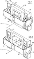
FIG. 1 , there is shown a prior artlinear motor 10 with a frictionlessflexural suspension element 16 fromUS Patent 6,405,599 . Astator assembly 12 includes aframe 11 to which acore portion 13 is mechanically attached. Theframe 11 serves as an element which provides convenient coupling of thecore portion 13 and other elements of thelinear motor 10. Other embodiments of thestator assembly 12 may not require theframe 11. The frictionlessflexural suspension system 16 holds anarmature 14 in position relative to other linear motor elements and controls the motion of thearmature 14 and may exert a restorative force along theaxis 17 of thearmature 14. - Referring to
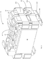
FIG. 2 , there is shown theframe 11, frictionlessflexural suspension system 16, andarmature 14. For clarity, thecore portion 13 is not shown. The frictionlessflexural suspension system 16 includes twoflexure components components pressure plate 15. The rivets "sandwich" theflexure components pressure plate 15 and theframe 11. Theflexure components axis 17 and may be made of stainless steel with a thickness of 0.33 mm (0.012 inches). There is asingle flexure component armature 14, and each flexure component has a longest portion which is substantially parallel with a longest portion of the other flexure component. Eachflexure armature 14. -
US2007/0292286 discloses the pre-characterising features of claim 1. - According to the invention as defined in claim 1, there is provided an electromagnetic motor, comprising:
- a stator; and an armature arranged to move substantially linearly relative to the stator in an intended direction during operation of the motor;
- characterised by further comprising a cross-flexure arrangement including:
an outer first and an inner second flexure connected to a first end of the armature, wherein the inner second flexure is split into two parallel flexures with a gap provided therebetween, each flexure having a longest portion which lies substantially in a flexure plane that intersects an armature plane in which the armature lies at a substantially right angle, the flexures allowing motion of the armature in the intended direction while resisting motion of the armature in one or more other degrees of freedom, wherein the longest portion of the outer first flexure is positioned orthogonal the longest portion of the inner second flexure. - The present invention further provides an electromagnetic motor as defined in the dependent claims 2 - 6.
- Embodiments may include one or more of the following features. The motor includes one or more permanent magnets that are secured to the armature. The motor further includes a fourth flexure connected to the first end of the armature, the fourth flexure (a) having a longest portion which is skewed relative to at least two of the longest portions of the outer first or inner second flexures, and (b) allowing motion of the armature in the intended direction while resisting motion of the armature in one or more other degrees of freedom. The motor further includes a fifth flexure connected to a second end of the armature, the fifth flexure (a) having a longest portion which is skewed relative to at least one of the longest portions of the outer first, inner second, or fourth flexures, and (b) allowing motion of the armature in the intended direction while resisting motion of the armature in one or more other degrees of freedom. The motor further includes a sixth flexure connected to the second end of the armature, the sixth flexure (a) having a longest portion which is skewed relative to at least one of the longest portions of the outer first, inner second, fourth or fifth flexures, and (b) allowing motion of the armature in the intended direction while resisting motion of the armature in one or more other degrees of freedom. The motor further includes a housing, and each flexure has two end portions which are connected to the housing and a central portion which is connected to a first end of the armature.
-
-
Fig. 1 is an isometric view of a prior art linear motor; -
FIG. 2 is an isometric view of selected elements of the prior art motor assembly ofFIG. 1 ; -
FIG. 3 is a perspective view of a linear electromagnetic motor; -
FIG. 4 is a partially exploded perspective view of the motor ofFig. 3 ; -
FIG. 5 is a perspective view of the motor ofFig. 3 in which an external housing of the motor has been removed; -
FIG. 6 is a perspective view of the motor ofFig. 5 in which stator back irons have been removed; and -
FIG 7 is a perspective view of a motor similar to the motor ofFig. 6 in which the load plate has been removed and the armature frame has been modified. - The description below discloses a linear electromagnetic motor in which two pairs of flexural suspension elements (i.e. flexures) are connected to each end of an armature of the motor. These flexures allow frictionless movement of the armature in an intended direction of travel while providing resistance to movement of the armature in other degrees of freedom (translation, rotation). In some applications of the motor, loading in the transverse (or lateral) directions can be substantial and arbitrary in direction.
- With reference to
Fig. 3 , a linearelectromagnetic motor 19 includes ahousing 21. Four flexural suspension elements (i.e. flexures) 23A-D are located at one end of themotor 19, and fourflexures 25A-D are located at the other end of themotor 19. Each flexure is connected to thehousing 21 by riveting both end portions of a particular flexure to the housing (rivets not shown). For example, theflexure 23A is riveted to thehousing 21 atlocations housing 21 in other ways (e.g. bolting, welding). These flexures are also connected to an armature of the motor and allow frictionless movement of the armature in an intended direction of travel (described in further detail below). - The material used for the flexure is selected based on various needs, such as the expected or targeted stress, strain, stiffness (e.g. to prevent the armature from contacting a stator of the motor 19), deflection capability, load handling capacity, number of duty cycles, and operating temperature..Each flexure may be formed from a single piece of flexible material, such as metal (e.g. spring steel), plastic (e.g., Dupont Vespel), or composite. In some examples, one material criteria for the flexure is that it exhibits high fatigue resistance, e.g., it can withstand a maximum stress over a billion cycles. High fatigue resistant (100 ksi or greater endurance limit) materials include, stainless steel alloys. Further details of flexures are disclosed in
US Patents 6,405,599 and7,679,229 '. - Stress, stiffness, size, and linearity are all interrelated in the design of flexures for a moving magnet motor. As size is decreased, for example, the behavior of the flexure (force exerted as a function of displacement) tends to become less linear. Reducing intrinsic stress in the flexure tends to make the behavior more linear. For a prescribed displacement, reducing stiffness allows the flexure to withstand greater applied stress. For a given application, i.e., a motor having particular operating characteristics and packaging constraints, a particular combination of intrinsic stress, stiffness, size, and linearity in the flexures and the ability to withstand the highest amount of applied stress can be achieved by varying the shape of the flexure. The flexures can be formed in several different ways, including stamping or forming, bending using a brake press, and bending with hand tools. The particular techniques used may depend on the material used and typical manufacturing considerations such as capacity, throughput, and quality control.
- Turning to
Fig. 4 , across-support 22 is secured to a first end of anarmature 24 by, for example, rivets (not shown), welding, or an interference fit (or another suitable attachment method). A set ofaxes 25 is provided for reference. Note that a second end of thearmature 24 includes a similar cross-support which is not visible inFig. 4 . Both ends of themotor 19 are substantially similar, so only one end will be described. Amiddle portion 26 offlexure 23A is connected to aportion 28 of thecross-support 22. Amiddle portion 30 offlexure 23B is connected to aportion 32 of thecross-support 22. Amiddle portion 34 offlexure 23C is connected to aportion 36 of thecross-support 22. Amiddle portion 38 offlexure 23D is connected to aportion 40 of thecross-support 22.Portions cross-support 22 each have a pair of through holes for receiving rivets or bolts. In this case, through holes would need to be created in themiddle portions flexures Flexures 23A-D are thus connected to a first end of thearmature 24, andflexures 25A-D are connected to a second end of thearmature 24. The longest portions of theflexures 23A-D and 25A-D reside in planes substantially parallel with each other. - Having a cross-flexure arrangement can make it challenging to connect the
armature 24 to the outer flexure(s) (e.g. 23A, 23B). Splitting the inner flexure into two portions (e.g. 23C, 23D) and providing a gap betweenflexures portions flexures portions Flexures Flexures Flexures - Referring to
Fig. 5 , the housing of themotor 19 has been removed to facilitate viewing of the interior of the motor. Theflexures 23A-D are back in the same positions as inFig. 1 . A pair of stator backirons conductive wire 47. The stator back irons are preferably made of a material which has high thermal conductivity, thereby facilitating removal of thermal energy generated in the wire coils. Aload plate 49 is secured to the cross-support 22 (e.g. by welding) and thus thearmature 24. Theload plate 49 can be connected to an external load (not shown) on which themotor 19 can act. - In
Fig. 6 the stator back irons have been removed in order to facilitate viewing of the stator wire coils 47. During operation of themotor 19, magnetic fields from amagnetic assembly 50 that has one or more permanent magnets interact with the magnetic fields generated by the electrical current flowing in the stator wire coils 47. This interaction causes thearmature 24 to move substantially linearly back and forth relative to thehousing 21 in an intended direction of movement which is substantially parallel to the X axis of the coordinateaxes system 56. A load connected to theload plate 49 will likewise be moved back and forth in the same intended direction. - As further shown in
Fig. 6 , each of theflexures 23A-D and 25A-D has a longest portion which lies substantially in a plane that intersects a plane in which the armature lies at a substantially right angle. Pairs of flexures have longest portions which lie in the same plane and are substantially parallel to each other. For example,flexures flexure 23A has a longest portion which is skewed relative to a longest portion of each of flexures 23C, 23D, 25C and 25D. The word "skewed" as used in this application means that a first flexure does not intersect a second flexure and is not parallel with the second flexure. Each flexure has a longest portion which is substantially parallel to the longest portions of two of the flexures on the opposite end of the armature (e.g. flexure 23A has a longest portion which is substantially parallel with the longest portions offlexures 25A and B).Flexures 23A-D and 25A-D allow motion of thearmature 24 in the intended direction of movement while resisting motion of the armature in one or more other degrees of freedom (i.e. translation along a direction parallel to the Y and/or Z axes, and/or rotation about axes which are parallel to the X, Y and/or Z axes). - Another example of an
armature 58 is disclosed inFig. 7 . The other elements inFig. 7 are substantially the same as inFig. 6 except that theload plate 49 has been removed. Thearmature 58 is similar to thearmature 24 except that thearmature 58 has two modifiedcorners 60 and 62 which are adapted to have an external load attached thereto. In this example there is a through hole at eachcorner 60 and 62 of the armature which allows the external load to be, for example, bolted to thecorners 60 and 62. This arrangement attaches the armature to the external load at locations outside the magnet load path and directly onto a more structural part of the armature frame. - In another example, the stator coils 47 are attached to the load and the
armature 24 containing themagnet assembly 50 is held in a fixed position relative to the housing. In this case thecoils 47 are also connected to theflexures 23A-D and 25A-D so that the coils can move in the X direction. This is a moving voice coil motor as opposed to a moving magnet motor which is described above. To summarize, the linear electro-magnetic motor allows relative motion between the stator and the armature. In some examples the armature is coupled to the load to cause the load to move linearly, and in other examples the stator is coupled to the load to cause the load to move linearly. - It will be understood that additional modifications may be made within the scope of the following claims.
Claims (6)
- An electromagnetic motor (19), comprising:a stator; andan armature (24) arranged to move substantially linearly relative to the stator in an intended direction during operation of the motor; characterized by further comprising a cross-flexure arrangement including:
an outer first (23A, 23B, 25A, 25B) and an inner second (23C, 23D, 25C, 25D) flexure connected to a first end of the armature, wherein the inner second flexure is split into two parallel flexures with a gap provided therebetween, each flexure having a longest portion which lies substantially in a flexure plane that intersects an armature plane in which the armature lies at a substantially right angle, the flexures allowing motion of the armature in the intended direction while resisting motion of the armature in one or more other degrees of freedom, wherein the longest portion of the outer first flexure is positioned orthogonal to the longest portion of the inner second flexure. - The electromagnetic motor of claim 1, further comprising one or more permanent magnets that are secured to the armature.
- The electromagnetic motor of claim 1, further comprising a fourth flexure connected to the first end of the armature, the fourth flexure (a) having a longest portion which does not intersect and is not parallel with at least two of the longest portions of the outer first or inner second flexures, and (b) allowing motion of the armature in the intended direction while resisting motion of the armature in one or more other degrees of freedom.
- The electromagnetic motor of claim 3, further comprising a fifth flexure connected to a second end of the armature, the fifth flexure (a) having a longest portion which does not intersect and is not parallel with at least one of the longest portions of the outer first, inner second, or fourth flexures, and (b) allowing motion of the armature in the intended direction while resisting motion of the armature in one or more other degrees of freedom.
- The electromagnetic motor of claim 4, further comprising a sixth flexure connected to the second end of the armature, the sixth flexure (a) having a longest portion which does not intersect and is not parallel with at least one of the longest portions of the outer first, inner second, fourth, or fifth flexures, and (b) allowing motion of the armature in the intended direction while resisting motion of the armature in one or more other degrees of freedom.
- The electromagnetic motor of claim 1, further including a housing (21), wherein each flexure has two end portions which are connected to the housing and a central portion which is connected to a first end of the armature.
Applications Claiming Priority (2)
| Application Number | Priority Date | Filing Date | Title |
|---|---|---|---|
| US13/591,938 US9496778B2 (en) | 2012-08-22 | 2012-08-22 | Electromagnetic motor |
| PCT/US2013/055148 WO2014031439A1 (en) | 2012-08-22 | 2013-08-15 | Electromagnetic motor |
Publications (2)
| Publication Number | Publication Date |
|---|---|
| EP2888808A1 EP2888808A1 (en) | 2015-07-01 |
| EP2888808B1 true EP2888808B1 (en) | 2020-11-25 |
Family
ID=49029256
Family Applications (1)
| Application Number | Title | Priority Date | Filing Date |
|---|---|---|---|
| EP13752797.4A Active EP2888808B1 (en) | 2012-08-22 | 2013-08-15 | Electromagnetic motor |
Country Status (3)
| Country | Link |
|---|---|
| US (2) | US9496778B2 (en) |
| EP (1) | EP2888808B1 (en) |
| WO (1) | WO2014031439A1 (en) |
Families Citing this family (15)
| Publication number | Priority date | Publication date | Assignee | Title |
|---|---|---|---|---|
| DE102016100809A1 (en) * | 2015-04-14 | 2016-10-20 | Samsung Electronics Co. Ltd. | Nahfeldkommunikationsbaugruppe and portable device containing the same |
| EP3300861B1 (en) | 2016-09-28 | 2019-07-03 | Braun GmbH | Electrically driven device |
| EP3396828B1 (en) | 2017-04-27 | 2021-08-18 | Braun GmbH | Electric appliance for personal care |
| EP3396821B1 (en) | 2017-04-27 | 2023-06-14 | Braun GmbH | Electric shaver |
| EP3396827B1 (en) | 2017-04-27 | 2023-06-28 | Braun GmbH | Electric appliance for personal care |
| EP3396826B1 (en) * | 2017-04-27 | 2022-10-19 | Braun GmbH | Electric appliance for personal care |
| FR3074620B1 (en) * | 2017-12-05 | 2019-10-25 | Ams R&D Sas | ELECTRIC MOTOR |
| CN109803216B (en) * | 2019-01-15 | 2020-11-20 | 哈尔滨工程大学 | A moving magnet linear actuator |
| US11843301B2 (en) | 2019-01-22 | 2023-12-12 | Waters Technologies Corporation | Linear motor |
| JP7533871B2 (en) * | 2020-01-15 | 2024-08-14 | ミネベアミツミ株式会社 | Vibration actuator and electronic device |
| US20210257896A1 (en) * | 2020-02-17 | 2021-08-19 | Dan Haronian | Movement and Vibration energy harvesting |
| JP7504624B2 (en) * | 2020-02-28 | 2024-06-24 | キヤノン株式会社 | Power generating element and device using the power generating element |
| CN111404346B (en) * | 2020-04-16 | 2021-06-25 | 浙江省东阳市东磁诚基电子有限公司 | A moving magnet type multidirectional vibration linear motor structure and its realization method |
| US12278537B2 (en) * | 2021-05-05 | 2025-04-15 | Enervibe Ltd. | Electromagnetic vibration and energy harvester |
| US11936269B2 (en) * | 2021-09-22 | 2024-03-19 | Apple Inc. | Haptic engine based on angular resonant actuator with pivot axis and mass center that differ |
Citations (1)
| Publication number | Priority date | Publication date | Assignee | Title |
|---|---|---|---|---|
| US7550880B1 (en) * | 2006-04-12 | 2009-06-23 | Motran Industries Inc | Folded spring flexure suspension for linearly actuated devices |
Family Cites Families (28)
| Publication number | Priority date | Publication date | Assignee | Title |
|---|---|---|---|---|
| US3336488A (en) | 1964-08-03 | 1967-08-15 | Elmer E Scott | Oscillating motor |
| US3746937A (en) | 1971-07-12 | 1973-07-17 | H Koike | Electromagnetic linear motion device |
| DE2135929B1 (en) | 1971-07-17 | 1972-12-21 | Saia Ag, Murten (Schweiz) | DEVICE FOR GENERATING A ROTATING MOTION WITH AT LEAST ONE PULSING DRIVE FORCE |
| DE2634748A1 (en) | 1976-01-20 | 1978-02-09 | Hans Meyer | SKI WITH SPRING BOARD |
| US4538964A (en) | 1984-01-04 | 1985-09-03 | Mechanical Technology Incorporated | Multistage resonant compressor |
| US4726227A (en) | 1984-10-22 | 1988-02-23 | United Technologies Corporation | Angular velocity sensor having low temperature sensitivity |
| US4675615A (en) | 1985-12-30 | 1987-06-23 | Donato Bramanti | Magnetic amplifier |
| FR2659717A1 (en) | 1990-03-19 | 1991-09-20 | Kodak Pathe | METHOD AND DEVICE FOR ANIMATING A SURFACE OF A BACK-AND-COMBINATION MOTION IN A PLANE. |
| US5269497A (en) | 1990-12-17 | 1993-12-14 | Flexsteel Industries, Inc. | Seat spring structure |
| US5216723A (en) | 1991-03-11 | 1993-06-01 | Bose Corporation | Permanent magnet transducing |
| JP2518671Y2 (en) * | 1991-06-13 | 1996-11-27 | 住友重機械工業株式会社 | Gas cycle engine for chiller |
| ES2246208T3 (en) | 1999-11-05 | 2006-02-16 | Sebert Schwingungstechnik Gmbh | AMORTIGUATION PROVISION. |
| US6405599B1 (en) | 2000-01-13 | 2002-06-18 | Bose Corporation | Frictionless motor material testing |
| DK2298370T3 (en) | 2002-02-21 | 2014-01-27 | Design Mentor Inc | fluid pump |
| JP3928495B2 (en) | 2002-06-17 | 2007-06-13 | 松下電工株式会社 | Vibration type linear actuator |
| JP3928619B2 (en) | 2003-12-26 | 2007-06-13 | 松下電工株式会社 | Vibration type linear actuator |
| DE102004062307A1 (en) * | 2004-12-23 | 2006-07-13 | BSH Bosch und Siemens Hausgeräte GmbH | linear compressor |
| DE102004062300A1 (en) * | 2004-12-23 | 2006-07-13 | BSH Bosch und Siemens Hausgeräte GmbH | linear compressor |
| DE102004062301A1 (en) * | 2004-12-23 | 2006-07-13 | BSH Bosch und Siemens Hausgeräte GmbH | Linear compressor and drive unit for it |
| DE102004062298A1 (en) | 2004-12-23 | 2006-07-13 | BSH Bosch und Siemens Hausgeräte GmbH | linear compressor |
| DE102004062302A1 (en) * | 2004-12-23 | 2006-07-13 | BSH Bosch und Siemens Hausgeräte GmbH | Linear compressor and drive unit for it |
| DE102006009232A1 (en) * | 2006-02-28 | 2007-08-30 | BSH Bosch und Siemens Hausgeräte GmbH | Power supply unit for linear compressor in cooling equipment has coil spring that is expandable and compressible, and which is biased against swinging body |
| US7679229B2 (en) | 2007-10-12 | 2010-03-16 | Bose Corporation | Relieving stress in a flexure |
| US7694593B2 (en) | 2008-05-13 | 2010-04-13 | Bose Corporation | Multi-sample conditioning system |
| CN101902115B (en) | 2009-05-25 | 2013-02-13 | 三星电机株式会社 | Linear vibrator |
| US9048717B2 (en) | 2009-09-16 | 2015-06-02 | Ecoharvester, Inc. | Multipolar electromagnetic generator |
| US8295536B2 (en) | 2010-03-31 | 2012-10-23 | Bose Corporation | Moving magnet levered loudspeaker |
| US8295537B2 (en) | 2010-03-31 | 2012-10-23 | Bose Corporation | Loudspeaker moment and torque balancing |
-
2012
- 2012-08-22 US US13/591,938 patent/US9496778B2/en active Active
-
2013
- 2013-08-15 WO PCT/US2013/055148 patent/WO2014031439A1/en not_active Ceased
- 2013-08-15 EP EP13752797.4A patent/EP2888808B1/en active Active
-
2016
- 2016-11-11 US US15/349,618 patent/US9768675B2/en active Active
Patent Citations (1)
| Publication number | Priority date | Publication date | Assignee | Title |
|---|---|---|---|---|
| US7550880B1 (en) * | 2006-04-12 | 2009-06-23 | Motran Industries Inc | Folded spring flexure suspension for linearly actuated devices |
Also Published As
| Publication number | Publication date |
|---|---|
| EP2888808A1 (en) | 2015-07-01 |
| US9768675B2 (en) | 2017-09-19 |
| US20140054980A1 (en) | 2014-02-27 |
| US20170163139A1 (en) | 2017-06-08 |
| WO2014031439A1 (en) | 2014-02-27 |
| US9496778B2 (en) | 2016-11-15 |
Similar Documents
| Publication | Publication Date | Title |
|---|---|---|
| US9768675B2 (en) | Electromagnetic motor | |
| US8295537B2 (en) | Loudspeaker moment and torque balancing | |
| US8295536B2 (en) | Moving magnet levered loudspeaker | |
| US7679229B2 (en) | Relieving stress in a flexure | |
| US20110198945A1 (en) | Linear actuator | |
| EP3060356B1 (en) | Mechanical resonant system | |
| US9357279B2 (en) | Elastomeric torsion bushings for levered loudspeakers | |
| JP2016519915A (en) | Reaction compensation tilt platform | |
| CN118040936A (en) | Linear motor | |
| US7595944B2 (en) | Optical actuator | |
| CN117524511B (en) | Reflux coil assembly and toroidal field coil structure | |
| EP3396976B1 (en) | Electromechanical transducer | |
| US20110050006A1 (en) | Actuator | |
| JPH055501B2 (en) | ||
| JP7311693B2 (en) | vibration actuator | |
| JP5370820B2 (en) | Linear actuator and method of assembling the same | |
| JP6625896B2 (en) | Electromechanical transducer | |
| EP2689521B1 (en) | Magneto-inductive energy harvesting | |
| EP4742282A1 (en) | Electromagnetic linear actuator | |
| CN212257293U (en) | Contactor armature moving mechanism | |
| JP6239431B2 (en) | Power generation element | |
| CN118040935A (en) | Magnet assembly and linear motor | |
| CN121124498A (en) | Magnetic levitation constrained long-stroke vibration isolation pointing actuator and precision vibration isolation pointing method | |
| JP2008271623A (en) | Shaft fixing tool for shaft type linear motor and linear motion device having the same | |
| HK1174762B (en) | Loudspeaker having moment and torque balancing |
Legal Events
| Date | Code | Title | Description |
|---|---|---|---|
| PUAI | Public reference made under article 153(3) epc to a published international application that has entered the european phase |
Free format text: ORIGINAL CODE: 0009012 |
|
| 17P | Request for examination filed |
Effective date: 20150224 |
|
| AK | Designated contracting states |
Kind code of ref document: A1 Designated state(s): AL AT BE BG CH CY CZ DE DK EE ES FI FR GB GR HR HU IE IS IT LI LT LU LV MC MK MT NL NO PL PT RO RS SE SI SK SM TR |
|
| AX | Request for extension of the european patent |
Extension state: BA ME |
|
| RAP1 | Party data changed (applicant data changed or rights of an application transferred) |
Owner name: TA INSTRUMENTS-WATERS LLC |
|
| DAX | Request for extension of the european patent (deleted) | ||
| STAA | Information on the status of an ep patent application or granted ep patent |
Free format text: STATUS: EXAMINATION IS IN PROGRESS |
|
| 17Q | First examination report despatched |
Effective date: 20190219 |
|
| GRAP | Despatch of communication of intention to grant a patent |
Free format text: ORIGINAL CODE: EPIDOSNIGR1 |
|
| STAA | Information on the status of an ep patent application or granted ep patent |
Free format text: STATUS: GRANT OF PATENT IS INTENDED |
|
| INTG | Intention to grant announced |
Effective date: 20200617 |
|
| RIN1 | Information on inventor provided before grant (corrected) |
Inventor name: ANDRIKOWICH, TOM Inventor name: NICKEL, TROY D. |
|
| GRAS | Grant fee paid |
Free format text: ORIGINAL CODE: EPIDOSNIGR3 |
|
| GRAA | (expected) grant |
Free format text: ORIGINAL CODE: 0009210 |
|
| STAA | Information on the status of an ep patent application or granted ep patent |
Free format text: STATUS: THE PATENT HAS BEEN GRANTED |
|
| AK | Designated contracting states |
Kind code of ref document: B1 Designated state(s): AL AT BE BG CH CY CZ DE DK EE ES FI FR GB GR HR HU IE IS IT LI LT LU LV MC MK MT NL NO PL PT RO RS SE SI SK SM TR |
|
| REG | Reference to a national code |
Ref country code: GB Ref legal event code: FG4D |
|
| REG | Reference to a national code |
Ref country code: CH Ref legal event code: EP |
|
| REG | Reference to a national code |
Ref country code: DE Ref legal event code: R096 Ref document number: 602013074306 Country of ref document: DE |
|
| REG | Reference to a national code |
Ref country code: AT Ref legal event code: REF Ref document number: 1339424 Country of ref document: AT Kind code of ref document: T Effective date: 20201215 |
|
| REG | Reference to a national code |
Ref country code: IE Ref legal event code: FG4D |
|
| REG | Reference to a national code |
Ref country code: AT Ref legal event code: MK05 Ref document number: 1339424 Country of ref document: AT Kind code of ref document: T Effective date: 20201125 |
|
| REG | Reference to a national code |
Ref country code: NL Ref legal event code: MP Effective date: 20201125 |
|
| PG25 | Lapsed in a contracting state [announced via postgrant information from national office to epo] |
Ref country code: GR Free format text: LAPSE BECAUSE OF FAILURE TO SUBMIT A TRANSLATION OF THE DESCRIPTION OR TO PAY THE FEE WITHIN THE PRESCRIBED TIME-LIMIT Effective date: 20210226 Ref country code: RS Free format text: LAPSE BECAUSE OF FAILURE TO SUBMIT A TRANSLATION OF THE DESCRIPTION OR TO PAY THE FEE WITHIN THE PRESCRIBED TIME-LIMIT Effective date: 20201125 Ref country code: FI Free format text: LAPSE BECAUSE OF FAILURE TO SUBMIT A TRANSLATION OF THE DESCRIPTION OR TO PAY THE FEE WITHIN THE PRESCRIBED TIME-LIMIT Effective date: 20201125 Ref country code: NO Free format text: LAPSE BECAUSE OF FAILURE TO SUBMIT A TRANSLATION OF THE DESCRIPTION OR TO PAY THE FEE WITHIN THE PRESCRIBED TIME-LIMIT Effective date: 20210225 Ref country code: PT Free format text: LAPSE BECAUSE OF FAILURE TO SUBMIT A TRANSLATION OF THE DESCRIPTION OR TO PAY THE FEE WITHIN THE PRESCRIBED TIME-LIMIT Effective date: 20210325 |
|
| PG25 | Lapsed in a contracting state [announced via postgrant information from national office to epo] |
Ref country code: BG Free format text: LAPSE BECAUSE OF FAILURE TO SUBMIT A TRANSLATION OF THE DESCRIPTION OR TO PAY THE FEE WITHIN THE PRESCRIBED TIME-LIMIT Effective date: 20210225 Ref country code: AT Free format text: LAPSE BECAUSE OF FAILURE TO SUBMIT A TRANSLATION OF THE DESCRIPTION OR TO PAY THE FEE WITHIN THE PRESCRIBED TIME-LIMIT Effective date: 20201125 Ref country code: LV Free format text: LAPSE BECAUSE OF FAILURE TO SUBMIT A TRANSLATION OF THE DESCRIPTION OR TO PAY THE FEE WITHIN THE PRESCRIBED TIME-LIMIT Effective date: 20201125 Ref country code: PL Free format text: LAPSE BECAUSE OF FAILURE TO SUBMIT A TRANSLATION OF THE DESCRIPTION OR TO PAY THE FEE WITHIN THE PRESCRIBED TIME-LIMIT Effective date: 20201125 Ref country code: SE Free format text: LAPSE BECAUSE OF FAILURE TO SUBMIT A TRANSLATION OF THE DESCRIPTION OR TO PAY THE FEE WITHIN THE PRESCRIBED TIME-LIMIT Effective date: 20201125 Ref country code: IS Free format text: LAPSE BECAUSE OF FAILURE TO SUBMIT A TRANSLATION OF THE DESCRIPTION OR TO PAY THE FEE WITHIN THE PRESCRIBED TIME-LIMIT Effective date: 20210325 |
|
| REG | Reference to a national code |
Ref country code: LT Ref legal event code: MG9D |
|
| PG25 | Lapsed in a contracting state [announced via postgrant information from national office to epo] |
Ref country code: HR Free format text: LAPSE BECAUSE OF FAILURE TO SUBMIT A TRANSLATION OF THE DESCRIPTION OR TO PAY THE FEE WITHIN THE PRESCRIBED TIME-LIMIT Effective date: 20201125 |
|
| PG25 | Lapsed in a contracting state [announced via postgrant information from national office to epo] |
Ref country code: SK Free format text: LAPSE BECAUSE OF FAILURE TO SUBMIT A TRANSLATION OF THE DESCRIPTION OR TO PAY THE FEE WITHIN THE PRESCRIBED TIME-LIMIT Effective date: 20201125 Ref country code: RO Free format text: LAPSE BECAUSE OF FAILURE TO SUBMIT A TRANSLATION OF THE DESCRIPTION OR TO PAY THE FEE WITHIN THE PRESCRIBED TIME-LIMIT Effective date: 20201125 Ref country code: LT Free format text: LAPSE BECAUSE OF FAILURE TO SUBMIT A TRANSLATION OF THE DESCRIPTION OR TO PAY THE FEE WITHIN THE PRESCRIBED TIME-LIMIT Effective date: 20201125 Ref country code: EE Free format text: LAPSE BECAUSE OF FAILURE TO SUBMIT A TRANSLATION OF THE DESCRIPTION OR TO PAY THE FEE WITHIN THE PRESCRIBED TIME-LIMIT Effective date: 20201125 Ref country code: CZ Free format text: LAPSE BECAUSE OF FAILURE TO SUBMIT A TRANSLATION OF THE DESCRIPTION OR TO PAY THE FEE WITHIN THE PRESCRIBED TIME-LIMIT Effective date: 20201125 Ref country code: SM Free format text: LAPSE BECAUSE OF FAILURE TO SUBMIT A TRANSLATION OF THE DESCRIPTION OR TO PAY THE FEE WITHIN THE PRESCRIBED TIME-LIMIT Effective date: 20201125 |
|
| REG | Reference to a national code |
Ref country code: DE Ref legal event code: R097 Ref document number: 602013074306 Country of ref document: DE |
|
| PG25 | Lapsed in a contracting state [announced via postgrant information from national office to epo] |
Ref country code: DK Free format text: LAPSE BECAUSE OF FAILURE TO SUBMIT A TRANSLATION OF THE DESCRIPTION OR TO PAY THE FEE WITHIN THE PRESCRIBED TIME-LIMIT Effective date: 20201125 |
|
| PLBE | No opposition filed within time limit |
Free format text: ORIGINAL CODE: 0009261 |
|
| STAA | Information on the status of an ep patent application or granted ep patent |
Free format text: STATUS: NO OPPOSITION FILED WITHIN TIME LIMIT |
|
| PG25 | Lapsed in a contracting state [announced via postgrant information from national office to epo] |
Ref country code: IT Free format text: LAPSE BECAUSE OF FAILURE TO SUBMIT A TRANSLATION OF THE DESCRIPTION OR TO PAY THE FEE WITHIN THE PRESCRIBED TIME-LIMIT Effective date: 20201125 Ref country code: AL Free format text: LAPSE BECAUSE OF FAILURE TO SUBMIT A TRANSLATION OF THE DESCRIPTION OR TO PAY THE FEE WITHIN THE PRESCRIBED TIME-LIMIT Effective date: 20201125 Ref country code: NL Free format text: LAPSE BECAUSE OF FAILURE TO SUBMIT A TRANSLATION OF THE DESCRIPTION OR TO PAY THE FEE WITHIN THE PRESCRIBED TIME-LIMIT Effective date: 20201125 |
|
| 26N | No opposition filed |
Effective date: 20210826 |
|
| PG25 | Lapsed in a contracting state [announced via postgrant information from national office to epo] |
Ref country code: ES Free format text: LAPSE BECAUSE OF FAILURE TO SUBMIT A TRANSLATION OF THE DESCRIPTION OR TO PAY THE FEE WITHIN THE PRESCRIBED TIME-LIMIT Effective date: 20201125 Ref country code: SI Free format text: LAPSE BECAUSE OF FAILURE TO SUBMIT A TRANSLATION OF THE DESCRIPTION OR TO PAY THE FEE WITHIN THE PRESCRIBED TIME-LIMIT Effective date: 20201125 |
|
| REG | Reference to a national code |
Ref country code: CH Ref legal event code: PL |
|
| PG25 | Lapsed in a contracting state [announced via postgrant information from national office to epo] |
Ref country code: MC Free format text: LAPSE BECAUSE OF FAILURE TO SUBMIT A TRANSLATION OF THE DESCRIPTION OR TO PAY THE FEE WITHIN THE PRESCRIBED TIME-LIMIT Effective date: 20201125 |
|
| REG | Reference to a national code |
Ref country code: BE Ref legal event code: MM Effective date: 20210831 |
|
| PG25 | Lapsed in a contracting state [announced via postgrant information from national office to epo] |
Ref country code: LI Free format text: LAPSE BECAUSE OF NON-PAYMENT OF DUE FEES Effective date: 20210831 Ref country code: CH Free format text: LAPSE BECAUSE OF NON-PAYMENT OF DUE FEES Effective date: 20210831 |
|
| PG25 | Lapsed in a contracting state [announced via postgrant information from national office to epo] |
Ref country code: IS Free format text: LAPSE BECAUSE OF FAILURE TO SUBMIT A TRANSLATION OF THE DESCRIPTION OR TO PAY THE FEE WITHIN THE PRESCRIBED TIME-LIMIT Effective date: 20210325 Ref country code: LU Free format text: LAPSE BECAUSE OF NON-PAYMENT OF DUE FEES Effective date: 20210815 |
|
| PG25 | Lapsed in a contracting state [announced via postgrant information from national office to epo] |
Ref country code: IE Free format text: LAPSE BECAUSE OF NON-PAYMENT OF DUE FEES Effective date: 20210815 Ref country code: FR Free format text: LAPSE BECAUSE OF NON-PAYMENT OF DUE FEES Effective date: 20210831 Ref country code: BE Free format text: LAPSE BECAUSE OF NON-PAYMENT OF DUE FEES Effective date: 20210831 |
|
| REG | Reference to a national code |
Ref country code: DE Ref legal event code: R082 Ref document number: 602013074306 Country of ref document: DE Representative=s name: FORRESTERS IP LLP, DE Ref country code: DE Ref legal event code: R082 Ref document number: 602013074306 Country of ref document: DE Representative=s name: KUEHR, VERA, DIPL.-BIOL., DE |
|
| PG25 | Lapsed in a contracting state [announced via postgrant information from national office to epo] |
Ref country code: HU Free format text: LAPSE BECAUSE OF FAILURE TO SUBMIT A TRANSLATION OF THE DESCRIPTION OR TO PAY THE FEE WITHIN THE PRESCRIBED TIME-LIMIT; INVALID AB INITIO Effective date: 20130815 |
|
| PG25 | Lapsed in a contracting state [announced via postgrant information from national office to epo] |
Ref country code: CY Free format text: LAPSE BECAUSE OF FAILURE TO SUBMIT A TRANSLATION OF THE DESCRIPTION OR TO PAY THE FEE WITHIN THE PRESCRIBED TIME-LIMIT Effective date: 20201125 |
|
| P01 | Opt-out of the competence of the unified patent court (upc) registered |
Effective date: 20230609 |
|
| P02 | Opt-out of the competence of the unified patent court (upc) changed |
Effective date: 20230619 |
|
| REG | Reference to a national code |
Ref country code: DE Ref legal event code: R082 Ref document number: 602013074306 Country of ref document: DE Representative=s name: FORRESTERS IP LLP, DE |
|
| PG25 | Lapsed in a contracting state [announced via postgrant information from national office to epo] |
Ref country code: MK Free format text: LAPSE BECAUSE OF FAILURE TO SUBMIT A TRANSLATION OF THE DESCRIPTION OR TO PAY THE FEE WITHIN THE PRESCRIBED TIME-LIMIT Effective date: 20201125 |
|
| PG25 | Lapsed in a contracting state [announced via postgrant information from national office to epo] |
Ref country code: MT Free format text: LAPSE BECAUSE OF FAILURE TO SUBMIT A TRANSLATION OF THE DESCRIPTION OR TO PAY THE FEE WITHIN THE PRESCRIBED TIME-LIMIT Effective date: 20201125 |
|
| PGFP | Annual fee paid to national office [announced via postgrant information from national office to epo] |
Ref country code: DE Payment date: 20250724 Year of fee payment: 13 |
|
| PGFP | Annual fee paid to national office [announced via postgrant information from national office to epo] |
Ref country code: GB Payment date: 20250725 Year of fee payment: 13 |
|
| PG25 | Lapsed in a contracting state [announced via postgrant information from national office to epo] |
Ref country code: TR Free format text: LAPSE BECAUSE OF FAILURE TO SUBMIT A TRANSLATION OF THE DESCRIPTION OR TO PAY THE FEE WITHIN THE PRESCRIBED TIME-LIMIT Effective date: 20201125 |