EP2888728B1 - Network discovery with touchlink option - Google Patents
Network discovery with touchlink option Download PDFInfo
- Publication number
- EP2888728B1 EP2888728B1 EP13785913.8A EP13785913A EP2888728B1 EP 2888728 B1 EP2888728 B1 EP 2888728B1 EP 13785913 A EP13785913 A EP 13785913A EP 2888728 B1 EP2888728 B1 EP 2888728B1
- Authority
- EP
- European Patent Office
- Prior art keywords
- network
- network discovery
- touchlink
- duration
- channel
- Prior art date
- Legal status (The legal status is an assumption and is not a legal conclusion. Google has not performed a legal analysis and makes no representation as to the accuracy of the status listed.)
- Active
Links
- 238000000034 method Methods 0.000 claims description 65
- 239000003999 initiator Substances 0.000 claims description 23
- 230000004044 response Effects 0.000 claims description 7
- 238000004590 computer program Methods 0.000 claims description 5
- 230000000977 initiatory effect Effects 0.000 claims description 2
- 238000010586 diagram Methods 0.000 description 12
- 230000011664 signaling Effects 0.000 description 7
- 230000008569 process Effects 0.000 description 5
- 230000009471 action Effects 0.000 description 2
- 230000008901 benefit Effects 0.000 description 2
- 230000004048 modification Effects 0.000 description 2
- 238000012986 modification Methods 0.000 description 2
- 230000006855 networking Effects 0.000 description 2
- 206010000210 abortion Diseases 0.000 description 1
- 230000000903 blocking effect Effects 0.000 description 1
- 238000004891 communication Methods 0.000 description 1
- 230000001419 dependent effect Effects 0.000 description 1
- 230000006870 function Effects 0.000 description 1
- 230000002452 interceptive effect Effects 0.000 description 1
- 230000007246 mechanism Effects 0.000 description 1
- 230000003287 optical effect Effects 0.000 description 1
Images


Classifications
-
- H—ELECTRICITY
- H04—ELECTRIC COMMUNICATION TECHNIQUE
- H04W—WIRELESS COMMUNICATION NETWORKS
- H04W48/00—Access restriction; Network selection; Access point selection
- H04W48/16—Discovering, processing access restriction or access information
-
- G—PHYSICS
- G08—SIGNALLING
- G08C—TRANSMISSION SYSTEMS FOR MEASURED VALUES, CONTROL OR SIMILAR SIGNALS
- G08C17/00—Arrangements for transmitting signals characterised by the use of a wireless electrical link
- G08C17/02—Arrangements for transmitting signals characterised by the use of a wireless electrical link using a radio link
-
- H—ELECTRICITY
- H04—ELECTRIC COMMUNICATION TECHNIQUE
- H04W—WIRELESS COMMUNICATION NETWORKS
- H04W8/00—Network data management
- H04W8/005—Discovery of network devices, e.g. terminals
-
- H—ELECTRICITY
- H04—ELECTRIC COMMUNICATION TECHNIQUE
- H04W—WIRELESS COMMUNICATION NETWORKS
- H04W84/00—Network topologies
- H04W84/18—Self-organising networks, e.g. ad-hoc networks or sensor networks
Definitions
- the present invention relates to an apparatus, method, and computer program product for performing network discovery of a mesh network such as - but not limited to - a ZigBee Light Link (ZLL) network for intelligent lighting solutions.
- a mesh network such as - but not limited to - a ZigBee Light Link (ZLL) network for intelligent lighting solutions.
- ZLL ZigBee Light Link
- Topology is a type of networking where each (network) node must not only capture and disseminate its own data, but also serve as a relay for other nodes, that is, it must collaborate to propagate the data in the network.
- Fig. 1 shows an exemplary mesh network architecture with a plurality of nodes 10.
- a mesh network can be designed using a flooding technique or a routing technique. When using a routing technique, the message propagates along a path, by hopping from node to node until the destination is reached. To ensure all its paths' availability, a routing network must allow for continuous connections and reconfiguration around broken or blocked paths, using self-healing algorithms.
- ZigBee is a mesh network that relies heavily on a network device called the coordinator. Such a coordinator is assumed to be always available and therefore always powered. In a lighting system intended for the home in a consumer market, this is a heavy constraint. For this reason, other methods were found to benefit from the ZigBee network functionality (especially routing) without the need of having a coordinator. These other methods and other network operations heavily rely on inter-PAN (Personal Area Network) messages. Inter-PAN messages can be transferred between devices that are on the same channel. A special flag in the message indicates to by-pass the ZigBee Network layer and for this reason, the two communicating devices do not need to be part of the same ZigBee network.
- Inter-PAN Personal Area Network
- the ZigBee specification ([ZigBee] 053474r19, October 12) describes in section 3.6.1.2 how devices should join a network through a Medium Access Control (MAC) Association. Prior to doing such a MAC Association, devices should perform a network discovery as described in section 3.6.1.3 of the ZigBee specification. Typically, devices that have not yet joined a network search for an "open" network they can join.
- MAC Medium Access Control
- Fig. 2 shows a schematic flow diagram of a conventional ZigBee network discovery procedure for obtaining an association in a PAN.
- a first channel is determined in step S210 and the scanning system is switched to the determined channel in step S220.
- a single-channel network discovery for an association with a PAN is performed by sending out a beacon request command and waiting some time for a beacon response.
- step S240 it is checked whether the current channel is the last channel to be scanned. If not, the procedure branches off to step S250 where the next channel is determined. Then, the procedure continues with step S220 and a new single-channel network discovery is started. If it is determined in step S240 that the current channel was the last channel, the network discovery procedure ends (E). This whole procedure can be executed once, or can be repeated, possibly indefinitely.
- the ZLL profile addresses devices and functionality in the over-the-counter, consumer lighting application domain. It is based on ZigBee-Pro and utilizes clusters defined in a ZigBee Cluster Library.
- the ZLL specification describes an additional way to join a network, called touchlink commissioning.
- a user may use a ZLL remote control to "touchlink" a ZLL lighting device or application. This instructs the ZLL device or application to either start a new network or to join an existing network of the ZLL remote control.
- touchlink commissioning mechanism will give the consumer a simple and intuitive experience when connecting devices together.
- Touchlinking is a method of finding devices in the neighborhood based on received signal strength.
- a touchlink action is easy for the user to understand and can replace buttons on a device that would otherwise be required to facilitate commissioning.
- the touchlink operation is divided into two parts; device discovery and transferring network settings.
- the result of device discovery is a list of device information which includes network capabilities, device type and whether a device is already participating in a mesh network.
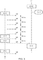
- Fig. 3 shows a schematic flow and signalling diagram of a device discovery procedure based on the touchlink initiator procedure according to section 8.4.1.1 of the above ZLL specification.
- a touchlink target device stays at a fixed channel, e.g., channel 20 (CH20), and listens to scan request commands (step S310).
- the touchlink initiator device first switches to channel 11 (CH11) and broadcast five consecutive inter-PAN scan request command frames (SR), with a duration (aplcScanTimeBaseDuration) of 0.25s between those broadcasts (in which an inter-PAN scan response command frame from the touchlink target device (TT) could be received), followed by a single broadcast at each of the other ZLL primary channels 15, 20 and 25 (CH15, CH20 and CH25), with a duration (aplcScanTimeBaseDuration) of 0.25s between those broadcasts. Accordingly, the touchlink target device (TT) will detect or recognize the scan request command which is issued on the same channel 20 (CH20) and will then handle the scan request command in step S320.
- SR inter-PAN scan request command frames
- the touchlink target device responds to the scan request command by sending an inter-PAN scan response command, which the touchlink initiator device receives.
- the touchlink initiator device then has enough information to select the touchlink target device for the next step in the touchlink procedure.
- the processing in step S320 should be finished before the touchlink initiator switches to the next channel (CH25 in the present example).
- a device implemented according to the ZLL specification that is not yet in a ZigBee network would typically search for a network to join (through MAC Association), but at the same time a user may be trying to discover the device by the above touchlink initiator procedure using e.g. a remote control device. Thus, in this case, the device would also act as a ZLL touchlink target device.
- the reason for the interference is that the network discovery procedure for MAC association requires the ZLL device to scan over a set of RF channels, while for being ZLL touchlink target device the ZLL device is normally required to stay at a fixed channel.
- Fig. 4 shows this interference based on a schematic signalling diagram of a device discovery procedure by a touchlink initiator device (TI) similar to Fig. 3 and a concurrent network discovery procedure by a device (NDD).
- TI touchlink initiator device
- NDD device
- the touchlink initiator device (typically a ZLL remote control device) trying to find the touchlink target (typically a ZLL lighting device) cannot find it, as the touchlink target device (which continuously switches through the channels in accordance with the above ZLL specification and broadcasts respective beacon request commands (BR)) is never at the right moment at the channel the touchlink initiator device uses to transmit its scan request commands (SR).
- a ZLL remote control device trying to find the touchlink target (typically a ZLL lighting device) cannot find it, as the touchlink target device (which continuously switches through the channels in accordance with the above ZLL specification and broadcasts respective beacon request commands (BR)) is never at the right moment at the channel the touchlink initiator device uses to transmit its scan request commands (SR).
- BR beacon request commands
- the channels can be scanned in any order, but the ZLL Profile specification Version 1.0 ([ZLL]; 11-0037-09, March 26 th , 2012) states that first a primary channel set (channels 11, 15, 20 and 25) must be scanned, followed by a secondary channel set (channels 12, 13, 14, 16, 17, 18, 19, 21, 22, 23, 24 and 26), as specified in sections 8.5.1 and 8.1.2 of the above ZLL specification.
- US 2006/0142034 A1 relates to systems and methods for enabling wireless devices to discover a number of proximate wireless devices, wherein the discovery includes the discovery of network configuration parameters useful for establishing a connection between the wireless devices.
- the systems and methods for device discovery apply to timely discover wireless devices that receive communication continuously, as well as wireless devices that turn off their receivers for intermittent periods of time.
- the wireless devices may, for example, communicate using the IEEE 802.11 protocol.
- An object of the present invention is to provide an improved network discovery scheme for a device which allows concurrent discovery of the same device via a remote control or touchlinking.
- the proposed network discovery scheme is enhanced by initiating at least one intermittent switch to a predetermined channel and a listening mode in which a device, which is currently involved in a network discovery process, listens on the predetermined channel for a predetermined duration to allow receipt of a scan request command for device discovery by another device.
- the apparatus may be adapted to initiate the sequential search scan over a primary channel set followed by a secondary channel set. Due to the fact that intermittent switching to the listening mode is ensured, the network discovery scan can be enhanced over primary and secondary channels without increasing the risk of interference with a device discovery procedure by another device.
- the apparatus may be adapted to perform the network discovery for obtaining a MAC association.
- MAC associations can thus be obtained through network discovery without blocking or interfering device discovery by other devices.
- the apparatus may be adapted to repeat the intermittent switch to the listening mode after a third duration selected to be able to receive at least one of a sequence of subsequent scan request commands broadcast by the other device on the predetermined channel.
- the third duration can be set so that it can be ensured that one of the sequence of scan request commands is received.
- the third duration may substantially correspond to the sum of the duration of the sequence and the second predetermined duration.
- the apparatus may be adapted to keep the listening mode while simultaneously performing the search scan. Thereby, overall processing may be streamlined by performing device discovery for touchlinking and network discovery for PAN association in parallel.
- the apparatus may be provided in a wireless device, such as a lighting device of a ZLL system or another ZLL device, which may be a touchlink target device.
- the remote control may be another wireless device which may act as a touchlink initiator device.
- the apparatus may be implemented as a discrete hardware circuitry with discrete hardware components, as an integrated chip, as an arrangement of chip modules, or as a signal processing device or chip controlled by a software routine or program stored in a memory, written on a computer readable medium, or downloaded from a network, such as the Internet.
- a device is allowed to perform a network discovery for a MAC association in a wireless mesh network while at the same time responding to a ZLL touchlink initiator device.
- This modified implementation is based on assumption that it is sufficient to receive at least one of all scan request commands issued during the device discovery process of the remote device.
- RF radio frequency
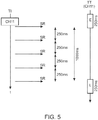
- Fig. 5 shows a schematic flow and signaling diagram of a network discovery procedure according to a first embodiment, where a touchlink initiator device (TI, left portion of Fig. 5 ) switches to channel 11 (CH11) and then issues or broadcasts five scan request commands (SR) with a time period of 250ms between each of them.
- the total duration of the sequence of scan request commands thus amounts to 1000ms.
- the touchlink target device (TT, right portion of Fig. 5 ) may thus start its earliest possible listening mode (E) not more than 250ms prior to the first scan request command of the touchlink initiator device and start its latest possible listening mode (L) not later than the last scan request command at channel 11 of the touchlink initiator device.
- the proposed temporary switching may thus be arranged as an intermittent switching repeated every 1250ms (or faster) to receive at least one of those scan request commands.
- the touchlink target device While the touchlink target device is doing a network discovery according to section 3.6.1.3 of the above ZigBee specification, the touchlink target device switches back to channel 11 often and long enough to ensure that it will receive at least one of those five scan request commands broadcast at channel 11, so that the network discovery for MAC association procedure can be executed while still allowing a touchlink initiator device to discover the touchlink target device.
- Fig. 6 shows a schematic flow diagram of a more detailed network discovery procedure according to a second embodiment.
- a first channel is selected in step S610 and the RF receiver of the concerned network device is switched in step S620 to the selected channel.
- step S630 a single-channel network discovery process is performed by sending out a beacon request command and waiting a first predetermined time period for a beacon response.
- step S640 the RF receiver is switched to a predetermined fixed channel (e.g. channel 11) to enter into an intermittent listening mode for any scan request command. This mode is kept for a second predetermined time period (e.g. 250ms) during step S650. Now, it is checked in step S660 whether any scan request command has been received.
- step S662 the procedure branches off to step S662 and the network discovery procedure is aborted to handle the san request command and allow the initiated device discovery procedure. Otherwise, if it is determined that no scan request command has been received, the procedure proceeds to step S670 and it is checked whether the last channel of the network discovery procedure has been scanned. If not, the procedure branches off to step S672 and the next channel is determined. Then, the procedure returns to step S620 and the receiver is switched to the next channel. Otherwise, if it is determined that the last channel has been scanned, the network discovery procedure is completed and the procedure ends.
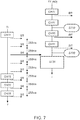
- Fig 7 shows a signalling and flow diagram similar to Figs. 3 , 4 and 5 , based on which the network discovery procedure according to the second embodiment is now described.
- the touchlink target device (TT (ND)) on the right portion of Fig. 7 , which currently performs network discovery for a MAC association sequentially, switches to channels 11 and 15 in order to broadcast its beacon request commands (BR) and listen for any beacon responses.
- the touchlink target device intermittently and periodically switches to a listening mode (steps S710 and S720) for listening on channel 11 for any scan request commands which may be broadcast by a touchlink initiator device (TI).
- TI touchlink initiator device
- the first switch to channel 11 of the procedure is actually redundant and could be omitted in this example, as the first channel of the primary channel mask of the network discovery procedure is the same channel 11.
- Fig. 7 On the left portion of Fig. 7 , the timing of the device discovery procedure of the touchlink initiator device is shown, which starts with a switch to channel 11 and the subsequent five scan request commands followed by other channels as shown in Fig. 3 .
- the third scan request command is broadcast by the touchlink initiator device during a time period where the touchlink target device is in the listening mode and listens to the same channel 11.
- the touchlink target device aborts its network discovery procedure and handles the received scan request command.
- embodiments can be implemented in different ways to handle this, for example performing network discovery for PAN association at multiple channels before switching back to channel 11. That is, the listening mode is not entered after every broadcast of a beacon request. Switch back to the predetermined listening mode channel (e.g. channel 11) can be repeated after a predetermined duration (e.g. at least every 1250ms) and the target device can wait for another predetermined duration (e.g. at least 250ms) so that at least one of the scan request commands is received. Implementations could even choose to exceed these numbers, at the cost of incidental failures.
- the durations need not be predetermined and may instead have respective random lengths (in a certain range).
- the listening mode is only active during steps S640 and S650.
- the listening mode may be active while other steps are being performed, e.g., in S630.
- the listening mode may optionally be active as well. The listening mode may even be always active, so when the search scan takes place, the receiver may switches channel and it may happen that the channel is accidentally at a correct channel to receive a scan request command.
- the scan request command at channel 11 may also be received in the first step while the RF circuit is at channel 11 during network discovery.
- the first two steps of the touchlink target device may be combined in Fig.7 , so that only a single switch to channel 11 is provided.
- the invention can be implemented in any devices that implement the ZLL profile. Typically, these devices have no user controls, such as ZLL lamps or other ZLL devices which actively search for an open network and at the same time allow the user to access the device by a touchlink procedure. Moreover, the above embodiments may be implemented in any mesh network topology which involves network discovery and concurrent device discovery procedures, while the channels and duration may be adapted to the respective system parameters.
- the procedure of Fig. 6 may be implemented as software routine controlling a processor or any other computer system or computing device provided in or at the target device or node.
- the present invention relates to an apparatus, method, and computer program product for controlling network discovery of a wireless mesh network, wherein a modified implementation of the network discovery process is suggested.
- a touchlink target device it is sufficient to receive one of all scan request commands that a touchlink initiator device broadcasts for device discovery on a predetermined channel. It is thus enough for the touchlink target device to intermittently switch its receiver to the predetermined channel for a specific duration to receive at least one of those scan command commands.
Description
- The present invention relates to an apparatus, method, and computer program product for performing network discovery of a mesh network such as - but not limited to - a ZigBee Light Link (ZLL) network for intelligent lighting solutions.
- Mesh networking (topology) is a type of networking where each (network) node must not only capture and disseminate its own data, but also serve as a relay for other nodes, that is, it must collaborate to propagate the data in the network.
-
Fig. 1 shows an exemplary mesh network architecture with a plurality ofnodes 10. A mesh network can be designed using a flooding technique or a routing technique. When using a routing technique, the message propagates along a path, by hopping from node to node until the destination is reached. To ensure all its paths' availability, a routing network must allow for continuous connections and reconfiguration around broken or blocked paths, using self-healing algorithms. - ZigBee is a mesh network that relies heavily on a network device called the coordinator. Such a coordinator is assumed to be always available and therefore always powered. In a lighting system intended for the home in a consumer market, this is a heavy constraint. For this reason, other methods were found to benefit from the ZigBee network functionality (especially routing) without the need of having a coordinator. These other methods and other network operations heavily rely on inter-PAN (Personal Area Network) messages. Inter-PAN messages can be transferred between devices that are on the same channel. A special flag in the message indicates to by-pass the ZigBee Network layer and for this reason, the two communicating devices do not need to be part of the same ZigBee network.
- The ZigBee specification ([ZigBee] 053474r19, October 12) describes in section 3.6.1.2 how devices should join a network through a Medium Access Control (MAC) Association. Prior to doing such a MAC Association, devices should perform a network discovery as described in section 3.6.1.3 of the ZigBee specification. Typically, devices that have not yet joined a network search for an "open" network they can join.
-
Fig. 2 shows a schematic flow diagram of a conventional ZigBee network discovery procedure for obtaining an association in a PAN. - After the procedure for network discovery has started (S), a first channel is determined in step S210 and the scanning system is switched to the determined channel in step S220. Then, in step S230, a single-channel network discovery for an association with a PAN is performed by sending out a beacon request command and waiting some time for a beacon response. In step S240 it is checked whether the current channel is the last channel to be scanned. If not, the procedure branches off to step S250 where the next channel is determined. Then, the procedure continues with step S220 and a new single-channel network discovery is started. If it is determined in step S240 that the current channel was the last channel, the network discovery procedure ends (E). This whole procedure can be executed once, or can be repeated, possibly indefinitely.
- The ZLL profile addresses devices and functionality in the over-the-counter, consumer lighting application domain. It is based on ZigBee-Pro and utilizes clusters defined in a ZigBee Cluster Library. The ZLL specification describes an additional way to join a network, called touchlink commissioning. Typically, a user may use a ZLL remote control to "touchlink" a ZLL lighting device or application. This instructs the ZLL device or application to either start a new network or to join an existing network of the ZLL remote control.
- Thus, the touchlink commissioning mechanism will give the consumer a simple and intuitive experience when connecting devices together. Touchlinking is a method of finding devices in the neighborhood based on received signal strength. A touchlink action is easy for the user to understand and can replace buttons on a device that would otherwise be required to facilitate commissioning. The touchlink operation is divided into two parts; device discovery and transferring network settings. The result of device discovery is a list of device information which includes network capabilities, device type and whether a device is already participating in a mesh network.
-
Fig. 3 shows a schematic flow and signalling diagram of a device discovery procedure based on the touchlink initiator procedure according to section 8.4.1.1 of the above ZLL specification. - In the diagram of
Fig. 3 the time proceeds from top to bottom, as indicated by the arrows marked with "t". A touchlink target device (TT) stays at a fixed channel, e.g., channel 20 (CH20), and listens to scan request commands (step S310). The touchlink initiator device (TI) first switches to channel 11 (CH11) and broadcast five consecutive inter-PAN scan request command frames (SR), with a duration (aplcScanTimeBaseDuration) of 0.25s between those broadcasts (in which an inter-PAN scan response command frame from the touchlink target device (TT) could be received), followed by a single broadcast at each of the other ZLL primary channels 15, 20 and 25 (CH15, CH20 and CH25), with a duration (aplcScanTimeBaseDuration) of 0.25s between those broadcasts. Accordingly, the touchlink target device (TT) will detect or recognize the scan request command which is issued on the same channel 20 (CH20) and will then handle the scan request command in step S320. More specifically, the touchlink target device responds to the scan request command by sending an inter-PAN scan response command, which the touchlink initiator device receives. The touchlink initiator device then has enough information to select the touchlink target device for the next step in the touchlink procedure. The processing in step S320 should be finished before the touchlink initiator switches to the next channel (CH25 in the present example). - A device implemented according to the ZLL specification that is not yet in a ZigBee network would typically search for a network to join (through MAC Association), but at the same time a user may be trying to discover the device by the above touchlink initiator procedure using e.g. a remote control device. Thus, in this case, the device would also act as a ZLL touchlink target device.
- However, these network discovery for PAN association and device discovery for touchlinking procedures interfere with each other, causing either or both to fail. Typically, this would cause the touchlink procedure (which is a user-initiated action) to fail, which may cause the user to get frustrated and get a low esteem of the product's quality.
- The reason for the interference is that the network discovery procedure for MAC association requires the ZLL device to scan over a set of RF channels, while for being ZLL touchlink target device the ZLL device is normally required to stay at a fixed channel.
-
Fig. 4 shows this interference based on a schematic signalling diagram of a device discovery procedure by a touchlink initiator device (TI) similar toFig. 3 and a concurrent network discovery procedure by a device (NDD). - As can be gathered from
Fig. 4 , the touchlink initiator device (typically a ZLL remote control device) trying to find the touchlink target (typically a ZLL lighting device) cannot find it, as the touchlink target device (which continuously switches through the channels in accordance with the above ZLL specification and broadcasts respective beacon request commands (BR)) is never at the right moment at the channel the touchlink initiator device uses to transmit its scan request commands (SR). The channels can be scanned in any order, but the ZLL Profile specification Version 1.0 ([ZLL]; 11-0037-09, March 26th, 2012) states that first a primary channel set (channels 11, 15, 20 and 25) must be scanned, followed by a secondary channel set (channels 12, 13, 14, 16, 17, 18, 19, 21, 22, 23, 24 and 26), as specified in sections 8.5.1 and 8.1.2 of the above ZLL specification. -
US 2006/0142034 A1 relates to systems and methods for enabling wireless devices to discover a number of proximate wireless devices, wherein the discovery includes the discovery of network configuration parameters useful for establishing a connection between the wireless devices. The systems and methods for device discovery apply to timely discover wireless devices that receive communication continuously, as well as wireless devices that turn off their receivers for intermittent periods of time. The wireless devices may, for example, communicate using the IEEE 802.11 protocol. - An object of the present invention is to provide an improved network discovery scheme for a device which allows concurrent discovery of the same device via a remote control or touchlinking.
- This object is achieved by an apparatus as claimed in claim 1, a wireless device as claimed in claim 7, a method as claimed in claim 11, and a computer program product as claimed in claim 12.
- Accordingly, the proposed network discovery scheme is enhanced by initiating at least one intermittent switch to a predetermined channel and a listening mode in which a device, which is currently involved in a network discovery process, listens on the predetermined channel for a predetermined duration to allow receipt of a scan request command for device discovery by another device. Thus, the above interference between network discovery for PAN association and device discovery for remote control or touchlinking can be prevented, so that reliability of the remote control or touchlink procedure can be improved when lamps or other devices are actively searching for an open network.
- According to a first aspect, the apparatus may be adapted to initiate the sequential search scan over a primary channel set followed by a secondary channel set. Due to the fact that intermittent switching to the listening mode is ensured, the network discovery scan can be enhanced over primary and secondary channels without increasing the risk of interference with a device discovery procedure by another device.
- According to a second aspect which may be combined with the above first aspect, the apparatus may be adapted to perform the network discovery for obtaining a MAC association. MAC associations can thus be obtained through network discovery without blocking or interfering device discovery by other devices.
- According to a third aspect which can be combined with any one of the first and second aspects, the apparatus may be adapted to repeat the intermittent switch to the listening mode after a third duration selected to be able to receive at least one of a sequence of subsequent scan request commands broadcast by the other device on the predetermined channel. The third duration can be set so that it can be ensured that one of the sequence of scan request commands is received. The third duration may substantially correspond to the sum of the duration of the sequence and the second predetermined duration.
- According to a fourth aspect which can be combined with any one of the first to third aspects, the apparatus may be adapted to keep the listening mode while simultaneously performing the search scan. Thereby, overall processing may be streamlined by performing device discovery for touchlinking and network discovery for PAN association in parallel.
- According to a fifth aspect which can be combined with any one of the first to fourth aspects, the apparatus may be provided in a wireless device, such as a lighting device of a ZLL system or another ZLL device, which may be a touchlink target device. The remote control may be another wireless device which may act as a touchlink initiator device.
- It is noted that the apparatus may be implemented as a discrete hardware circuitry with discrete hardware components, as an integrated chip, as an arrangement of chip modules, or as a signal processing device or chip controlled by a software routine or program stored in a memory, written on a computer readable medium, or downloaded from a network, such as the Internet.
- Further advantageous embodiments are defined below.
- The invention will now be described, by way of example, based on embodiments with reference to the accompanying drawings, wherein:
-
Fig. 1 shows a schematic architecture of a wireless mesh network; -
Fig. 2 shows a flow diagram of a conventional ZigBee network discovery procedure; -
Fig. 3 shows a schematic flow and signalling diagram of a device discovery procedure based on the touchlink initiator procedure; -
Fig. 4 shows how a network discovery for MAC association interferes with a touchlink procedure; -
Fig. 5 shows a schematic signalling diagram of a revised network discovery procedure according to a first embodiment; -
Fig. 6 shows a flow diagram of a revised network discovery procedure according to a second embodiment; and -
Fig. 7 shows a schematic flow and signalling diagram of the revised network discovery procedure according to the second embodiment. - Various embodiments of the present invention will now be described based on a ZLL system with network discovery for MAC association and touchlink commissioning.
- According to the embodiments, a device is allowed to perform a network discovery for a MAC association in a wireless mesh network while at the same time responding to a ZLL touchlink initiator device. In a ZLL touchlink implementation, this would mean that a ZLL device that is searching for an open network can still be touchlinked by using the ZLL remote control functionality (i.e., touchlinking).
- This is achieved by using a modified implementation of the device discovery process. This modified implementation is based on assumption that it is sufficient to receive at least one of all scan request commands issued during the device discovery process of the remote device. For a touchlink implementation according to section 8.4.1.2 of the above ZLL specification, it is sufficient to receive one of the eight scan request inter-PAN commands that a touchlink initiator device broadcasts. Because the touchlink initiator device transmits the scan request command on channel 11 five times with 250 ms between them, it is enough for a target device to switch its radio frequency (RF) receiver to channel 11 for a duration of at least 250 ms. Thus, during its network discovery procedure, the device is temporarily switched to a listening mode for listening to potential scan request commands.
-
Fig. 5 shows a schematic flow and signaling diagram of a network discovery procedure according to a first embodiment, where a touchlink initiator device (TI, left portion ofFig. 5 ) switches to channel 11 (CH11) and then issues or broadcasts five scan request commands (SR) with a time period of 250ms between each of them. The total duration of the sequence of scan request commands thus amounts to 1000ms. The touchlink target device (TT, right portion ofFig. 5 ) may thus start its earliest possible listening mode (E) not more than 250ms prior to the first scan request command of the touchlink initiator device and start its latest possible listening mode (L) not later than the last scan request command at channel 11 of the touchlink initiator device. The proposed temporary switching may thus be arranged as an intermittent switching repeated every 1250ms (or faster) to receive at least one of those scan request commands. - Therefore, while the touchlink target device is doing a network discovery according to section 3.6.1.3 of the above ZigBee specification, the touchlink target device switches back to channel 11 often and long enough to ensure that it will receive at least one of those five scan request commands broadcast at channel 11, so that the network discovery for MAC association procedure can be executed while still allowing a touchlink initiator device to discover the touchlink target device.
-
Fig. 6 shows a schematic flow diagram of a more detailed network discovery procedure according to a second embodiment. - After the network discovery for a PAN association has been started (S), a first channel is selected in step S610 and the RF receiver of the concerned network device is switched in step S620 to the selected channel. Then, in step S630, a single-channel network discovery process is performed by sending out a beacon request command and waiting a first predetermined time period for a beacon response. Thereafter, in step S640, the RF receiver is switched to a predetermined fixed channel (e.g. channel 11) to enter into an intermittent listening mode for any scan request command. This mode is kept for a second predetermined time period (e.g. 250ms) during step S650. Now, it is checked in step S660 whether any scan request command has been received. If so, the procedure branches off to step S662 and the network discovery procedure is aborted to handle the san request command and allow the initiated device discovery procedure. Otherwise, if it is determined that no scan request command has been received, the procedure proceeds to step S670 and it is checked whether the last channel of the network discovery procedure has been scanned. If not, the procedure branches off to step S672 and the next channel is determined. Then, the procedure returns to step S620 and the receiver is switched to the next channel. Otherwise, if it is determined that the last channel has been scanned, the network discovery procedure is completed and the procedure ends.
-
Fig 7 shows a signalling and flow diagram similar toFigs. 3 ,4 and5 , based on which the network discovery procedure according to the second embodiment is now described. - The touchlink target device (TT (ND)) on the right portion of
Fig. 7 , which currently performs network discovery for a MAC association sequentially, switches to channels 11 and 15 in order to broadcast its beacon request commands (BR) and listen for any beacon responses. According to the second embodiment, the touchlink target device intermittently and periodically switches to a listening mode (steps S710 and S720) for listening on channel 11 for any scan request commands which may be broadcast by a touchlink initiator device (TI). It is noted that the first switch to channel 11 of the procedure is actually redundant and could be omitted in this example, as the first channel of the primary channel mask of the network discovery procedure is the same channel 11. - On the left portion of
Fig. 7 , the timing of the device discovery procedure of the touchlink initiator device is shown, which starts with a switch to channel 11 and the subsequent five scan request commands followed by other channels as shown inFig. 3 . As can be gathered fromFig. 7 , the third scan request command is broadcast by the touchlink initiator device during a time period where the touchlink target device is in the listening mode and listens to the same channel 11. Thus, the touchlink target device aborts its network discovery procedure and handles the received scan request command. - It is noted that embodiments can be implemented in different ways to handle this, for example performing network discovery for PAN association at multiple channels before switching back to channel 11. That is, the listening mode is not entered after every broadcast of a beacon request. Switch back to the predetermined listening mode channel (e.g. channel 11) can be repeated after a predetermined duration (e.g. at least every 1250ms) and the target device can wait for another predetermined duration (e.g. at least 250ms) so that at least one of the scan request commands is received. Implementations could even choose to exceed these numbers, at the cost of incidental failures. The durations need not be predetermined and may instead have respective random lengths (in a certain range).
- Additionally, in the example of
Fig. 6 , the listening mode is only active during steps S640 and S650. However, in a modification of the second embodiment the listening mode may be active while other steps are being performed, e.g., in S630. Thus, while performing the single-channel network discovery step S630, the listening mode may optionally be active as well. The listening mode may even be always active, so when the search scan takes place, the receiver may switches channel and it may happen that the channel is accidentally at a correct channel to receive a scan request command. - Furthermore, referring to
Fig. 7 , the scan request command at channel 11 may also be received in the first step while the RF circuit is at channel 11 during network discovery. In another modification of the second embodiment, the first two steps of the touchlink target device may be combined inFig.7 , so that only a single switch to channel 11 is provided. - The invention can be implemented in any devices that implement the ZLL profile. Typically, these devices have no user controls, such as ZLL lamps or other ZLL devices which actively search for an open network and at the same time allow the user to access the device by a touchlink procedure. Moreover, the above embodiments may be implemented in any mesh network topology which involves network discovery and concurrent device discovery procedures, while the channels and duration may be adapted to the respective system parameters. The procedure of
Fig. 6 may be implemented as software routine controlling a processor or any other computer system or computing device provided in or at the target device or node. - In summary, the present invention relates to an apparatus, method, and computer program product for controlling network discovery of a wireless mesh network, wherein a modified implementation of the network discovery process is suggested. For a touchlink target device, it is sufficient to receive one of all scan request commands that a touchlink initiator device broadcasts for device discovery on a predetermined channel. It is thus enough for the touchlink target device to intermittently switch its receiver to the predetermined channel for a specific duration to receive at least one of those scan command commands.
- Variations to the disclosed embodiments can be understood and effected by those skilled in the art, from a study of the drawings, the disclosure and the appended claims. In the claims, the word "comprising" does not exclude other elements or steps, and the indefinite article "a" or "an" does not exclude a plurality of elements or steps. As already mentioned above, the functions of the network discovery procedure, e.g. as described in connection with the above embodiments of
Fig. 6 , may be implemented as software routines or computer programs which may be stored/distributed on a suitable medium such as an optical storage medium or a solid-state medium supplied together with or as a part of other hardware, but may also be distributed in other forms, such as via the Internet or other wired or wireless telecommunication systems. The mere fact that certain measures are recited in mutually different dependent claims does not indicate that a combination of these measures cannot be used to advantage. Any reference signs in the claims should not be construed as limiting the scope thereof.
Claims (12)
- An apparatus for controlling network discovery of a mesh network, wherein said apparatus is adapted to initiate a search scan for network discovery over a plurality of different channels in order to transmit a beacon request command from said apparatus on each of said plurality of different channels and wait for a beacon response during a first duration on each of said plurality of different channels, and characterized by said apparatus being adapted to initiate, during said search scan for network discovery, at least one intermittent switch to a predetermined channel and a listening mode wherein said apparatus listens on the predetermined channel for a second duration to allow receipt of a scan request command for device discovery by another device.
- The apparatus according to claim 1, wherein said apparatus is adapted to initiate said search scan for network discovery over a primary channel set followed by a secondary channel set.
- The apparatus according to claim 1, wherein said apparatus is adapted to perform said network discovery for obtaining a Medium Access Control association.
- The apparatus according to claim 3, wherein said apparatus is adapted to repeat said intermittent switch to said listening mode after a third duration selected to receive at least one of a sequence of subsequent scan request commands broadcast by said other device on said predetermined channel.
- The apparatus according to claim 4, wherein said third duration substantially corresponds to the sum of the duration of said sequence and said second predetermined duration.
- The apparatus according to claim 1, wherein said apparatus is adapted to keep said listening mode while simultaneously performing said search scan for network discovery.
- A wireless device comprising an apparatus according to claim 1.
- The wireless device according to claim 7, wherein said device (10) is a device of a ZigBee Light Link system.
- The wireless device according to claim 8, wherein said other device is a touchlink initiator device and said wireless device (10) is a touchlink target device.
- A wireless mesh network comprising at least one wireless device according to claim 7.
- A method for controlling network discovery of a mesh network, said method comprising:a) performing a search scan for network discovery over a plurality of different channels in order to transmit a beacon request command from a device (10) on each of said plurality of different channels and wait for a beacon response during a first duration on each of said plurality of different channels; and characterized byb) initiating at least one intermittent switch to a predetermined channel and a listening mode wherein said device (10) listens on the predetermined channel for a second duration to allow receipt of a scan request command for device discovery by another device during said search scan for network discovery.
- A computer program product comprising code means adapted to produce the steps of method claim 11 when run on a computing device.
Applications Claiming Priority (2)
| Application Number | Priority Date | Filing Date | Title |
|---|---|---|---|
| US201261691852P | 2012-08-22 | 2012-08-22 | |
| PCT/IB2013/056663 WO2014030103A2 (en) | 2012-08-22 | 2013-08-15 | Network discovery with touchlink option |
Publications (2)
| Publication Number | Publication Date |
|---|---|
| EP2888728A2 EP2888728A2 (en) | 2015-07-01 |
| EP2888728B1 true EP2888728B1 (en) | 2019-11-06 |
Family
ID=49517543
Family Applications (1)
| Application Number | Title | Priority Date | Filing Date |
|---|---|---|---|
| EP13785913.8A Active EP2888728B1 (en) | 2012-08-22 | 2013-08-15 | Network discovery with touchlink option |
Country Status (7)
| Country | Link |
|---|---|
| US (1) | US10264516B2 (en) |
| EP (1) | EP2888728B1 (en) |
| JP (1) | JP6374386B2 (en) |
| CN (1) | CN104541314B (en) |
| ES (1) | ES2766752T3 (en) |
| RU (1) | RU2654150C2 (en) |
| WO (1) | WO2014030103A2 (en) |
Families Citing this family (7)
| Publication number | Priority date | Publication date | Assignee | Title |
|---|---|---|---|---|
| US20150173116A1 (en) * | 2013-12-13 | 2015-06-18 | Mediatek Inc. | Communications method, device and system |
| US10652803B2 (en) | 2015-09-08 | 2020-05-12 | Signify Holding B.V. | Commissioning of lighting devices |
| US20170094494A1 (en) * | 2015-09-25 | 2017-03-30 | Osram Sylvania Inc. | Active proximity based wireless network commissioning |
| EP3369291B1 (en) | 2015-10-30 | 2020-07-22 | Lutron Technology Company LLC | Commissioning load control systems |
| US20170171822A1 (en) * | 2015-12-10 | 2017-06-15 | Wireless Input Technology, Inc. | Power Saving Method for Battery-powered Zigbee Devices |
| US10320654B2 (en) * | 2017-07-12 | 2019-06-11 | International Business Machines Corporation | Method for remote node discovery and communication channel validation and connection |
| CN108337671A (en) * | 2018-01-30 | 2018-07-27 | 乐鑫信息科技(上海)有限公司 | Method for discovering equipment in a kind of mesh networks |
Citations (1)
| Publication number | Priority date | Publication date | Assignee | Title |
|---|---|---|---|---|
| US20060142034A1 (en) * | 2004-12-23 | 2006-06-29 | Conexant Systems, Inc. | Systems and methods for device discovery |
Family Cites Families (18)
| Publication number | Priority date | Publication date | Assignee | Title |
|---|---|---|---|---|
| US7564810B2 (en) * | 2002-05-08 | 2009-07-21 | Microsoft Corporation | Method and system for managing power consumption of a network interface module in a wireless computing device |
| US7814322B2 (en) * | 2005-05-03 | 2010-10-12 | Sri International | Discovery and authentication scheme for wireless mesh networks |
| CN101080087A (en) * | 2006-05-25 | 2007-11-28 | 华为技术有限公司 | Network discovery method |
| GB0612438D0 (en) * | 2006-06-23 | 2006-08-02 | Siemens Ag | Network selection |
| US7869763B2 (en) * | 2006-06-26 | 2011-01-11 | Samsung Electro-Mechanics Co., Ltd. | Zigbee device using neighbor table and data transmission method of the Zigbee device |
| CN101601229B (en) | 2006-08-04 | 2012-07-04 | 微软公司 | Synchronization between wireless devices while saving power |
| US20080031208A1 (en) * | 2006-08-04 | 2008-02-07 | Microsoft Corporation | Synchronization between wireless devices while saving power |
| US7860038B2 (en) * | 2006-08-04 | 2010-12-28 | Microsoft Corporation | Wireless support for portable media player devices |
| US9445253B2 (en) | 2008-04-30 | 2016-09-13 | Maarten Menzo Wentink | Methods and apparatus for scanning for mesh nodes |
| US8892722B1 (en) * | 2009-06-22 | 2014-11-18 | Marvell International Ltd. | Peer-to-peer discovery systems and methods |
| US8363630B2 (en) | 2009-08-11 | 2013-01-29 | Intel Corporation | Device, system and method of scanning a wireless communication frequency band |
| JP5397114B2 (en) * | 2009-09-15 | 2014-01-22 | 富士通株式会社 | Wireless terminal, wireless base station, and communication method in wireless communication system |
| US8830866B2 (en) | 2009-09-30 | 2014-09-09 | Apple Inc. | Methods and apparatus for solicited activation for protected wireless networking |
| CN102065575A (en) * | 2009-11-11 | 2011-05-18 | 中国科学院沈阳自动化研究所 | Method for constructing mesh and star hybrid topological wireless sensor network based on IEEE 802.15.4 |
| US8335937B2 (en) * | 2009-12-24 | 2012-12-18 | Intel Corporation | Method and system for discoverability of power saving P2P devices |
| WO2012069956A1 (en) | 2010-11-26 | 2012-05-31 | Koninklijke Philips Electronics N.V. | Method for determining an operational channel in a communication network, energy -restricted device and proxy device |
| US20130258918A1 (en) | 2010-12-14 | 2013-10-03 | Koninklijke Philips Electronics N.V. | Method of commanding wireless devices |
| US9084312B2 (en) * | 2011-12-07 | 2015-07-14 | Comcast Cable Communications, Llc | Dynamic ambient lighting |
-
2013
- 2013-08-15 ES ES13785913T patent/ES2766752T3/en active Active
- 2013-08-15 WO PCT/IB2013/056663 patent/WO2014030103A2/en active Application Filing
- 2013-08-15 JP JP2015527992A patent/JP6374386B2/en active Active
- 2013-08-15 RU RU2015109747A patent/RU2654150C2/en active
- 2013-08-15 EP EP13785913.8A patent/EP2888728B1/en active Active
- 2013-08-15 CN CN201380044072.XA patent/CN104541314B/en active Active
- 2013-08-15 US US14/421,847 patent/US10264516B2/en active Active
Patent Citations (1)
| Publication number | Priority date | Publication date | Assignee | Title |
|---|---|---|---|---|
| US20060142034A1 (en) * | 2004-12-23 | 2006-06-29 | Conexant Systems, Inc. | Systems and methods for device discovery |
Also Published As
| Publication number | Publication date |
|---|---|
| US10264516B2 (en) | 2019-04-16 |
| RU2015109747A (en) | 2016-10-20 |
| JP6374386B2 (en) | 2018-08-15 |
| EP2888728A2 (en) | 2015-07-01 |
| US20150223152A1 (en) | 2015-08-06 |
| CN104541314B (en) | 2019-04-16 |
| RU2654150C2 (en) | 2018-05-16 |
| CN104541314A (en) | 2015-04-22 |
| WO2014030103A3 (en) | 2014-04-17 |
| JP2015530039A (en) | 2015-10-08 |
| ES2766752T3 (en) | 2020-06-15 |
| WO2014030103A2 (en) | 2014-02-27 |
Similar Documents
| Publication | Publication Date | Title |
|---|---|---|
| EP2888728B1 (en) | Network discovery with touchlink option | |
| CN107005831B (en) | Perimeter aware networking datapath | |
| US10952143B2 (en) | Sleeping and wake-up methods and apparatuses of master-slave network, and power saving system of master-slave network | |
| EP3148260B1 (en) | Power saving of proxy mobile devices in neighbor aware network nan | |
| JP2014230110A (en) | System, program and method for radio terminal to find access point | |
| EP1972114A1 (en) | Initialization of a wireless communication network | |
| CN109121096B (en) | Method and apparatus for determining broadcast nodes in a mesh network | |
| US20140287682A1 (en) | Communication device and communication method | |
| CN113891429A (en) | Equipment network access method, device, system and storage medium | |
| US20120155322A1 (en) | Method And Apparatus For Network Node Discovery | |
| KR102502806B1 (en) | The method for data transmission/reception between clusters and apparatus therefor | |
| US8159937B2 (en) | Seamless tree creation and movement | |
| EP3384696B1 (en) | Communication apparatus, method of controlling the same, and program | |
| US9161320B2 (en) | Apparatus and method for determining gateway considering low power | |
| JP2012084946A (en) | Base station, communication program, communication method and communication system | |
| JP6646458B2 (en) | Communication device, control method, and program | |
| JP6566796B2 (en) | COMMUNICATION DEVICE, COMMUNICATION METHOD, AND PROGRAM | |
| US11659417B2 (en) | Communication apparatus, method for controlling the same, and storage medium | |
| US20230050614A1 (en) | A method of and a coordinator device for selectively commissioning a node device in network | |
| US11451644B2 (en) | Proxy apparatus, communication apparatus, control method, and computer-readable storage medium | |
| KR20140134241A (en) | Method for generating of peer service group and accessing of link resources | |
| Biri et al. | Demos: Robust Orchestration for Autonomous Networking | |
| JP6554002B2 (en) | Communication device, control method therefor, and program | |
| JP2019106683A (en) | Route determination apparatus, communication device, route determination system, route determination method, and route determination program |
Legal Events
| Date | Code | Title | Description |
|---|---|---|---|
| PUAI | Public reference made under article 153(3) epc to a published international application that has entered the european phase |
Free format text: ORIGINAL CODE: 0009012 |
|
| 17P | Request for examination filed |
Effective date: 20150323 |
|
| AK | Designated contracting states |
Kind code of ref document: A2 Designated state(s): AL AT BE BG CH CY CZ DE DK EE ES FI FR GB GR HR HU IE IS IT LI LT LU LV MC MK MT NL NO PL PT RO RS SE SI SK SM TR |
|
| AX | Request for extension of the european patent |
Extension state: BA ME |
|
| DAX | Request for extension of the european patent (deleted) | ||
| RAP1 | Party data changed (applicant data changed or rights of an application transferred) |
Owner name: PHILIPS LIGHTING HOLDING B.V. |
|
| RIN1 | Information on inventor provided before grant (corrected) |
Inventor name: VAN LEEUWEN, FRANCISCUS, WILHELMUS, ADRIANUS, ALPH |
|
| STAA | Information on the status of an ep patent application or granted ep patent |
Free format text: STATUS: EXAMINATION IS IN PROGRESS |
|
| 17Q | First examination report despatched |
Effective date: 20181009 |
|
| RAP1 | Party data changed (applicant data changed or rights of an application transferred) |
Owner name: PHILIPS LIGHTING HOLDING B.V. |
|
| RAP1 | Party data changed (applicant data changed or rights of an application transferred) |
Owner name: SIGNIFY HOLDING B.V. |
|
| RIC1 | Information provided on ipc code assigned before grant |
Ipc: H04W 48/16 20090101ALI20190404BHEP Ipc: G08C 17/02 20060101AFI20190404BHEP Ipc: H04W 8/00 20090101ALI20190404BHEP Ipc: H04W 84/18 20090101ALN20190404BHEP |
|
| GRAP | Despatch of communication of intention to grant a patent |
Free format text: ORIGINAL CODE: EPIDOSNIGR1 |
|
| STAA | Information on the status of an ep patent application or granted ep patent |
Free format text: STATUS: GRANT OF PATENT IS INTENDED |
|
| INTG | Intention to grant announced |
Effective date: 20190528 |
|
| GRAS | Grant fee paid |
Free format text: ORIGINAL CODE: EPIDOSNIGR3 |
|
| GRAA | (expected) grant |
Free format text: ORIGINAL CODE: 0009210 |
|
| STAA | Information on the status of an ep patent application or granted ep patent |
Free format text: STATUS: THE PATENT HAS BEEN GRANTED |
|
| AK | Designated contracting states |
Kind code of ref document: B1 Designated state(s): AL AT BE BG CH CY CZ DE DK EE ES FI FR GB GR HR HU IE IS IT LI LT LU LV MC MK MT NL NO PL PT RO RS SE SI SK SM TR |
|
| REG | Reference to a national code |
Ref country code: GB Ref legal event code: FG4D |
|
| REG | Reference to a national code |
Ref country code: AT Ref legal event code: REF Ref document number: 1199842 Country of ref document: AT Kind code of ref document: T Effective date: 20191115 Ref country code: CH Ref legal event code: EP |
|
| REG | Reference to a national code |
Ref country code: IE Ref legal event code: FG4D |
|
| REG | Reference to a national code |
Ref country code: DE Ref legal event code: R096 Ref document number: 602013062595 Country of ref document: DE |
|
| REG | Reference to a national code |
Ref country code: SE Ref legal event code: TRGR |
|
| REG | Reference to a national code |
Ref country code: LT Ref legal event code: MG4D |
|
| PG25 | Lapsed in a contracting state [announced via postgrant information from national office to epo] |
Ref country code: LT Free format text: LAPSE BECAUSE OF FAILURE TO SUBMIT A TRANSLATION OF THE DESCRIPTION OR TO PAY THE FEE WITHIN THE PRESCRIBED TIME-LIMIT Effective date: 20191106 Ref country code: PL Free format text: LAPSE BECAUSE OF FAILURE TO SUBMIT A TRANSLATION OF THE DESCRIPTION OR TO PAY THE FEE WITHIN THE PRESCRIBED TIME-LIMIT Effective date: 20191106 Ref country code: PT Free format text: LAPSE BECAUSE OF FAILURE TO SUBMIT A TRANSLATION OF THE DESCRIPTION OR TO PAY THE FEE WITHIN THE PRESCRIBED TIME-LIMIT Effective date: 20200306 Ref country code: LV Free format text: LAPSE BECAUSE OF FAILURE TO SUBMIT A TRANSLATION OF THE DESCRIPTION OR TO PAY THE FEE WITHIN THE PRESCRIBED TIME-LIMIT Effective date: 20191106 Ref country code: NO Free format text: LAPSE BECAUSE OF FAILURE TO SUBMIT A TRANSLATION OF THE DESCRIPTION OR TO PAY THE FEE WITHIN THE PRESCRIBED TIME-LIMIT Effective date: 20200206 Ref country code: GR Free format text: LAPSE BECAUSE OF FAILURE TO SUBMIT A TRANSLATION OF THE DESCRIPTION OR TO PAY THE FEE WITHIN THE PRESCRIBED TIME-LIMIT Effective date: 20200207 Ref country code: BG Free format text: LAPSE BECAUSE OF FAILURE TO SUBMIT A TRANSLATION OF THE DESCRIPTION OR TO PAY THE FEE WITHIN THE PRESCRIBED TIME-LIMIT Effective date: 20200206 Ref country code: FI Free format text: LAPSE BECAUSE OF FAILURE TO SUBMIT A TRANSLATION OF THE DESCRIPTION OR TO PAY THE FEE WITHIN THE PRESCRIBED TIME-LIMIT Effective date: 20191106 |
|
| REG | Reference to a national code |
Ref country code: NL Ref legal event code: FP |
|
| PG25 | Lapsed in a contracting state [announced via postgrant information from national office to epo] |
Ref country code: RS Free format text: LAPSE BECAUSE OF FAILURE TO SUBMIT A TRANSLATION OF THE DESCRIPTION OR TO PAY THE FEE WITHIN THE PRESCRIBED TIME-LIMIT Effective date: 20191106 Ref country code: HR Free format text: LAPSE BECAUSE OF FAILURE TO SUBMIT A TRANSLATION OF THE DESCRIPTION OR TO PAY THE FEE WITHIN THE PRESCRIBED TIME-LIMIT Effective date: 20191106 Ref country code: IS Free format text: LAPSE BECAUSE OF FAILURE TO SUBMIT A TRANSLATION OF THE DESCRIPTION OR TO PAY THE FEE WITHIN THE PRESCRIBED TIME-LIMIT Effective date: 20200306 |
|
| REG | Reference to a national code |
Ref country code: ES Ref legal event code: FG2A Ref document number: 2766752 Country of ref document: ES Kind code of ref document: T3 Effective date: 20200615 |
|
| PG25 | Lapsed in a contracting state [announced via postgrant information from national office to epo] |
Ref country code: AL Free format text: LAPSE BECAUSE OF FAILURE TO SUBMIT A TRANSLATION OF THE DESCRIPTION OR TO PAY THE FEE WITHIN THE PRESCRIBED TIME-LIMIT Effective date: 20191106 |
|
| PG25 | Lapsed in a contracting state [announced via postgrant information from national office to epo] |
Ref country code: CZ Free format text: LAPSE BECAUSE OF FAILURE TO SUBMIT A TRANSLATION OF THE DESCRIPTION OR TO PAY THE FEE WITHIN THE PRESCRIBED TIME-LIMIT Effective date: 20191106 Ref country code: RO Free format text: LAPSE BECAUSE OF FAILURE TO SUBMIT A TRANSLATION OF THE DESCRIPTION OR TO PAY THE FEE WITHIN THE PRESCRIBED TIME-LIMIT Effective date: 20191106 Ref country code: EE Free format text: LAPSE BECAUSE OF FAILURE TO SUBMIT A TRANSLATION OF THE DESCRIPTION OR TO PAY THE FEE WITHIN THE PRESCRIBED TIME-LIMIT Effective date: 20191106 Ref country code: DK Free format text: LAPSE BECAUSE OF FAILURE TO SUBMIT A TRANSLATION OF THE DESCRIPTION OR TO PAY THE FEE WITHIN THE PRESCRIBED TIME-LIMIT Effective date: 20191106 |
|
| REG | Reference to a national code |
Ref country code: DE Ref legal event code: R097 Ref document number: 602013062595 Country of ref document: DE |
|
| REG | Reference to a national code |
Ref country code: AT Ref legal event code: MK05 Ref document number: 1199842 Country of ref document: AT Kind code of ref document: T Effective date: 20191106 |
|
| PG25 | Lapsed in a contracting state [announced via postgrant information from national office to epo] |
Ref country code: SK Free format text: LAPSE BECAUSE OF FAILURE TO SUBMIT A TRANSLATION OF THE DESCRIPTION OR TO PAY THE FEE WITHIN THE PRESCRIBED TIME-LIMIT Effective date: 20191106 Ref country code: SM Free format text: LAPSE BECAUSE OF FAILURE TO SUBMIT A TRANSLATION OF THE DESCRIPTION OR TO PAY THE FEE WITHIN THE PRESCRIBED TIME-LIMIT Effective date: 20191106 |
|
| PLBE | No opposition filed within time limit |
Free format text: ORIGINAL CODE: 0009261 |
|
| STAA | Information on the status of an ep patent application or granted ep patent |
Free format text: STATUS: NO OPPOSITION FILED WITHIN TIME LIMIT |
|
| 26N | No opposition filed |
Effective date: 20200807 |
|
| PG25 | Lapsed in a contracting state [announced via postgrant information from national office to epo] |
Ref country code: SI Free format text: LAPSE BECAUSE OF FAILURE TO SUBMIT A TRANSLATION OF THE DESCRIPTION OR TO PAY THE FEE WITHIN THE PRESCRIBED TIME-LIMIT Effective date: 20191106 Ref country code: AT Free format text: LAPSE BECAUSE OF FAILURE TO SUBMIT A TRANSLATION OF THE DESCRIPTION OR TO PAY THE FEE WITHIN THE PRESCRIBED TIME-LIMIT Effective date: 20191106 |
|
| PG25 | Lapsed in a contracting state [announced via postgrant information from national office to epo] |
Ref country code: MC Free format text: LAPSE BECAUSE OF FAILURE TO SUBMIT A TRANSLATION OF THE DESCRIPTION OR TO PAY THE FEE WITHIN THE PRESCRIBED TIME-LIMIT Effective date: 20191106 |
|
| REG | Reference to a national code |
Ref country code: CH Ref legal event code: PL |
|
| PG25 | Lapsed in a contracting state [announced via postgrant information from national office to epo] |
Ref country code: CH Free format text: LAPSE BECAUSE OF NON-PAYMENT OF DUE FEES Effective date: 20200831 Ref country code: LI Free format text: LAPSE BECAUSE OF NON-PAYMENT OF DUE FEES Effective date: 20200831 Ref country code: LU Free format text: LAPSE BECAUSE OF NON-PAYMENT OF DUE FEES Effective date: 20200815 |
|
| REG | Reference to a national code |
Ref country code: BE Ref legal event code: MM Effective date: 20200831 |
|
| PG25 | Lapsed in a contracting state [announced via postgrant information from national office to epo] |
Ref country code: BE Free format text: LAPSE BECAUSE OF NON-PAYMENT OF DUE FEES Effective date: 20200831 Ref country code: IE Free format text: LAPSE BECAUSE OF NON-PAYMENT OF DUE FEES Effective date: 20200815 |
|
| PG25 | Lapsed in a contracting state [announced via postgrant information from national office to epo] |
Ref country code: TR Free format text: LAPSE BECAUSE OF FAILURE TO SUBMIT A TRANSLATION OF THE DESCRIPTION OR TO PAY THE FEE WITHIN THE PRESCRIBED TIME-LIMIT Effective date: 20191106 Ref country code: MT Free format text: LAPSE BECAUSE OF FAILURE TO SUBMIT A TRANSLATION OF THE DESCRIPTION OR TO PAY THE FEE WITHIN THE PRESCRIBED TIME-LIMIT Effective date: 20191106 Ref country code: CY Free format text: LAPSE BECAUSE OF FAILURE TO SUBMIT A TRANSLATION OF THE DESCRIPTION OR TO PAY THE FEE WITHIN THE PRESCRIBED TIME-LIMIT Effective date: 20191106 |
|
| PG25 | Lapsed in a contracting state [announced via postgrant information from national office to epo] |
Ref country code: MK Free format text: LAPSE BECAUSE OF FAILURE TO SUBMIT A TRANSLATION OF THE DESCRIPTION OR TO PAY THE FEE WITHIN THE PRESCRIBED TIME-LIMIT Effective date: 20191106 |
|
| P01 | Opt-out of the competence of the unified patent court (upc) registered |
Effective date: 20230421 |
|
| PGFP | Annual fee paid to national office [announced via postgrant information from national office to epo] |
Ref country code: NL Payment date: 20230825 Year of fee payment: 11 |
|
| PGFP | Annual fee paid to national office [announced via postgrant information from national office to epo] |
Ref country code: IT Payment date: 20230822 Year of fee payment: 11 Ref country code: GB Payment date: 20230822 Year of fee payment: 11 Ref country code: ES Payment date: 20230913 Year of fee payment: 11 |
|
| PGFP | Annual fee paid to national office [announced via postgrant information from national office to epo] |
Ref country code: SE Payment date: 20230823 Year of fee payment: 11 Ref country code: FR Payment date: 20230824 Year of fee payment: 11 |
|
| PGFP | Annual fee paid to national office [announced via postgrant information from national office to epo] |
Ref country code: DE Payment date: 20231027 Year of fee payment: 11 |