EP2888617B1 - Field installable optical module with configurable cable attachment and internal cable management features - Google Patents
Field installable optical module with configurable cable attachment and internal cable management features Download PDFInfo
- Publication number
- EP2888617B1 EP2888617B1 EP13841228.3A EP13841228A EP2888617B1 EP 2888617 B1 EP2888617 B1 EP 2888617B1 EP 13841228 A EP13841228 A EP 13841228A EP 2888617 B1 EP2888617 B1 EP 2888617B1
- Authority
- EP
- European Patent Office
- Prior art keywords
- cable
- cable tray
- splice
- cables
- adaptor
- Prior art date
- Legal status (The legal status is an assumption and is not a legal conclusion. Google has not performed a legal analysis and makes no representation as to the accuracy of the status listed.)
- Active
Links
Images







Classifications
-
- G—PHYSICS
- G02—OPTICS
- G02B—OPTICAL ELEMENTS, SYSTEMS OR APPARATUS
- G02B6/00—Light guides; Structural details of arrangements comprising light guides and other optical elements, e.g. couplings
- G02B6/44—Mechanical structures for providing tensile strength and external protection for fibres, e.g. optical transmission cables
- G02B6/4439—Auxiliary devices
- G02B6/444—Systems or boxes with surplus lengths
- G02B6/4453—Cassettes
- G02B6/4454—Cassettes with splices
-
- G—PHYSICS
- G02—OPTICS
- G02B—OPTICAL ELEMENTS, SYSTEMS OR APPARATUS
- G02B6/00—Light guides; Structural details of arrangements comprising light guides and other optical elements, e.g. couplings
- G02B6/44—Mechanical structures for providing tensile strength and external protection for fibres, e.g. optical transmission cables
- G02B6/4439—Auxiliary devices
- G02B6/444—Systems or boxes with surplus lengths
-
- G—PHYSICS
- G02—OPTICS
- G02B—OPTICAL ELEMENTS, SYSTEMS OR APPARATUS
- G02B6/00—Light guides; Structural details of arrangements comprising light guides and other optical elements, e.g. couplings
- G02B6/44—Mechanical structures for providing tensile strength and external protection for fibres, e.g. optical transmission cables
- G02B6/4439—Auxiliary devices
- G02B6/444—Systems or boxes with surplus lengths
- G02B6/4441—Boxes
- G02B6/4446—Cable boxes, e.g. splicing boxes with two or more multi fibre cables
-
- G—PHYSICS
- G02—OPTICS
- G02B—OPTICAL ELEMENTS, SYSTEMS OR APPARATUS
- G02B6/00—Light guides; Structural details of arrangements comprising light guides and other optical elements, e.g. couplings
- G02B6/44—Mechanical structures for providing tensile strength and external protection for fibres, e.g. optical transmission cables
- G02B6/4439—Auxiliary devices
- G02B6/444—Systems or boxes with surplus lengths
- G02B6/44528—Patch-cords; Connector arrangements in the system or in the box
Definitions
- the invention relates to a cable adaptor case, and more particularly to a cable adapter case for sorting cables.
- US 2012/134639 relates to relates to a fiber optic module such as a splice module that includes at least one entry opening for cable or optical fiber ingress and/or egress that is disposed on the same side as an adapter plate.
- Exemplary implementations of the present invention address at least the above problems and/or disadvantages and other disadvantages not described above. Also, the present invention is not required to overcome the disadvantages described above, and an exemplary implementation of the present invention may not overcome any of the problems listed above.
- One embodiment of the present invention utilizes a cable adaptor case including a cable tray configured to hold a plurality of cables, and an adaptor tray removably attached to the cable tray.
- the back of the cable tray comprises a plurality of steps configured to hold the plurality of cables.
- the cable adaptor case includes a plurality of cable clips removably attached to the cable tray and configured to secure the plurality of cables to the cable tray.
- the cable adaptor case also includes a lid removably attached to the cable tray, the lid being configured to snap into place and maintain compression of the plurality of cable clips.
- the adaptor tray includes a plurality of adaptors to connect the plurality of cables.
- Other features of the embodiment may include the cable tray with a plurality of splice holders configured to hold spliced cables. Other features of the embodiments include a plurality of splice slots configured to hold the plurality of splice holders.
- Another embodiment of the invention may include the plurality of splice holders having a splice sorter configured to hold and sort the spliced cables, a splice holder adaptor configured to hold the splice sorter to be removably attached to the splice slots, and a splice cap configured to cover the spliced cables in the splice sorter and the splice sorter.
- Other features of the embodiment may include the plurality of steps having removable breakout portions through which the plurality of cables enter the cable tray.
- Other features of the embodiment may include the plurality of steps having a plurality of holes for attaching the plurality of cables to the plurality of steps.
- Another embodiment of the invention may include the cable tray having a plurality of receivers for receiving the lid.
- the lid having a plurality of snaps configured to be removably attached to the receivers of the cable tray, and a plurality of hinges configured to be hingably attached and removably attached to the receivers of the cable tray.
- Other features of the embodiment may include the cable tray having a plurality of hooks configured to secure the plurality of cables to the cable tray.
- Other features of the embodiment may include the cable tray having a plurality of towers configured to sort and organize the plurality of cables.
- Other features of the embodiment may include the cable tray having a plurality of screw receivers opposite the plurality of steps configured to receive the adaptor plate.
- Another embodiment of the invention may include a plurality of screws removably attached to a plurality of screw adaptors for removably attaching the adaptor plate to the plurality of screw receivers.
- the invention does not contain any moving parts (i.e.: hinges, etc).
- An advantage to this embodiment is simplicity - minimal number of parts involved. More specifically, an exemplary embodiment of the invention possesses four fundamental components to ensure simplicity: an adapter plate to assist with fiber optic interconnectivity, a body/lid to provide a protected environment for fiber optic components, a splice sleeve holder for the management and mounting of fiber optic splices, and a cable mounting clip for the time-efficient installation and mounting of fiber optic cable.
- FIG. 1 is an isometric view of a cable adaptor case 1 that does not form part of the invention.
- the cable adaptor case 1 includes a cable tray 2 for holding a plurality of cables, an adaptor tray 11, and a lid 21 which is removably attached and hingably attached to the cable tray.
- the cable tray 2 has a plurality of steps 3 for holding a plurality of cables.
- the adaptor tray 11 has a plurality of adaptors 12 for connecting cables from inside the cable tray 2 to a set of cables outside of the cable tray 2.
- the adaptor tray 11 is removably attached to the cable tray 2.
- the cable tray may be attached by a screw 15.
- the adapter case 1 may be made of metal, plastic, or other similar materials.
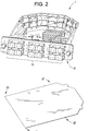
- FIG. 2 is an isometric view of a cable adaptor case 1 that does not form part of the invention and an isometric view of a lid 21 that does not form part of the invention.
- the cable adaptor tray 11 may have any variety of a plurality of adaptors.
- a plurality of adaptors 13 may be embedded in the adaptor tray 11.
- the plurality of adaptors 13 shown in FIG. 2a are different from the plurality of adaptors 12 of FIG. 1 .
- the adaptor tray 11 may be an industry standard LGX 118 panel.
- the lid 21 comprises a plurality of snaps 25, which are removably attached to the cable tray 2, and a plurality of hinges 23, which are removably attached and hingeably attached to the cable tray 2.
- the tray 21 of FIG. 2 shows two hinges 23 and two snaps 25.
- FIG. 3 is an overhead view of a cable tray 2 that does not form part of the invention.
- the cable tray 2 includes a plurality of bridges 5 for securing a plurality of cables, a splice holder 7 for holding spliced cables, a plurality of splice slots 8 for holding the splice holder 7, a plurality of hooks 9 to secure a plurality of cables, a plurality of breakout portions 10, and a plurality of towers 14 for sorting a plurality of cables.
- the splice holder 7 may be made of plastic and may have a plurality of rows which has a plurality of divots for receiving the spliced cables.
- the plurality of rows may be stacked on top of one another and fit into the plurality of splice holders 8 for securing the spliced cables.
- the plurality of breakout portions 10 may be broken by an operator to allow for entry of a plurality of cables into the cable tray 2.
- a plurality of cables may enter from various positions into the cable tray 2 depending upon which one of the plurality of breakout portions is broken by an operator.
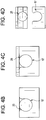
- FIG. 4a is a side view of a cable tray 2 that does not form part of the invention comprising a lid 21. Both the plurality of snaps 25 and the plurality of hinges 23 are removably attached to a plurality of receivers 17 in the cable tray 2. In an exemplary embodiment, the plurality of hinges are removably attached to the cable tray 2.
- FIG. 4b is a close-up side view of a cable tray 2 that does not form part of the invention with a hinge 23 removably attached to a receiver 17 of the cable tray 2.
- FIG. 4c is a close-up side view of a cable tray 2 that does not form part of the invention with a snap 25 removably attached to a receiver 17 of the cable tray 2.
- FIG. 4d is a close-up side view of a cable tray 2 that does not form part of the invention with a snap 25 removed from a receiver 17 of the cable tray 2.
- FIG. 5 is an isometric view of a cable tray 2 that does not form part of the invention with a lid 21 and an adaptor plate 11.
- the lid 21 is shown to be hingeably attached by the plurality of hinges 23 to the plurality of receivers 17 of the cable tray 2.
- the snaps 25 are removed from the plurality of receivers 17.
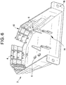
- FIG. 6 is an isometric view of a cable tray 2 that does not form part of the invention wherein a lid 21 and an adaptor plate 11 are not attached. As shown in FIG. 6 , one of the plurality of breakout portions 10 is removed. An adaptor plate 11 may be attached to a plurality of adaptor plate receivers 16 of the cable tray 2. In addition, the plurality of steps 3 of the cable tray 2 has a plurality of holes 4. In an exemplary embodiment, a plurality of cables may be attached to the plurality of steps 3 by using a zip-tie, which is fed through the plurality of holes 4, to wrap around the plurality of cables.
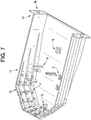
- FIG. 7 is an isometric view of a cable tray 2 that does not form part of the invention wherein a lid 21 and an adaptor plate 11 are not attached. Additional hooks 9 may be formed in a position away from the plurality of steps 3.
- FIG. 8 is an isometric view of an exemplary embodiment of a cable tray 29, wherein a lid 60 has receiving sections 62, and the cable tray 29 including protruding sections 30.
- the protruding sections 30 interact with the receiving sections 62 so that the lid 60 is removably attached to the cable tray 29.
- the lid 60 may be removed by sliding the lid 60 away from the plurality of adaptors 52.
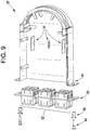
- FIG. 9 is an isometric view of an exemplary embodiment of a cable tray 29 and an adaptor tray 50 detached from the cable tray 29.
- a plurality of screws 54 removably attach to a plurality of screw adaptors 56 for removably attaching the adaptor plate 50 to a plurality of screw receivers 44.
- An exemplary embodiment of a plurality of splice slots 31 is provided in the cable tray 29.
- the splice slots 31 in FIG. 9 are configured for holding two splice holders 32.
- FIG. 10 is an isometric view of an exemplary embodiment of a cable tray 29 and an exemplary embodiment of a splice holder 32 detached from the cable tray 29.
- the splice holder 32 has a splice sorter 35 for holding and sorting cables which have been spliced, a splice holder adaptor 37 for adapting the splice sorter 35 to be removably attached to the splice slots 31, and a splice cap 33 for protecting the wires in the splice sorter 35 and for covering the splice sorter 35.
- the splice sorter 35 of FIG. 10 is made of one piece of plastic, as opposed to a plurality of rows of the splice holder 7 of FIG. 3 .
- the splice sorter can hold up to 24 spliced wires.
- the splice holder 32 can hold both single fusion and ribbon splice sleeves.
- the splice holder 32 provides a secure mounting area for splices (i.e. splices will not pop out).
- the splice holder 32 is removable by a "snap-in/snap-out" feature. This feature makes installation easier since splice sleeves can be loaded into the splice sleeve holder outside of the patch and splice module.
- the cable tray 29 has a cable clip 39 for holding cables.
- FIG. 11 is an isometric view of an exemplary embodiment of a cable tray 29 wherein a plurality of splice holders 32 and a plurality of cable clips 39 interact with the cable tray 29.
- two splice holders 32 are shown to be removably attached to the splice slots 31.
- the cable clips 39 are shown to be removably attached to the cable tray 29.
- the cable clips 39 secure a plurality of cables which exit the cable tray 29.
- the cable tray 29 allows a plurality of cables to enter into the back of the module across a 180 degree sweep.
- the back of the cable tray 29 consists of a tiered semicircular geometry that allows fiber optic cable to enter into two, separate entry ports.
- FIG. 12 is an isometric section view of an exemplary embodiment of a cable tray 29 with a lid 60 removably attached to the cable tray 29.
- the cable tray 29 has a plurality of steps 42 for securing a plurality of cables.
- the cables exit the cable tray 29 and are secured on the plurality of steps 42 in a direction of the plurality of steps 42.
- An exemplary embodiment of the design of the cable clips 39 provides adequate pull tension while minimizing the time of installation.
- the clips 39 can be manufactured from semi-rigid plastic or rubber type materials to provide adequate amount of grip to the various types of tubing materials used to house the plurality of cables.
- An exemplary embodiment of the invention utilizes a lid 60 that slides and snaps into place maintaining the compression of the clips 39 and maintaining integrity.
- the lid 60 can optionally be hinged to provide access without removal of the lid 60.
Landscapes
- Physics & Mathematics (AREA)
- General Physics & Mathematics (AREA)
- Optics & Photonics (AREA)
- Light Guides In General And Applications Therefor (AREA)
- Cable Accessories (AREA)
Description
- The invention relates to a cable adaptor case, and more particularly to a cable adapter case for sorting cables.
- Existing patch and splice cassette modules are not space-efficient. Most offerings on the market do not conform to the standard LGX118 footprint. The most popular offerings utilize multi-component assemblies which can be cumbersome from a fiber management standpoint. Existing technology uses moving parts which can place the fiber at risk for damage. Current offerings require tie-wraps to secure incoming cable. This approach is very time-consuming and requires multiple consumable items.
- Current patch and splice modules offer one of two options: 1) a stationary splice sleeve holder that cannot be removed from the module. This makes installation very difficult because it is much easier to mount the splices into the splice sleeve holder when it is not inside of the module (not much hand room inside the module). 2) an open splice sleeve holder that can be removed from the module. This can pose problems because splice sleeves can easily fall out of conventional splice sleeve holders. This is because such splice sleeve holders are made out of flimsy rubber that bends when being mounted into or removed from the patch and splice module. When this rubber bends the splice sleeves can easily pop out which in turn increases the time of installation and even can lead to fiber damage.
- Other disadvantages and limitations include: (1) Cable entry/access is limited; (2) Cables coming into the module can only enter in through certain directions/angles/entry ports; (3) Traditional patch and splice modules do not do a good job of managing ribbon fiber; and (4) Existing cassette modules accept proprietary or custom sized adapter plates.
-
US 2012/134639 relates to relates to a fiber optic module such as a splice module that includes at least one entry opening for cable or optical fiber ingress and/or egress that is disposed on the same side as an adapter plate. - Exemplary implementations of the present invention address at least the above problems and/or disadvantages and other disadvantages not described above. Also, the present invention is not required to overcome the disadvantages described above, and an exemplary implementation of the present invention may not overcome any of the problems listed above.
- One embodiment of the present invention utilizes a cable adaptor case including a cable tray configured to hold a plurality of cables, and an adaptor tray removably attached to the cable tray. The back of the cable tray comprises a plurality of steps configured to hold the plurality of cables. The cable adaptor case includes a plurality of cable clips removably attached to the cable tray and configured to secure the plurality of cables to the cable tray. The cable adaptor case also includes a lid removably attached to the cable tray, the lid being configured to snap into place and maintain compression of the plurality of cable clips. The adaptor tray includes a plurality of adaptors to connect the plurality of cables.
- Other features of the embodiment may include the cable tray with a plurality of splice holders configured to hold spliced cables. Other features of the embodiments include a plurality of splice slots configured to hold the plurality of splice holders.
- Another embodiment of the invention may include the plurality of splice holders having a splice sorter configured to hold and sort the spliced cables, a splice holder adaptor configured to hold the splice sorter to be removably attached to the splice slots, and a splice cap configured to cover the spliced cables in the splice sorter and the splice sorter.
- Other features of the embodiment may include the plurality of steps having removable breakout portions through which the plurality of cables enter the cable tray.
- Other features of the embodiment may include the plurality of steps having a plurality of holes for attaching the plurality of cables to the plurality of steps.
- Another embodiment of the invention may include the cable tray having a plurality of receivers for receiving the lid.
- Other features of the embodiment may include the lid having a plurality of snaps configured to be removably attached to the receivers of the cable tray, and a plurality of hinges configured to be hingably attached and removably attached to the receivers of the cable tray.
- Other features of the embodiment may include the cable tray having a plurality of hooks configured to secure the plurality of cables to the cable tray.
- Other features of the embodiment may include the cable tray having a plurality of towers configured to sort and organize the plurality of cables.
- Other features of the embodiment may include the cable tray having a plurality of screw receivers opposite the plurality of steps configured to receive the adaptor plate.
- Another embodiment of the invention may include a plurality of screws removably attached to a plurality of screw adaptors for removably attaching the adaptor plate to the plurality of screw receivers.
-
-
FIG. 1 is an isometric view of acable adaptor case 1 that does not form part of the invention. -
FIG. 2 is an isometric view of acable adaptor case 1 that does not form part of the invention and an isometric view of an exemplary embodiment of alid 21 that does not form part of the invention. -
FIG. 3 is an overhead view of acable tray 2 that does not form part of the invention. -
FIG. 4a is a side view of acable tray 2 that does not form part of the invention comprising alid 21. -
FIG. 4b is a close-up side view of acable tray 2 that does not form part of the invention comprising ahinge 23 removably attached to areceiver 17 of thecable tray 2. -
FIG. 4c is a close-up side view of acable tray 2 that does not form part of the invention comprising atab 25 removably attached to areceiver 17 of thecable tray 2. -
FIG. 4d is a close-up side view of acable tray 2 that does not form part of the invention comprising atab 25 removed from areceiver 17 of thecable tray 2. -
FIG. 5 is an isometric view of acable tray 2 that does not form part of the invention comprising alid 21 hingably attached to thecable tray 2 and anadaptor plate 11. -
FIG. 6 is an isometric view of acable tray 2 that does not form part of the invention wherein alid 21 and anadaptor plate 11 are not attached. -
FIG. 7 is an isometric view of acable tray 2 that does not form part of the invention wherein alid 21 and anadaptor plate 11 are not attached. -
FIG. 8 is an isometric view of an exemplary embodiment of acable tray 29 wherein alid 60 comprises receivingsections 29 and thecable tray 29 comprises protrudingsections 30. -
FIG. 9 is an isometric view of an exemplary embodiment of acable tray 2 and anadaptor tray 50 detached from thecable tray 29. -
FIG. 10 is an isometric view of an exemplary embodiment of acable tray 29 and an exemplary embodiment of asplice holder 32 detached from thecable tray 29. -
FIG. 11 is an isometric view of an exemplary embodiment of acable tray 29 wherein a plurality ofsplice holders 32 and a plurality ofcable clips 39 interact with thecable tray 29. -
FIG. 12 is an isometric section view of an exemplary embodiment of acable tray 29 with alid 60 removably attached to thecable tray 29. - The following detailed description is provided to assist the reader in gaining a comprehensive understanding of the methods, apparatuses and/or systems described herein. Various changes, modifications, and equivalents of the systems, apparatuses and/or methods described herein will suggest themselves to those of ordinary skill in the art. Descriptions of well-known functions and structures are omitted to enhance clarity and conciseness.
- The terms used in the description are intended to describe embodiments only, and shall by no means be restrictive. Unless clearly used otherwise, expressions in a singular from include a meaning of a plural form. In the present description, an expression such as "comprising" or "including" is intended to designate a characteristic, a number, a step, an operation, an element, a part or combinations thereof, and shall not be construed to preclude any presence or possibility of one or more other characteristics, numbers, steps, operations, elements, parts or combinations thereof.
- In an exemplary embodiment, the invention does not contain any moving parts (i.e.: hinges, etc). An advantage to this embodiment is simplicity - minimal number of parts involved. More specifically, an exemplary embodiment of the invention possesses four fundamental components to ensure simplicity: an adapter plate to assist with fiber optic interconnectivity, a body/lid to provide a protected environment for fiber optic components, a splice sleeve holder for the management and mounting of fiber optic splices, and a cable mounting clip for the time-efficient installation and mounting of fiber optic cable.
- Referring to the drawings,
FIG. 1 is an isometric view of acable adaptor case 1 that does not form part of the invention. Thecable adaptor case 1 includes acable tray 2 for holding a plurality of cables, anadaptor tray 11, and alid 21 which is removably attached and hingably attached to the cable tray. Thecable tray 2 has a plurality ofsteps 3 for holding a plurality of cables. Theadaptor tray 11 has a plurality ofadaptors 12 for connecting cables from inside thecable tray 2 to a set of cables outside of thecable tray 2. Theadaptor tray 11 is removably attached to thecable tray 2. The cable tray may be attached by ascrew 15. Theadapter case 1 may be made of metal, plastic, or other similar materials. -
FIG. 2 is an isometric view of acable adaptor case 1 that does not form part of the invention and an isometric view of alid 21 that does not form part of the invention. Thecable adaptor tray 11 may have any variety of a plurality of adaptors. A plurality ofadaptors 13 may be embedded in theadaptor tray 11. The plurality ofadaptors 13 shown inFIG. 2a are different from the plurality ofadaptors 12 ofFIG. 1 . Theadaptor tray 11 may be an industry standard LGX 118 panel. Thelid 21 comprises a plurality ofsnaps 25, which are removably attached to thecable tray 2, and a plurality ofhinges 23, which are removably attached and hingeably attached to thecable tray 2. Thetray 21 ofFIG. 2 shows twohinges 23 and twosnaps 25. -
FIG. 3 is an overhead view of acable tray 2 that does not form part of the invention. Thecable tray 2 includes a plurality ofbridges 5 for securing a plurality of cables, a splice holder 7 for holding spliced cables, a plurality ofsplice slots 8 for holding the splice holder 7, a plurality ofhooks 9 to secure a plurality of cables, a plurality ofbreakout portions 10, and a plurality oftowers 14 for sorting a plurality of cables. The splice holder 7 may be made of plastic and may have a plurality of rows which has a plurality of divots for receiving the spliced cables. Once the plurality of divots have received the spliced cables, the plurality of rows may be stacked on top of one another and fit into the plurality ofsplice holders 8 for securing the spliced cables. The plurality ofbreakout portions 10 may be broken by an operator to allow for entry of a plurality of cables into thecable tray 2. A plurality of cables may enter from various positions into thecable tray 2 depending upon which one of the plurality of breakout portions is broken by an operator. -
FIG. 4a is a side view of acable tray 2 that does not form part of the invention comprising alid 21. Both the plurality ofsnaps 25 and the plurality ofhinges 23 are removably attached to a plurality ofreceivers 17 in thecable tray 2. In an exemplary embodiment, the plurality of hinges are removably attached to thecable tray 2. -
FIG. 4b is a close-up side view of acable tray 2 that does not form part of the invention with ahinge 23 removably attached to areceiver 17 of thecable tray 2. -
FIG. 4c is a close-up side view of acable tray 2 that does not form part of the invention with asnap 25 removably attached to areceiver 17 of thecable tray 2. -
FIG. 4d is a close-up side view of acable tray 2 that does not form part of the invention with asnap 25 removed from areceiver 17 of thecable tray 2. -
FIG. 5 is an isometric view of acable tray 2 that does not form part of the invention with alid 21 and anadaptor plate 11. Thelid 21 is shown to be hingeably attached by the plurality ofhinges 23 to the plurality ofreceivers 17 of thecable tray 2. Thesnaps 25 are removed from the plurality ofreceivers 17. -
FIG. 6 is an isometric view of acable tray 2 that does not form part of the invention wherein alid 21 and anadaptor plate 11 are not attached. As shown inFIG. 6 , one of the plurality ofbreakout portions 10 is removed. Anadaptor plate 11 may be attached to a plurality ofadaptor plate receivers 16 of thecable tray 2. In addition, the plurality ofsteps 3 of thecable tray 2 has a plurality ofholes 4. In an exemplary embodiment, a plurality of cables may be attached to the plurality ofsteps 3 by using a zip-tie, which is fed through the plurality ofholes 4, to wrap around the plurality of cables. -
FIG. 7 is an isometric view of acable tray 2 that does not form part of the invention wherein alid 21 and anadaptor plate 11 are not attached.Additional hooks 9 may be formed in a position away from the plurality ofsteps 3. -
FIG. 8 is an isometric view of an exemplary embodiment of acable tray 29, wherein alid 60 has receivingsections 62, and thecable tray 29 including protrudingsections 30. In an exemplary embodiment, the protrudingsections 30 interact with the receivingsections 62 so that thelid 60 is removably attached to thecable tray 29. In an exemplary embodiment, thelid 60 may be removed by sliding thelid 60 away from the plurality ofadaptors 52. -
FIG. 9 is an isometric view of an exemplary embodiment of acable tray 29 and anadaptor tray 50 detached from thecable tray 29. In an exemplary embodiment, a plurality ofscrews 54 removably attach to a plurality ofscrew adaptors 56 for removably attaching theadaptor plate 50 to a plurality ofscrew receivers 44. An exemplary embodiment of a plurality ofsplice slots 31 is provided in thecable tray 29. Thesplice slots 31 inFIG. 9 are configured for holding twosplice holders 32. -
FIG. 10 is an isometric view of an exemplary embodiment of acable tray 29 and an exemplary embodiment of asplice holder 32 detached from thecable tray 29. In an exemplary embodiment, thesplice holder 32 has asplice sorter 35 for holding and sorting cables which have been spliced, asplice holder adaptor 37 for adapting thesplice sorter 35 to be removably attached to thesplice slots 31, and asplice cap 33 for protecting the wires in thesplice sorter 35 and for covering thesplice sorter 35. In an exemplary embodiment, thesplice sorter 35 ofFIG. 10 is made of one piece of plastic, as opposed to a plurality of rows of the splice holder 7 ofFIG. 3 . - In an exemplary embodiment, as shown in
FIG. 10 , the splice sorter can hold up to 24 spliced wires. In an exemplary embodiment, thesplice holder 32 can hold both single fusion and ribbon splice sleeves. In an exemplary embodiment, thesplice holder 32 provides a secure mounting area for splices (i.e. splices will not pop out). In an exemplary embodiment, thesplice holder 32 is removable by a "snap-in/snap-out" feature. This feature makes installation easier since splice sleeves can be loaded into the splice sleeve holder outside of the patch and splice module. In an exemplary embodiment, as shown inFIG. 10 , thecable tray 29 has acable clip 39 for holding cables. -
FIG. 11 is an isometric view of an exemplary embodiment of acable tray 29 wherein a plurality ofsplice holders 32 and a plurality of cable clips 39 interact with thecable tray 29. In an exemplary embodiment, twosplice holders 32 are shown to be removably attached to thesplice slots 31. In an exemplary embodiment, the cable clips 39 are shown to be removably attached to thecable tray 29. In an exemplary embodiment, the cable clips 39 secure a plurality of cables which exit thecable tray 29. In an exemplary embodiment, thecable tray 29 allows a plurality of cables to enter into the back of the module across a 180 degree sweep. In a more specific exemplary embodiment, the back of thecable tray 29 consists of a tiered semicircular geometry that allows fiber optic cable to enter into two, separate entry ports. -
FIG. 12 is an isometric section view of an exemplary embodiment of acable tray 29 with alid 60 removably attached to thecable tray 29. In an exemplary embodiment, thecable tray 29 has a plurality ofsteps 42 for securing a plurality of cables. In an exemplary embodiment, once the cable clips 39 have secured the plurality of cables, the cables exit thecable tray 29 and are secured on the plurality ofsteps 42 in a direction of the plurality ofsteps 42. An exemplary embodiment of the design of the cable clips 39 provides adequate pull tension while minimizing the time of installation. In an exemplary embodiment, theclips 39 can be manufactured from semi-rigid plastic or rubber type materials to provide adequate amount of grip to the various types of tubing materials used to house the plurality of cables. An exemplary embodiment of the invention utilizes alid 60 that slides and snaps into place maintaining the compression of theclips 39 and maintaining integrity. In an exemplary embodiment, thelid 60 can optionally be hinged to provide access without removal of thelid 60. - As mentioned above, the embodiments described above are merely exemplary and the general inventive concept should not be limited thereto.
Claims (12)
- A cable adaptor case (1) comprising:a cable tray (29) configured to hold a plurality of cables; andan adaptor tray (50) removably attached to the cable tray,wherein a back of the cable tray comprises a plurality of steps (42) configured to hold the plurality of cables;a plurality of cable clips (39) removably attached to the cable tray and configured to secure the plurality of cables to the cable tray;a lid (60) removably attached to the cable tray, the lid being configured to snap into place and maintain compression of the plurality of cable clips; andwherein the adaptor tray comprises a plurality of adaptors (52) configured to connect the plurality of cables.
- The cable adaptor case of claim 1, wherein the cable tray further comprises a plurality of splice holders (32) configured to hold spliced cables.
- The cable adaptor case of claim 2, wherein the cable tray further comprises a plurality of splice slots (31) configured to hold the plurality of splice holders.
- The cable adaptor case of claim 3, wherein the plurality of splice holders further comprises:a splice sorter (35) configured to hold and sort the spliced cables;a splice holder adaptor (37) configured to hold the splice sorter to be removably attached to the splice slots; anda splice cap (33) configured to cover the spliced cables in the splice sorter and the splice sorter.
- The cable adaptor case of claim 1, wherein the plurality of steps comprises a plurality of removable breakout portions (10) through which the plurality of cables enter the cable tray.
- The cable adaptor case of claim 5, wherein the plurality of steps comprises a plurality of holes (4) for attaching the plurality of cables to the plurality of steps.
- The cable adaptor case of claim 1, wherein the cable tray further comprises a plurality of receivers (17) for receiving the lid.
- The cable adaptor case of claim 7, wherein the lid further comprises a plurality of snaps (25) configured to be removably attached to the receivers of the cable tray, and a plurality of hinges (23) configured to be hingably attached and removably attached to the receivers of the cable tray.
- The cable adaptor case of claim 1, wherein the cable tray further comprises a plurality of hooks (9) configured to secure the plurality of cables to the cable tray.
- The cable adaptor case of claim 1, wherein the cable tray further comprises a plurality of towers (14) configured to sort and organize the plurality of cables.
- The cable adaptor case of claim 1, wherein the cable tray further comprises a plurality of screw receivers (44) opposite the plurality of steps configured to receive the adaptor plate.
- The cable adaptor case of claim 11, wherein a plurality of screws are removably attached to a plurality of screw adaptors (56) for removably attaching the adaptor plate to the plurality of screw receivers.
Priority Applications (1)
| Application Number | Priority Date | Filing Date | Title |
|---|---|---|---|
| EP19193178.1A EP3591444A1 (en) | 2012-09-28 | 2013-09-30 | Field installable optical module with configurable cable attachment and internal cable management features |
Applications Claiming Priority (3)
| Application Number | Priority Date | Filing Date | Title |
|---|---|---|---|
| US201261707643P | 2012-09-28 | 2012-09-28 | |
| US201361762488P | 2013-02-08 | 2013-02-08 | |
| PCT/US2013/062631 WO2014052963A1 (en) | 2012-09-28 | 2013-09-30 | Field installable optical module with cable attachment |
Related Child Applications (2)
| Application Number | Title | Priority Date | Filing Date |
|---|---|---|---|
| EP19193178.1A Division-Into EP3591444A1 (en) | 2012-09-28 | 2013-09-30 | Field installable optical module with configurable cable attachment and internal cable management features |
| EP19193178.1A Division EP3591444A1 (en) | 2012-09-28 | 2013-09-30 | Field installable optical module with configurable cable attachment and internal cable management features |
Publications (3)
| Publication Number | Publication Date |
|---|---|
| EP2888617A1 EP2888617A1 (en) | 2015-07-01 |
| EP2888617A4 EP2888617A4 (en) | 2016-04-20 |
| EP2888617B1 true EP2888617B1 (en) | 2019-11-06 |
Family
ID=50389053
Family Applications (2)
| Application Number | Title | Priority Date | Filing Date |
|---|---|---|---|
| EP13841228.3A Active EP2888617B1 (en) | 2012-09-28 | 2013-09-30 | Field installable optical module with configurable cable attachment and internal cable management features |
| EP19193178.1A Withdrawn EP3591444A1 (en) | 2012-09-28 | 2013-09-30 | Field installable optical module with configurable cable attachment and internal cable management features |
Family Applications After (1)
| Application Number | Title | Priority Date | Filing Date |
|---|---|---|---|
| EP19193178.1A Withdrawn EP3591444A1 (en) | 2012-09-28 | 2013-09-30 | Field installable optical module with configurable cable attachment and internal cable management features |
Country Status (6)
| Country | Link |
|---|---|
| US (2) | US10048460B2 (en) |
| EP (2) | EP2888617B1 (en) |
| AU (1) | AU2013323161B2 (en) |
| CA (1) | CA2886637C (en) |
| MX (1) | MX343170B (en) |
| WO (1) | WO2014052963A1 (en) |
Cited By (2)
| Publication number | Priority date | Publication date | Assignee | Title |
|---|---|---|---|---|
| US11740421B2 (en) | 2021-02-18 | 2023-08-29 | Commscope Technologies Llc | Communications panel system |
| US11971598B2 (en) | 2021-02-18 | 2024-04-30 | Commscope Technologies Llc | Tray arrangements for cassettes |
Families Citing this family (16)
| Publication number | Priority date | Publication date | Assignee | Title |
|---|---|---|---|---|
| US9823432B2 (en) | 2013-03-19 | 2017-11-21 | Adc Czech Republic, S.R.O. | Moveable bend control and patch cord support for telecommunications panel |
| CN107076953B (en) | 2014-09-16 | 2020-05-15 | 康普连通比利时私人有限公司 | Multi-position telecommunications carrier |
| NZ762104A (en) | 2014-09-16 | 2022-12-23 | CommScope Connectivity Belgium BVBA | Telecommunications tray with a cable routing path extending through a pivot hinge |
| EP4398018A3 (en) | 2014-09-16 | 2024-09-18 | CommScope Connectivity Belgium BVBA | Telecommunications tray assembly |
| EP3286588B1 (en) | 2015-04-23 | 2020-01-29 | CommScope Connectivity Belgium BVBA | Telecommunications panel assembly with movable adapters |
| EP3583456A1 (en) | 2017-02-15 | 2019-12-25 | CommScope Connectivity Belgium BVBA | Modular telecommunications enclosures |
| CN107102403A (en) * | 2017-05-19 | 2017-08-29 | 宁波日鼎电子科技有限公司 | A kind of welding adapter of fibre-optical splice protection |
| WO2019025010A1 (en) * | 2017-08-04 | 2019-02-07 | Prysmian S.P.A. | OPTICAL DISTRIBUTION BOX |
| EP3701304B1 (en) | 2017-10-26 | 2022-05-04 | CommScope Connectivity Belgium BVBA | Telecommunications system |
| EP4509895A3 (en) * | 2018-05-14 | 2025-06-18 | AFL Telecommunications LLC | Butt closures and organizer assemblies therefor |
| US11048055B2 (en) | 2018-11-16 | 2021-06-29 | Panduit Corp. | Fiber optic cassette |
| EP3745177A1 (en) * | 2019-05-29 | 2020-12-02 | CommScope Technologies LLC | Fiber optic holder tray adapter; assembly; and method |
| US10845561B1 (en) * | 2019-06-28 | 2020-11-24 | Afl Telecommunications Llc | Fiber optic cassettes and splice modules |
| EP4038431A4 (en) | 2019-09-30 | 2023-11-01 | CommScope Technologies LLC | OPTICAL PLATE ASSEMBLIES AND MODULES THEREOF |
| US11927808B2 (en) | 2021-04-16 | 2024-03-12 | Commscope Technologies Llc | Holder for an optical component |
| US12158628B2 (en) | 2022-10-28 | 2024-12-03 | Panduit Corp. | Multi-work area fiber module |
Family Cites Families (11)
| Publication number | Priority date | Publication date | Assignee | Title |
|---|---|---|---|---|
| GB9318654D0 (en) | 1993-09-08 | 1993-10-27 | Raychem Sa Nv | Optical fibre organizer |
| WO1996010203A1 (en) * | 1994-09-28 | 1996-04-04 | Telephone Cables Limited | A splice tray |
| US20060067636A1 (en) * | 2004-09-24 | 2006-03-30 | 3M Innovative Properties Company | Connector and splice holder device |
| US8472772B2 (en) * | 2006-06-22 | 2013-06-25 | Prysmian Cables & Systems Limited | Cable loop device for optical systems |
| US7463812B2 (en) * | 2007-01-19 | 2008-12-09 | Adc Telecommunications, Inc. | Overhead cable termination arrangement |
| US7945138B2 (en) * | 2007-10-01 | 2011-05-17 | Clearfield, Inc. | Modular optical fiber cassette |
| US7751674B2 (en) * | 2007-10-01 | 2010-07-06 | Clearfield, Inc. | Modular optical fiber cassettes and fiber management methods |
| US8860676B2 (en) * | 2010-01-26 | 2014-10-14 | Panasonic Intellectual Property Corporation Of America | Display control device, method, program, and integrated circuit |
| US20120134639A1 (en) * | 2010-11-30 | 2012-05-31 | Giraud William J | Module with adapter side entry opening |
| WO2011163464A2 (en) * | 2010-06-23 | 2011-12-29 | Adc Telecommunications, Inc. | Telecommunications assembly |
| GB2488359B (en) * | 2011-02-25 | 2015-06-24 | Flex Connectors Ltd | A modular electrical connection unit |
-
2013
- 2013-09-30 AU AU2013323161A patent/AU2013323161B2/en active Active
- 2013-09-30 EP EP13841228.3A patent/EP2888617B1/en active Active
- 2013-09-30 MX MX2015003857A patent/MX343170B/en active IP Right Grant
- 2013-09-30 EP EP19193178.1A patent/EP3591444A1/en not_active Withdrawn
- 2013-09-30 US US14/430,645 patent/US10048460B2/en active Active
- 2013-09-30 CA CA2886637A patent/CA2886637C/en active Active
- 2013-09-30 WO PCT/US2013/062631 patent/WO2014052963A1/en not_active Ceased
-
2018
- 2018-08-13 US US16/101,975 patent/US10613286B2/en active Active
Non-Patent Citations (1)
| Title |
|---|
| None * |
Cited By (4)
| Publication number | Priority date | Publication date | Assignee | Title |
|---|---|---|---|---|
| US11740421B2 (en) | 2021-02-18 | 2023-08-29 | Commscope Technologies Llc | Communications panel system |
| US11971598B2 (en) | 2021-02-18 | 2024-04-30 | Commscope Technologies Llc | Tray arrangements for cassettes |
| US12416771B2 (en) | 2021-02-18 | 2025-09-16 | Commscope Technologies Llc | Tray arrangements for cassettes |
| US12468107B2 (en) | 2021-02-18 | 2025-11-11 | Commscope Technologies Llc | Communications panel system |
Also Published As
| Publication number | Publication date |
|---|---|
| MX343170B (en) | 2016-10-26 |
| US20180348462A1 (en) | 2018-12-06 |
| US20150234142A1 (en) | 2015-08-20 |
| EP2888617A1 (en) | 2015-07-01 |
| MX2015003857A (en) | 2015-07-17 |
| US10613286B2 (en) | 2020-04-07 |
| AU2013323161B2 (en) | 2017-06-22 |
| CA2886637C (en) | 2021-01-12 |
| EP3591444A1 (en) | 2020-01-08 |
| WO2014052963A1 (en) | 2014-04-03 |
| EP2888617A4 (en) | 2016-04-20 |
| US10048460B2 (en) | 2018-08-14 |
| CA2886637A1 (en) | 2014-04-03 |
| AU2013323161A1 (en) | 2015-04-09 |
Similar Documents
| Publication | Publication Date | Title |
|---|---|---|
| US10613286B2 (en) | Field installable optical module with configurable cable attachment | |
| US10718919B2 (en) | Field-installable optical module with configurable cable attachment and internal cable management features | |
| US10082635B2 (en) | Fiber splice and distribution module and fiber splice and distribution frame | |
| CA2832288C (en) | Optical fiber cable drop interface box | |
| US8660397B2 (en) | Multi-layer module | |
| US7333706B2 (en) | Enclosure and organizer for telecommunication lines and splices | |
| US8385711B2 (en) | Multi-configurable splice holder | |
| CN101384937B (en) | Fiber distribution hub with swing frame and modular termination panels | |
| US20120134639A1 (en) | Module with adapter side entry opening | |
| US20060098932A1 (en) | Optical connection closure having at least one connector port | |
| US9279950B2 (en) | Exterior distribution pedestal cabinet | |
| CN106687841A (en) | Cable distribution system | |
| WO2018217461A1 (en) | Mechanical cable entry port | |
| US20060193588A1 (en) | Fiber access terminal | |
| CN103069836A (en) | Telecommunications assembly | |
| US7308183B2 (en) | Fiber access terminal including moisture barrier plate | |
| CA3041923A1 (en) | Splicing and termination tray, distribution frame, and fiber distribution terminal | |
| WO2020205188A1 (en) | Fiber optic splice tray |
Legal Events
| Date | Code | Title | Description |
|---|---|---|---|
| PUAI | Public reference made under article 153(3) epc to a published international application that has entered the european phase |
Free format text: ORIGINAL CODE: 0009012 |
|
| 17P | Request for examination filed |
Effective date: 20150325 |
|
| AK | Designated contracting states |
Kind code of ref document: A1 Designated state(s): AL AT BE BG CH CY CZ DE DK EE ES FI FR GB GR HR HU IE IS IT LI LT LU LV MC MK MT NL NO PL PT RO RS SE SI SK SM TR |
|
| AX | Request for extension of the european patent |
Extension state: BA ME |
|
| DAX | Request for extension of the european patent (deleted) | ||
| RA4 | Supplementary search report drawn up and despatched (corrected) |
Effective date: 20160317 |
|
| RIC1 | Information provided on ipc code assigned before grant |
Ipc: G02B 6/00 20060101AFI20160311BHEP Ipc: G02B 6/36 20060101ALI20160311BHEP Ipc: G02B 6/42 20060101ALI20160311BHEP |
|
| RIC1 | Information provided on ipc code assigned before grant |
Ipc: G02B 6/44 20060101ALI20170228BHEP Ipc: G02B 6/42 20060101ALI20170228BHEP Ipc: G02B 6/36 20060101ALI20170228BHEP Ipc: G02B 6/00 20060101AFI20170228BHEP |
|
| STAA | Information on the status of an ep patent application or granted ep patent |
Free format text: STATUS: EXAMINATION IS IN PROGRESS |
|
| 17Q | First examination report despatched |
Effective date: 20170512 |
|
| RIC1 | Information provided on ipc code assigned before grant |
Ipc: G02B 6/42 20060101ALI20180420BHEP Ipc: G02B 6/36 20060101ALI20180420BHEP Ipc: G02B 6/38 20060101ALI20180420BHEP Ipc: G02B 6/44 20060101ALI20180420BHEP Ipc: G02B 6/00 20060101AFI20180420BHEP |
|
| GRAP | Despatch of communication of intention to grant a patent |
Free format text: ORIGINAL CODE: EPIDOSNIGR1 |
|
| STAA | Information on the status of an ep patent application or granted ep patent |
Free format text: STATUS: GRANT OF PATENT IS INTENDED |
|
| INTG | Intention to grant announced |
Effective date: 20190423 |
|
| GRAS | Grant fee paid |
Free format text: ORIGINAL CODE: EPIDOSNIGR3 |
|
| GRAA | (expected) grant |
Free format text: ORIGINAL CODE: 0009210 |
|
| STAA | Information on the status of an ep patent application or granted ep patent |
Free format text: STATUS: THE PATENT HAS BEEN GRANTED |
|
| AK | Designated contracting states |
Kind code of ref document: B1 Designated state(s): AL AT BE BG CH CY CZ DE DK EE ES FI FR GB GR HR HU IE IS IT LI LT LU LV MC MK MT NL NO PL PT RO RS SE SI SK SM TR |
|
| REG | Reference to a national code |
Ref country code: GB Ref legal event code: FG4D |
|
| REG | Reference to a national code |
Ref country code: CH Ref legal event code: EP Ref country code: AT Ref legal event code: REF Ref document number: 1199540 Country of ref document: AT Kind code of ref document: T Effective date: 20191115 |
|
| REG | Reference to a national code |
Ref country code: IE Ref legal event code: FG4D |
|
| REG | Reference to a national code |
Ref country code: DE Ref legal event code: R096 Ref document number: 602013062685 Country of ref document: DE |
|
| REG | Reference to a national code |
Ref country code: NL Ref legal event code: MP Effective date: 20191106 |
|
| REG | Reference to a national code |
Ref country code: LT Ref legal event code: MG4D |
|
| PG25 | Lapsed in a contracting state [announced via postgrant information from national office to epo] |
Ref country code: BG Free format text: LAPSE BECAUSE OF FAILURE TO SUBMIT A TRANSLATION OF THE DESCRIPTION OR TO PAY THE FEE WITHIN THE PRESCRIBED TIME-LIMIT Effective date: 20200206 Ref country code: FI Free format text: LAPSE BECAUSE OF FAILURE TO SUBMIT A TRANSLATION OF THE DESCRIPTION OR TO PAY THE FEE WITHIN THE PRESCRIBED TIME-LIMIT Effective date: 20191106 Ref country code: GR Free format text: LAPSE BECAUSE OF FAILURE TO SUBMIT A TRANSLATION OF THE DESCRIPTION OR TO PAY THE FEE WITHIN THE PRESCRIBED TIME-LIMIT Effective date: 20200207 Ref country code: NO Free format text: LAPSE BECAUSE OF FAILURE TO SUBMIT A TRANSLATION OF THE DESCRIPTION OR TO PAY THE FEE WITHIN THE PRESCRIBED TIME-LIMIT Effective date: 20200206 Ref country code: LV Free format text: LAPSE BECAUSE OF FAILURE TO SUBMIT A TRANSLATION OF THE DESCRIPTION OR TO PAY THE FEE WITHIN THE PRESCRIBED TIME-LIMIT Effective date: 20191106 Ref country code: PT Free format text: LAPSE BECAUSE OF FAILURE TO SUBMIT A TRANSLATION OF THE DESCRIPTION OR TO PAY THE FEE WITHIN THE PRESCRIBED TIME-LIMIT Effective date: 20200306 Ref country code: SE Free format text: LAPSE BECAUSE OF FAILURE TO SUBMIT A TRANSLATION OF THE DESCRIPTION OR TO PAY THE FEE WITHIN THE PRESCRIBED TIME-LIMIT Effective date: 20191106 Ref country code: NL Free format text: LAPSE BECAUSE OF FAILURE TO SUBMIT A TRANSLATION OF THE DESCRIPTION OR TO PAY THE FEE WITHIN THE PRESCRIBED TIME-LIMIT Effective date: 20191106 Ref country code: PL Free format text: LAPSE BECAUSE OF FAILURE TO SUBMIT A TRANSLATION OF THE DESCRIPTION OR TO PAY THE FEE WITHIN THE PRESCRIBED TIME-LIMIT Effective date: 20191106 Ref country code: LT Free format text: LAPSE BECAUSE OF FAILURE TO SUBMIT A TRANSLATION OF THE DESCRIPTION OR TO PAY THE FEE WITHIN THE PRESCRIBED TIME-LIMIT Effective date: 20191106 Ref country code: ES Free format text: LAPSE BECAUSE OF FAILURE TO SUBMIT A TRANSLATION OF THE DESCRIPTION OR TO PAY THE FEE WITHIN THE PRESCRIBED TIME-LIMIT Effective date: 20191106 |
|
| PG25 | Lapsed in a contracting state [announced via postgrant information from national office to epo] |
Ref country code: RS Free format text: LAPSE BECAUSE OF FAILURE TO SUBMIT A TRANSLATION OF THE DESCRIPTION OR TO PAY THE FEE WITHIN THE PRESCRIBED TIME-LIMIT Effective date: 20191106 Ref country code: HR Free format text: LAPSE BECAUSE OF FAILURE TO SUBMIT A TRANSLATION OF THE DESCRIPTION OR TO PAY THE FEE WITHIN THE PRESCRIBED TIME-LIMIT Effective date: 20191106 Ref country code: IS Free format text: LAPSE BECAUSE OF FAILURE TO SUBMIT A TRANSLATION OF THE DESCRIPTION OR TO PAY THE FEE WITHIN THE PRESCRIBED TIME-LIMIT Effective date: 20200306 |
|
| PG25 | Lapsed in a contracting state [announced via postgrant information from national office to epo] |
Ref country code: AL Free format text: LAPSE BECAUSE OF FAILURE TO SUBMIT A TRANSLATION OF THE DESCRIPTION OR TO PAY THE FEE WITHIN THE PRESCRIBED TIME-LIMIT Effective date: 20191106 |
|
| PG25 | Lapsed in a contracting state [announced via postgrant information from national office to epo] |
Ref country code: EE Free format text: LAPSE BECAUSE OF FAILURE TO SUBMIT A TRANSLATION OF THE DESCRIPTION OR TO PAY THE FEE WITHIN THE PRESCRIBED TIME-LIMIT Effective date: 20191106 Ref country code: DK Free format text: LAPSE BECAUSE OF FAILURE TO SUBMIT A TRANSLATION OF THE DESCRIPTION OR TO PAY THE FEE WITHIN THE PRESCRIBED TIME-LIMIT Effective date: 20191106 Ref country code: CZ Free format text: LAPSE BECAUSE OF FAILURE TO SUBMIT A TRANSLATION OF THE DESCRIPTION OR TO PAY THE FEE WITHIN THE PRESCRIBED TIME-LIMIT Effective date: 20191106 Ref country code: RO Free format text: LAPSE BECAUSE OF FAILURE TO SUBMIT A TRANSLATION OF THE DESCRIPTION OR TO PAY THE FEE WITHIN THE PRESCRIBED TIME-LIMIT Effective date: 20191106 |
|
| REG | Reference to a national code |
Ref country code: DE Ref legal event code: R097 Ref document number: 602013062685 Country of ref document: DE |
|
| REG | Reference to a national code |
Ref country code: AT Ref legal event code: MK05 Ref document number: 1199540 Country of ref document: AT Kind code of ref document: T Effective date: 20191106 |
|
| PG25 | Lapsed in a contracting state [announced via postgrant information from national office to epo] |
Ref country code: SM Free format text: LAPSE BECAUSE OF FAILURE TO SUBMIT A TRANSLATION OF THE DESCRIPTION OR TO PAY THE FEE WITHIN THE PRESCRIBED TIME-LIMIT Effective date: 20191106 Ref country code: SK Free format text: LAPSE BECAUSE OF FAILURE TO SUBMIT A TRANSLATION OF THE DESCRIPTION OR TO PAY THE FEE WITHIN THE PRESCRIBED TIME-LIMIT Effective date: 20191106 |
|
| PLBE | No opposition filed within time limit |
Free format text: ORIGINAL CODE: 0009261 |
|
| STAA | Information on the status of an ep patent application or granted ep patent |
Free format text: STATUS: NO OPPOSITION FILED WITHIN TIME LIMIT |
|
| 26N | No opposition filed |
Effective date: 20200807 |
|
| PG25 | Lapsed in a contracting state [announced via postgrant information from national office to epo] |
Ref country code: AT Free format text: LAPSE BECAUSE OF FAILURE TO SUBMIT A TRANSLATION OF THE DESCRIPTION OR TO PAY THE FEE WITHIN THE PRESCRIBED TIME-LIMIT Effective date: 20191106 Ref country code: SI Free format text: LAPSE BECAUSE OF FAILURE TO SUBMIT A TRANSLATION OF THE DESCRIPTION OR TO PAY THE FEE WITHIN THE PRESCRIBED TIME-LIMIT Effective date: 20191106 |
|
| PG25 | Lapsed in a contracting state [announced via postgrant information from national office to epo] |
Ref country code: IT Free format text: LAPSE BECAUSE OF FAILURE TO SUBMIT A TRANSLATION OF THE DESCRIPTION OR TO PAY THE FEE WITHIN THE PRESCRIBED TIME-LIMIT Effective date: 20191106 |
|
| PG25 | Lapsed in a contracting state [announced via postgrant information from national office to epo] |
Ref country code: MC Free format text: LAPSE BECAUSE OF FAILURE TO SUBMIT A TRANSLATION OF THE DESCRIPTION OR TO PAY THE FEE WITHIN THE PRESCRIBED TIME-LIMIT Effective date: 20191106 |
|
| REG | Reference to a national code |
Ref country code: CH Ref legal event code: PL |
|
| REG | Reference to a national code |
Ref country code: BE Ref legal event code: MM Effective date: 20200930 |
|
| PG25 | Lapsed in a contracting state [announced via postgrant information from national office to epo] |
Ref country code: LU Free format text: LAPSE BECAUSE OF NON-PAYMENT OF DUE FEES Effective date: 20200930 |
|
| PG25 | Lapsed in a contracting state [announced via postgrant information from national office to epo] |
Ref country code: LI Free format text: LAPSE BECAUSE OF NON-PAYMENT OF DUE FEES Effective date: 20200930 Ref country code: CH Free format text: LAPSE BECAUSE OF NON-PAYMENT OF DUE FEES Effective date: 20200930 Ref country code: BE Free format text: LAPSE BECAUSE OF NON-PAYMENT OF DUE FEES Effective date: 20200930 |
|
| PG25 | Lapsed in a contracting state [announced via postgrant information from national office to epo] |
Ref country code: TR Free format text: LAPSE BECAUSE OF FAILURE TO SUBMIT A TRANSLATION OF THE DESCRIPTION OR TO PAY THE FEE WITHIN THE PRESCRIBED TIME-LIMIT Effective date: 20191106 Ref country code: MT Free format text: LAPSE BECAUSE OF FAILURE TO SUBMIT A TRANSLATION OF THE DESCRIPTION OR TO PAY THE FEE WITHIN THE PRESCRIBED TIME-LIMIT Effective date: 20191106 Ref country code: CY Free format text: LAPSE BECAUSE OF FAILURE TO SUBMIT A TRANSLATION OF THE DESCRIPTION OR TO PAY THE FEE WITHIN THE PRESCRIBED TIME-LIMIT Effective date: 20191106 |
|
| PG25 | Lapsed in a contracting state [announced via postgrant information from national office to epo] |
Ref country code: MK Free format text: LAPSE BECAUSE OF FAILURE TO SUBMIT A TRANSLATION OF THE DESCRIPTION OR TO PAY THE FEE WITHIN THE PRESCRIBED TIME-LIMIT Effective date: 20191106 |
|
| PGFP | Annual fee paid to national office [announced via postgrant information from national office to epo] |
Ref country code: DE Payment date: 20250929 Year of fee payment: 13 |
|
| PGFP | Annual fee paid to national office [announced via postgrant information from national office to epo] |
Ref country code: GB Payment date: 20250929 Year of fee payment: 13 |
|
| PGFP | Annual fee paid to national office [announced via postgrant information from national office to epo] |
Ref country code: FR Payment date: 20250925 Year of fee payment: 13 |
|
| PGFP | Annual fee paid to national office [announced via postgrant information from national office to epo] |
Ref country code: IE Payment date: 20250929 Year of fee payment: 13 |
|
| REG | Reference to a national code |
Ref country code: DE Ref legal event code: R082 Ref document number: 602013062685 Country of ref document: DE Representative=s name: WESTPHAL, MUSSGNUG & PARTNER PATENTANWAELTE MI, DE |