EP2887879B1 - Ultraschallabbildungsverfahren - Google Patents
Ultraschallabbildungsverfahren Download PDFInfo
- Publication number
- EP2887879B1 EP2887879B1 EP13830423.3A EP13830423A EP2887879B1 EP 2887879 B1 EP2887879 B1 EP 2887879B1 EP 13830423 A EP13830423 A EP 13830423A EP 2887879 B1 EP2887879 B1 EP 2887879B1
- Authority
- EP
- European Patent Office
- Prior art keywords
- image
- data
- ultrasound
- echo data
- imaging
- Prior art date
- Legal status (The legal status is an assumption and is not a legal conclusion. Google has not performed a legal analysis and makes no representation as to the accuracy of the status listed.)
- Active
Links
- 238000000034 method Methods 0.000 title claims description 85
- 238000012285 ultrasound imaging Methods 0.000 title claims description 45
- 238000002604 ultrasonography Methods 0.000 claims description 87
- 238000003384 imaging method Methods 0.000 claims description 83
- 238000012545 processing Methods 0.000 claims description 48
- 210000002216 heart Anatomy 0.000 claims description 10
- 238000002592 echocardiography Methods 0.000 description 67
- 239000000523 sample Substances 0.000 description 67
- 230000008569 process Effects 0.000 description 44
- 230000015654 memory Effects 0.000 description 30
- 230000001427 coherent effect Effects 0.000 description 28
- 230000005540 biological transmission Effects 0.000 description 17
- 230000000875 corresponding effect Effects 0.000 description 16
- 238000003491 array Methods 0.000 description 12
- 238000001914 filtration Methods 0.000 description 12
- 230000015572 biosynthetic process Effects 0.000 description 11
- 238000013481 data capture Methods 0.000 description 11
- 238000005070 sampling Methods 0.000 description 11
- 230000033001 locomotion Effects 0.000 description 10
- 238000010586 diagram Methods 0.000 description 9
- 238000004891 communication Methods 0.000 description 7
- 230000006870 function Effects 0.000 description 7
- 238000010859 live-cell imaging Methods 0.000 description 6
- 238000003860 storage Methods 0.000 description 6
- 210000001519 tissue Anatomy 0.000 description 6
- 230000008859 change Effects 0.000 description 5
- 230000000694 effects Effects 0.000 description 5
- 238000002091 elastography Methods 0.000 description 5
- 230000007787 long-term memory Effects 0.000 description 5
- 238000012935 Averaging Methods 0.000 description 4
- 230000001934 delay Effects 0.000 description 4
- 230000001965 increasing effect Effects 0.000 description 4
- 239000000463 material Substances 0.000 description 4
- 230000003287 optical effect Effects 0.000 description 4
- 238000005457 optimization Methods 0.000 description 4
- 210000003484 anatomy Anatomy 0.000 description 3
- 230000008901 benefit Effects 0.000 description 3
- 238000004364 calculation method Methods 0.000 description 3
- 238000006243 chemical reaction Methods 0.000 description 3
- 230000003750 conditioning effect Effects 0.000 description 3
- 230000006872 improvement Effects 0.000 description 3
- 230000005055 memory storage Effects 0.000 description 3
- 238000013442 quality metrics Methods 0.000 description 3
- 230000009467 reduction Effects 0.000 description 3
- 230000002829 reductive effect Effects 0.000 description 3
- 230000009471 action Effects 0.000 description 2
- 230000003321 amplification Effects 0.000 description 2
- 239000013078 crystal Substances 0.000 description 2
- 230000007423 decrease Effects 0.000 description 2
- 230000003247 decreasing effect Effects 0.000 description 2
- 238000013461 design Methods 0.000 description 2
- 238000005516 engineering process Methods 0.000 description 2
- 238000011156 evaluation Methods 0.000 description 2
- 230000005284 excitation Effects 0.000 description 2
- 238000009499 grossing Methods 0.000 description 2
- 230000003993 interaction Effects 0.000 description 2
- 230000007774 longterm Effects 0.000 description 2
- 230000000873 masking effect Effects 0.000 description 2
- 238000005259 measurement Methods 0.000 description 2
- 238000003199 nucleic acid amplification method Methods 0.000 description 2
- 210000000056 organ Anatomy 0.000 description 2
- 238000004091 panning Methods 0.000 description 2
- 230000004044 response Effects 0.000 description 2
- 230000001360 synchronised effect Effects 0.000 description 2
- 239000006002 Pepper Substances 0.000 description 1
- 238000004458 analytical method Methods 0.000 description 1
- 210000001765 aortic valve Anatomy 0.000 description 1
- 210000001367 artery Anatomy 0.000 description 1
- 210000000544 articulatio talocruralis Anatomy 0.000 description 1
- 210000005242 cardiac chamber Anatomy 0.000 description 1
- 230000000747 cardiac effect Effects 0.000 description 1
- 238000007906 compression Methods 0.000 description 1
- 230000006835 compression Effects 0.000 description 1
- 230000001276 controlling effect Effects 0.000 description 1
- 238000012937 correction Methods 0.000 description 1
- 230000002596 correlated effect Effects 0.000 description 1
- 230000001186 cumulative effect Effects 0.000 description 1
- 238000013144 data compression Methods 0.000 description 1
- 238000013500 data storage Methods 0.000 description 1
- 230000003111 delayed effect Effects 0.000 description 1
- 230000001419 dependent effect Effects 0.000 description 1
- 230000001066 destructive effect Effects 0.000 description 1
- 238000002059 diagnostic imaging Methods 0.000 description 1
- 238000003708 edge detection Methods 0.000 description 1
- 210000002458 fetal heart Anatomy 0.000 description 1
- 210000003709 heart valve Anatomy 0.000 description 1
- 210000004394 hip joint Anatomy 0.000 description 1
- 230000001939 inductive effect Effects 0.000 description 1
- 230000000977 initiatory effect Effects 0.000 description 1
- 210000003734 kidney Anatomy 0.000 description 1
- 210000000629 knee joint Anatomy 0.000 description 1
- 210000004185 liver Anatomy 0.000 description 1
- 210000004072 lung Anatomy 0.000 description 1
- 238000004519 manufacturing process Methods 0.000 description 1
- 238000009659 non-destructive testing Methods 0.000 description 1
- 230000008520 organization Effects 0.000 description 1
- 230000036961 partial effect Effects 0.000 description 1
- 230000035515 penetration Effects 0.000 description 1
- 230000002688 persistence Effects 0.000 description 1
- 230000010363 phase shift Effects 0.000 description 1
- 238000003825 pressing Methods 0.000 description 1
- APTZNLHMIGJTEW-UHFFFAOYSA-N pyraflufen-ethyl Chemical compound C1=C(Cl)C(OCC(=O)OCC)=CC(C=2C(=C(OC(F)F)N(C)N=2)Cl)=C1F APTZNLHMIGJTEW-UHFFFAOYSA-N 0.000 description 1
- 238000012958 reprocessing Methods 0.000 description 1
- 230000000717 retained effect Effects 0.000 description 1
- 230000002207 retinal effect Effects 0.000 description 1
- 230000006403 short-term memory Effects 0.000 description 1
- 210000000323 shoulder joint Anatomy 0.000 description 1
- 210000004872 soft tissue Anatomy 0.000 description 1
- 239000007787 solid Substances 0.000 description 1
- 230000002123 temporal effect Effects 0.000 description 1
- 230000002463 transducing effect Effects 0.000 description 1
- 238000012546 transfer Methods 0.000 description 1
- 210000000591 tricuspid valve Anatomy 0.000 description 1
- 210000003462 vein Anatomy 0.000 description 1
- 230000000007 visual effect Effects 0.000 description 1
- 238000012800 visualization Methods 0.000 description 1
- 210000003857 wrist joint Anatomy 0.000 description 1
Images


Classifications
-
- A—HUMAN NECESSITIES
- A61—MEDICAL OR VETERINARY SCIENCE; HYGIENE
- A61B—DIAGNOSIS; SURGERY; IDENTIFICATION
- A61B8/00—Diagnosis using ultrasonic, sonic or infrasonic waves
- A61B8/13—Tomography
- A61B8/14—Echo-tomography
-
- G—PHYSICS
- G01—MEASURING; TESTING
- G01S—RADIO DIRECTION-FINDING; RADIO NAVIGATION; DETERMINING DISTANCE OR VELOCITY BY USE OF RADIO WAVES; LOCATING OR PRESENCE-DETECTING BY USE OF THE REFLECTION OR RERADIATION OF RADIO WAVES; ANALOGOUS ARRANGEMENTS USING OTHER WAVES
- G01S7/00—Details of systems according to groups G01S13/00, G01S15/00, G01S17/00
- G01S7/52—Details of systems according to groups G01S13/00, G01S15/00, G01S17/00 of systems according to group G01S15/00
- G01S7/52017—Details of systems according to groups G01S13/00, G01S15/00, G01S17/00 of systems according to group G01S15/00 particularly adapted to short-range imaging
- G01S7/52046—Techniques for image enhancement involving transmitter or receiver
-
- A—HUMAN NECESSITIES
- A61—MEDICAL OR VETERINARY SCIENCE; HYGIENE
- A61B—DIAGNOSIS; SURGERY; IDENTIFICATION
- A61B8/00—Diagnosis using ultrasonic, sonic or infrasonic waves
- A61B8/44—Constructional features of the ultrasonic, sonic or infrasonic diagnostic device
- A61B8/4427—Device being portable or laptop-like
-
- A—HUMAN NECESSITIES
- A61—MEDICAL OR VETERINARY SCIENCE; HYGIENE
- A61B—DIAGNOSIS; SURGERY; IDENTIFICATION
- A61B8/00—Diagnosis using ultrasonic, sonic or infrasonic waves
- A61B8/44—Constructional features of the ultrasonic, sonic or infrasonic diagnostic device
- A61B8/4483—Constructional features of the ultrasonic, sonic or infrasonic diagnostic device characterised by features of the ultrasound transducer
-
- A—HUMAN NECESSITIES
- A61—MEDICAL OR VETERINARY SCIENCE; HYGIENE
- A61B—DIAGNOSIS; SURGERY; IDENTIFICATION
- A61B8/00—Diagnosis using ultrasonic, sonic or infrasonic waves
- A61B8/46—Ultrasonic, sonic or infrasonic diagnostic devices with special arrangements for interfacing with the operator or the patient
- A61B8/467—Ultrasonic, sonic or infrasonic diagnostic devices with special arrangements for interfacing with the operator or the patient characterised by special input means
- A61B8/469—Ultrasonic, sonic or infrasonic diagnostic devices with special arrangements for interfacing with the operator or the patient characterised by special input means for selection of a region of interest
-
- A—HUMAN NECESSITIES
- A61—MEDICAL OR VETERINARY SCIENCE; HYGIENE
- A61B—DIAGNOSIS; SURGERY; IDENTIFICATION
- A61B8/00—Diagnosis using ultrasonic, sonic or infrasonic waves
- A61B8/48—Diagnostic techniques
- A61B8/485—Diagnostic techniques involving measuring strain or elastic properties
-
- A—HUMAN NECESSITIES
- A61—MEDICAL OR VETERINARY SCIENCE; HYGIENE
- A61B—DIAGNOSIS; SURGERY; IDENTIFICATION
- A61B8/00—Diagnosis using ultrasonic, sonic or infrasonic waves
- A61B8/52—Devices using data or image processing specially adapted for diagnosis using ultrasonic, sonic or infrasonic waves
- A61B8/5207—Devices using data or image processing specially adapted for diagnosis using ultrasonic, sonic or infrasonic waves involving processing of raw data to produce diagnostic data, e.g. for generating an image
-
- A—HUMAN NECESSITIES
- A61—MEDICAL OR VETERINARY SCIENCE; HYGIENE
- A61B—DIAGNOSIS; SURGERY; IDENTIFICATION
- A61B8/00—Diagnosis using ultrasonic, sonic or infrasonic waves
- A61B8/58—Testing, adjusting or calibrating the diagnostic device
- A61B8/585—Automatic set-up of the device
-
- A—HUMAN NECESSITIES
- A61—MEDICAL OR VETERINARY SCIENCE; HYGIENE
- A61B—DIAGNOSIS; SURGERY; IDENTIFICATION
- A61B8/00—Diagnosis using ultrasonic, sonic or infrasonic waves
- A61B8/58—Testing, adjusting or calibrating the diagnostic device
- A61B8/587—Calibration phantoms
-
- G—PHYSICS
- G01—MEASURING; TESTING
- G01S—RADIO DIRECTION-FINDING; RADIO NAVIGATION; DETERMINING DISTANCE OR VELOCITY BY USE OF RADIO WAVES; LOCATING OR PRESENCE-DETECTING BY USE OF THE REFLECTION OR RERADIATION OF RADIO WAVES; ANALOGOUS ARRANGEMENTS USING OTHER WAVES
- G01S15/00—Systems using the reflection or reradiation of acoustic waves, e.g. sonar systems
- G01S15/88—Sonar systems specially adapted for specific applications
- G01S15/89—Sonar systems specially adapted for specific applications for mapping or imaging
- G01S15/8906—Short-range imaging systems; Acoustic microscope systems using pulse-echo techniques
- G01S15/8909—Short-range imaging systems; Acoustic microscope systems using pulse-echo techniques using a static transducer configuration
- G01S15/8915—Short-range imaging systems; Acoustic microscope systems using pulse-echo techniques using a static transducer configuration using a transducer array
- G01S15/8927—Short-range imaging systems; Acoustic microscope systems using pulse-echo techniques using a static transducer configuration using a transducer array using simultaneously or sequentially two or more subarrays or subapertures
-
- G—PHYSICS
- G01—MEASURING; TESTING
- G01S—RADIO DIRECTION-FINDING; RADIO NAVIGATION; DETERMINING DISTANCE OR VELOCITY BY USE OF RADIO WAVES; LOCATING OR PRESENCE-DETECTING BY USE OF THE REFLECTION OR RERADIATION OF RADIO WAVES; ANALOGOUS ARRANGEMENTS USING OTHER WAVES
- G01S15/00—Systems using the reflection or reradiation of acoustic waves, e.g. sonar systems
- G01S15/88—Sonar systems specially adapted for specific applications
- G01S15/89—Sonar systems specially adapted for specific applications for mapping or imaging
- G01S15/8906—Short-range imaging systems; Acoustic microscope systems using pulse-echo techniques
- G01S15/8959—Short-range imaging systems; Acoustic microscope systems using pulse-echo techniques using coded signals for correlation purposes
-
- G—PHYSICS
- G01—MEASURING; TESTING
- G01S—RADIO DIRECTION-FINDING; RADIO NAVIGATION; DETERMINING DISTANCE OR VELOCITY BY USE OF RADIO WAVES; LOCATING OR PRESENCE-DETECTING BY USE OF THE REFLECTION OR RERADIATION OF RADIO WAVES; ANALOGOUS ARRANGEMENTS USING OTHER WAVES
- G01S15/00—Systems using the reflection or reradiation of acoustic waves, e.g. sonar systems
- G01S15/88—Sonar systems specially adapted for specific applications
- G01S15/89—Sonar systems specially adapted for specific applications for mapping or imaging
- G01S15/8906—Short-range imaging systems; Acoustic microscope systems using pulse-echo techniques
- G01S15/8993—Three dimensional imaging systems
-
- G—PHYSICS
- G01—MEASURING; TESTING
- G01S—RADIO DIRECTION-FINDING; RADIO NAVIGATION; DETERMINING DISTANCE OR VELOCITY BY USE OF RADIO WAVES; LOCATING OR PRESENCE-DETECTING BY USE OF THE REFLECTION OR RERADIATION OF RADIO WAVES; ANALOGOUS ARRANGEMENTS USING OTHER WAVES
- G01S15/00—Systems using the reflection or reradiation of acoustic waves, e.g. sonar systems
- G01S15/88—Sonar systems specially adapted for specific applications
- G01S15/89—Sonar systems specially adapted for specific applications for mapping or imaging
- G01S15/8906—Short-range imaging systems; Acoustic microscope systems using pulse-echo techniques
- G01S15/8995—Combining images from different aspect angles, e.g. spatial compounding
-
- G—PHYSICS
- G01—MEASURING; TESTING
- G01S—RADIO DIRECTION-FINDING; RADIO NAVIGATION; DETERMINING DISTANCE OR VELOCITY BY USE OF RADIO WAVES; LOCATING OR PRESENCE-DETECTING BY USE OF THE REFLECTION OR RERADIATION OF RADIO WAVES; ANALOGOUS ARRANGEMENTS USING OTHER WAVES
- G01S15/00—Systems using the reflection or reradiation of acoustic waves, e.g. sonar systems
- G01S15/88—Sonar systems specially adapted for specific applications
- G01S15/89—Sonar systems specially adapted for specific applications for mapping or imaging
- G01S15/8906—Short-range imaging systems; Acoustic microscope systems using pulse-echo techniques
- G01S15/8997—Short-range imaging systems; Acoustic microscope systems using pulse-echo techniques using synthetic aperture techniques
-
- G—PHYSICS
- G01—MEASURING; TESTING
- G01S—RADIO DIRECTION-FINDING; RADIO NAVIGATION; DETERMINING DISTANCE OR VELOCITY BY USE OF RADIO WAVES; LOCATING OR PRESENCE-DETECTING BY USE OF THE REFLECTION OR RERADIATION OF RADIO WAVES; ANALOGOUS ARRANGEMENTS USING OTHER WAVES
- G01S7/00—Details of systems according to groups G01S13/00, G01S15/00, G01S17/00
- G01S7/52—Details of systems according to groups G01S13/00, G01S15/00, G01S17/00 of systems according to group G01S15/00
- G01S7/52017—Details of systems according to groups G01S13/00, G01S15/00, G01S17/00 of systems according to group G01S15/00 particularly adapted to short-range imaging
- G01S7/52023—Details of receivers
- G01S7/52036—Details of receivers using analysis of echo signal for target characterisation
- G01S7/52042—Details of receivers using analysis of echo signal for target characterisation determining elastic properties of the propagation medium or of the reflective target
-
- G—PHYSICS
- G01—MEASURING; TESTING
- G01S—RADIO DIRECTION-FINDING; RADIO NAVIGATION; DETERMINING DISTANCE OR VELOCITY BY USE OF RADIO WAVES; LOCATING OR PRESENCE-DETECTING BY USE OF THE REFLECTION OR RERADIATION OF RADIO WAVES; ANALOGOUS ARRANGEMENTS USING OTHER WAVES
- G01S7/00—Details of systems according to groups G01S13/00, G01S15/00, G01S17/00
- G01S7/52—Details of systems according to groups G01S13/00, G01S15/00, G01S17/00 of systems according to group G01S15/00
- G01S7/52017—Details of systems according to groups G01S13/00, G01S15/00, G01S17/00 of systems according to group G01S15/00 particularly adapted to short-range imaging
- G01S7/52053—Display arrangements
- G01S7/52057—Cathode ray tube displays
- G01S7/5206—Two-dimensional coordinated display of distance and direction; B-scan display
- G01S7/52063—Sector scan display
-
- G—PHYSICS
- G01—MEASURING; TESTING
- G01S—RADIO DIRECTION-FINDING; RADIO NAVIGATION; DETERMINING DISTANCE OR VELOCITY BY USE OF RADIO WAVES; LOCATING OR PRESENCE-DETECTING BY USE OF THE REFLECTION OR RERADIATION OF RADIO WAVES; ANALOGOUS ARRANGEMENTS USING OTHER WAVES
- G01S7/00—Details of systems according to groups G01S13/00, G01S15/00, G01S17/00
- G01S7/52—Details of systems according to groups G01S13/00, G01S15/00, G01S17/00 of systems according to group G01S15/00
- G01S7/52017—Details of systems according to groups G01S13/00, G01S15/00, G01S17/00 of systems according to group G01S15/00 particularly adapted to short-range imaging
- G01S7/52053—Display arrangements
- G01S7/52057—Cathode ray tube displays
- G01S7/52074—Composite displays, e.g. split-screen displays; Combination of multiple images or of images and alphanumeric tabular information
-
- G—PHYSICS
- G01—MEASURING; TESTING
- G01S—RADIO DIRECTION-FINDING; RADIO NAVIGATION; DETERMINING DISTANCE OR VELOCITY BY USE OF RADIO WAVES; LOCATING OR PRESENCE-DETECTING BY USE OF THE REFLECTION OR RERADIATION OF RADIO WAVES; ANALOGOUS ARRANGEMENTS USING OTHER WAVES
- G01S7/00—Details of systems according to groups G01S13/00, G01S15/00, G01S17/00
- G01S7/52—Details of systems according to groups G01S13/00, G01S15/00, G01S17/00 of systems according to group G01S15/00
- G01S7/52017—Details of systems according to groups G01S13/00, G01S15/00, G01S17/00 of systems according to group G01S15/00 particularly adapted to short-range imaging
- G01S7/52098—Details of systems according to groups G01S13/00, G01S15/00, G01S17/00 of systems according to group G01S15/00 particularly adapted to short-range imaging related to workflow protocols
-
- G—PHYSICS
- G06—COMPUTING; CALCULATING OR COUNTING
- G06F—ELECTRIC DIGITAL DATA PROCESSING
- G06F3/00—Input arrangements for transferring data to be processed into a form capable of being handled by the computer; Output arrangements for transferring data from processing unit to output unit, e.g. interface arrangements
- G06F3/14—Digital output to display device ; Cooperation and interconnection of the display device with other functional units
-
- G—PHYSICS
- G10—MUSICAL INSTRUMENTS; ACOUSTICS
- G10K—SOUND-PRODUCING DEVICES; METHODS OR DEVICES FOR PROTECTING AGAINST, OR FOR DAMPING, NOISE OR OTHER ACOUSTIC WAVES IN GENERAL; ACOUSTICS NOT OTHERWISE PROVIDED FOR
- G10K11/00—Methods or devices for transmitting, conducting or directing sound in general; Methods or devices for protecting against, or for damping, noise or other acoustic waves in general
- G10K11/18—Methods or devices for transmitting, conducting or directing sound
- G10K11/26—Sound-focusing or directing, e.g. scanning
- G10K11/34—Sound-focusing or directing, e.g. scanning using electrical steering of transducer arrays, e.g. beam steering
- G10K11/341—Circuits therefor
- G10K11/346—Circuits therefor using phase variation
-
- H—ELECTRICITY
- H03—ELECTRONIC CIRCUITRY
- H03G—CONTROL OF AMPLIFICATION
- H03G1/00—Details of arrangements for controlling amplification
- H03G1/02—Remote control of amplification, tone or bandwidth
-
- H—ELECTRICITY
- H03—ELECTRONIC CIRCUITRY
- H03G—CONTROL OF AMPLIFICATION
- H03G3/00—Gain control in amplifiers or frequency changers
- H03G3/20—Automatic control
- H03G3/30—Automatic control in amplifiers having semiconductor devices
- H03G3/3005—Automatic control in amplifiers having semiconductor devices in amplifiers suitable for low-frequencies, e.g. audio amplifiers
- H03G3/3026—Automatic control in amplifiers having semiconductor devices in amplifiers suitable for low-frequencies, e.g. audio amplifiers the gain being discontinuously variable, e.g. controlled by switching
-
- H—ELECTRICITY
- H04—ELECTRIC COMMUNICATION TECHNIQUE
- H04R—LOUDSPEAKERS, MICROPHONES, GRAMOPHONE PICK-UPS OR LIKE ACOUSTIC ELECTROMECHANICAL TRANSDUCERS; DEAF-AID SETS; PUBLIC ADDRESS SYSTEMS
- H04R3/00—Circuits for transducers, loudspeakers or microphones
-
- A—HUMAN NECESSITIES
- A61—MEDICAL OR VETERINARY SCIENCE; HYGIENE
- A61B—DIAGNOSIS; SURGERY; IDENTIFICATION
- A61B8/00—Diagnosis using ultrasonic, sonic or infrasonic waves
- A61B8/56—Details of data transmission or power supply
- A61B8/565—Details of data transmission or power supply involving data transmission via a network
-
- A—HUMAN NECESSITIES
- A61—MEDICAL OR VETERINARY SCIENCE; HYGIENE
- A61B—DIAGNOSIS; SURGERY; IDENTIFICATION
- A61B8/00—Diagnosis using ultrasonic, sonic or infrasonic waves
- A61B8/58—Testing, adjusting or calibrating the diagnostic device
- A61B8/582—Remote testing of the device
-
- G—PHYSICS
- G01—MEASURING; TESTING
- G01S—RADIO DIRECTION-FINDING; RADIO NAVIGATION; DETERMINING DISTANCE OR VELOCITY BY USE OF RADIO WAVES; LOCATING OR PRESENCE-DETECTING BY USE OF THE REFLECTION OR RERADIATION OF RADIO WAVES; ANALOGOUS ARRANGEMENTS USING OTHER WAVES
- G01S15/00—Systems using the reflection or reradiation of acoustic waves, e.g. sonar systems
- G01S15/88—Sonar systems specially adapted for specific applications
- G01S15/89—Sonar systems specially adapted for specific applications for mapping or imaging
- G01S15/8906—Short-range imaging systems; Acoustic microscope systems using pulse-echo techniques
- G01S15/8979—Combined Doppler and pulse-echo imaging systems
-
- G—PHYSICS
- G01—MEASURING; TESTING
- G01S—RADIO DIRECTION-FINDING; RADIO NAVIGATION; DETERMINING DISTANCE OR VELOCITY BY USE OF RADIO WAVES; LOCATING OR PRESENCE-DETECTING BY USE OF THE REFLECTION OR RERADIATION OF RADIO WAVES; ANALOGOUS ARRANGEMENTS USING OTHER WAVES
- G01S7/00—Details of systems according to groups G01S13/00, G01S15/00, G01S17/00
- G01S7/52—Details of systems according to groups G01S13/00, G01S15/00, G01S17/00 of systems according to group G01S15/00
- G01S7/52017—Details of systems according to groups G01S13/00, G01S15/00, G01S17/00 of systems according to group G01S15/00 particularly adapted to short-range imaging
- G01S7/52046—Techniques for image enhancement involving transmitter or receiver
- G01S7/52049—Techniques for image enhancement involving transmitter or receiver using correction of medium-induced phase aberration
Definitions
- an ultrasound beam is typically formed and focused either by a phased array or a shaped transducer.
- Phased array ultrasound is a commonly used method of steering and focusing a narrow ultrasound beam for forming images in medical ultrasonography.
- a phased array probe has many small ultrasonic transducer elements, each of which can be pulsed individually.
- a pattern of constructive interference is set up that results in a beam directed at a chosen angle. This is known as beam steering.
- Such a steered ultrasound beam may then be swept through the tissue or object being examined. Data from multiple beams are then combined to make a visual image showing a slice through the object.
- the present invention provides a method of ultrasound imaging, comprising the steps of: transmitting an unfocused ping ultrasound pulse with a multiple aperture imaging system to insonify a region of interest; generating in real-time a first image of a first section of the region of interest; storing echo data received from the insonified region in a memory device after the storing step, retrieving the echo data from the memory device; processing the echo data to form a second image of a second section of the region of interest, wherein the first and second sections of the region of interest are entirely non-overlapping; processing the echo data to form a third image of a third section of the region of interest, wherein the third image covers a portion of the region of interest not present in the second image; and simultaneously displaying the second image and the third image, wherein forming a second image and forming a third image further comprises combining a plurality of image layers, each image layer corresponding to a different combination of a transmitted ultrasound pulse and a receive aperture, and wherein forming the second image comprises combining a different number of
- the generating step comprises using a first set of beamforming parameters
- the processing step comprises using a second set of beamforming parameters different than the first set of beamforming parameters
- the second image has a higher pixel resolution than the first image.
- a cross-section of a human heart is visible in the first image, only a first portion of the heart is visible in the third image.
- the various embodiments are described herein with reference to ultrasound imaging of various anatomic structures, it will be understood that many of the methods and devices shown and described herein may also be used in other applications, such as imaging and evaluating non-anatomic structures and objects.
- the probes, systems and methods described herein may be used in non-destructive testing or evaluation of various mechanical objects, structural objects or materials, such as welds, pipes, beams, plates, pressure vessels, layered structures, etc.
- the various embodiments below include methods for using an ultrasound imaging system that is configured to store raw, un-beamformed ultrasound data for subsequent beamforming and processing into image data. Such a system enables many unique methods of using ultrasound imaging systems.
- an ultrasound transducer may carry their ordinary meanings as understood by those skilled in the art of ultrasound imaging technologies, and may refer without limitation to any single component capable of converting an electrical signal into an ultrasonic signal and/or vice versa.
- an ultrasound transducer may comprise a piezoelectric device.
- Other ultrasound transducers may comprise capacitive micromachined ultrasound transducers (CMUT).
- CMUT capacitive micromachined ultrasound transducers
- Transducers are often configured in arrays of multiple individual transducer elements.
- the terms "transducer array” or “array” generally refers to a collection of transducer elements mounted to a common backing plate. Such arrays may have one dimension (ID), two dimensions (2D), 1.X dimensions (1.XD) or three dimensions (3D). Other dimensioned arrays as understood by those skilled in the art may also be used. Annular arrays, such as concentric circular arrays and elliptical arrays may also be used.
- An element of a transducer array may be the smallest discretely functional component of an array. For example, in the case of an array of piezoelectric transducer elements, each element may be a single piezoelectric crystal or a single machined section of a piezoelectric crystal.
- the terms “transmit element” and “receive element” may carry their ordinary meanings as understood by those skilled in the art of ultrasound imaging technologies.
- the term “transmit element” may refer without limitation to an ultrasound transducer element which at least momentarily performs a transmit function in which an electrical signal is converted into an ultrasound signal.
- the term “receive element” may refer without limitation to an ultrasound transducer element which at least momentarily performs a receive function in which an ultrasound signal impinging on the element is converted into an electrical signal. Transmission of ultrasound into a medium may also be referred to herein as "insonifying.” An object or structure which reflects ultrasound waves may be referred to as a “reflector” or a “scatterer.”
- an aperture may refer to a conceptual "opening" through which ultrasound signals may be sent and/or received.
- an aperture is simply a single transducer element or a group of transducer elements that are collectively managed as a common group by imaging control electronics.
- an aperture may be a physical grouping of elements which may be physically separated from elements of an adjacent aperture.
- adjacent apertures need not necessarily be physically separated.
- transmit aperture means an individual element, a group of elements within an array, or even entire arrays with in a common housing, that perform the desired transmit or receive function from a desired physical viewpoint or aperture.
- transmit and receive apertures may be created as physically separate components with dedicated functionality.
- any number of send and/or receive apertures may be dynamically defined electronically as needed.
- a multiple aperture ultrasound imaging system may use a combination of dedicated-function and dynamic-function apertures.
- total aperture refers to the total cumulative size of all imaging apertures.
- total aperture may refer to one or more dimensions defined by a maximum distance between the furthest-most transducer elements of any combination of send and/or receive elements used for a particular imaging cycle.
- the total aperture is made up of any number of sub-apertures designated as send or receive apertures for a particular cycle.
- the total aperture, sub-aperture, transmit aperture, and receive aperture will all have the same dimensions.
- the dimensions of the total aperture may include the sum of the dimensions of all of the arrays.
- two apertures may be located adjacent one another on a continuous array. In still other arrangements, two apertures may overlap one another on a continuous array, such that at least one element functions as part of two separate apertures.
- the location, function, number of elements and physical size of an aperture may be defined dynamically in any manner needed for a particular application. Constraints on these parameters for a particular application will be discussed below and/or will be clear to the skilled artisan.
- Elements and arrays described herein may also be multi-function. That is, the designation of transducer elements or arrays as transmitters in one instance does not preclude their immediate redesignation as receivers in the next instance.
- suitable control systems herein include the capabilities for making such designations electronically based on user inputs, pre-set scan or resolution criteria, or other automatically determined criteria.
- point source transmission may refer to an introduction of transmitted ultrasound energy into a medium from a single spatial location. This may be accomplished using a single ultrasound transducer element or combination of adjacent transducer elements transmitting together as a single transmit aperture.
- a single transmission from a point source transmit aperture approximates a uniform spherical wave front, or in the case of imaging a 2D slice, a uniform circular wave front within the 2D slice.
- a single transmission of a circular or spherical wave front from a point source transmit aperture may be referred to herein as a "ping" or a "point source pulse.”
- pixel resolution refers to a measure of a number of pixels in an image, and may be expressed with two positive integers, the first referring to a number of pixel columns (image width) and the second referring to a number of pixel rows (image height). Alternatively, pixel resolution may be expressed in terms of a total number of pixels (e.g., the product of the number of rows and the number of columns), a number of pixels per unit length, or a number of pixels per unit area.
- “Pixel resolution” as used herein is distinct from other uses of the term “resolution” which refers to the level of detail visible in an image. For example, “lateral resolution” may refer to the level of detail that may be discerned along a horizontal axis in an ultrasound image plane, independent of how an image of such a plane may be represented as a digital image made up of pixels.
- point-source transmission ultrasound imaging provides several advantages over traditional scanline-based imaging.
- Point source transmission differs in its spatial characteristics from a "phased array transmission" which focuses energy in a particular direction from the transducer element array along a directed scanline.
- An un-focused point source pulse may be transmitted so as to generate a circular (or spherical) wavefront in the scanning plane, thereby insonifying as wide an area as possible. Echoes from scatterers in the region of interest will return to all of the elements of receive apertures. Those echo signals may be filtered, amplified, digitized and stored in short term or long term memory (depending on the needs or capabilities of a particular system).
- Images may then be reconstructed from received echoes by assuming that the wavefronts emitted from the point source are physically circular in the region of interest.
- the wavefront will also have some penetration in the dimension normal to the scanning plane (i.e., some energy may essentially "leak" into the dimension perpendicular to the desired two-dimensional scanning plane, reducing the effective imaging reach).
- the "circular" wavefront may actually be limited to a semicircle or a fraction of a circle less than 180 degrees ahead of the front face of the transducer according to the unique off-axis properties of a transducing material.
- such wavefronts may actually have a shape of a semi-sphere or less, depending on characteristics of the transmit element(s) used.
- beamforming may generally involve determining a pixel display location for each received echo sample. Because each ping insonifies an entire imaged region, a "complete" (albeit blurry) image may be formed with the echoes of a single transducer element. An image that may be formed from echoes received by a single receive transducer element may be referred to as a sub-image. The image quality may be improved by combining the sub-images formed from echoes received at a plurality of transducer elements. Transducer elements may be grouped into "apertures,” and sub-images from elements of a common aperture may be combined to form an image layer.
- Beamforming of ping-based echoes may be performed using a software-based or hardware-based dynamic beamforming technique, in which a beamformer's focus may be continuously changed to focus at a particular pixel position as that pixel is being imaged. Such a beamformer may be used to plot the position of echoes received from a point source pulse.
- a dynamic beamformer may plot the locus of each echo signal based on a round-trip travel time of the signal from the transmitter to an individual receive transducer element.
- the locus of a single reflector will lie along an ellipse with a first focus at the position of the transmit transducer element(s) and the second focus at the position of the receive transducer element.
- echoes of the same reflector will also be received by each of the other receive transducer elements of a receive aperture.
- the slightly different positions of each receive transducer element means that each receive element will define a slightly different ellipse for a given reflector.
- Accumulating the results by coherently summing the ellipses for all elements of a common receive aperture will indicate an intersection of the ellipses for a reflector, thereby converging towards a point at which to display a pixel representing the reflector.
- the echo amplitudes received by any number of receive elements may thereby be combined into each pixel value. In other embodiments the computation can be organized differently to arrive at substantially the same image.
- Various algorithms may be used for combining echo signals received by separate receive elements. For example, some embodiments may process echo-signals individually, plotting each echo signal at all possible locations along its ellipse, then proceeding to the next echo signal. Alternatively, each pixel location may be processed individually, identifying and processing all echoes potentially contributing to that pixel location before proceeding to the next pixel location.
- Image quality may be further improved by combining images formed by the beamformer from one or more subsequent transmitted pings, transmitted from the same or a different point source (or multiple different point sources). Still further improvements to image quality may be obtained by combining images formed by more than one receive aperture.
- the process of combining separately beamformed images may generally referred to herein as image layer combining. Combining images from echoes received at multiple, separate apertures of a multiple aperture ultrasound probe may further improve image quality.
- ping-based multiple aperture imaging may operate by transmitting a point-source ping from a first transmit aperture and receiving echoes with elements of two or more receive apertures, one or more of which may include some or all elements of a transmit aperture.
- An image may be formed by triangulating the position of scatterers based on delay times between ping transmission and reception of echoes, the speed of sound, and the relative positions of transmit and receive transducer elements.
- a sub-image of the entire insonified region may be formed from echoes of each transmitted ping received by each receive element. Combining sub-images from echoes received by multiple elements grouped into a single receive aperture may produce the improvement described above with reference to intersecting ellipses.
- a single time domain frame may be formed by combining images formed from echoes received at two or more receive apertures from a single transmitted ping. In other embodiments, a single time domain frame may be formed by combining images formed from echoes received at one or more receive apertures from two or more transmitted pings. In some such embodiments, the multiple transmitted pings may originate from different transmit apertures.
- FIG. 1 illustrates a three-array multiple aperture ultrasound imaging probe 10 and a region of interest 20 to be imaged represented as a grid.
- the probe 10 is shown with a left transducer array 12 which may include three transmit apertures labeled 'n,' 'j,' and 'k' (which may be referred to herein by short-hand designations Ln, Lj and Lk).
- a right transducer array 14 may also include three transmit apertures 'n,' 'j,' and 'k' (which may be referred to herein by short-hand designations Rn, Rj and Rk).
- Some or all of the elements of the left transducer array 12 may also be designated as a left receive aperture 13.
- some or all of the elements of the right transducer array 14 may be designated as a right receive aperture 15.
- a multiple aperture ultrasound probe 10 may include a center transducer array 16, which may include three transmit apertures labeled 'n,' 'j,' and 'k' (which may be referred to herein by short-hand designations Cn, Cj and Ck). Some or all of the elements of the center transducer array 16 may also be designated as a center receive aperture 17. It should be understood that each of the three apertures can include any number of transducer elements which may be spaced from one another in one, two or three dimensions.
- Any other multiple aperture ultrasound imaging probe may also be used in connection with the systems and methods described below.
- the width of a receive aperture may be limited by the assumption that the speed of sound is the same for every path from a scatterer to each element of the receive aperture. In a narrow enough receive aperture this simplifying assumption is acceptable. However, as receive aperture width increases, an inflection point is reached (referred to herein as the "maximum coherent aperture width,” “maximum coherent width” or “coherence width”) at which the echo return paths will necessarily pass though different types of tissue having different speeds of sound. When this difference results in phase shifts approaching 180 degrees, additional receive elements beyond the maximum coherent receive aperture width will actually degrade the image rather than improve it.
- the full probe width may be physically or logically divided into multiple apertures, each of which may be limited to a width less than the maximum coherent aperture width for an intended imaging application and small enough to avoid phase cancellation of received signals.
- the maximum coherent width can be different for different patients and for different probe positions on the same patient.
- a compromise width may be determined for a given imaging scenario.
- a multiple aperture ultrasound imaging control system may be configured with a dynamic algorithm to subdivide the available elements in multiple apertures into groups that are small enough to avoid significant phase cancellation.
- the number of image layers can be the product of the number of receive apertures and the number of transmit apertures (where a "transmit aperture” can be a single transmit element or a group of transmit elements).
- the same ping imaging processes may also be performed using a single receive aperture.
- some image layer combining may be performed prior to beamforming. I n such embodiments, two or more sets of echoes may be combined coherently or incoherently (as discussed below), and a beamforming process may be performed using the result of such a combination.
- Such pre-beamform image layer combining may be used to combine echo data corresponding to sub-images that may be formed from echoes received by multiple elements of a common receive aperture.
- Such pre-beamform image layer combining may be used to combine echo data corresponding to sub-images that may be formed from in-phase and quadrature echo data received by a single receive element.
- a first image layer (e.g., representing all points in the grid 20, or only sections of the grid 20) may be constructed by transmitting a first ping from a first transmit aperture Ln, receiving echoes of the first ping with the elements of a left receive aperture 13, and combining sub-images constructed from echoes received by each element of the left receive aperture 13.
- sub-images may be coherently combined to form an image layer.
- a second image layer may be similarly formed from echoes of the first ping received with the elements of the right receive aperture 15.
- Third and fourth image layers may be similarly formed by transmitting a second ping from a second transmit aperture Lj and receiving echoes of the second ping with the elements of the left receive aperture 13 and with the elements of the right receive aperture 15.
- all four image layers may then be combined to form a single time domain image frame.
- a single time domain image frame may be obtained from echoes received at any number of receive apertures and/or from any number of pings transmitted by any number of transmit apertures.
- Time domain image frames may then be displayed sequentially on a display screen as a continuous moving image.
- Still images may also be formed by combining image layers using any of the above techniques.
- Display screens and the images displayed on them may generally be divided into a grid of pixels.
- a pixel is the smallest individually controllable area of a display screen. Relationships between image pixels and display pixels are generally well understood in the art, and will not be described here.
- the square cells of the grids 20 shown in the figures will be referred to as pixels.
- groups of pixels may be treated together as a common group.
- the use of the term "pixel" is not intended to be limited to any particular size, but is used as a convenient term for describing a discrete section of an image.
- the grid 20 of FIG. 1 simultaneously represents a grid of display pixels and a grid of corresponding points within a region of interest ("ROI") in an object being imaged.
- ROI points will be used herein to describe points within the scan plane (or 3D scan volume) at fixed locations relative to the probe.
- ROI points will not necessarily always correlate directly to pixel locations. For example, if an image is "zoomed in” to represent a smaller area 30, the grid of display pixels 20 would correspond only to the points within the zoomed area 30 in the region of interest. However, at any zoom level, the physical location of an ROI point represented by a given image pixel may be determined (relative to the probe) with a high degree of accuracy.
- each image pixel may be assembled by beamforming received echo data to combine information from echoes received at each of the multiple receive apertures and transmitted from each of the multiple transmit apertures.
- receive beamforming may comprise forming a pixel of a reconstructed image by summing time-delayed echoes returned by a scatterer in the object being examined and received by receive transducer elements. The time delays corresponding to such echoes may be correlated with pixel locations based on the geometry of the probe elements (i.e., the position of each element relative to a common coordinate system) and an assumed value for the speed of sound through the medium being imaged.
- summation should be coherent (phase sensitive) or incoherent (summing the magnitude of the signals while disregarding the phase information).
- sub-images constructed from echoes received by two or more individual receive elements grouped into a common receive aperture may be combined using coherent summation.
- Summation of image layers resulting from multiple transmitted pings may be accomplished either by coherent addition, incoherent addition, or a combination of the two.
- Coherent addition retaining phase information during addition of magnitudes
- incoherent addition summing the magnitude of the signals without considering the phase information
- speckle noise is reduced through incoherent summing because each image layer will tend to develop its own independent speckle pattern and summing the patterns incoherently has the effect of averaging out the speckle patterns; on the other hand, if the patterns are added coherently only one strong speckle pattern results.
- Image layer combining may be described in terms of three image layer levels for which the determination of coherent vs. incoherent summing can be made. These three cases include first-level image layers, second-level image layers and third-level image layers.
- a first-level image layer may be formed from echoes received at a single receive aperture resulting from a single ping from a single transmit aperture. For a unique combination of a single ping and a single receive aperture, the sub-images from echoes received by all the receive elements in the receive aperture may be summed to obtain a first-level image layer.
- Second-level image layers may be further improved by additional processing to improve alignment or other image characteristics.
- Third-level images may be obtained by combining second-level image layers formed with data from multiple different receive apertures. In some embodiments, third-level images may be displayed as sequential time-domain frames to form a moving image video.
- coherent addition can be used to combine image layers resulting from apertures for which phase cancellation is not likely to be a problem, and incoherent addition can then be used where phase cancellation would be more likely to present a problem, such as when combining images formed from echoes received at different receive apertures separated by a distance sufficient to cause the total aperture of the two receive apertures to exceed the coherence width for a given imaging application.
- all first-level images may be formed by using coherent addition assuming the receive apertures used were chosen to have a width less than the maximum coherent aperture width.
- second and third level image layers many combinations of coherent and incoherent summation are possible.
- second-level image layers may be formed by coherently summing contributing first-level image layers
- third-level image layers may be formed by incoherent summing of the contributing second-level image layers.
- an imaging control system may be configured to store a plurality of selectable preprogrammed summation algorithms that may be designed for specific imaging applications.
- such stored summation algorithms may be manually selectable such as by operating a manual user interface control.
- such stored summation algorithms may be automatically selectable based on other data or information available to the control system.
- an alternative algorithm may comprise forming all second-level and third-level image layers by coherent addition.
- all second-level and/or third-level image layers may be formed by incoherent addition.
- only selected combinations of second-level images may be combined coherently to form third-level images.
- only selected combinations of first-level image layers may be combined coherently to form second-level image layers.
- a first-level image layer may also be formed by summing in-phase and quadrature echo data (i.e., summing each echo with an echo 1 ⁇ 4 wavelength delayed) for each receive-aperture element.
- echoes received by elements of a single receive aperture are typically combined coherently.
- the number of receive apertures and/or the size of each receive aperture may be changed in order to maximize some desired combination of image quality metrics such as lateral resolution, speed-of-sound variation tolerance, speckle noise reduction, etc.
- such alternative element-to-aperture grouping arrangements may be selectable by a user. In other embodiments, such arrangements may be automatically selected or developed by an imaging system.
- phase information from the lower-level images and from the combined image layer is forever lost.
- any subsequent image layers using an image layer formed by incoherent summation will themselves necessarily be incoherently combined.
- phase information may be retained for as long as desired in an image-layer combining process.
- an average speed-of-sound value is typically assumed during beamforming in order to determine the location of specific points within the region of interest and corresponding pixels based on time delays between a transmit time and a receive time.
- the speed of sound is typically assumed to be about 1540 m/s.
- the speed of sound is known to vary by as much as 10% or more between patients and between different types of soft tissue within a single patient. Variation between an assumed speed-of-sound and an actual value for a particular scatterer path may cause temporal errors during beamforming, which may in turn cause a blurring effect in an image. Therefore, in some embodiments a multiple aperture ultrasound imaging system may be configured to allow for automatic and/or manual adjustment of an assumed speed of sound value for some or all scatterer paths.
- a multiple aperture imaging system may include a "coarse" speed-of-sound adjustment that increases or decreases an assumed value of speed-of-sound used in beamforming for all scatterer paths (i.e., for all combinations of transmit aperture and receive aperture).
- a coarse speed-of-sound adjustment may be manual (e.g., a dial, slider or any other physical or virtual user interface device) to allow a sonographer or other user to directly increase or decrease an assumed speed-of-sound value until the system produces a result acceptable to the user.
- a "coarse" speed of sound adjustment may be controlled automatically by an imaging control system.
- a coarse speed-of-sound adjustment may apply a single adjustment to all image layers.
- a fine speed-of-sound adjustment may be configured to adjust an assumed speed of sound value for a single receive aperture.
- a fine speed-of-sound adjustment may be configured to adjust an assumed speed of sound value for a single transmit aperture.
- a fine speed-of-sound adjustment may be configured to adjust an assumed speed of sound value for one or more specific combinations of transmit aperture and receive aperture.
- fine speed-of-sound controls may be configured to effectively apply adjustments to specific first-level or second-level image layers. As with coarse speed-of-sound adjustments, fine speed-of-sound adjustments may be manual, automatic or a combination of the two.
- a coarse speed-of-sound adjustment may be made manually by a user, and fine speed-of-sound adjustments may be made automatically by the ultrasound imaging control system. In other embodiments, both coarse and fine speed-of-sound adjustments may be automatically controlled.
- the ultrasound imaging control system may be configured to evaluate different coarse and/or fine speed of sound values until a desired image quality metric (e.g., sharpness of edges or points, maximum contrast, maximum dynamic range, etc.) of the resulting image (or images) exceeds a threshold value.
- a desired image quality metric e.g., sharpness of edges or points, maximum contrast, maximum dynamic range, etc.
- any other "autofocus" algorithms may be applied to adjust a speed-of-sound value until an image quality metric is improved or optimized. For example, any of various error minimizing optimization processes may be used.
- FIG. 3 is a block diagram illustrating components that may be included in some ultrasound imaging systems.
- the diagram of FIG. 3 includes several subsystems: a transmit control subsystem 204, a probe subsystem 202, a receive subsystem 210, an image generation subsystem 230, and a video subsystem 240.
- the system of FIG. 3 provides a memory device configured to store raw un-beamformed echo data for later retrieval and processing.
- received echo data may refer to stored echo information describing received ultrasound echoes (RX data) at any level of processing prior to beamforming.
- received echo data may be stored at various stages between pure analog echo signals all the way to fully processed digital images or even digital video.
- a purely raw analog signal may be stored using an analog recording medium such as analog magnetic tape.
- digital data may be stored immediately after passing the analog signal through an analog-to-digital converter.
- Further incremental processing such as band-pass filtering, interpolation, down-sampling, up-sampling, other filtering, etc., may be performed on the digitized echo data, and "raw" output data may be stored after such additional filtering or processing steps. Such raw data may then be beamformed to determine a pixel location for each received echo, thereby forming an image. Individual still images may be combined as frames to form motion video.
- it may be desirable to store digitized echo data after performing very little processing e.g., after some filtering and conditioning of digital echo data, but before performing any beamforming or image processing).
- Some ultrasound systems store beamformed echo data or fully processed image data.
- TX data may be stored explicitly in the same raw data memory device in which raw echo data is stored.
- TX data describing a transmitted signal may be stored as a header before or as a footer after a set of raw echo data generated by the transmitted signal.
- TX data may be stored explicitly in a separate memory device that is also accessible to a system performing a beamforming process.
- transmit data is stored explicitly, the phrases "raw echo data" or "raw data" may also include such explicitly stored TX data.
- TX data may also be stored implicitly. For example, if an imaging system is configured to transmit consistently defined ultrasound signals (e.g., consistent amplitude, waveform shape, frequency, pulse length, etc.) in a consistent or known sequence, then such information may be assumed during a beamforming process. In such cases, the only information that needs to be associated with the echo data is the position (or identity) of the transmit transducer(s). In some embodiments, such information may be implicitly stored and extracted based on the organization of raw echo data in a raw data memory.
- consistently defined ultrasound signals e.g., consistent amplitude, waveform shape, frequency, pulse length, etc.
- a system may be configured to store a fixed number of echo records following each ping.
- echoes from a first ping may be stored at memory positions 0 through 'n' (where 'n' is the number of records stored for each ping), and echoes from a second ping may be stored at memory positions n+1 through 2n+1.
- one or more empty or specially encoded records may be left in between echo sets.
- received echo data may be stored using various memory interleaving techniques to imply a relationship between a transmitted ping and a received echo data point (or a group of echoes).
- a collection of echo records corresponding to echoes of a single transmitted ping received by a single receive element may be referred to herein as a single "echo string.”
- a complete echo string may refer to all echoes of the single ping received by the receive element, whereas a partial string may refer to a sub-set of all echoes of the single ping received by the receive element.
- the time at which each echo data point was received may be inferred from the position of that data point in memory.
- the same techniques may also be used to implicitly store data from multiple receive channels in a single raw data memory device.
- the raw echo data stored in the raw data memory device 220 may be in any other structure as desired, provided that a system retrieving the echo data is able to determine which echo signals correspond to which receive transducer element and to which transmitted ping.
- position data describing the position of each receive transducer element may be stored in the calibration memory device 238 along with information that may be linked to the echo data received by that same element.
- position data describing the position of each transmit transducer element may be stored in the calibration memory device 238 along with information that may be linked to the TX data describing each transmitted ping.
- each echo string in the raw data memory device 220 may be associated with position data describing the position of the receive transducer element that received the echoes and with data describing the position of one or more transmit elements of a transmit aperture that transmitted the ping that produced the echoes.
- Each echo string may also be associated with TX data describing characteristics of the transmitted ping. Such associations may be made using any suitable data structures.
- an ultrasound imaging system 200 may comprise an ultrasound probe 202 which may include a plurality of individual ultrasound transducer elements, some of which may be designated as transmit elements, and others of which may be designated as receive elements.
- each probe transducer element may convert ultrasound vibrations into time-varying electrical signals and vice versa.
- the probe 202 may include any number of ultrasound transducer arrays in any desired configuration.
- a probe 202 used in connection with the systems and methods described herein may be of any configuration as desired, including single aperture and multiple aperture probes.
- the transmission of ultrasound signals from elements of the probe 202 may be controlled by a transmit controller 204.
- ultrasound signals may be transmitted as distinct, un-focused pings with characteristics selected to insonify as wide of a region as possible.
- characteristics of each transmitted ping may be controlled. Such characteristics may include frequency, amplitude, pulse length, waveform (shape) and others.
- all pings transmitted during an imaging session may have substantially the same characteristics while some may be transmitted from different transmit apertures. In some other embodiments,
- a maximum frame rate of an imaging system using ping-based imaging techniques may be reached when a ping repetition frequency (i.e., the number of transmitted pings per unit time) is equal to an inverse of the round trip travel time (i.e., the time required for an ultrasound wave to travel from a transmit transducer to a reflector at a desired distance from the transducer, plus the time for an echo to return from the reflector to a receive transducer along the same or a different path).
- a ping repetition frequency i.e., the number of transmitted pings per unit time
- an inverse of the round trip travel time i.e., the time required for an ultrasound wave to travel from a transmit transducer to a reflector at a desired distance from the transducer, plus the time for an echo to return from the reflector to a receive transducer along the same or a different path.
- overlapping pings it may be desirable to transmit a second ping before all echoes of a first ping have been received, a case which may be referred to as "overlapping pings". Transmitting overlapping pings may be desirable in imaging cases, such as Doppler imaging or very high frame-rate imaging, in which it may be desirable to achieve a ping repetition rate (the number of transmitted pings per unit of time) that is faster than a round-trip travel time of sound waves in the imaged medium would otherwise allow. In some embodiments, overlapping pings may be distinguished from one another using coded excitation or other methods.
- a second ping may be transmitted before all echoes from a first ping are received if the first and second ping are transmitted with characteristics that makes it possible for an imaging system to correctly distinguish echoes as resulting from the first or the second ping.
- coded excitation techniques are known to those skilled in the art, any of which may be used with a point-source multiple aperture imaging probe.
- pings may be frequency coded by transmitting a first ping at a first frequency and a second ping at a second (higher or lower) frequency. Echoes of such pings may then be distinguished by processing the received echoes with frequency bandpass filters tuned to extract the first frequency and the second frequency in order to isolate echoes of the first ping from echoes of the second ping.
- the probe elements may generate time-varying electric signals corresponding to the received ultrasound vibrations.
- Signals representing the received echoes may be output from the probe 202 and sent to a receive subsystem 210.
- the receive subsystem may include multiple channels, each of which may include an analog front-end device ("AFE") 212 and an analog-to-digital conversion device (ADC) 214.
- AFE analog front-end device
- ADC analog-to-digital conversion device
- each channel of the receive subsystem 210 may also include data conditioners and/or digital filters of various types (e.g., finite impulse response (FIR) and/or infinite impulse response (IIR) filters, real and/or complex filters, low-pass, bandpass, and/or high-pass filters with one or more center frequencies, passband widths, stopband rolloff rates, etc.), not shown, after the ADC 214.
- analog filters prior to the ADC 214 may also be provided.
- the output of each ADC 214 may be directed into a raw data memory device 220.
- an independent channel of the receive subsystem 210 may be provided for each receive transducer element of the probe 202.
- two or more transducer elements may share a common receive channel.
- a single transducer element may use two or more receive channels, the output of which may be stored as two or more separate record sets in the raw data memory.
- the raw data memory may contain two or more distinct echo strings associated with a single receive element and representing overlapping time periods.
- an analog front-end device 212 may perform certain filtering processes before passing the signal to an analog-to-digital conversion device 214 (ADC).
- ADC analog-to-digital conversion device 214
- the ADC 214 may be configured to convert received analog signals into a series of digital data points at some predetermined sampling rate.
- some embodiments of the ultrasound imaging system of FIG. 3 may then store digital data representing the timing, phase, magnitude and/or the frequency of ultrasound echo signals received by each individual receive element in a raw data memory device 220 before performing any further beamforming, filtering, image layer combining or other image processing.
- the data may be retrieved from the raw data memory 220 by an image generation subsystem 230.
- the image generation subsystem 230 may include a beamforming block 232 which may form image layers by beamforming echo data, and an image layer combining ("ILC") block 234 which may combine image layers according to a desired algorithm.
- a beamformer 232 may be in communication with a calibration memory 238 that contains probe calibration data.
- Probe calibration data may include information about the precise acoustic position, operational quality, and/or other information about individual probe transducer elements.
- the calibration memory 238 may be physically located within the probe, within the imaging system, or in a location external to both the probe and the imaging system.
- image data may then be stored in an image buffer memory 236 which may store beamformed and (in some embodiments) layer-combined image frames.
- a video processor 242 within a video subsystem 240 may then retrieve image frames from the image buffer, and may process the images into a video stream that may be displayed on a video display 244 and/or stored in a video memory 246 as a digital video clip, e.g., as referred to in the art as a "cine loop".
- the image processor may perform one or more conditioning or information overlay operations on the still and/or moving images prior to actual display or storage - for example, mean or Gaussian filtering, unsharp masking or edge detection, median or salt-and-pepper filtering, multiple-frame averaging (also referred to as persistence averaging in the art), data annotations, etc.
- conditioning or information overlay operations on the still and/or moving images prior to actual display or storage - for example, mean or Gaussian filtering, unsharp masking or edge detection, median or salt-and-pepper filtering, multiple-frame averaging (also referred to as persistence averaging in the art), data annotations, etc.
- the transmit controller 204 may include any combination of analog and digital components for controlling transducer elements of the probe 202 to transmit un-focused ultrasound pings at desired frequencies and intervals from selected transmit apertures according to a desired imaging algorithm.
- a transmit controller 204 may be configured to transmit ultrasound pings at a range of ultrasound frequencies, amplitudes, pulse lengths, waveforms, etc.
- the transmit controller may also be configured to operate as a phased array, transmitting focused (i.e., transmit beamformed) ultrasound scanline beams.
- the AFE 212 may be configured to perform various amplification and filtering processes to a received analog signal before passing the analog signal to an analog-to-digital conversion device.
- an AFE 212 may include amplifiers such as a low noise amplifier (LNA), a variable gain amplifier (VGA), a bandpass filter, and/or other amplification or filtering devices.
- an AFE device 212 may be configured to begin passing an analog signal to an ADC 214 upon receiving a trigger signal.
- an AFE device can be "free running", continuously passing an analog signal to an ADC.
- each analog-to-digital converter 214 may generally include any device configured to sample a received analog signal at some consistent, predetermined sampling rate.
- an analog-to-digital converter may be configured to record digital samples of a time-varying analog signal at 25MHz, which is 25 million samples per second or one sample every 40 nanoseconds.
- data sampled by an ADC may simply include a list of data points, each of which may correspond to a signal value at a particular instant.
- an ADC 214 may be configured to begin digitally sampling an analog signal upon receiving a trigger signal.
- an ADC device can be "free running", continuously sampling a received analog signal.
- the raw data memory device 220 may include any suitable volatile or non-volatile digital memory storage device.
- the raw data memory 220 may also comprise communication electronics for transmitting raw digital ultrasound data to an external device over a wired or wireless network. In such cases, the transmitted raw echo data may be stored on the external device in any desired format.
- the raw data memory 220 may include a combination of volatile memory, non-volatile memory and communication electronics.
- the raw data memory device 220 may comprise a temporary (volatile or non-volatile) memory section, and a long-term non-volatile memory section.
- the temporary memory may act as a buffer between the ADC and the beamformer in cases where the beamformer may be unable to operate fast enough to accommodate data at the full rate supported by the ADC.
- a long-term non-volatile memory device may be configured to receive data from a temporary memory device or directly from the ADC. Such a long-term memory device may be configured to store a quantity of raw echo data for subsequent processing, analysis or transmission to an external device.
- the quantity of data in the raw data memory may depend on the digital sampling rate, the size of each data sample (in bits or bytes), any data compression applied and other factors.
- a memory device with a capacity of about 16GB may store raw echo data corresponding to about six seconds of real-time display (e.g., at a 25 MHz data sample rate, 16 bits per sample, 128 receive channels, 32 pings per frame, and 40 frames per second).
- data representing a shorter or longer period of time may be stored in the same amount of memory.
- the beamforming block 232 and the image layer combining block 234 may each include any digital signal processing and/or computing components configured to perform the specified processes (e.g., as described below).
- the beamforming 232 and image layer combining 234 may be performed by software running on a GPU or other computational accelerator, or by firmware running on an FPGA architecture.
- some or all of the step of combining sub-images from elements of a common receive aperture to form first level image layers may be performed by either or both of the beamforming block 232 and the image layer combining block.
- the video processor 242 may include any video processing hardware, firmware and software components that may be configured to assemble image frames into a video stream for display and/or storage.
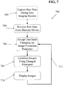
- the transmit controller 204 may direct one or more transmit elements of the probe 202 to transmit an ultrasound ping 502.
- the transmit controller 204 may also explicitly communicate 504 digital data about the transmitted ping (e.g., the identity of each transmit element being used for the ping, the magnitude of the ping, the duration of the ping, the frequency and specific waveform of the transmitted ultrasound signal, or other data) to the raw data memory 220.
- receive transducer elements of the probe 202 may begin receiving echoes and generating corresponding analog signals.
- a 'begin capture' signal may be sent to the AFE 212 and/or the ADC 214 after any such time interval has elapsed.
- Such a time interval may be selected so as to only capture echo data from a desired depth range within the imaged object.
- the AFE 212 may begin amplifying and/or filtering received analog echo signals that are then passed to the ADC 214.
- the ADC 214 may then sample 508 the analog signals at regular intervals (e.g., 25 MHz in some embodiments, but at higher or lower rates depending on factors such as the frequency of the transmitted pings, the capabilities and precision of the interpolator and beamformer, and the need to maintain at least Nyquist-defined lower minimum sample rates in order to avoid frequency aliasing).
- the ADC may generate a digital record containing a signal magnitude and a timestamp entry. This stream of digital records may then be recorded 510 in the raw data memory 202 for each sampled data point.
- each data point may also be passed 512 to the image formation block 230.
- the ADC 214 may be configured to store a fixed number of data points (e.g., as represented by variable 'Z' in FIG. 5 ). The process 500 of FIG. 5 may then be repeated 514 for any number of pings from any number of transmit apertures.
- digitized echo data may be sent directly from the ADC to the beamformer (in some cases after performing data conditioning steps, such as additional filtering, interpolation, down-sampling, up-sampling, etc.), and images may be beamformed, processed and displayed substantially in real-time with minimal latency.
- data conditioning steps such as additional filtering, interpolation, down-sampling, up-sampling, etc.
- images may be beamformed, processed and displayed substantially in real-time with minimal latency.
- any of various methods may be used to reduce the amount of processing needed to form images. For example, various data reduction methods may be used to minimize a human-perceptible latency between a user (e.g., a sonographer) changing the position of the probe and seeing the corresponding change displayed by the imaging system.
- a user may view an ultrasound image on a display screen 130 of a control panel 100 while moving the probe relative to the body being imaged. Once finding a desired view, the user may initiate a "capture" process on the ultrasound imaging control system. The system may then record some quantity of digitized raw echo data in a long term memory device.
- a capture process may be initiated by pressing an appropriately purposed button 110 such as that illustrated in FIG. 2 .
- a capture process may be initiated through another user-interactive control 120, such as a touch-sensitive device, a dial, a slider, a retinal scanner, a voice command, a keyboard, a mouse, trackpad, touchpad, or a combination of user-interactive controls.
- raw echo data capture may be initiated by remote control via a network connection.
- an ultrasound imaging system 200 may be configured to continuously store the most recent X seconds of raw echo data in either or both of a temporary memory device and/or a long-term memory device (also known as a "circular buffer").
- a temporary memory device and/or a long-term memory device also known as a "circular buffer”
- the length of time 'X' for which raw echo data is continuously stored may depend on the capacity of the temporary memory device and or the long-term memory device, as well as the memory space needed to capture each fraction of a second of raw echo data.
- the system may be configured to continuously replace old data with new data in order to maintain a continuous store of the most recent six seconds of data.
- the value of X may be a user-configurable or a predetermined time period less than or equal to the total capacity of the volatile and non-volatile memory.
- the "capture" process may be initiated retroactively or in advance.
- a user may instruct the system (e.g., through a user interface interaction) to save the previous X seconds of data.
- the user may instruct the system to save the next X seconds of data.
- a combination of retroactive and pre-active raw echo data may be captured and stored in a raw data memory device.
- raw echo data stored in the raw data memory device 220 may be retrieved and processed for real-time or near-real-time display of images.
- raw echo data may be retrieved from a raw data memory device 220 and processed for playback in slow motion or fast motion (e.g., time-lapse) in order to see details not visible in real time.
- elements of a probe may be divided into two receive apertures, and eight transmit apertures.
- a single time-domain frame may be formed from echoes of eight pings transmitted from each of the eight transmit apertures received with elements of each of the first and second receive apertures.
- a single time-domain frame may be composed of a total of 16 second level image layers, (eight second-level image layers from each receive aperture).
- the number of time-domain frames may be increased (e.g., in order to create "slow motion" video) by forming each time-domain frame from a combination of a smaller number of second level images (e.g., eight second level images instead of 16).
- the number of time-domain frames may be decreased (e.g., in order to create "time-lapse” video) by forming each time-domain frame from a combination of a greater number of second level images (e.g., 32 or 64 second level images instead of 16).
- a probe may be divided into three receive apertures, and 16 transmit apertures.
- a single time-domain frame may be formed from echoes of 16 pings transmitted from each of the 16 transmit apertures received with elements of each of the first, second and third receive apertures.
- a single time-domain frame may be composed of a total of 48 second level image layers, (16 second-level image layers from each receive aperture).
- the number of time-domain frames may be increased (e.g., in order to create "slow motion" video) by forming each time-domain frame from a combination of a smaller number of second level images (e.g., eight or 24 second level images instead of 48).
- the number of time-domain frames may be decreased (e.g., in order to create "time-lapse” video) by forming each time-domain frame from a combination of a greater number of second level images (e.g., 64 or 96 second level images instead of 48).
- a greater number of second level images e.g., 64 or 96 second level images instead of 48.
- some desired processing steps may require more processing time or computing power than may be available within time and hardware constraints of a live, real-time imaging session with an ultrasound imaging system.
- raw echo data stored in the raw data memory device 220 of an ultrasound system may be retrieved and processed for later display of images.
- echo data may be re-processed and displayed hours, days, weeks, months, or even years after a patient-present ultrasound data capture session.
- subsequent processing and display may occur on entirely different hardware, firmware and/or software from the system used to capture the ultrasound echo data - processing may even take place on cloud-based distributed systems, for example, with the resultant images streamed to mobile devices such as wireless tablets, smart phones, or other internet-connected display systems.
- mobile devices such as wireless tablets, smart phones, or other internet-connected display systems.
- raw echo data that is captured and stored in a raw data memory device as described above may subsequently be copied or forwarded to an external (e.g., a backup) memory storage device.
- Such data transmissions may take place over any available wired or wireless data transfer system, such as Bluetooth, IR/Infra-Red, USB, IEEE 1394 Firewire, Thunderbolt, Ethernet/Intranet/Internet (TCP/IP, FTP, etc.) or others.
- the data may be loaded back onto an ultrasound imaging system (e.g., the same system used for insonification and raw echo data capture or a similarly-configured ultrasound imaging system) for re-processing, re-beamforming and image viewing.
- an ultrasound imaging system e.g., the same system used for insonification and raw echo data capture or a similarly-configured ultrasound imaging system
- a personal computer may be configured with software and/or hardware to beamform and/or process the raw echo data without the use of a dedicated ultrasound imaging system.
- raw echo data may be beamformed, processed and displayed by software on any other suitably configured computational device or system, such as a tablet or smart phone.
- raw echo data may be uploaded over a network to a network-accessible server which may process image data remotely.
- FIG. 4 illustrates an embodiment of an ultrasound data capture & transmission device 260 that may be configured with minimal hardware components for communication of raw echo data to a remote imaging system 262 via a communications device 264 and a wired or wireless network 266.
- the ultrasound data capture device 260 of FIG. 4 may include a transmit controller 204, an AFE 212 and an ADC 214 as described above.
- the device 260 may instead include a communications device 264 configured to transmit raw echo data to a remote system 262 via a network 266.
- the remote system 262 may include hardware, firmware and software configured to beamform and process the raw echo data captured by the device 260.
- the communications device may be configured to stream raw echo data in real time to the remote system.
- the ultrasound data capture device 260 may include an internal memory device 220 for short term storage of raw echo data (e.g., as a transmission buffer).
- an internal memory device 220 may be configured for longer term storage of raw echo data within the capture device 260.
- the internal raw data memory device 220 may comprise a removable data storage device such as an SD card, an optical storage device (such as a CD or DVD) or any other solid state non-volatile digital memory device.
- a patient may visit a sonographer and the sonographer may conduct an ultrasound examination during which raw echo data is captured and stored.
- Hours, days or weeks later i.e., any time after the session, even long after patient is physically present
- a physician may use a personal computer or an imaging system to re-examine images produced during the examination session.
- such re-examination may include several processes that are only possible with access to raw echo data. Examples of such processes will now be described.
- raw data from an imaging session may be stored along with raw echo data captured while imaging a calibration phantom.
- Raw echo data of a phantom imaging session may be used for later calibration of the imaging session data by correcting transducer element position assumptions made during beamforming.
- Information describing the position of each transducer element may be obtained by a calibration process as described in Applicants' prior applications.
- Such element position data may be stored in a calibration memory device 220, which may be physically located with other electronics, or may be located in a remote network-accessible server.
- the element-position information may change between performing a calibration operation and capturing raw ultrasound data. For example, a probe may be dropped, damaged or may be otherwise altered before or during a raw echo data capture session.
- the ability to re-process stored raw echo data means that a probe may actually be re-calibrated after raw echo data is captured, and the data may be re-beamformed using the updated element position information.
- raw echo data stored in a raw data memory device may be analyzed to determine that a probe is actually out of calibration.
- Some embodiments of ultrasound imaging systems with a raw data memory may enable many unique user interactions that may dramatically extend the diagnostic usefulness of ultrasound imaging. By capturing and storing raw echo data during an imaging session, such ultrasound imaging systems may allow a user to adjust fundamental beamforming and image processing settings to obtain dramatically improved images and/or alternate views or details using only the stored raw echo data.
- stored raw echo data may be re-beamformed at any time after the raw echo data has been captured.
- beamforming in the context of multiple aperture ultrasound imaging using a ping transmission system is generally the process of determining a display location for each reflector based on trigonometric relationships between the reflector, the location of a transmit element, and the location of a receive element. Such trigonometric relationships are determined based on a distance calculation using an assumed speed-of-sound and the time interval between a transmitted ping and a received echo for a given reflector.
- the display location of any given reflector may be determined by several factors, each of which may be dependent on several other factors.
- variable factors that go into beamforming calculations or other image formation and/or image processing steps may be adjusted or optimized to further improve image quality.
- potentially variable quantities such as the speed of sound and the locations of transmit or receive elements may be optimized to improve image quality.
- the ability to re-beamform ultrasound data may also facilitate an improved ability to "zoom in” on a desired region of an image without losing any image resolution.
- This may be understood with an analogy to digital photography.
- Many digital cameras have an “optical zoom” function and a “digital zoom” function.
- the “optical zoom” optically gives the impression of bringing the subject closer to the camera, thereby increasing the size of the image.
- the "optically zoomed” image benefits from the full pixel resolution of the camera's image capture device.
- the "digital zoom” merely crops the image and increases the size of the captured pixels, thereby giving the impression of the same "zoom” result, but at the expense of reduced image resolution with each incremental "digital zoom” step.
- an ultrasound imaging system with a pre-beamformer memory device may provide the ability to zoom in without losing image resolution.
- the ability to zoom in and re-beamform ultrasound image data within a smaller area than an original image is analogous to an "optical zoom” because the beamformer may produce a full-resolution image from only the image data within a desired "zoomed-in" region of the image.
- Generating ultrasound images using a multiple aperture ping imaging process means that images from an entire region of interest are "in focus" at all times. This is true because each transmitted ping illuminates the entire region, and receive apertures receive echoes from the entire region. In such cases, the maximum extent of the image may be primarily limited by attenuation and signal-to-noise factors rather than by the confined focus of transmit or receive beamforming apparatuses. As a result, a full-resolution image may be formed from any portion of an insonified region of interest using the same set of raw echo data.
- image window will be used herein to refer to a portion of the entire insonified region of interest that is to be beamformed and displayed. Therefore, in various embodiments, an image window may be changed by zooming or panning from one image window to another. In some embodiments, simultaneous images may be formed of multiple overlapping or non-overlapping image windows within the insonified region.
- the only imaged region in focus is the region within the depth range at which the transmitted ultrasound signals are focused.
- such systems (even if they were to employ a pre-beamformer memory) are limited in their ability to construct images of portions of the insonified region other than those originally displayed during a real-time imaging session.
- the system typically interpolates data in between displayed pixels, because additional sample data is not available to fill in those gaps otherwise.
- the system may triangulate received echoes using an assumed speed-of-sound value, element position data, time delays of received echoes and a coherent/incoherent summation algorithm to form an image.
- the system may form a real-time image with a pixel resolution optimized for a particular display. In doing so, in the case of display devices with native resolutions lower than the actual beamformed resolution, some echo data representing points between the displayed image pixels may be ignored.
- hardware limitations such as limits imposed by processing or data transmission electronics, may necessitate using less than all available echo data when beamforming for real-time display. For these reasons or others, under some circumstances, a system may be limited to using only a portion of all available echo data for forming an image.
- a user may simply define a new view area anywhere within that region.
- the system may then beamform the echo data representing echoes within the selected region by triangulating the echoes using an assumed speed-of-sound value, element position data, time delays of received echoes and a coherent/incoherent summation algorithm to form new image pixels of only the selected region.
- the new image may be formed with the full beamforming resolution, even if the selected region was not visible in the original real-time image.
- the various beamforming parameters may also be changed relative to values used during a real-time imaging session.
- a somewhat lower level of skill may be acceptable for capturing raw data during a real-time imaging session.
- a first region of interest may be defined to include a first anatomical structure such as a cross-section of substantially an entire heart of a patient, while a second region of interest may be defined to include a zoomed-in region of the first region in order to increase the image size of a portion or sub-structure of the anatomical structure, such as an aortic valve of the heart.
- the moving images of the structure and the sub-structure e.g., the heart and the valve
- the moving images of the structure and the sub-structure will be perfectly synchronized and may be viewed simultaneously to visualize the action of different regions of the heart (or other structure) at the same point in the cardiac cycle (or other movement of the anatomical structure).
- a third image may also be produced to show simultaneous action of another portion of the insonified region, highlighting another sub-structure or an entirely separate structure, such as the tricuspid valve of the heart or an adjacent organ.
- the same techniques may be used to view regions of other organs (e.g., lungs, liver, kidneys, or muscular-skeletal structures such as wrist joints, ankle joints, knee joints, shoulder joints, hip joints or a spine).
- first and second image windows covering non-coplanar segments of a common three-dimensional volume may be extracted from a stored echo dataset, and those image windows may be independently beamformed and displayed simultaneously in synchronicity.
- the above methods of zooming into regions of an image may allow for very accurate measurements of anatomical or structural features within an insonified region. Measurements are made possible by the fact that, at any chosen "zoom" level, the relationship between pixel size and imaged object size is known exactly as a result of the pixel-oriented beamforming method described above. For example, regardless of what zoom level was displayed during real-time imaging, if a feature is within the insonified region and included in an echo data set, a user may later zoom in to view and accurately measure features such as artery diameter, vein diameter, heart chamber size, fetal heart size or any other desired feature or object.
- image layers formed from different pings or from different receive apertures may be combined using various combinations of coherent and incoherent summation in order to accommodate speed-of-sound differences across a large total aperture, or to improve the image resolution or speckle reduction in the combined image.
- further coherent and incoherent summation algorithms may be applied to stored raw echo data in order to seek a different result.
- transmit and receive apertures may be re-defined after ultrasound data has been captured.
- the size, location and number of transmit or receive apertures may be changed depending on a particular target object geometry or other factors. In some embodiments, such changes in the size, location or number of apertures of may be made adaptively in order to optimize the quality of an image produced from stored raw echo data.
- Applicants' prior application ( US Patent Application No. 13/730,346, filed December 28, 2012 , titled "M-Mode Ultrasound Imaging of Arbitrary Paths") describes systems and methods for defining and displaying an arbitrary M-mode path.
- new M-mode paths may be defined and displayed based on stored raw echo data that has been re-beamformed during a raw data viewing session.
- an m-mode path may be defined in one field of view, and may be displayed along with a completely different field of view that does not necessarily contain the same feature as the M-mode path.
- raw echo data corresponding to points along the m-mode path may be retrieved from a raw data memory device and beamformed independent of raw echo data used to form a complete image.
- Doppler imaging and Elastographic imaging involve transmit patterns that are not necessarily present during all multiple aperture ping imaging sessions.
- ping-based Doppler ultrasound imaging involves transmitting relatively low frequency pings (compared to an imaging frequency) from one or two transmit apertures at a very high ping repetition rate (e.g., nearly or faster than a rate corresponding to a round trip ping travel time).
- Ping-based elastographic imaging may also involve transmitting imaging pings at a very high ping repetition rate following transmission of a shear-wave inducing pulse.
- resulting raw echo data may be captured and stored, whether or not the echoes are processed to display Doppler or Elastography results during the initial imaging session.
- Doppler or Elastography results may be interpreted or analyzed using the captured raw echo data retrieved from a raw data memory device.
- multiple aperture Doppler patterns may be transmitted during an imaging session, and the resulting Doppler echo data may be captured and stored without processing or displaying color flow Doppler during the live imaging session.
- the stored raw echo data may be later retrieved from memory and processed using the same or different processing hardware in order to visualize and analyze the results of the Doppler imaging.
- multiple aperture Elastography patterns may be transmitted during an imaging session, and the resulting echo data may be captured and stored without processing or displaying strain information during the live imaging session.
- the stored raw echo data may be later retrieved from memory and processed using the same or different processing hardware in order to visualize and analyze the results of the Elastography process.
- image data may be compressed in order to produce real-time images without significant perceptible delay.
- compression may have the effect of combining images obtained at different points in time (e.g., by combining image layers obtained from multiple transmitted pings). This may have the effect of reducing an actual displayed frame rate from a maximum possible frame rate at which echo data is captured.
- a much higher frame rate i.e., a higher number of frames per second
- images formed at the much higher frame rate may be viewed frame-by-frame or in slow motion While slow motion playback may occur at a lower number of frames per second relative to a display frame rate, because such frames may represent events that occurred at shorter time intervals compared with images presented for real-time viewing, more detail may be seen. For example, some movements of portions of a heart valve occur much faster than can be captured with traditional ultrasound systems. The ability to view images of such motion at a much higher frame-capture rate may enable dramatic improvements to diagnostic capabilities.
- any other downstream image or video processing steps may be re-applied, modified or improved after re-processing raw echo data.
- various video processing filters e.g., mean, median, squaring, Gaussian, despeckle, high-pass, edge enhancement, contrast enhancement, unsharp masking or other image and video processing filters
- Raw data of three-dimensional volumes may also be beneficially captured, stored, and re-beamformed using similar systems and methods.
- the same ping-based imaging techniques described above may be applied to 3D volumetric data by transmitting ping signals that are not constrained to a single plane (e.g., three-dimensional semi-spherical or near-semi-spherical ultrasound signals), and receiving echoes with receive elements displaced from one another along at least two orthogonal axes perpendicular to the imaged medium.
- Multiple aperture ultrasound probes configured for ping-based 3D volumetric imaging may have large total apertures, which may be substantially greater than any expected coherence width for an intended imaging application.
- 3D volumetric data may be captured and stored using substantially the same systems and methods described above.
- a multiple aperture probe for 3D imaging may have substantially more transducer elements than a probe intended primarily for 2D imaging.
- an imaging system for capturing and storing 3D volumetric data during a ping-based imaging process may include substantially more receive channels and may also include a larger capacity raw data memory device.
- the raw echo data stored in the memory device may be structured as described above, such that echoes may be distinguished based on the particular receive element that received them and the particular transmitted ping that generated the echoes.
- Beamforming 3D ping-based echo data may also be performed using similar systems and methods to those used for beamforming 2D ping-based echo data.
- Each digitized sample value may represent a scatterer from the insonified region of interest.
- the amplitude of each received sample along with its time of arrival and the exact positions of the transmitting and receiving transducers may be analyzed to define a locus of points identifying potential positions of the scatterer.
- a locus is a three-dimensional ellipsoid having as its foci the positions of the transmit and receive transducers.
- Each unique combination of transmit and receive transducer elements may define a separate view of the same reflector. Thus, by combining information from multiple transmit-receive transducer combinations, the actual location of each reflector may be more accurately represented.
- an image in a 3D array of voxels may be assembled in computer memory by beginning with an evaluation of a selected digital sample.
- the selected digitized sample value may be written into every voxel indicated by the corresponding ellipsoid described above. Proceeding to do the same with every other collected sample value, and then combining all resulting ellipsoids may produce a more refined image.
- Real scatterers are indicated by the intersection of many ellipsoids whereas parts of the ellipsoids not reinforced by other ellipsoids will have low levels of signal and may be treated as noise (i.e., eliminated or reduced by filters or other image processing steps).
- the order of computation may be changed by beginning with a selected voxel in a final 3D image volume to be produced. For example, for a selected voxel, the closest stored sample may be identified for each transmitter/receiver pair. All samples corresponding to the selected voxel (i.e., all samples with an ellipsoid that intersects the voxel) may then be evaluated and summed (or averaged) to produce a final representation of the voxel.
- Closeness of a sample to a selected voxel may be determined by calculating the vector distance from the three-dimensional position of a transmitter (i.e., the transmitter from which the ping signal was transmitted to produce the echo sample) to the selected voxel position plus the vector distance from the selected voxel position to the position of a receiver at which the sample was received.
- a linear distance may be related to the time-divided sample values by dividing the total path length by speed of sound through the imaged object.
- the samples corresponding to a calculated time may be associated with the selected voxel.
- ping signals insonify an entire region to be imaged
- echo data obtained via ping-based imaging is seamless.
- 2D images assembled from a series of scanlines typically require some amount of interpolation of image data in spaces in between adjacent scanlines.
- volumetric data assembled from a series of planar slices also tend to require some amount of interpolation of image data in spaces in between adjacent planar slices.
- the seamless nature of ping-based echo data means that arbitrary 2D slices may be taken through any portion of a 3D volume without the need for interpolation.
- non-planar or curved slice may be taken through a section of volumetric data, and the result of the curved-path slice may be displayed on a two-dimensional display, either as a flattened planar image or as a perspective drawing.
- Such information may also be presented via a three-dimensional display such as a holographic display or a stereoscopic display.
- raw echo data from a volumetric imaging session may be retrieved from a memory device, some or all of the volume may be beamformed and displayed as an image, a desired region of the volume may be selected (automatically by software or manually by an operator), and the selected region may be re-beamformed and presented as a new image.
- FIG. 6 illustrates a process 600 by which a practitioner may use a suitably configured imaging system to examine raw echo data captured during a live imaging session 500 that may have been performed by the same practitioner or a different practitioner at a previous time and/or in a different location.
- Raw data from the imaging session may be retrieved from a memory device 601
- the practitioner may direct the system to construct images 602 from the raw data using a predetermined set of image formation parameters, and the practitioner may then view the resulting images 604.
- the practitioner may then change one or more image formation parameters 606 in an attempt to improve the image or to change a portion of the insonified region to view (e.g., changing an image window by zooming in, zooming out, or panning).
- the practitioner may then direct the system to construct and display images using the changed parameters 608, and may then view the new images 610.
- the steps of changing image formation parameters 606, constructing images using the changed parameter(s) 708 and displaying new images 610 may be repeated 612 as many times as desired.
- FIG. 7 illustrates a process 700 that may be performed by a suitably configured ultrasound imaging system in order to re-process raw ultrasound echo data captured during a live imaging session 500.
- the process 700 may include retrieving the raw data from a memory device 704, accepting user input indicating one or more image formation parameters to be changed 706, constructing images using the changed image formation parameter(s) 708, and displaying the new image(s) 710.
- the steps of accepting user input 706, constructing images using the changed parameter(s) 708 and displaying new images 710 may be repeated 712 as many times as desired.
- the user input may explicitly specify the image formation parameters to be changed, or the user input may implicitly indicate image formation parameters to be changed.
- An example of an explicit parameter to change may include changing a speed of sound value, while an example of an implicitly specified parameter may include a selection of an image layer combination algorithm that combines image layers using a combination of coherent and incoherent addition.
- the changed image formation parameters may include beamforming parameters, such as a speed of sound value, one or more transducer element position variables, or a weighting factor.
- Image formation parameters may also include a grouping of transducer elements into apertures, or image layer combining parameters such as changing a number of image layers per frame or an algorithm for combining image layers at different levels using coherent or incoherent addition.
- Changing image parameters may also include selecting an M-mode line to display, or selecting a two-dimensional slice from a three-dimensional volume.
Landscapes
- Engineering & Computer Science (AREA)
- Physics & Mathematics (AREA)
- Health & Medical Sciences (AREA)
- Life Sciences & Earth Sciences (AREA)
- Remote Sensing (AREA)
- Radar, Positioning & Navigation (AREA)
- Acoustics & Sound (AREA)
- General Physics & Mathematics (AREA)
- Computer Networks & Wireless Communication (AREA)
- Surgery (AREA)
- Molecular Biology (AREA)
- Veterinary Medicine (AREA)
- Public Health (AREA)
- Biophysics (AREA)
- Nuclear Medicine, Radiotherapy & Molecular Imaging (AREA)
- Pathology (AREA)
- Radiology & Medical Imaging (AREA)
- Biomedical Technology (AREA)
- Heart & Thoracic Surgery (AREA)
- Medical Informatics (AREA)
- General Health & Medical Sciences (AREA)
- Animal Behavior & Ethology (AREA)
- Multimedia (AREA)
- Computer Vision & Pattern Recognition (AREA)
- Gynecology & Obstetrics (AREA)
- Theoretical Computer Science (AREA)
- Human Computer Interaction (AREA)
- General Engineering & Computer Science (AREA)
- Signal Processing (AREA)
- Ultra Sonic Daignosis Equipment (AREA)
Claims (5)
- Verfahren für eine Ultraschallbildgebung, das folgende Schritte umfasst:Übertragen eines Ultraschallimpulses (502), um eine Region von Interesse zu beschallen;Generieren, in Echtzeit, eines ersten Bildes eines ersten Abschnitts einer Region von Interesse;Speichern von Echodaten, die von der beschallten Region empfangen werden, in einer Speichervorrichtung (220);nach dem Speicherschritt, Abrufen der Echodaten von der Speichervorrichtung;Verarbeiten der Echodaten, um ein zweites Bild eines zweiten Abschnitts der Region von Interesse zu erzeugen, wobei sich der erste und der zweite Abschnitt der Region von Interesse gänzlich nicht überlappen;Verarbeiten der Echodaten, um ein drittes Bild eines dritten Abschnitts der Region von Interesse zu erzeugen, wobei das dritte Bild einen Anteil der Region von Interesse abdeckt, der in dem zweiten Bild nicht vorhanden ist; undgleichzeitiges Anzeigen des zweiten Bildes und des dritten Bildes,dadurch gekennzeichnet, dass ein Übertragen eines Ultraschallimpulses (502), um eine Region von Interesse zu beschallen, das Übertragen eines unfokussierten Ping-Ultraschallimpulses (502) mit einem Bildgebungssystem mit mehreren Aperturen (202) umfasst, und dass das Erzeugen eines zweiten Bildes und das Erzeugen eines dritten Bildes ferner ein Kombinieren mehrerer Bildschichten umfasst, wobei jede Bildschicht einer unterschiedlichen Kombination eines übertragenen Ultraschallimpulses und einer Empfangsapertur entspricht, und wobei das Erzeugen des zweiten Bildes das Kombinieren einer unterschiedlichen Anzahl von Bildschichten als das Erzeugen des dritten Bildes umfasst.
- Verfahren nach Anspruch 1, wobei der Generierungsschritt ein Verwenden eines ersten Satzes von Strahlbildungsparametern umfasst und der Verarbeitungsschritt ein Verwenden eines zweiten Satzes von Strahlbildungsparametern umfasst, der sich von dem ersten Satz von Strahlbildungsparametern unterscheidet.
- Verfahren nach Anspruch 1, wobei das zweite Bild eine höhere Pixelauflösung als das erste Bild aufweist.
- Verfahren nach Anspruch 1, wobei ein Querschnitt eines menschlichen Herzens in dem ersten Bild sichtbar ist und lediglich ein erster Anteil des Herzens in dem dritten Bild sichtbar ist.
- Verfahren nach Anspruch 1, das ferner ein Messen eines Objekts umfasst, das in dem zweiten Bild sichtbar ist.
Priority Applications (1)
| Application Number | Priority Date | Filing Date | Title |
|---|---|---|---|
| EP21175513.7A EP3893022B1 (de) | 2012-09-06 | 2013-08-20 | Speicherarchitektur für ein ultraschallbildgebungssystem |
Applications Claiming Priority (2)
| Application Number | Priority Date | Filing Date | Title |
|---|---|---|---|
| US201261691717P | 2012-09-06 | 2012-09-06 | |
| PCT/US2013/055790 WO2014031642A1 (en) | 2012-08-21 | 2013-08-20 | Ultrasound imaging system memory architecture |
Related Child Applications (1)
| Application Number | Title | Priority Date | Filing Date |
|---|---|---|---|
| EP21175513.7A Division EP3893022B1 (de) | 2012-09-06 | 2013-08-20 | Speicherarchitektur für ein ultraschallbildgebungssystem |
Publications (3)
| Publication Number | Publication Date |
|---|---|
| EP2887879A1 EP2887879A1 (de) | 2015-07-01 |
| EP2887879A4 EP2887879A4 (de) | 2016-05-11 |
| EP2887879B1 true EP2887879B1 (de) | 2021-05-26 |
Family
ID=50148640
Family Applications (2)
| Application Number | Title | Priority Date | Filing Date |
|---|---|---|---|
| EP21175513.7A Active EP3893022B1 (de) | 2012-09-06 | 2013-08-20 | Speicherarchitektur für ein ultraschallbildgebungssystem |
| EP13830423.3A Active EP2887879B1 (de) | 2012-09-06 | 2013-08-20 | Ultraschallabbildungsverfahren |
Family Applications Before (1)
| Application Number | Title | Priority Date | Filing Date |
|---|---|---|---|
| EP21175513.7A Active EP3893022B1 (de) | 2012-09-06 | 2013-08-20 | Speicherarchitektur für ein ultraschallbildgebungssystem |
Country Status (8)
| Country | Link |
|---|---|
| US (3) | US9986969B2 (de) |
| EP (2) | EP3893022B1 (de) |
| JP (2) | JP6306012B2 (de) |
| KR (1) | KR102176319B1 (de) |
| CN (1) | CN104582582B (de) |
| HK (1) | HK1208330A1 (de) |
| IN (1) | IN2015DN00764A (de) |
| WO (1) | WO2014031642A1 (de) |
Families Citing this family (65)
| Publication number | Priority date | Publication date | Assignee | Title |
|---|---|---|---|---|
| US8234923B2 (en) * | 2004-09-20 | 2012-08-07 | Innervision Medical Technologies Inc. | Systems and methods for ultrasound imaging |
| US20100262013A1 (en) * | 2009-04-14 | 2010-10-14 | Smith David M | Universal Multiple Aperture Medical Ultrasound Probe |
| EP2088932B1 (de) | 2006-10-25 | 2020-04-08 | Maui Imaging, Inc. | Verfahren und vorrichtung zur herstellung von ultraschallbildern mithilfe mehrerer öffnungen |
| US9282945B2 (en) | 2009-04-14 | 2016-03-15 | Maui Imaging, Inc. | Calibration of ultrasound probes |
| WO2011103303A2 (en) | 2010-02-18 | 2011-08-25 | Maui Imaging, Inc. | Point source transmission and speed-of-sound correction using mult-aperture ultrasound imaging |
| EP2627257B1 (de) | 2010-10-13 | 2019-04-17 | Maui Imaging, Inc. | Konkave ultraschallwandler und 3d-arrays |
| WO2013101988A1 (en) | 2011-12-29 | 2013-07-04 | Maui Imaging, Inc. | M-mode ultrasound imaging of arbitrary paths |
| KR101562204B1 (ko) * | 2012-01-17 | 2015-10-21 | 삼성전자주식회사 | 프로브 장치, 서버, 초음파 영상 진단 시스템, 및 초음파 영상 처리 방법 |
| EP2816958B1 (de) | 2012-02-21 | 2020-03-25 | Maui Imaging, Inc. | Bestimmung der materialsteifigkeit mittels ultraschall mit mehreren aperturen |
| CN104203110B (zh) | 2012-03-26 | 2017-06-06 | 毛伊图像公司 | 用于通过应用加权因子来提高超声图像品质的系统和方法 |
| JP5946324B2 (ja) * | 2012-05-25 | 2016-07-06 | 富士フイルム株式会社 | 超音波診断装置およびデータ処理方法 |
| KR102176193B1 (ko) | 2012-08-10 | 2020-11-09 | 마우이 이미징, 인코포레이티드 | 다중 어퍼처 초음파 프로브들의 교정 |
| CN103676827A (zh) | 2012-09-06 | 2014-03-26 | Ip音乐集团有限公司 | 用于远程控制音频设备的系统和方法 |
| US9510806B2 (en) | 2013-03-13 | 2016-12-06 | Maui Imaging, Inc. | Alignment of ultrasound transducer arrays and multiple aperture probe assembly |
| US9883848B2 (en) | 2013-09-13 | 2018-02-06 | Maui Imaging, Inc. | Ultrasound imaging using apparent point-source transmit transducer |
| US9476859B2 (en) * | 2013-12-16 | 2016-10-25 | Olympus Ndt, Inc. | Automatic calibration for phased array inspection of girth weld |
| KR20150118734A (ko) * | 2014-04-15 | 2015-10-23 | 삼성전자주식회사 | 초음파 영상 장치 및 그 제어방법 |
| WO2016028787A1 (en) * | 2014-08-18 | 2016-02-25 | Maui Imaging, Inc. | Network-based ultrasound imaging system |
| US11064891B2 (en) * | 2014-09-05 | 2021-07-20 | Canon Kabushiki Kaisha | Object information acquiring apparatus |
| EP3000401B1 (de) | 2014-09-23 | 2022-11-09 | Samsung Medison Co., Ltd. | Verfahren und vorrichtung zur erzeugung eines ultraschallbildes |
| KR102270721B1 (ko) * | 2014-09-23 | 2021-06-30 | 삼성메디슨 주식회사 | 초음파 영상 장치 및 초음파 영상 생성 방법 |
| KR102297346B1 (ko) * | 2014-10-31 | 2021-09-03 | 삼성메디슨 주식회사 | 의료 영상 장치 및 그에 따른 의료 영상을 디스플레이 하는 방법 |
| EP3240484B1 (de) * | 2015-01-02 | 2019-03-27 | Esaote S.p.A. | Verfahren zur quantifizierung der elastizität eines materials durch ultraschall |
| JP6770973B2 (ja) * | 2015-03-30 | 2020-10-21 | マウイ イマギング,インコーポレーテッド | 物体の動きを検出するための超音波イメージングシステム及び方法 |
| US10675006B2 (en) * | 2015-05-15 | 2020-06-09 | Siemens Medical Solutions Usa, Inc. | Registration for multi-modality medical imaging fusion with narrow field of view |
| US9823224B2 (en) | 2015-11-09 | 2017-11-21 | Caterpillar Inc. | Weld inspection method and system |
| JP6672809B2 (ja) * | 2016-01-13 | 2020-03-25 | コニカミノルタ株式会社 | 超音波診断装置、及び超音波信号処理方法 |
| JP6942847B2 (ja) * | 2016-01-21 | 2021-09-29 | キヤノン株式会社 | 被検体情報取得装置および信号処理方法 |
| CN108778530B (zh) | 2016-01-27 | 2021-07-27 | 毛伊图像公司 | 具有稀疏阵列探测器的超声成像 |
| US20170307755A1 (en) | 2016-04-20 | 2017-10-26 | YoR Labs | Method and System for Determining Signal Direction |
| US10401492B2 (en) * | 2016-05-31 | 2019-09-03 | yoR Labs, Inc. | Methods and systems for phased array returning wave front segmentation |
| US10650621B1 (en) | 2016-09-13 | 2020-05-12 | Iocurrents, Inc. | Interfacing with a vehicular controller area network |
| JP6829801B2 (ja) * | 2016-11-02 | 2021-02-17 | 株式会社プロアシスト | 超音波アレイセンサシステム |
| KR20180072358A (ko) * | 2016-12-21 | 2018-06-29 | 삼성메디슨 주식회사 | 초음파 진단 장치 및 초음파 진단 장치 제어 방법 |
| US20190005640A1 (en) * | 2017-07-03 | 2019-01-03 | General Electric Company | Physiology maps from multi-parametric radiology data |
| EP3651653A1 (de) * | 2017-07-10 | 2020-05-20 | SuperSonic Imagine | Operativ adaptives ultraschallbildgebungssystem |
| US11504097B2 (en) * | 2017-09-01 | 2022-11-22 | Clarius Mobile Health Corp. | Systems and methods for acquiring raw ultrasound data from an ultrasound machine using a wirelessly connected device |
| DE102017126158A1 (de) * | 2017-11-08 | 2019-05-09 | Fraunhofer-Gesellschaft zur Förderung der angewandten Forschung e.V. | Ultraschall-Bilderzeugungssystem |
| US10739316B2 (en) | 2017-12-11 | 2020-08-11 | Insightec, Ltd. | Phased array calibration for geometry and aberration correction |
| EP3740132A1 (de) * | 2018-01-19 | 2020-11-25 | Koninklijke Philips N.V. | Automatische pfadkorrektur während einer gezielten multimodalen fusionsbiopsie |
| CN111771138B (zh) * | 2018-02-27 | 2024-10-18 | 皇家飞利浦有限公司 | 具有用于根据欠采样超声数据产生图像的神经网络的超声系统 |
| DE102018204357A1 (de) * | 2018-03-21 | 2019-09-26 | H-Next Gmbh | Ultraschallvorrichtung zur medizinischen Untersuchung mittels Ultraschallwellen |
| CA3095049A1 (en) * | 2018-04-09 | 2019-10-17 | Butterfly Network, Inc. | Methods and apparatus for configuring an ultrasound system with imaging parameter values |
| US11435460B2 (en) * | 2018-05-07 | 2022-09-06 | Fujifilm Sonosite, Inc. | Ultrasound imaging system with style transfer image enhancement |
| US12138113B2 (en) * | 2018-11-30 | 2024-11-12 | Koninklijke Philips N.V. | Apparatus and method for detecting bone fracture |
| EP3983849A4 (de) * | 2019-06-14 | 2023-07-05 | BFLY Operations, Inc. | Verfahren und vorrichtungen zur erfassung von ultraschalldaten in verschiedenen höhensteuerwinkeln |
| DE102019124811B4 (de) | 2019-09-16 | 2021-05-12 | H-Next Gmbh | Ultraschallsystem und bildgebendes Ultraschallverfahren |
| US11547386B1 (en) | 2020-04-02 | 2023-01-10 | yoR Labs, Inc. | Method and apparatus for multi-zone, multi-frequency ultrasound image reconstruction with sub-zone blending |
| US11998391B1 (en) | 2020-04-02 | 2024-06-04 | yoR Labs, Inc. | Method and apparatus for composition of ultrasound images with integration of “thick-slice” 3-dimensional ultrasound imaging zone(s) and 2-dimensional ultrasound zone(s) utilizing a multi-zone, multi-frequency ultrasound image reconstruction scheme with sub-zone blending |
| CN111544038B (zh) * | 2020-05-12 | 2024-02-02 | 上海深至信息科技有限公司 | 一种云平台超声成像系统 |
| US11344281B2 (en) | 2020-08-25 | 2022-05-31 | yoR Labs, Inc. | Ultrasound visual protocols |
| US12138123B2 (en) | 2020-08-25 | 2024-11-12 | yoR Labs, Inc. | Unified interface for visualizing 2D, 3D and 4D ultrasound images |
| US11832991B2 (en) | 2020-08-25 | 2023-12-05 | yoR Labs, Inc. | Automatic ultrasound feature detection |
| US11452507B2 (en) * | 2020-08-31 | 2022-09-27 | GE Precision Healthcare LLC | Method and system for monitoring ultrasound probe health |
| US11998393B2 (en) * | 2020-10-20 | 2024-06-04 | GE Precision Healthcare LLC | System and method of signal processing for ultrasound arrays with mechanically adjustable transducer shapes |
| EP4236811A4 (de) * | 2020-11-02 | 2024-10-09 | Maui Imaging, Inc. | Systeme und verfahren zur verbesserung der ultraschallbildqualität |
| US11751850B2 (en) | 2020-11-19 | 2023-09-12 | yoR Labs, Inc. | Ultrasound unified contrast and time gain compensation control |
| US11704142B2 (en) | 2020-11-19 | 2023-07-18 | yoR Labs, Inc. | Computer application with built in training capability |
| US12153132B2 (en) * | 2020-11-24 | 2024-11-26 | Evident Canada, Inc. | Techniques to reconstruct data from acoustically constructed images using machine learning |
| IT202100004376A1 (it) * | 2021-02-25 | 2022-08-25 | Esaote Spa | Metodo di determinazione di piani di scansione nell’acquisizione di immagini ecografiche e sistema ecografico per l’attuazione del detto metodo |
| CN113056034B (zh) * | 2021-03-11 | 2023-02-24 | 深圳华声医疗技术股份有限公司 | 基于云计算的超声图像处理方法和超声系统 |
| CN117295975A (zh) * | 2021-05-10 | 2023-12-26 | 皇家飞利浦有限公司 | 相干复合超声图像生成以及相关联的系统、方法和设备 |
| IT202100012350A1 (it) | 2021-05-13 | 2022-11-13 | Esaote Spa | Sistema smaterializzato, multiutente per l’acquisizione, la generazione e l’elaborazione di immagini ecografiche |
| IT202100012335A1 (it) | 2021-05-13 | 2022-11-13 | Esaote Spa | Sistema multiutente per l’acquisizione, la generazione e l’elaborazione di immagini ecografiche |
| US12156761B1 (en) | 2024-03-05 | 2024-12-03 | yoR Labs, Inc. | Bayesian anatomically-driven, artificial-intelligence based intracardiac echocardiography object detection and prediction |
Family Cites Families (561)
| Publication number | Priority date | Publication date | Assignee | Title |
|---|---|---|---|---|
| US3174286A (en) | 1963-06-27 | 1965-03-23 | Gen Motors Corp | Master cylinder |
| JPS4911189A (de) | 1972-05-29 | 1974-01-31 | ||
| US3895381A (en) | 1973-02-21 | 1975-07-15 | Winston E Kock | Synthetic aperture imaging systems |
| AT343265B (de) | 1973-08-16 | 1978-05-26 | Siemens Ag | Gerat fur die messung der geschwindigkeit von insbesondere in leitungen stromenden medien |
| US4072922A (en) | 1975-11-13 | 1978-02-07 | Seiscom Delta Inc. | Method for seismic exploration for enhanced results in simulated cylindrical or plane waves |
| US4105018A (en) | 1976-02-02 | 1978-08-08 | University Of Utah | Acoustic examination, material characterization and imaging of the internal structure of a body by measurement of the time-of-flight of acoustic energy therethrough |
| US4097835A (en) | 1976-09-20 | 1978-06-27 | Sri International | Dual transducer arrangement for ultrasonic imaging system |
| US4055988A (en) | 1976-12-09 | 1977-11-01 | J. B. Engineering And Sales Company, Inc. | Alignment control apparatus for a turntable used in an ultrasonic testing system |
| JPS5444375A (en) | 1977-09-14 | 1979-04-07 | Oki Electric Ind Co Ltd | Ultrasonic wave reflection system |
| US4333474A (en) | 1978-02-06 | 1982-06-08 | New York Institute Of Technology | Ultrasonic imaging system |
| US4271842A (en) | 1978-03-03 | 1981-06-09 | Smith Kline Instruments, Inc. | Apparatus and method for providing multiple ultrasonic sector image displays |
| US4180792A (en) | 1978-03-09 | 1979-12-25 | General Electric Company | Transmit-receive transducer array and ultrasonic imaging system |
| JPS55103839A (en) | 1979-02-03 | 1980-08-08 | Fujitsu Ltd | Ultrasonic diagnosis apparatus |
| CA1137210A (en) | 1979-04-26 | 1982-12-07 | Francis S. Foster | Ultrasonic imaging method and device using one transducer having a line focus aligned with another transducer |
| US4259733A (en) | 1979-05-14 | 1981-03-31 | Seiscom Delta, Inc. | Multi-dimensional seismic imaging |
| US4265126A (en) | 1979-06-15 | 1981-05-05 | General Electric Company | Measurement of true blood velocity by an ultrasound system |
| US4327738A (en) | 1979-10-19 | 1982-05-04 | Green Philip S | Endoscopic method & apparatus including ultrasonic B-scan imaging |
| JPS56103327A (en) | 1980-01-21 | 1981-08-18 | Hitachi Ltd | Ultrasonic image pickup apparatus |
| US4325257A (en) | 1980-02-20 | 1982-04-20 | Kino Gordon S | Real-time digital, synthetic-focus, acoustic imaging system |
| JPS5731848A (en) | 1980-08-01 | 1982-02-20 | Fujitsu Ltd | Ultrasonic diagnostic device |
| JPS5849137A (ja) | 1981-09-18 | 1983-03-23 | 株式会社東芝 | 超音波血流測定装置 |
| US6324453B1 (en) | 1998-12-31 | 2001-11-27 | Automotive Technologies International, Inc. | Methods for determining the identification and position of and monitoring objects in a vehicle |
| JPS58223059A (ja) | 1982-06-21 | 1983-12-24 | Toshiba Corp | 超音波探傷装置 |
| US4452084A (en) | 1982-10-25 | 1984-06-05 | Sri International | Inherent delay line ultrasonic transducer and systems |
| JPS59101143A (ja) | 1982-12-02 | 1984-06-11 | 富士通株式会社 | 超音波による測定または加作用装置 |
| JPH064074B2 (ja) | 1983-02-14 | 1994-01-19 | 株式会社日立製作所 | 超音波診断装置およびこれを用いる音速計測方法 |
| JPS59174151A (ja) | 1983-03-25 | 1984-10-02 | 横河メディカルシステム株式会社 | 超音波映像装置 |
| US5141738A (en) | 1983-04-15 | 1992-08-25 | Schering Aktiengesellschaft | Ultrasonic contrast medium comprising gas bubbles and solid lipophilic surfactant-containing microparticles and use thereof |
| JPS6013109U (ja) | 1983-07-07 | 1985-01-29 | アロカ株式会社 | 超音波診断装置 |
| US4604697A (en) | 1983-08-05 | 1986-08-05 | Interspec, Inc. | Body imaging using vectorial addition of acoustic reflection to achieve effect of scanning beam continuously focused in range |
| JPS6068836A (ja) | 1983-09-24 | 1985-04-19 | 株式会社島津製作所 | 超音波診断装置 |
| US4539847A (en) | 1984-01-03 | 1985-09-10 | Texaco Inc. | Acoustic method and apparatus for measuring thickness of a coating layer on a substrate |
| JPS60150735A (ja) | 1984-01-18 | 1985-08-08 | 株式会社東芝 | 超音波診断装置 |
| US4662222A (en) | 1984-12-21 | 1987-05-05 | Johnson Steven A | Apparatus and method for acoustic imaging using inverse scattering techniques |
| US4781199A (en) | 1985-01-07 | 1988-11-01 | Kabushiki Kaisha Toshiba | System and method for measuring sound velocity of internal tissue in an object being investigated |
| JPS61203949A (ja) | 1985-03-04 | 1986-09-09 | 株式会社東芝 | 超音波診断装置 |
| US4669482A (en) | 1985-10-28 | 1987-06-02 | Board Of Regents, The University Of Texas System | Pulse echo method and apparatus for sound velocity estimation in vivo |
| US4817434A (en) | 1985-11-19 | 1989-04-04 | Forrest Anderson | Device for imaging three dimensions using simultaneous multiple beam formation |
| US4831601A (en) | 1986-10-31 | 1989-05-16 | Siemens Aktiengesellschaft | Apparatus for transmitting and receiving ultrasonic signals |
| FR2607631B1 (fr) | 1986-11-28 | 1989-02-17 | Thomson Cgr | Sonde pour appareil a ultrasons munie d'un arrangement concave d'elements piezo-electriques |
| US4893628A (en) | 1988-04-04 | 1990-01-16 | Bjorn Angelsen | Dual element ultrasonic transducer probe for combined imaging of tissue structures and blood flow in real time |
| US4893284A (en) | 1988-05-27 | 1990-01-09 | General Electric Company | Calibration of phased array ultrasound probe |
| US5197475A (en) | 1988-08-10 | 1993-03-30 | The Board Of Regents, The University Of Texas System | Method and apparatus for analyzing material properties using ultrasound |
| JP2777197B2 (ja) | 1989-06-13 | 1998-07-16 | 株式会社東芝 | 超音波診断装置 |
| JPH03126443A (ja) | 1989-10-11 | 1991-05-29 | Matsushita Electric Ind Co Ltd | 超音波探触子 |
| US5050588A (en) | 1990-02-08 | 1991-09-24 | Richard Grey | High energy ultrasonic lens assembly with mounting facets |
| JP2849159B2 (ja) | 1990-05-11 | 1999-01-20 | 淑 中山 | 超音波診断装置 |
| JPH0467856A (ja) | 1990-07-09 | 1992-03-03 | Yokogawa Medical Syst Ltd | バイスタティック送受信による超音波イメージャー |
| JP3015527B2 (ja) | 1991-08-14 | 2000-03-06 | 株式会社東芝 | 超音波診断装置 |
| US5161536A (en) | 1991-03-22 | 1992-11-10 | Catheter Technology | Ultrasonic position indicating apparatus and methods |
| US5191890A (en) | 1991-04-22 | 1993-03-09 | Interspec, Inc. | Ultrasonic probe assembly |
| US5230339A (en) | 1991-06-13 | 1993-07-27 | Array Tech, Inc. | Performance evaluation of ultrasonic examination equipment |
| US5442462A (en) | 1992-06-10 | 1995-08-15 | D.V.P. Technologies Ltd. | Apparatus and method for smoothing images |
| US5349960A (en) | 1991-10-01 | 1994-09-27 | Olympus Optical Co., Ltd. | Ultrasonic diagnosis apparatus |
| US5704361A (en) | 1991-11-08 | 1998-01-06 | Mayo Foundation For Medical Education And Research | Volumetric image ultrasound transducer underfluid catheter system |
| US5278757A (en) | 1991-11-15 | 1994-01-11 | The Trustees Of The University Of Pennsylvania | Synthetic aperture ultrasonic imaging system using a minimum or reduced redundancy phased array |
| JP3043873B2 (ja) | 1991-11-29 | 2000-05-22 | フクダ電子株式会社 | 超音波開口面合成装置 |
| US5269309A (en) | 1991-12-11 | 1993-12-14 | Fort J Robert | Synthetic aperture ultrasound imaging system |
| US7497828B1 (en) | 1992-01-10 | 2009-03-03 | Wilk Ultrasound Of Canada, Inc. | Ultrasonic medical device and associated method |
| US5226019A (en) | 1992-01-10 | 1993-07-06 | Amoco Corporation | Method of geophysical exploration |
| US5301674A (en) | 1992-03-27 | 1994-04-12 | Diasonics, Inc. | Method and apparatus for focusing transmission and reception of ultrasonic beams |
| US5744898A (en) | 1992-05-14 | 1998-04-28 | Duke University | Ultrasound transducer array with transmitter/receiver integrated circuitry |
| US5409010A (en) | 1992-05-19 | 1995-04-25 | Board Of Regents Of The University Of Washington | Vector doppler medical devices for blood velocity studies |
| US5339282A (en) | 1992-10-02 | 1994-08-16 | University Of Utah Research Foundation | Resolution enhancement for ultrasonic reflection mode imaging |
| JPH06125908A (ja) | 1992-10-19 | 1994-05-10 | Toshiba Corp | 超音波診断装置 |
| US5355888A (en) | 1992-11-12 | 1994-10-18 | Massachusetts Institute Of Technology | High resolution phased array echo imager |
| US5381794A (en) | 1993-01-21 | 1995-01-17 | Aloka Co., Ltd. | Ultrasonic probe apparatus |
| DE4302538C1 (de) | 1993-01-29 | 1994-04-07 | Siemens Ag | Therapiegerät zur Ortung und Behandlung einer im Körper eines Lebewesens befindlichen Zone mit akustischen Wellen |
| US5305756A (en) | 1993-04-05 | 1994-04-26 | Advanced Technology Laboratories, Inc. | Volumetric ultrasonic imaging with diverging elevational ultrasound beams |
| US5340510A (en) | 1993-04-05 | 1994-08-23 | Materials Systems Incorporated | Method for making piezoelectric ceramic/polymer composite transducers |
| US5293871A (en) | 1993-05-05 | 1994-03-15 | Cornell Research Foundation Inc. | System for ultrasonically determining corneal layer thicknesses and shape |
| US5345426A (en) | 1993-05-12 | 1994-09-06 | Hewlett-Packard Company | Delay interpolator for digital phased array ultrasound beamformers |
| US5398216A (en) | 1993-08-30 | 1995-03-14 | General Electric Company | Method for detecting two-dimensional flow for ultrasound color flow imaging |
| US5842473A (en) | 1993-11-29 | 1998-12-01 | Life Imaging Systems | Three-dimensional imaging system |
| IT1268599B1 (it) | 1994-01-14 | 1997-03-06 | Igea Srl | Sistema di misura ad ultrasuoni per la rilevazione della densita' e struttura ossea. |
| JPH07204201A (ja) | 1994-01-25 | 1995-08-08 | Aloka Co Ltd | 超音波診断装置 |
| US5522393A (en) | 1994-05-24 | 1996-06-04 | Duke University | Multi-dimensional real-time ultrasonic blood flow imaging apparatus and method |
| US5454372A (en) | 1994-06-17 | 1995-10-03 | Siemens Medical Systems, Inc. | Angle independent doppler in ultrasound imaging |
| US5625149A (en) | 1994-07-27 | 1997-04-29 | Hewlett-Packard Company | Ultrasonic transductor |
| US5570691A (en) | 1994-08-05 | 1996-11-05 | Acuson Corporation | Method and apparatus for real-time, concurrent adaptive focusing in an ultrasound beamformer imaging system |
| JPH10507936A (ja) | 1994-08-05 | 1998-08-04 | アキュソン コーポレイション | 送信ビーム生成器システムのための方法及び装置 |
| US5581517A (en) | 1994-08-05 | 1996-12-03 | Acuson Corporation | Method and apparatus for focus control of transmit and receive beamformer systems |
| NO943214D0 (no) | 1994-08-30 | 1994-08-30 | Vingmed Sound As | Fremgangsmåte ved ultralydavbildning |
| JP2006130313A (ja) | 1994-09-17 | 2006-05-25 | Toshiba Corp | 超音波治療装置 |
| US5503152A (en) | 1994-09-28 | 1996-04-02 | Tetrad Corporation | Ultrasonic transducer assembly and method for three-dimensional imaging |
| JP3555699B2 (ja) | 1994-12-08 | 2004-08-18 | 株式会社日立メディコ | 超音波装置 |
| US5930730A (en) | 1994-12-12 | 1999-07-27 | Amoco Corporation | Method and apparatus for seismic signal processing and exploration |
| US5563949A (en) | 1994-12-12 | 1996-10-08 | Amoco Corporation | Method of seismic signal processing and exploration |
| US5544659A (en) | 1994-12-29 | 1996-08-13 | Siemens Medical Systems, Inc. | Ultrasonic doppler imager having a reduced hardware adaptive tissue rejection filter arrangement |
| JP3612358B2 (ja) | 1995-03-17 | 2005-01-19 | 株式会社日立メディコ | 超音波診断装置 |
| US5515853A (en) | 1995-03-28 | 1996-05-14 | Sonometrics Corporation | Three-dimensional digital ultrasound tracking system |
| GB9508525D0 (en) | 1995-04-27 | 1995-06-14 | Geco As | Method of processing seismic data |
| JP3358167B2 (ja) | 1995-05-12 | 2002-12-16 | 北海道大学長 | 被検体同定方法、装置およびシステム |
| US5558092A (en) | 1995-06-06 | 1996-09-24 | Imarx Pharmaceutical Corp. | Methods and apparatus for performing diagnostic and therapeutic ultrasound simultaneously |
| US5999836A (en) | 1995-06-06 | 1999-12-07 | Nelson; Robert S. | Enhanced high resolution breast imaging device and method utilizing non-ionizing radiation of narrow spectral bandwidth |
| US5651365A (en) | 1995-06-07 | 1997-07-29 | Acuson Corporation | Phased array transducer design and method for manufacture thereof |
| US5675550A (en) | 1995-06-08 | 1997-10-07 | Ekhaus; Ira B. | Reduced wavenumber synthetic aperture |
| US5904652A (en) | 1995-06-29 | 1999-05-18 | Teratech Corporation | Ultrasound scan conversion with spatial dithering |
| CA2225622A1 (en) | 1995-06-29 | 1997-01-16 | Steven R. Broadstone | Portable ultrasound imaging system |
| IL116701A0 (en) | 1995-10-04 | 1996-10-16 | Sunlight Ultrasound Technologi | Ultrasonic device for determining bone characteristics |
| JPH09103429A (ja) | 1995-10-13 | 1997-04-22 | Hitachi Medical Corp | 超音波診断装置 |
| JP3707882B2 (ja) | 1995-11-21 | 2005-10-19 | 株式会社東芝 | 超音波診断装置 |
| AU720597B2 (en) | 1996-02-15 | 2000-06-08 | Biosense, Inc. | Catheter calibration and usage monitoring system |
| AU1983397A (en) | 1996-02-29 | 1997-09-16 | Acuson Corporation | Multiple ultrasound image registration system, method and transducer |
| US5784334A (en) | 1996-03-13 | 1998-07-21 | Atlantic Richfield Company | Method and system for detecting hydrocarbon reservoirs using amplitude versus offset analysis of seismic signals |
| US5720291A (en) | 1996-03-22 | 1998-02-24 | Advanced Technology Laboratories, Inc. | Three dimensional medical ultrasonic diagnostic image of tissue texture and vasculature |
| US5628320A (en) | 1996-03-29 | 1997-05-13 | Siemens Medical Systems, Inc. | Ultrasound image reconstruction using back-propagation |
| CA2220274C (en) | 1996-04-12 | 2005-06-28 | Amoco Corporation | Method and apparatus for seismic signal processing and exploration |
| US5673697A (en) | 1996-04-24 | 1997-10-07 | Raytheon Company | High-resolution three, dimensional ultrasound imaging device |
| US5862100A (en) | 1996-05-28 | 1999-01-19 | Atlantic Richfield Company | Method and system for detecting hydrocarbon reservoirs using statistical normalization of amplitude-versus-offset indicators based upon seismic signals |
| GB9611801D0 (en) | 1996-06-06 | 1996-08-07 | Univ Bristol | Apparatus for and method of detecting a reflector with a medium |
| GB9611800D0 (en) | 1996-06-06 | 1996-08-07 | Univ Bristol | Post-reception focusing in remote detection systems |
| US6416475B1 (en) | 1996-06-28 | 2002-07-09 | Sonosite, Inc. | Ultrasonic signal processor for a hand held ultrasonic diagnostic instrument |
| EP0909395B1 (de) | 1996-07-02 | 2002-02-27 | B-K Medical A/S | Vorrichtung zur bestimmung von bewegungen und geschwindigkeiten sich bewegender objekte |
| NO963175D0 (no) | 1996-07-30 | 1996-07-30 | Vingmed Sound As | Analyse- og målemetode |
| US6213958B1 (en) | 1996-08-29 | 2001-04-10 | Alan A. Winder | Method and apparatus for the acoustic emission monitoring detection, localization, and classification of metabolic bone disease |
| US5795297A (en) | 1996-09-12 | 1998-08-18 | Atlantis Diagnostics International, L.L.C. | Ultrasonic diagnostic imaging system with personal computer architecture |
| GB2318414B (en) | 1996-10-19 | 2001-02-14 | Univ Cranfield | Improvements relating to flow measurement |
| US5769079A (en) | 1996-10-22 | 1998-06-23 | Acuson Corporation | Method and apparatus for determining quantitative measures of flow parameters |
| US5797845A (en) | 1996-11-04 | 1998-08-25 | Barabash; Leonid S. | Ultrasound apparatus for three dimensional image reconstruction |
| US7104956B1 (en) | 1996-11-08 | 2006-09-12 | Research Corporation Technologies, Inc. | Finite amplitude distortion-based inhomogeneous pulse echo ultrasonic imaging |
| US5850622A (en) | 1996-11-08 | 1998-12-15 | Amoco Corporation | Time-frequency processing and analysis of seismic data using very short-time fourier transforms |
| JP3862793B2 (ja) | 1996-11-19 | 2006-12-27 | 株式会社日立メディコ | 超音波探触子及びそれを用いた超音波診断装置 |
| US5870691A (en) | 1996-12-06 | 1999-02-09 | Amoco Corporation | Spectral decomposition for seismic interpretation |
| US5891038A (en) | 1996-12-30 | 1999-04-06 | General Electric Company | Method, apparatus and applications for combining transmit wave functions to obtain synthetic waveform in ultrasonic imaging system |
| US5720708A (en) | 1997-01-02 | 1998-02-24 | Mayo Foundation For Medical Education And Research | High frame rate imaging with limited diffraction beams |
| US6166853A (en) | 1997-01-09 | 2000-12-26 | The University Of Connecticut | Method and apparatus for three-dimensional deconvolution of optical microscope images |
| US6122538A (en) | 1997-01-16 | 2000-09-19 | Acuson Corporation | Motion--Monitoring method and system for medical devices |
| JPH10216128A (ja) | 1997-02-05 | 1998-08-18 | Olympus Optical Co Ltd | 超音波診断装置 |
| US5876342A (en) | 1997-06-30 | 1999-03-02 | Siemens Medical Systems, Inc. | System and method for 3-D ultrasound imaging and motion estimation |
| US6614560B1 (en) | 1997-07-15 | 2003-09-02 | Silverbrook Research Pty Ltd | Integrated camera circuit including image sensor, image processing, and printer drive circuits |
| US6196739B1 (en) | 1997-07-15 | 2001-03-06 | Silverbrook Research Pty Ltd | Paper guide system in a print on demand digital camera system |
| US6948794B2 (en) | 1997-07-15 | 2005-09-27 | Silverbrook Reserach Pty Ltd | Printhead re-capping assembly for a print and demand digital camera system |
| US6738096B1 (en) | 1998-07-10 | 2004-05-18 | Silverbrook Research Pty Ltd | Low-cost disposable camera including print media carrying indication of postage paid |
| US5940778A (en) | 1997-07-31 | 1999-08-17 | Bp Amoco Corporation | Method of seismic attribute generation and seismic exploration |
| US6490474B1 (en) | 1997-08-01 | 2002-12-03 | Cardiac Pathways Corporation | System and method for electrode localization using ultrasound |
| US6148095A (en) | 1997-09-08 | 2000-11-14 | University Of Iowa Research Foundation | Apparatus and method for determining three-dimensional representations of tortuous vessels |
| JP3888744B2 (ja) | 1997-09-16 | 2007-03-07 | アロカ株式会社 | 超音波骨計測装置 |
| US5990598A (en) | 1997-09-23 | 1999-11-23 | Hewlett-Packard Company | Segment connections for multiple elevation transducers |
| US5957850A (en) | 1997-09-29 | 1999-09-28 | Acuson Corporation | Multi-array pencil-sized ultrasound transducer and method of imaging and manufacture |
| US6050943A (en) | 1997-10-14 | 2000-04-18 | Guided Therapy Systems, Inc. | Imaging, therapy, and temperature monitoring ultrasonic system |
| US6007499A (en) | 1997-10-31 | 1999-12-28 | University Of Washington | Method and apparatus for medical procedures using high-intensity focused ultrasound |
| KR100280197B1 (ko) | 1997-11-10 | 2001-02-01 | 이민화 | 초음파영상화시스템의초음파신호집속방법및장치 |
| JPH11239578A (ja) | 1997-12-17 | 1999-09-07 | Nippon Koden Corp | 三次元位置校正器および校正方法 |
| US6193663B1 (en) | 1997-12-18 | 2001-02-27 | Acuson Corporation | Diagnostic ultrasound imaging method and system with improved frame rate |
| US5919139A (en) | 1997-12-19 | 1999-07-06 | Diasonics Ultrasound | Vibrational doppler ultrasonic imaging |
| NO305720B1 (no) | 1997-12-22 | 1999-07-12 | Eureka Oil Asa | FremgangsmÕte for Õ °ke oljeproduksjonen fra et oljereservoar |
| IL122839A0 (en) | 1997-12-31 | 1998-08-16 | Ultra Guide Ltd | Calibration method and apparatus for calibrating position sensors on scanning transducers |
| US6092026A (en) | 1998-01-22 | 2000-07-18 | Bp Amoco Corporation | Seismic signal processing and exploration |
| JP4373605B2 (ja) | 1998-01-26 | 2009-11-25 | ボストン サイエンティフィック リミテッド | 遠方誘導結合器および埋め込み伝送路を備えたカテーテルアセンブリ |
| US6077224A (en) | 1998-03-23 | 2000-06-20 | Lang; Philipp | Methods and device for improving broadband ultrasonic attenuation and speed of sound measurements using anatomical landmarks |
| US6585649B1 (en) | 1998-05-02 | 2003-07-01 | John D. Mendlein | Methods and devices for improving ultrasonic measurements using multiple angle interrogation |
| US6013032A (en) | 1998-03-13 | 2000-01-11 | Hewlett-Packard Company | Beamforming methods and apparatus for three-dimensional ultrasound imaging using two-dimensional transducer array |
| US6847737B1 (en) | 1998-03-13 | 2005-01-25 | University Of Houston System | Methods for performing DAF data filtering and padding |
| US6385474B1 (en) | 1999-03-19 | 2002-05-07 | Barbara Ann Karmanos Cancer Institute | Method and apparatus for high-resolution detection and characterization of medical pathologies |
| US6200266B1 (en) | 1998-03-31 | 2001-03-13 | Case Western Reserve University | Method and apparatus for ultrasound imaging using acoustic impedance reconstruction |
| US6238342B1 (en) | 1998-05-26 | 2001-05-29 | Riverside Research Institute | Ultrasonic tissue-type classification and imaging methods and apparatus |
| US6511426B1 (en) | 1998-06-02 | 2003-01-28 | Acuson Corporation | Medical diagnostic ultrasound system and method for versatile processing |
| DE69903306T2 (de) | 1998-07-07 | 2003-05-22 | Lightouch Medical, Inc. | Verfahren zur gewebemodulation für die quantitative nichtinvasive in vivo spektroskopische analyse von gewebe |
| AU5117699A (en) | 1998-07-21 | 2000-02-14 | Acoustic Sciences Associates | Synthetic structural imaging and volume estimation of biological tissue organs |
| US6058074A (en) | 1998-07-31 | 2000-05-02 | Atlantic Richfield Company | Method and system for detecting hydrocarbon reservoirs using amplitude-versus-offset analysis with improved measurement of background statistics |
| US6138075A (en) | 1998-08-05 | 2000-10-24 | Landmark Graphics Corporation | Methods and apparatus for analyzing seismic data |
| US6135960A (en) | 1998-08-31 | 2000-10-24 | Holmberg; Linda Jean | High-resolution, three-dimensional whole body ultrasound imaging system |
| US6425867B1 (en) | 1998-09-18 | 2002-07-30 | University Of Washington | Noise-free real time ultrasonic imaging of a treatment site undergoing high intensity focused ultrasound therapy |
| US6048315A (en) * | 1998-09-28 | 2000-04-11 | General Electric Company | Method and apparatus for ultrasonic synthetic transmit aperture imaging using orthogonal complementary codes |
| US5951479A (en) * | 1998-09-29 | 1999-09-14 | General Electric Company | Method and apparatus for synthetic transmit aperture imaging |
| US6547732B2 (en) | 1998-10-01 | 2003-04-15 | Koninklijke Philips Electronics N.V. | Adaptive image processing for spatial compounding |
| AU9619598A (en) | 1998-10-23 | 2000-05-15 | Gang Li | Method, transducer wheel and flaw detection system for ultrasonic detecting railroad rails |
| US7837624B1 (en) | 1998-11-20 | 2010-11-23 | Siemens Medical Solutions Usa, Inc. | Medical diagnostic ultrasound imaging methods for extended field of view |
| US6166384A (en) | 1998-11-06 | 2000-12-26 | General Electric Company | Method and apparatus for minimizing blurring and generating a high resolution image in a radiation imaging system |
| US6605043B1 (en) | 1998-11-19 | 2003-08-12 | Acuson Corp. | Diagnostic medical ultrasound systems and transducers utilizing micro-mechanical components |
| US6113547A (en) | 1998-11-20 | 2000-09-05 | Atl Ultrasound, Inc. | Ultrasonic diagnostic imaging with cordless scanhead transmission system |
| US6526163B1 (en) | 1998-11-23 | 2003-02-25 | G.E. Diasonics Ltd. | Ultrasound system with parallel processing architecture |
| US6278949B1 (en) | 1998-11-25 | 2001-08-21 | M. Aftab Alam | Method for multi-attribute identification of structure and stratigraphy in a volume of seismic data |
| US6123670A (en) | 1998-12-15 | 2000-09-26 | General Electric Company | Ultrasound imaging with optimal image quality in region of interest |
| US6193665B1 (en) | 1998-12-31 | 2001-02-27 | General Electric Company | Doppler angle unfolding in ultrasound color flow and Doppler |
| GB9901306D0 (en) | 1999-01-21 | 1999-03-10 | Smythe David | 3D/4D ultrasound imaging system |
| GB9901270D0 (en) | 1999-01-21 | 1999-03-10 | Quadrant Healthcare Uk Ltd | Method and apparatus for ultrasound contrast imaging |
| JP2000217837A (ja) | 1999-02-01 | 2000-08-08 | Siemens Ag | 位置決め装置を保持するための装置及びこのような装置を備えた治療ヘッド |
| KR100330855B1 (ko) * | 1999-02-09 | 2002-04-03 | 이민화 | 초단수신신호의 저장과 저장된 데이터의 재사용이 가능한 디지털 초음파영상장치 |
| IL129461A0 (en) | 1999-04-15 | 2000-02-29 | F R A Y Project Dev Ltd | 3-D ultrasound imaging system |
| US6167297A (en) | 1999-05-05 | 2000-12-26 | Benaron; David A. | Detecting, localizing, and targeting internal sites in vivo using optical contrast agents |
| US6370480B1 (en) | 1999-05-21 | 2002-04-09 | General Electric Company | Quantitative analysis system and method for certifying ultrasound medical imaging equipment |
| BR0010787A (pt) | 1999-05-21 | 2002-05-21 | Exogen Inc | Aparelho e método para o tratamento de tecido de forma ultra-sÈnica e eletromagnética |
| US6423002B1 (en) | 1999-06-24 | 2002-07-23 | Acuson Corporation | Intra-operative diagnostic ultrasound multiple-array transducer probe and optional surgical tool |
| US6056693A (en) | 1999-08-16 | 2000-05-02 | General Electric Company | Ultrasound imaging with synthetic transmit focusing |
| US6251073B1 (en) | 1999-08-20 | 2001-06-26 | Novasonics, Inc. | Miniaturized ultrasound apparatus and method |
| US6264609B1 (en) | 1999-09-15 | 2001-07-24 | Wake Forest University | Ultrasound apparatus and method for tissue characterization |
| US6480790B1 (en) | 1999-10-29 | 2002-11-12 | Exxonmobil Upstream Research Company | Process for constructing three-dimensional geologic models having adjustable geologic interfaces |
| US6210335B1 (en) | 1999-12-08 | 2001-04-03 | General Electric Company | Acoustic flash to increase penetration |
| JP4610719B2 (ja) | 1999-12-27 | 2011-01-12 | Geヘルスケア・ジャパン株式会社 | 超音波撮影装置 |
| US6692450B1 (en) | 2000-01-19 | 2004-02-17 | Medtronic Xomed, Inc. | Focused ultrasound ablation devices having selectively actuatable ultrasound emitting elements and methods of using the same |
| US6361500B1 (en) | 2000-02-07 | 2002-03-26 | Scimed Life Systems, Inc. | Three transducer catheter |
| US6304684B1 (en) | 2000-02-15 | 2001-10-16 | Cyberecord, Inc. | Information processing system and method of using same |
| US6374185B1 (en) | 2000-02-18 | 2002-04-16 | Rdsp I, L.P. | Method for generating an estimate of lithological characteristics of a region of the earth's subsurface |
| US6517484B1 (en) | 2000-02-28 | 2003-02-11 | Wilk Patent Development Corporation | Ultrasonic imaging system and associated method |
| US6309356B1 (en) | 2000-03-06 | 2001-10-30 | Acuson Corporation | Method and apparatus for forming medical ultrasound images |
| US6551246B1 (en) | 2000-03-06 | 2003-04-22 | Acuson Corporation | Method and apparatus for forming medical ultrasound images |
| US6565510B1 (en) | 2000-03-22 | 2003-05-20 | General Electric Company | Method and apparatus for servicing remote ultrasound beamformer from central service facility |
| WO2001078010A2 (en) | 2000-04-07 | 2001-10-18 | Aylward Stephen R | Systems and methods for tubular object processing |
| US6543272B1 (en) | 2000-04-21 | 2003-04-08 | Insightec-Txsonics Ltd. | Systems and methods for testing and calibrating a focused ultrasound transducer array |
| US7085400B1 (en) | 2000-06-14 | 2006-08-01 | Surgical Navigation Technologies, Inc. | System and method for image based sensor calibration |
| US6468216B1 (en) | 2000-08-24 | 2002-10-22 | Kininklijke Philips Electronics N.V. | Ultrasonic diagnostic imaging of the coronary arteries |
| US6450960B1 (en) | 2000-08-29 | 2002-09-17 | Barbara Ann Karmanos Cancer Institute | Real-time three-dimensional acoustoelectronic imaging and characterization of objects |
| US6790182B2 (en) | 2000-09-05 | 2004-09-14 | Koninklijke Philips Electronics N.V. | Ultrasound system and ultrasound diagnostic apparatus for imaging scatterers in a medium |
| US6690962B2 (en) | 2000-09-15 | 2004-02-10 | Institut fur Diagnostikforshung GmbH | Process for graphic visualization and diagnosis of thrombi by means of nuclear spin tomography with use of particulate contrast media |
| US6508768B1 (en) | 2000-11-22 | 2003-01-21 | University Of Kansas Medical Center | Ultrasonic elasticity imaging |
| US7615008B2 (en) | 2000-11-24 | 2009-11-10 | U-Systems, Inc. | Processing and displaying breast ultrasound information |
| WO2002043564A2 (en) | 2000-11-28 | 2002-06-06 | Allez Physionix Limited | Systems and methods for making non-invasive physiological assessments |
| US6475150B2 (en) | 2000-12-01 | 2002-11-05 | The Regents Of The University Of California | System and method for ultrasonic tomography |
| US6487502B1 (en) | 2000-12-01 | 2002-11-26 | Rdsp I, L.P. | System for estimating the locations of shaley subsurface formations |
| DE10100572A1 (de) | 2001-01-09 | 2002-07-11 | Philips Corp Intellectual Pty | Verfahren zur Darstellung des Blutflusses in einem Gefäßbaum |
| JP2002209894A (ja) | 2001-01-19 | 2002-07-30 | Fuji Photo Film Co Ltd | 超音波用探触子 |
| GB2371623B (en) | 2001-01-26 | 2004-07-14 | David Nathaniel Alleyne | Inspection of non axi-symmetric elongate bodies |
| US6514203B2 (en) | 2001-02-12 | 2003-02-04 | Sonata Technologies Ltd. | Method for ultrasonic coronary thrombolysis |
| US20020111568A1 (en) | 2001-02-12 | 2002-08-15 | Shmuel Bukshpan | Method for phased array ultrasonic transmission |
| JP2002253549A (ja) | 2001-03-02 | 2002-09-10 | Fuji Photo Film Co Ltd | 超音波撮像装置、超音波撮像方法及び探触子 |
| JP2002253548A (ja) | 2001-03-02 | 2002-09-10 | Fuji Photo Film Co Ltd | 超音波検査装置 |
| US6508770B1 (en) * | 2001-03-08 | 2003-01-21 | Acuson Corporation | Aperture compounding for medical imaging |
| GB2374744B (en) | 2001-04-18 | 2003-04-16 | Voxar Ltd | Correction of boundary artefacts in image data processing |
| US6589175B2 (en) | 2001-04-30 | 2003-07-08 | Koninklijke Philips Electronics N.V. | Real-time arbitrary mmode for ultrasonic imaging system |
| US6579240B2 (en) | 2001-06-12 | 2003-06-17 | Ge Medical Systems Global Technology Company, Llc | Ultrasound display of selected movement parameter values |
| US7366704B2 (en) | 2001-06-28 | 2008-04-29 | Waters Investments, Limited | System and method for deconvoluting the effect of topography on scanning probe microscopy measurements |
| US6620101B2 (en) | 2001-07-26 | 2003-09-16 | Dentosonic Ltd. | Bone measurement device |
| US6668654B2 (en) | 2001-08-15 | 2003-12-30 | Lockheed Martin Corporation | Method and apparatus for generating specific frequency response for ultrasound testing |
| JP4022393B2 (ja) | 2001-12-12 | 2007-12-19 | 株式会社日立メディコ | 超音波診断装置 |
| CA2472376A1 (en) | 2002-01-07 | 2003-07-17 | Medson Ltd. | Systems and methods of 3 dimensional ultrasonic imaging of hard tissue |
| US7285094B2 (en) | 2002-01-30 | 2007-10-23 | Nohara Timothy J | 3D ultrasonic imaging apparatus and method |
| US6755789B2 (en) | 2002-02-05 | 2004-06-29 | Inceptio Medical Technologies, Llc | Ultrasonic vascular imaging system and method of blood vessel cannulation |
| US7806828B2 (en) | 2002-02-05 | 2010-10-05 | Inceptio Medical Technologies, Lc | Multiplanar ultrasonic vascular sensor assembly and apparatus for movably affixing a sensor assembly to a body |
| US7231072B2 (en) | 2002-02-27 | 2007-06-12 | Konica Corporation | Image processing method and image converting apparatus |
| GB0205000D0 (en) | 2002-03-04 | 2002-04-17 | Isis Innovation | Unsupervised data segmentation |
| DE60334231D1 (de) | 2002-03-08 | 2010-10-28 | Univ Virginia | Intuitives ultraschallsystem und zugehöriges verfahren |
| JP4201311B2 (ja) | 2002-03-12 | 2008-12-24 | 株式会社日立メディコ | 超音波診断装置 |
| US6719693B2 (en) | 2002-03-29 | 2004-04-13 | Becs Technology, Inc. | Apparatus and system for real-time synthetic focus ultrasonic imaging |
| US7534211B2 (en) | 2002-03-29 | 2009-05-19 | Sonosite, Inc. | Modular apparatus for diagnostic ultrasound |
| US6679847B1 (en) | 2002-04-30 | 2004-01-20 | Koninklijke Philips Electronics N.V. | Synthetically focused ultrasonic diagnostic imaging system for tissue and flow imaging |
| US7197193B2 (en) | 2002-05-03 | 2007-03-27 | Creatv Microtech, Inc. | Apparatus and method for three dimensional image reconstruction |
| US7450746B2 (en) | 2002-06-07 | 2008-11-11 | Verathon Inc. | System and method for cardiac imaging |
| DE10225518B4 (de) | 2002-06-10 | 2004-07-08 | Rayonex Schwingungstechnik Gmbh | Verfahren und Vorrichtung zur Steuerung und Positionsbestimmung eines Instruments oder Gerätes |
| US6780152B2 (en) * | 2002-06-26 | 2004-08-24 | Acuson Corporation | Method and apparatus for ultrasound imaging of the heart |
| US6843770B2 (en) | 2002-06-26 | 2005-01-18 | Acuson Corporation | Compound tuning method and system |
| US6837853B2 (en) | 2002-06-27 | 2005-01-04 | Acuson Corporation | System and method for using an ultrasound transducer with an integrated transducer information system |
| US6695778B2 (en) | 2002-07-03 | 2004-02-24 | Aitech, Inc. | Methods and systems for construction of ultrasound images |
| US7415880B2 (en) | 2002-07-17 | 2008-08-26 | Agfa Ntd Gmbh | Method for determining the sound velocity in a basic material, particularly for measuring the thickness of a wall |
| US6681185B1 (en) | 2002-07-26 | 2004-01-20 | Eseis | Method of seismic signal processing |
| JP4202697B2 (ja) | 2002-08-12 | 2008-12-24 | 株式会社東芝 | 超音波診断装置、超音波画像表示装置および超音波画像表示方法 |
| US7838296B2 (en) | 2002-08-28 | 2010-11-23 | Separation Technology, Inc. | Methods and apparatus for ultrasonic determination of red blood cell indices |
| FR2844058B1 (fr) | 2002-09-02 | 2004-11-12 | Centre Nat Rech Scient | Procede et dispositif d'imagerie utilisant des ondes de cisaillement |
| US6866632B1 (en) | 2002-09-18 | 2005-03-15 | Zonare Medical Systems, Inc. | Adaptive receive aperture for ultrasound image reconstruction |
| US6764448B2 (en) | 2002-10-07 | 2004-07-20 | Duke University | Methods, systems, and computer program products for imaging using virtual extended shear wave sources |
| JP2004167092A (ja) | 2002-11-21 | 2004-06-17 | Aloka Co Ltd | 超音波診断装置 |
| US7053530B2 (en) | 2002-11-22 | 2006-05-30 | General Electric Company | Method for making electrical connection to ultrasonic transducer through acoustic backing material |
| US7283652B2 (en) | 2002-11-27 | 2007-10-16 | General Electric Company | Method and system for measuring disease relevant tissue changes |
| ITSV20020058A1 (it) | 2002-11-28 | 2004-05-29 | Esaote Spa | Metodo e dispositivo per la formazione di fasci di onde acustiche, in particolare ad ultrasuoni ed in special modo per |
| US7466848B2 (en) | 2002-12-13 | 2008-12-16 | Rutgers, The State University Of New Jersey | Method and apparatus for automatically detecting breast lesions and tumors in images |
| US6837854B2 (en) | 2002-12-18 | 2005-01-04 | Barbara Ann Karmanos Cancer Institute | Methods and systems for using reference images in acoustic image processing |
| US6926672B2 (en) | 2002-12-18 | 2005-08-09 | Barbara Ann Karmanos Cancer Institute | Electret acoustic transducer array for computerized ultrasound risk evaluation system |
| US8088067B2 (en) | 2002-12-23 | 2012-01-03 | Insightec Ltd. | Tissue aberration corrections in ultrasound therapy |
| ATE557296T1 (de) | 2003-01-14 | 2012-05-15 | Univ Virginia Patent Found | Ultraschall-strahlenformer-gerät und verfahren |
| US9244160B2 (en) | 2003-01-14 | 2016-01-26 | University Of Virginia Patent Foundation | Ultrasonic transducer drive |
| DE602004030900D1 (de) | 2003-01-15 | 2011-02-17 | Univ Virginia | Effizientes ultraschallsystem für die zweidimensionale c-scan-darstellung und verwandte verfahren |
| JP2004215987A (ja) | 2003-01-16 | 2004-08-05 | Matsushita Electric Ind Co Ltd | 超音波診断装置および超音波診断方法 |
| WO2004064614A2 (en) | 2003-01-23 | 2004-08-05 | 3G Ultrasound, Inc. | Ultrasonic imaging device, system and method of use |
| US7574026B2 (en) | 2003-02-12 | 2009-08-11 | Koninklijke Philips Electronics N.V. | Method for the 3d modeling of a tubular structure |
| US7087023B2 (en) | 2003-02-14 | 2006-08-08 | Sensant Corporation | Microfabricated ultrasonic transducers with bias polarity beam profile control and method of operating the same |
| US7150716B2 (en) | 2003-02-20 | 2006-12-19 | Siemens Medical Solutions Usa, Inc. | Measuring transducer movement methods and systems for multi-dimensional ultrasound imaging |
| FR2851662B1 (fr) | 2003-02-24 | 2006-08-25 | Socomate Internat | Procede et dispositif de detection de discontinuites dans un milieu |
| US7443765B2 (en) | 2003-03-06 | 2008-10-28 | General Electric Company | Reconfigurable linear sensor arrays for reduced channel count |
| US6865140B2 (en) | 2003-03-06 | 2005-03-08 | General Electric Company | Mosaic arrays using micromachined ultrasound transducers |
| US7313053B2 (en) | 2003-03-06 | 2007-12-25 | General Electric Company | Method and apparatus for controlling scanning of mosaic sensor array |
| US6932767B2 (en) | 2003-03-20 | 2005-08-23 | Siemens Medical Solutions Usa, Inc. | Diagnostic medical ultrasound system having a pipes and filters architecture |
| JP4244300B2 (ja) | 2003-03-24 | 2009-03-25 | 富士フイルム株式会社 | 超音波送受信装置 |
| WO2004086086A2 (en) | 2003-03-27 | 2004-10-07 | Koninklijke Philips Electronics N.V. | Guidance of invasive medical devices with combined three dimensional ultrasonic imaging system |
| JP4262517B2 (ja) | 2003-05-16 | 2009-05-13 | オリンパス株式会社 | 超音波画像処理装置 |
| DE10322739B4 (de) | 2003-05-20 | 2006-10-26 | Siemens Ag | Verfahren zur markerlosen Navigation in präoperativen 3D-Bildern unter Verwendung eines intraoperativ gewonnenen 3D-C-Bogen-Bildes |
| US7303530B2 (en) | 2003-05-22 | 2007-12-04 | Siemens Medical Solutions Usa, Inc. | Transducer arrays with an integrated sensor and methods of use |
| US6974415B2 (en) | 2003-05-22 | 2005-12-13 | Magnetus Llc | Electromagnetic-acoustic imaging |
| US7090639B2 (en) | 2003-05-29 | 2006-08-15 | Biosense, Inc. | Ultrasound catheter calibration system |
| US7850613B2 (en) | 2003-05-30 | 2010-12-14 | Orison Corporation | Apparatus and method for three dimensional ultrasound breast imaging |
| US7156551B2 (en) | 2003-06-23 | 2007-01-02 | Siemens Medical Solutions Usa, Inc. | Ultrasound transducer fault measurement method and system |
| EP1491913B1 (de) | 2003-06-25 | 2006-09-27 | Aloka Co. Ltd. | Diagnostische ultraschall-bildgebende Vorrichtung mit einem 2D Schallkopf mit variablen Subarrays |
| WO2005001510A1 (en) | 2003-06-30 | 2005-01-06 | Koninklijke Philips Electronics, N.V. | Two-dimensional transducer arrays with beam controlling for improved field of view |
| CA2473963A1 (en) | 2003-07-14 | 2005-01-14 | Sunnybrook And Women's College Health Sciences Centre | Optical image-based position tracking for magnetic resonance imaging |
| US7611465B2 (en) | 2003-07-15 | 2009-11-03 | Board Of Regents, The University Of Texas System | Rapid and accurate detection of bone quality using ultrasound critical angle reflectometry |
| US7207942B2 (en) | 2003-07-25 | 2007-04-24 | Siemens Medical Solutions Usa, Inc. | Adaptive grating lobe suppression in ultrasound imaging |
| JP2005046192A (ja) * | 2003-07-29 | 2005-02-24 | Toshiba Medical System Co Ltd | 医用情報システム、医用データベースシステム、超音波診断装置、及び医用データ供給方法 |
| EP1653858B1 (de) | 2003-08-04 | 2016-05-25 | Koninklijke Philips N.V. | Aufzeichnung der koronararterien auf einer kugel |
| US7033320B2 (en) | 2003-08-05 | 2006-04-25 | Siemens Medical Solutions Usa, Inc. | Extended volume ultrasound data acquisition |
| EP1652475B1 (de) | 2003-08-06 | 2016-08-31 | Hitachi Medical Corporation | Ultraschallgerät und ultraschallverfahren |
| US20050053305A1 (en) | 2003-09-10 | 2005-03-10 | Yadong Li | Systems and methods for implementing a speckle reduction filter |
| US7269299B2 (en) | 2003-10-10 | 2007-09-11 | Orbimage Si Opco, Inc. | Image warp |
| EP1523939B1 (de) | 2003-10-14 | 2012-03-07 | Olympus Corporation | Ultraschalldiagnosegerät |
| US7331927B2 (en) * | 2003-10-28 | 2008-02-19 | General Electric Company | Methods and systems for medical imaging |
| US7972271B2 (en) | 2003-10-28 | 2011-07-05 | The Board Of Trustees Of The Leland Stanford Junior University | Apparatus and method for phased subarray imaging |
| FI20035205A0 (fi) | 2003-11-12 | 2003-11-12 | Valtion Teknillinen | Menetelmä lyhyen- ja pitkänakselin sydänkuvien yhdistämiseen sydämen kvantifioinnissa |
| CN1882850A (zh) | 2003-11-20 | 2006-12-20 | 皇家飞利浦电子股份有限公司 | 自动调整波束形成参数的超声诊断成像 |
| US20050124883A1 (en) | 2003-11-20 | 2005-06-09 | Hunt Thomas J. | Adaptive parallel artifact mitigation |
| JP2007512068A (ja) | 2003-11-21 | 2007-05-17 | コーニンクレッカ フィリップス エレクトロニクス エヌ ヴィ | ビーム走査反転による機械的プローブを用いた3次元超音波画像化 |
| US20050113689A1 (en) * | 2003-11-21 | 2005-05-26 | Arthur Gritzky | Method and apparatus for performing multi-mode imaging |
| US7497830B2 (en) | 2003-11-21 | 2009-03-03 | Koninklijke Philips Electronics N.V. | Three dimensional ultrasonic imaging using mechanical probes with beam scanning reversal |
| US7527591B2 (en) | 2003-11-21 | 2009-05-05 | General Electric Company | Ultrasound probe distributed beamformer |
| US9310475B2 (en) | 2003-11-21 | 2016-04-12 | General Electric Company | Method and apparatus for transmitting multiple beams |
| JP2005152187A (ja) | 2003-11-25 | 2005-06-16 | Mitsubishi Electric Corp | 3次元超音波ファントム |
| US7833163B2 (en) | 2003-12-10 | 2010-11-16 | Siemens Medical Solutions Usa, Inc. | Steering angle varied pattern for ultrasound imaging with a two-dimensional array |
| US7288068B2 (en) | 2003-12-15 | 2007-10-30 | Siemens Medical Solutions Usa, Inc. | Automatic optimization for ultrasound medical imaging |
| US20050165312A1 (en) | 2004-01-26 | 2005-07-28 | Knowles Heather B. | Acoustic window for ultrasound probes |
| WO2005077263A2 (en) | 2004-02-06 | 2005-08-25 | Wake Forest University Health Services | Non-invasive imaging for determining global tissue characteristics |
| US8202219B2 (en) | 2004-02-23 | 2012-06-19 | Cyberlogic, Inc. | Ultrasonic bone assessment apparatus and method |
| US7637871B2 (en) | 2004-02-26 | 2009-12-29 | Siemens Medical Solutions Usa, Inc. | Steered continuous wave doppler methods and systems for two-dimensional ultrasound transducer arrays |
| US7674228B2 (en) | 2004-03-01 | 2010-03-09 | Sunnybrook And Women's College Health Sciences Centre | System and method for ECG-triggered retrospective color flow ultrasound imaging |
| US7567696B2 (en) | 2004-03-02 | 2009-07-28 | Siemens Medical Solutions Usa, Inc. | System and method for detecting the aortic valve using a model-based segmentation technique |
| US7744532B2 (en) | 2004-03-31 | 2010-06-29 | Siemens Medical Solutions Usa, Inc. | Coherence factor adaptive ultrasound imaging methods and systems |
| EP1744676B1 (de) | 2004-04-15 | 2015-07-22 | The Johns Hopkins University | Ultraschallkalibrierung und echtzeit-qualitätssicherung auf basis einer formulierung mit geschlossener form |
| US7494467B2 (en) | 2004-04-16 | 2009-02-24 | Ethicon Endo-Surgery, Inc. | Medical system having multiple ultrasound transducers or an ultrasound transducer and an RF electrode |
| JP4825197B2 (ja) | 2004-04-26 | 2011-11-30 | ユー−システムズ, インコーポレイテッド | 多様的胸部超音波操作 |
| WO2005120357A1 (en) | 2004-06-04 | 2005-12-22 | U-Systems, Inc. | Breast ultrasound scanning promoting patient comfort and improved imaging near chest wall |
| US7914454B2 (en) | 2004-06-25 | 2011-03-29 | Wilk Ultrasound Of Canada, Inc. | Real-time 3D ultrasonic imaging apparatus and method |
| US20080294050A1 (en) | 2004-07-08 | 2008-11-27 | Ryuichi Shinomura | Ultrasonic Imaging Apparatus |
| US7632229B2 (en) | 2004-08-09 | 2009-12-15 | General Electric Company | Range dependent weighting for spatial compound imaging |
| JP4532209B2 (ja) | 2004-08-24 | 2010-08-25 | アロカ株式会社 | 超音波診断装置 |
| US20060074320A1 (en) | 2004-08-27 | 2006-04-06 | Yoo Yang M | Home ultrasound system |
| US7736314B2 (en) | 2004-08-31 | 2010-06-15 | University Of Washington | Ultrasonic technique for assessing wall vibrations in stenosed blood vessels |
| US8057392B2 (en) | 2004-10-05 | 2011-11-15 | University Of Virgina Patent Foundation | Efficient architecture for 3D and planar ultrasonic imaging—synthetic axial acquisition and method thereof |
| DE102004043695B4 (de) | 2004-09-09 | 2006-09-28 | Siemens Ag | Verfahren zur einfachen geometrischen Visualisierung tubulärer anatomischer Strukturen |
| US7862508B2 (en) | 2004-09-20 | 2011-01-04 | Innervision Medical Technologies Inc. | Systems and methods for ultrasound imaging |
| US7850611B2 (en) | 2004-09-20 | 2010-12-14 | Innervision Medical Technologies Inc. | System and methods for improved ultrasound imaging |
| US7819805B2 (en) | 2004-09-20 | 2010-10-26 | Mgb Investments Limited Partnership | Sub-nyquist sampling of acoustic signals in ultrasound imaging |
| US8234923B2 (en) * | 2004-09-20 | 2012-08-07 | Innervision Medical Technologies Inc. | Systems and methods for ultrasound imaging |
| CN101031244A (zh) | 2004-09-29 | 2007-09-05 | 皇家飞利浦电子股份有限公司 | 进行增强超声诊断乳房成像的方法和装置 |
| JP4787569B2 (ja) | 2004-09-29 | 2011-10-05 | 日立アロカメディカル株式会社 | 超音波診断装置 |
| US20060074315A1 (en) | 2004-10-04 | 2006-04-06 | Jianming Liang | Medical diagnostic ultrasound characterization of cardiac motion |
| US8066641B2 (en) | 2004-10-06 | 2011-11-29 | Guided Therapy Systems, L.L.C. | Method and system for treating photoaged tissue |
| US8133180B2 (en) | 2004-10-06 | 2012-03-13 | Guided Therapy Systems, L.L.C. | Method and system for treating cellulite |
| ES2747361T3 (es) | 2004-10-06 | 2020-03-10 | Guided Therapy Systems Llc | Procedimiento para la mejora cosmética no invasiva de la celulitis |
| US7627386B2 (en) | 2004-10-07 | 2009-12-01 | Zonaire Medical Systems, Inc. | Ultrasound imaging system parameter optimization via fuzzy logic |
| US8515527B2 (en) | 2004-10-13 | 2013-08-20 | General Electric Company | Method and apparatus for registering 3D models of anatomical regions of a heart and a tracking system with projection images of an interventional fluoroscopic system |
| US20060094962A1 (en) | 2004-10-29 | 2006-05-04 | Clark David W | Aperture shading estimation techniques for reducing ultrasound multi-line image distortion |
| US8016758B2 (en) | 2004-10-30 | 2011-09-13 | Sonowise, Inc. | User interface for medical imaging including improved pan-zoom control |
| US7722541B2 (en) | 2004-12-10 | 2010-05-25 | Siemens Medical Solutions Usa, Inc. | Multiple receive beams for rapid acquisition |
| DE102004059856B4 (de) | 2004-12-11 | 2006-09-14 | Fraunhofer-Gesellschaft zur Förderung der angewandten Forschung e.V. | Verfahren zur zerstörungsfreien Untersuchung eines Prüfkörpers mittels Ultraschall |
| US7293462B2 (en) | 2005-01-04 | 2007-11-13 | General Electric Company | Isolation of short-circuited sensor cells for high-reliability operation of sensor array |
| KR100748178B1 (ko) | 2005-01-05 | 2007-08-09 | 주식회사 메디슨 | 임의 m-모드 영상을 디스플레이하는 초음파 진단 시스템및 방법 |
| DE602005021604D1 (de) | 2005-01-18 | 2010-07-15 | Esaote Spa | Ultraschallsonde, insbesondere zur diagnostischen Bilderzeugung |
| GB0502651D0 (en) | 2005-02-09 | 2005-03-16 | Univ Bristol | Methods and apparatus for measuring the internal structure of an object |
| US7444875B1 (en) | 2005-02-18 | 2008-11-04 | University Of Rochester | Real time visualization of shear wave propagation in soft materials with sonoelastography |
| US7750311B2 (en) | 2005-02-25 | 2010-07-06 | Intramedical Imaging, Llc | Positron emission detectors and configurations |
| CN103142251B (zh) * | 2005-04-14 | 2015-04-29 | 维拉声学公司 | 利用面向像素处理的超声成像系统 |
| EP1890606A1 (de) | 2005-04-25 | 2008-02-27 | Koninklijke Philips Electronics N.V. | Verfahren und gerät für die kontinuierliche darstellung mit einem ultraschallwandlersystem |
| US7505143B2 (en) | 2005-05-17 | 2009-03-17 | Kla-Tencor Corporation | Dynamic reference plane compensation |
| US20090306510A1 (en) | 2005-06-17 | 2009-12-10 | Kunio Hashiba | Ultrasound Imaging Apparatus |
| US7625343B2 (en) | 2005-07-01 | 2009-12-01 | Scimed Life Systems, Inc. | Concave phased array imaging catheter |
| US7514851B2 (en) | 2005-07-13 | 2009-04-07 | Siemens Medical Solutions Usa, Inc. | Curved capacitive membrane ultrasound transducer array |
| GB0514715D0 (en) | 2005-07-18 | 2005-08-24 | Isis Innovation | Combination of images |
| US8002705B1 (en) | 2005-07-22 | 2011-08-23 | Zonaire Medical Systems, Inc. | Continuous transmit focusing method and apparatus for ultrasound imaging system |
| US8182428B2 (en) | 2005-07-26 | 2012-05-22 | Surf Technology As | Dual frequency band ultrasound transducer arrays |
| JP5137832B2 (ja) | 2005-08-05 | 2013-02-06 | コーニンクレッカ フィリップス エレクトロニクス エヌ ヴィ | 容積測定画像形成のための湾曲2次元アレイ超音波トランスデューサ及び方法 |
| KR100806331B1 (ko) | 2005-08-11 | 2008-02-27 | 주식회사 메디슨 | 초음파영상 합성방법 |
| US7764817B2 (en) | 2005-08-15 | 2010-07-27 | Siemens Medical Solutions Usa, Inc. | Method for database guided simultaneous multi slice object detection in three dimensional volumetric data |
| US7621873B2 (en) | 2005-08-17 | 2009-11-24 | University Of Washington | Method and system to synchronize acoustic therapy with ultrasound imaging |
| DE602006018229D1 (de) | 2005-08-24 | 2010-12-30 | Medison Co Ltd | Vorrichtung und Verfahren zum Bearbeiten eines Ultraschallbildes |
| CN100525711C (zh) | 2005-08-29 | 2009-08-12 | 深圳迈瑞生物医疗电子股份有限公司 | 基于运动插值的解剖m型成像方法和装置 |
| US7914451B2 (en) | 2005-09-15 | 2011-03-29 | Innervision Medical Technologies Inc. | Determining attributes using ultrasound |
| US7682311B2 (en) | 2005-09-22 | 2010-03-23 | Siemens Medical Solutions Usa, Inc. | Phase unwrapped velocity display for ultrasound medical imaging |
| US7878977B2 (en) | 2005-09-30 | 2011-02-01 | Siemens Medical Solutions Usa, Inc. | Flexible ultrasound transducer array |
| DE102005051781A1 (de) | 2005-10-28 | 2007-05-03 | Fraunhofer-Gesellschaft zur Förderung der angewandten Forschung e.V. | Verfahren zur zerstörungsfreien Untersuchung eines Prüfkörpers mittels Ultraschall |
| CA2935422C (en) | 2005-11-02 | 2019-01-08 | Visualsonics Inc. | High frequency array ultrasound system |
| WO2007055320A1 (ja) | 2005-11-11 | 2007-05-18 | Hitachi Medical Corporation | 超音波探触子及び超音波診断装置 |
| US20070167824A1 (en) | 2005-11-30 | 2007-07-19 | Warren Lee | Method of manufacture of catheter tips, including mechanically scanning ultrasound probe catheter tip, and apparatus made by the method |
| US8465431B2 (en) | 2005-12-07 | 2013-06-18 | Siemens Medical Solutions Usa, Inc. | Multi-dimensional CMUT array with integrated beamformation |
| US7817839B2 (en) | 2005-12-07 | 2010-10-19 | Siemens Corporation | System and method for adaptive spatial compounding for ultrasound imaging |
| US7963919B2 (en) | 2005-12-07 | 2011-06-21 | Siemens Medical Solutions Usa, Inc. | Ultrasound imaging transducer array for synthetic aperture |
| US7960671B2 (en) | 2005-12-20 | 2011-06-14 | Metal Improvement Company Llc | Laser shock processing with momentum trap |
| JP4805669B2 (ja) | 2005-12-27 | 2011-11-02 | 株式会社東芝 | 超音波画像処理装置及び超音波画像処理装置の制御プログラム |
| US20070161898A1 (en) | 2006-01-10 | 2007-07-12 | Siemens Medical Solutions Usa, Inc. | Raw data reprocessing in ultrasound diagnostic imaging |
| DE102006003978A1 (de) | 2006-01-27 | 2007-08-09 | Fraunhofer-Gesellschaft zur Förderung der angewandten Forschung e.V. | Verfahren zur zerstörungsfreien Untersuchung eines wenigstens einen akustisch anisotropen Werkstoffbereich aufweisenden Prüfkörpers |
| US7677078B2 (en) | 2006-02-02 | 2010-03-16 | Siemens Medical Solutions Usa, Inc. | Line-based calibration of ultrasound transducer integrated with a pose sensor |
| WO2007092054A2 (en) | 2006-02-06 | 2007-08-16 | Specht Donald F | Method and apparatus to visualize the coronary arteries using ultrasound |
| US8473239B2 (en) * | 2009-04-14 | 2013-06-25 | Maui Imaging, Inc. | Multiple aperture ultrasound array alignment fixture |
| WO2007095637A1 (en) | 2006-02-16 | 2007-08-23 | Catholic Healthcare West (D/B/A St. Joseph's Hospital Medical Center) | System utilizing radio frequency signals for tracking and improving navigation of slender instruments during insertion into the body |
| CN101395493A (zh) | 2006-03-01 | 2009-03-25 | 皇家飞利浦电子股份有限公司 | 具有微型波束形成器的线性阵列超声换能器 |
| KR100908252B1 (ko) | 2006-03-10 | 2009-07-20 | 주식회사 메디슨 | 영상 처리 시스템 및 방법 |
| JP4713382B2 (ja) * | 2006-03-28 | 2011-06-29 | 富士フイルム株式会社 | 超音波診断装置及びデータ解析計測装置 |
| FR2899336B1 (fr) | 2006-03-29 | 2008-07-04 | Super Sonic Imagine | Procede et dispositif pour l'imagerie d'un milieu viscoelastique |
| EP1982654B1 (de) | 2006-03-31 | 2018-10-03 | Toshiba Medical Systems Corporation | Ultraschalldiagnosevorrichtung und steuerungsverfahren für die ultraschalldiagnosevorrichtung |
| US8128568B2 (en) | 2006-05-02 | 2012-03-06 | U-Systems, Inc. | Handheld volumetric ultrasound scanning device |
| CN101442939B (zh) * | 2006-05-12 | 2012-05-30 | 皇家飞利浦电子股份有限公司 | 用于空间复合的回顾性动态发射聚焦 |
| US20100217124A1 (en) | 2006-06-27 | 2010-08-26 | Koninklijke Philips Electronics, N.V. | Ultrasound imaging system and method using multiline acquisition with high frame rate |
| CN101116622B (zh) | 2006-08-02 | 2010-12-01 | 深圳迈瑞生物医疗电子股份有限公司 | 波束合成的接收变迹参数的实时计算方法及其装置 |
| US8150128B2 (en) | 2006-08-30 | 2012-04-03 | The Trustees Of Columbia University In The City Of New York | Systems and method for composite elastography and wave imaging |
| US20100262013A1 (en) | 2009-04-14 | 2010-10-14 | Smith David M | Universal Multiple Aperture Medical Ultrasound Probe |
| US8038622B2 (en) | 2007-08-03 | 2011-10-18 | Innoscion, Llc | Wired and wireless remotely controlled ultrasonic transducer and imaging apparatus |
| US8540638B2 (en) | 2006-10-24 | 2013-09-24 | Alla Gourevitch | 3-D quantitative-imaging ultrasonic method for bone inspections and device for its implementation |
| EP2088932B1 (de) | 2006-10-25 | 2020-04-08 | Maui Imaging, Inc. | Verfahren und vorrichtung zur herstellung von ultraschallbildern mithilfe mehrerer öffnungen |
| US20080114250A1 (en) | 2006-11-10 | 2008-05-15 | Penrith Corporation | Transducer array imaging system |
| US8490489B2 (en) | 2006-11-10 | 2013-07-23 | Siemens Medical Solutions Usa, Inc. | Transducer array imaging system |
| US8600299B2 (en) | 2006-11-10 | 2013-12-03 | Siemens Medical Solutions Usa, Inc. | Transducer array imaging system |
| US8499634B2 (en) | 2006-11-10 | 2013-08-06 | Siemens Medical Solutions Usa, Inc. | Transducer array imaging system |
| US20080112265A1 (en) | 2006-11-10 | 2008-05-15 | Penrith Corporation | Transducer array imaging system |
| US9295444B2 (en) | 2006-11-10 | 2016-03-29 | Siemens Medical Solutions Usa, Inc. | Transducer array imaging system |
| US8220334B2 (en) | 2006-11-10 | 2012-07-17 | Penrith Corporation | Transducer array imaging system |
| US8079263B2 (en) | 2006-11-10 | 2011-12-20 | Penrith Corporation | Transducer array imaging system |
| US20080114246A1 (en) | 2006-11-10 | 2008-05-15 | Penrith Corporation | Transducer array imaging system |
| US7984651B2 (en) | 2006-11-10 | 2011-07-26 | Penrith Corporation | Transducer array imaging system |
| US9084574B2 (en) | 2006-11-10 | 2015-07-21 | Siemens Medical Solution Usa, Inc. | Transducer array imaging system |
| US20080114241A1 (en) | 2006-11-10 | 2008-05-15 | Penrith Corporation | Transducer array imaging system |
| JP4884930B2 (ja) | 2006-11-10 | 2012-02-29 | 三菱重工業株式会社 | 超音波探傷装置及び方法 |
| US20080114247A1 (en) | 2006-11-10 | 2008-05-15 | Penrith Corporation | Transducer array imaging system |
| US20070161904A1 (en) | 2006-11-10 | 2007-07-12 | Penrith Corporation | Transducer array imaging system |
| US8312771B2 (en) | 2006-11-10 | 2012-11-20 | Siemens Medical Solutions Usa, Inc. | Transducer array imaging system |
| CN101190134B (zh) | 2006-11-28 | 2011-09-07 | 深圳迈瑞生物医疗电子股份有限公司 | 超声波诊断系统中的多波束发射和接收方法及其装置 |
| US8449467B2 (en) | 2006-11-28 | 2013-05-28 | Siemens Medical Solutions Usa, Inc. | Helical acoustic array for medical ultrasound |
| US8206305B2 (en) | 2006-11-28 | 2012-06-26 | Siemens Medical Solutions Usa, Inc. | Multi-twisted acoustic array for medical ultrasound |
| CN101190133B (zh) | 2006-11-28 | 2011-05-18 | 深圳迈瑞生物医疗电子股份有限公司 | 超声波诊断系统中宽波束的发射方法和装置 |
| CN101199430B (zh) | 2006-12-15 | 2011-12-28 | 深圳迈瑞生物医疗电子股份有限公司 | 空间复合成像方法、设备及其超声成像系统 |
| KR20090094447A (ko) | 2006-12-20 | 2009-09-07 | 코닌클리케 필립스 일렉트로닉스 엔.브이. | 다수-빔 송신 분리 |
| US7996057B2 (en) | 2007-01-31 | 2011-08-09 | Biosense Webster, Inc. | Ultrasound catheter calibration with enhanced accuracy |
| US8790263B2 (en) | 2007-02-05 | 2014-07-29 | Siemens Medical Solutions Usa, Inc. | Automated movement detection with audio and visual information |
| US8118744B2 (en) | 2007-02-09 | 2012-02-21 | Duke University | Methods, systems and computer program products for ultrasound shear wave velocity estimation and shear modulus reconstruction |
| US8574157B2 (en) | 2007-02-14 | 2013-11-05 | General Electric Company | Method and apparatus for generating an ultrasound image of moving objects using deformable models |
| US20080208061A1 (en) | 2007-02-23 | 2008-08-28 | General Electric Company | Methods and systems for spatial compounding in a handheld ultrasound device |
| FR2913875B1 (fr) | 2007-03-21 | 2009-08-07 | Echosens Sa | Dispositif pour mesurer des proprietes viscoelastiques de tissus biologiques et procede utilisant ce dispositif |
| KR101055589B1 (ko) | 2007-03-23 | 2011-08-23 | 삼성메디슨 주식회사 | 초음파 영상을 형성하는 초음파 시스템 및 방법 |
| US9380992B2 (en) | 2007-03-30 | 2016-07-05 | General Electric Company | Method and apparatus for measuring flow in multi-dimensional ultrasound |
| JP5536300B2 (ja) | 2007-04-10 | 2014-07-02 | 株式会社日立メディコ | 超音波探触子及び超音波診断装置 |
| JP5404390B2 (ja) | 2007-04-24 | 2014-01-29 | パナソニック株式会社 | 超音波診断装置 |
| US8870771B2 (en) | 2007-05-04 | 2014-10-28 | Barbara Ann Karmanos Cancer Institute | Method and apparatus for categorizing breast density and assessing cancer risk utilizing acoustic parameters |
| CA2685886C (en) | 2007-05-16 | 2016-02-23 | Super Sonic Imagine | Method and device for measuring a mean value of visco-elasticity of a region of interest |
| US8241220B2 (en) | 2007-05-21 | 2012-08-14 | Siemens Medical Solutions Usa, Inc. | Biplane ultrasound imaging and corresponding transducer |
| US7780601B2 (en) | 2007-06-05 | 2010-08-24 | Siemens Medical Solutions Usa, Inc. | Adaptive clinical marker preservation in spatial compound ultrasound imaging |
| JP5478814B2 (ja) | 2007-06-05 | 2014-04-23 | 株式会社東芝 | 超音波診断装置及び超音波による速度測定方法 |
| WO2008154632A2 (en) | 2007-06-12 | 2008-12-18 | University Of Virginia Patent Foundation | System and method for combined ecg-echo for cardiac diagnosis |
| US8771188B2 (en) | 2007-06-20 | 2014-07-08 | Perception Raisonnement Action En Medecine | Ultrasonic bone motion tracking system |
| US7984637B2 (en) | 2007-07-06 | 2011-07-26 | General Electric Company | System and method for field calibration of flow meters |
| US20090015665A1 (en) * | 2007-07-13 | 2009-01-15 | Willsie Todd D | Medical diagnostic ultrasound video timing control |
| EP2026280B1 (de) | 2007-07-23 | 2013-10-23 | Esaote S.p.A. | Verfahren und entsprechender Apparat für quantitative Messungen bei Bildsequenzen, v.a. Ultraschallbildsequenzen |
| WO2009020617A1 (en) | 2007-08-06 | 2009-02-12 | Orison Corporation | System and method for three-dimensional ultrasound imaging |
| US7750537B2 (en) | 2007-08-16 | 2010-07-06 | University Of Virginia Patent Foundation | Hybrid dual layer diagnostic ultrasound transducer array |
| WO2009028366A1 (ja) | 2007-08-27 | 2009-03-05 | Hitachi Medical Corporation | 超音波画像装置 |
| US8277380B2 (en) | 2007-09-11 | 2012-10-02 | Siemens Medical Solutions Usa, Inc. | Piezoelectric and CMUT layered ultrasound transducer array |
| US8137278B2 (en) | 2007-09-12 | 2012-03-20 | Sonosite, Inc. | System and method for spatial compounding using phased arrays |
| US8641628B2 (en) * | 2007-09-26 | 2014-02-04 | Siemens Medical Solutions Usa, Inc. | Aperture synthesis using cMUTs |
| US20100256488A1 (en) | 2007-09-27 | 2010-10-07 | University Of Southern California | High frequency ultrasonic convex array transducers and tissue imaging |
| US9788813B2 (en) | 2010-10-13 | 2017-10-17 | Maui Imaging, Inc. | Multiple aperture probe internal apparatus and cable assemblies |
| US9282945B2 (en) | 2009-04-14 | 2016-03-15 | Maui Imaging, Inc. | Calibration of ultrasound probes |
| US20090099483A1 (en) | 2007-10-11 | 2009-04-16 | Andrey Rybyanets | Apparatus and method for ultrasound treatment |
| EP2053420B1 (de) | 2007-10-25 | 2012-12-05 | Samsung Medison Co., Ltd. | Verfahren zum Entfernen des Einflusses von Nebenkeulen beim Bilden eines synthetischen Ultraschallbilds durch Bewegungsabschätzung und Kompensierung |
| GB0721694D0 (en) | 2007-11-05 | 2007-12-12 | Univ Bristol | Methods and apparatus for measuring the contents of a search volume |
| US7508737B1 (en) | 2007-11-07 | 2009-03-24 | Aloka Co., Ltd. | Ultrasound receive beamformer |
| KR101132531B1 (ko) | 2007-11-14 | 2012-04-03 | 삼성메디슨 주식회사 | 서로 마주 보는 트랜스듀서를 구비하는 초음파 진단 장치 |
| US8170809B2 (en) | 2007-11-14 | 2012-05-01 | Fbs, Inc. | Guided waves for nondestructive testing of pipes |
| CN101438967B (zh) | 2007-11-22 | 2012-09-05 | Ge医疗系统环球技术有限公司 | 超声成像设备 |
| CN101449983B (zh) | 2007-11-29 | 2014-12-10 | 深圳迈瑞生物医疗电子股份有限公司 | 超声线阵偏转成像的扫描变换插值方法和装置 |
| US8320711B2 (en) | 2007-12-05 | 2012-11-27 | Biosense Webster, Inc. | Anatomical modeling from a 3-D image and a surface mapping |
| EP2231018A4 (de) | 2007-12-12 | 2012-11-21 | Jeffrey J L Carson | Dreidimensionales fotoakustisches bildgebungsgerät und verfahren zur kalibrierung eines bildgebungsgeräts |
| US20090182233A1 (en) | 2008-01-10 | 2009-07-16 | Robert Gideon Wodnicki | Ultrasound System With Integrated Control Switches |
| JP4688893B2 (ja) | 2008-01-15 | 2011-05-25 | アロカ株式会社 | 超音波診断装置 |
| JP5269427B2 (ja) | 2008-01-31 | 2013-08-21 | 株式会社東芝 | 超音波診断装置、画像診断装置、及びプログラム |
| US20090203997A1 (en) | 2008-02-07 | 2009-08-13 | Kutay Ustuner | Ultrasound displacement imaging with spatial compounding |
| US8478382B2 (en) | 2008-02-11 | 2013-07-02 | C. R. Bard, Inc. | Systems and methods for positioning a catheter |
| US9117439B2 (en) | 2008-03-13 | 2015-08-25 | Supersonic Imagine | Method and apparatus for ultrasound synthetic imagining |
| KR101048554B1 (ko) | 2008-03-28 | 2011-07-11 | 연세대학교 산학협력단 | 초음파를 이용한 생체 조직 탄성도 및 경화 측정 시스템 |
| JP5373308B2 (ja) | 2008-03-31 | 2013-12-18 | 富士フイルム株式会社 | 超音波撮像装置及び超音波撮像方法 |
| US20090259128A1 (en) | 2008-04-14 | 2009-10-15 | Stribling Mark L | Moveable ultrasound elements for use in medical diagnostic equipment |
| US20090264760A1 (en) | 2008-04-21 | 2009-10-22 | Siemens Medical Solutions Usa, Inc. | Compounding in medical diagnostic ultrasound for infant or adaptive imaging |
| JP5495607B2 (ja) | 2008-05-27 | 2014-05-21 | キヤノン株式会社 | 超音波診断装置 |
| DE102008002859A1 (de) | 2008-05-28 | 2009-12-03 | Ge Inspection Technologies Gmbh | Vorrichtung und Verfahren zur zerstörungsfreien Prüfung von Gegenständen mittels Ultraschall sowie Verwendung von Matrix-Phased-Array-Prüfköpfen |
| JP4839338B2 (ja) | 2008-05-30 | 2011-12-21 | 株式会社日立製作所 | 超音波探傷装置及び方法 |
| JP5473381B2 (ja) | 2008-06-23 | 2014-04-16 | キヤノン株式会社 | 超音波装置 |
| US10914826B2 (en) | 2008-06-26 | 2021-02-09 | Verasonics, Inc. | High frame rate quantitative doppler flow imaging using unfocused transmit beams |
| DE102008040266A1 (de) | 2008-07-09 | 2010-01-14 | Biotronik Crm Patent Ag | Implantierbare Messanordnung |
| KR101659910B1 (ko) | 2008-08-08 | 2016-09-27 | 마우이 이미징, 인코포레이티드 | 다중 구경 의료용 초음파를 통한 이미징 및 애드온 시스템의 동기화 |
| EP2324337A4 (de) | 2008-08-18 | 2012-02-22 | Univ Virginia Patent Found | Frontschaltung für bildgebungssysteme und verwendungsverfahren |
| WO2010024168A1 (ja) * | 2008-08-29 | 2010-03-04 | 株式会社 日立メディコ | 超音波診断装置 |
| US8133182B2 (en) | 2008-09-09 | 2012-03-13 | Siemens Medical Solutions Usa, Inc. | Multi-dimensional transducer array and beamforming for ultrasound imaging |
| US20120179044A1 (en) | 2009-09-30 | 2012-07-12 | Alice Chiang | Ultrasound 3d imaging system |
| US10080544B2 (en) | 2008-09-15 | 2018-09-25 | Teratech Corporation | Ultrasound 3D imaging system |
| JP5376877B2 (ja) | 2008-09-17 | 2013-12-25 | 株式会社東芝 | 超音波診断装置および画像表示プログラム |
| US9364194B2 (en) | 2008-09-18 | 2016-06-14 | General Electric Company | Systems and methods for detecting regions of altered stiffness |
| JP2010099452A (ja) | 2008-09-25 | 2010-05-06 | Fujifilm Corp | 超音波診断装置及び超音波診断方法 |
| US8634615B2 (en) | 2008-10-08 | 2014-01-21 | Tomtec Imaging Systems Gmbh | Method of filtering an image dataset |
| US20100106431A1 (en) | 2008-10-29 | 2010-04-29 | Hitachi, Ltd. | Apparatus and method for ultrasonic testing |
| US8199953B2 (en) | 2008-10-30 | 2012-06-12 | Avago Technologies Wireless Ip (Singapore) Pte. Ltd. | Multi-aperture acoustic horn |
| EP2356941B1 (de) | 2008-11-10 | 2018-05-23 | Canon Kabushiki Kaisha | Ultrasonografisches system |
| US8956296B2 (en) | 2008-11-24 | 2015-02-17 | Fujifilm Sonosite, Inc. | Systems and methods for active optimized spatio-temporal sampling |
| JP5420884B2 (ja) | 2008-11-25 | 2014-02-19 | 株式会社東芝 | 超音波診断装置 |
| US8398550B2 (en) | 2008-12-01 | 2013-03-19 | The Board Of Trustees Of The University Of Illinois | Techniques to evaluate mechanical properties of a biologic material |
| KR101313218B1 (ko) * | 2008-12-08 | 2013-09-30 | 삼성메디슨 주식회사 | 휴대형 초음파 시스템 |
| JP2012518455A (ja) | 2009-02-20 | 2012-08-16 | コーニンクレッカ フィリップス エレクトロニクス エヌ ヴィ | 可変な屈折性のレンズでの超音波イメージング |
| WO2010102302A2 (en) | 2009-03-06 | 2010-09-10 | Mirabilis Medica, Inc. | Ultrasound treatment and imaging applicator |
| US8147410B2 (en) | 2009-03-23 | 2012-04-03 | The Hong Kong Polytechnic University | Method and apparatus for ultrasound imaging and elasticity measurement |
| US8416643B2 (en) | 2009-03-24 | 2013-04-09 | Texas Instruments Incorporated | Receive beamformer for ultrasound having delay value sorting |
| JP4926199B2 (ja) | 2009-04-16 | 2012-05-09 | 富士フイルム株式会社 | 診断支援装置、診断支援プログラムおよび診断支援方法 |
| US20100286527A1 (en) | 2009-05-08 | 2010-11-11 | Penrith Corporation | Ultrasound system with multi-head wireless probe |
| JP5449852B2 (ja) | 2009-05-08 | 2014-03-19 | 株式会社東芝 | 超音波診断装置 |
| US9168021B2 (en) | 2009-06-04 | 2015-10-27 | Super Sonic Imagine | Method and apparatus for measuring heart contractility |
| US8170318B2 (en) | 2009-06-05 | 2012-05-01 | Siemens Medical Solutions Usa, Inc. | Filter bank for ultrasound image enhancement |
| US20100324418A1 (en) | 2009-06-23 | 2010-12-23 | Essa El-Aklouk | Ultrasound transducer |
| US8594398B2 (en) | 2009-06-26 | 2013-11-26 | International Business Machines Corporation | Systems and methods for cardiac view recognition and disease recognition |
| CN102469989B (zh) | 2009-07-07 | 2014-04-16 | 株式会社日立医疗器械 | 超声波诊断装置和超声波测量方法 |
| US8245577B2 (en) | 2009-07-08 | 2012-08-21 | Siemens Medical Solutions Usa, Inc. | Pulse period jitter for artifact detection or reduction in ultrasound imaging |
| US9274088B2 (en) | 2009-07-22 | 2016-03-01 | Siemens Medical Solutions Usa, Inc. | Redistribution layer in an ultrasound diagnostic imaging transducer |
| US8483488B2 (en) | 2009-08-07 | 2013-07-09 | Medinol Ltd. | Method and system for stabilizing a series of intravascular ultrasound images and extracting vessel lumen from the images |
| JP2013503681A (ja) | 2009-09-03 | 2013-02-04 | コーニンクレッカ フィリップス エレクトロニクス エヌ ヴィ | 対側アレイベースの経頭蓋超音波収差補正 |
| US8500639B2 (en) | 2009-09-11 | 2013-08-06 | Mr Holdings (Hk) Limited | Systems and methods for shear wave field formation |
| US9025849B2 (en) | 2009-09-16 | 2015-05-05 | Monash University | Partical image velocimetry suitable for X-ray projection imaging |
| US20110112400A1 (en) | 2009-11-06 | 2011-05-12 | Ardian, Inc. | High intensity focused ultrasound catheter apparatuses, systems, and methods for renal neuromodulation |
| JP5973349B2 (ja) | 2009-11-09 | 2016-08-23 | フジフィルム・ソノサイト・インコーポレイテッドFujifilm Sonosite, Inc. | 超音波システムのビーム形成方法及び超音波撮像システム |
| CN102596432B (zh) | 2009-11-09 | 2015-03-25 | 皇家飞利浦电子股份有限公司 | 具有预成型的球面形匹配层的弯曲超声hifu换能器 |
| KR101175497B1 (ko) | 2009-11-19 | 2012-08-20 | 삼성메디슨 주식회사 | 초음파 공간 합성 영상을 제공하는 초음파 시스템 및 방법 |
| JP6148010B2 (ja) | 2009-11-25 | 2017-06-14 | コーニンクレッカ フィリップス エヌ ヴェKoninklijke Philips N.V. | 焦束されたスキャンラインビーム形成での超音波剪断波撮像 |
| WO2011068783A1 (en) | 2009-12-03 | 2011-06-09 | The United States Of America, As Represented By The Secretary, Department Of Health And Human Services | Signal-to-noise enhancement imaging applications using a time series of images |
| US8532951B2 (en) | 2009-12-22 | 2013-09-10 | Delphinus Medical Technologies, Inc. | Method for calibrating a transducer array |
| WO2011100697A1 (en) | 2010-02-12 | 2011-08-18 | Delphinus Medical Technologies, Inc. | Method of characterizing tissue of a patient |
| WO2011103303A2 (en) | 2010-02-18 | 2011-08-25 | Maui Imaging, Inc. | Point source transmission and speed-of-sound correction using mult-aperture ultrasound imaging |
| US9254116B2 (en) | 2010-04-02 | 2016-02-09 | Duke University | Methods, systems and apparatuses for Van-Cittert Zernike imaging |
| EP2385391A3 (de) | 2010-05-04 | 2012-08-01 | Sony Corporation | Aktive Bildgebungsvorrichtung und Verfahren zur Granulationsrauschunterdrückung |
| JP5570877B2 (ja) | 2010-06-04 | 2014-08-13 | 株式会社東芝 | 超音波診断装置 |
| EP2579944B1 (de) | 2010-06-09 | 2018-04-04 | Regents Of The University Of Minnesota | Dualmodus-ultraschallkopfsystem und verfahren zur steuerung der abgabe einer ultraschalltherapie |
| US8647279B2 (en) | 2010-06-10 | 2014-02-11 | Siemens Medical Solutions Usa, Inc. | Volume mechanical transducer for medical diagnostic ultrasound |
| JP5575554B2 (ja) | 2010-06-23 | 2014-08-20 | 株式会社東芝 | 超音波診断装置 |
| US9513368B2 (en) | 2010-06-30 | 2016-12-06 | General Electric Company | Method and system for ultrasound data processing |
| US8582848B2 (en) | 2010-07-30 | 2013-11-12 | Siemens Medical Solutions Usa, Inc. | System and method for detection of acoustic shadows and automatic assessment of image usability in 3D ultrasound images |
| KR101140934B1 (ko) | 2010-08-05 | 2012-05-03 | 삼성전기주식회사 | 초음파 영상의 음속도 추정 방법 및 이를 적용한 초음파 진단 장치 |
| WO2012028896A1 (en) | 2010-08-31 | 2012-03-08 | B-K Medical Aps | 3d view of 2d ultrasound images |
| US8627724B2 (en) | 2010-09-02 | 2014-01-14 | Alliant Techsystems Inc. | Non-intrusive sensor for in-situ measurement of recession rate of ablative and eroding materials |
| US9116226B2 (en) | 2010-10-07 | 2015-08-25 | Siemens Medical Solutions Usa, Inc. | Ultrasound image performance determination |
| US20130258805A1 (en) | 2010-10-11 | 2013-10-03 | B-K Medical Aps | Methods and systems for producing compounded ultrasound images |
| EP2627257B1 (de) * | 2010-10-13 | 2019-04-17 | Maui Imaging, Inc. | Konkave ultraschallwandler und 3d-arrays |
| WO2012049612A2 (en) | 2010-10-14 | 2012-04-19 | Koninklijke Philips Electronics N.V. | High intensity focused ultrasound system, computer-implemented method, and computer program product |
| KR101202510B1 (ko) | 2010-10-20 | 2012-11-20 | 삼성메디슨 주식회사 | 위상 배열 프로브에 기초하여 초음파 공간 합성 영상을 제공하는 초음파 시스템 및 방법 |
| US8279705B2 (en) | 2010-10-20 | 2012-10-02 | Kabushiki Kaisha Toshiba | Ultrasonic diagnostic apparatus and ultrasonic transmission/reception method |
| KR101386098B1 (ko) | 2010-11-10 | 2014-04-29 | 삼성메디슨 주식회사 | 빔 프로파일에 기초하여 초음파 공간 합성 영상의 화질을 개선시키는 초음파 시스템 및 방법 |
| EP2605035B1 (de) | 2010-11-10 | 2016-10-26 | Samsung Medison Co., Ltd. | Qualitätsverbesserung eines Ultraschallbildes in einem Ultraschallsystem mittels Bildfilterung |
| JP5587743B2 (ja) | 2010-11-16 | 2014-09-10 | 日立アロカメディカル株式会社 | 超音波画像処理装置 |
| WO2012078639A1 (en) | 2010-12-06 | 2012-06-14 | Salzman Aram T | Flexible ultrasound transducer device |
| JP5574936B2 (ja) * | 2010-12-07 | 2014-08-20 | ジーイー・メディカル・システムズ・グローバル・テクノロジー・カンパニー・エルエルシー | 超音波プローブ及び超音波診断装置 |
| KR101253608B1 (ko) | 2010-12-27 | 2013-04-11 | 서강대학교산학협력단 | 합성영상을 생성하는 방법 및 이를 이용한 초음파 영상 장치 |
| CN106269451B (zh) | 2011-02-15 | 2020-02-21 | 富士胶卷迪马蒂克斯股份有限公司 | 使用微圆顶阵列的压电式换能器 |
| US8922554B2 (en) | 2011-03-18 | 2014-12-30 | Siemens Medical Solutions Usa, Inc. | Three-dimensional reconstruction for irregular ultrasound sampling grids |
| WO2012131340A2 (en) | 2011-03-25 | 2012-10-04 | Norwegian University Of Science And Technology (Ntnu) | Methods and apparatus for multibeam doppler ultrasound display |
| US20120253194A1 (en) | 2011-03-30 | 2012-10-04 | Tadashi Tamura | Methods and apparatus for ultrasound imaging |
| EP2514368B1 (de) | 2011-04-18 | 2017-09-20 | TomTec Imaging Systems GmbH | Verfahren zur Transformation eines Doppler-Geschwindigkeitsdatensatzes in ein Geschwindigkeitsvektorfeld |
| US9138204B2 (en) | 2011-04-29 | 2015-09-22 | Medtronic Navigation, Inc. | Method and apparatus for calibrating and re-aligning an ultrasound image plane to a navigation tracker |
| EP2713889A2 (de) | 2011-05-25 | 2014-04-09 | Orcasonix Ltd. | Ultraschallbildgebungssystem und verfahren |
| JP5438066B2 (ja) | 2011-05-25 | 2014-03-12 | 日立アロカメディカル株式会社 | 超音波画像処理装置およびプログラム |
| US8853918B2 (en) | 2011-09-22 | 2014-10-07 | General Electric Company | Transducer structure for a transducer probe and methods of fabricating same |
| RU2640444C2 (ru) | 2011-09-22 | 2018-01-09 | Конинклейке Филипс Н.В. | Схемы возбуждения для недорогих массивов преобразователей |
| US9538987B2 (en) | 2011-09-28 | 2017-01-10 | General Electric Company | System and method for ultrasound imaging |
| EP2574956A1 (de) | 2011-09-30 | 2013-04-03 | GE Inspection Technologies Ltd | Ultraschallabbildungssystem und -verfahren mit Nebenkeulenunterdrückung durch Kohärenzfaktorwichtung |
| US8611567B2 (en) | 2011-10-06 | 2013-12-17 | General Electric Company | Direct writing of functionalized acoustic backing |
| CA2851839C (en) | 2011-10-17 | 2020-09-15 | Butterfly Network, Inc. | Transmissive imaging and related apparatus and methods |
| TW201336478A (zh) | 2011-12-01 | 2013-09-16 | Maui Imaging Inc | 使用以回音為基及多孔徑都卜勒超音波之移動偵測 |
| WO2013101988A1 (en) | 2011-12-29 | 2013-07-04 | Maui Imaging, Inc. | M-mode ultrasound imaging of arbitrary paths |
| WO2013109965A1 (en) | 2012-01-19 | 2013-07-25 | Brigham And Women's Hospital, Inc. | Data reconstruction for improved ultrasound imaging |
| WO2013116809A1 (en) | 2012-02-03 | 2013-08-08 | Los Alamos National Security, Llc | Ultrasound waveform tomography with tv regularization |
| US20130204137A1 (en) | 2012-02-03 | 2013-08-08 | Delphinus Medical Technologies, Inc. | Method and System for Denoising Acoustic Travel Times and Imaging a Volume of Tissue |
| US20130204136A1 (en) | 2012-02-03 | 2013-08-08 | Delphinus Medical Technologies, Inc. | System and method for imaging a volume of tissue |
| EP2816958B1 (de) | 2012-02-21 | 2020-03-25 | Maui Imaging, Inc. | Bestimmung der materialsteifigkeit mittels ultraschall mit mehreren aperturen |
| WO2013128301A2 (en) | 2012-02-29 | 2013-09-06 | Crystalview Medical Imaging Limited | Clutter suppression in ultrasonic imaging systems |
| CN104203110B (zh) | 2012-03-26 | 2017-06-06 | 毛伊图像公司 | 用于通过应用加权因子来提高超声图像品质的系统和方法 |
-
2013
- 2013-08-20 KR KR1020157007159A patent/KR102176319B1/ko active IP Right Grant
- 2013-08-20 CN CN201380043917.3A patent/CN104582582B/zh active Active
- 2013-08-20 JP JP2015528589A patent/JP6306012B2/ja active Active
- 2013-08-20 WO PCT/US2013/055790 patent/WO2014031642A1/en active Application Filing
- 2013-08-20 US US13/971,689 patent/US9986969B2/en active Active
- 2013-08-20 EP EP21175513.7A patent/EP3893022B1/de active Active
- 2013-08-20 EP EP13830423.3A patent/EP2887879B1/de active Active
- 2013-08-20 IN IN764DEN2015 patent/IN2015DN00764A/en unknown
-
2015
- 2015-09-16 HK HK15109061.8A patent/HK1208330A1/xx unknown
-
2018
- 2018-03-07 JP JP2018040298A patent/JP6599495B2/ja active Active
- 2018-06-05 US US16/000,464 patent/US10695027B2/en active Active
-
2020
- 2020-06-29 US US16/915,826 patent/US11678861B2/en active Active
Non-Patent Citations (1)
| Title |
|---|
| None * |
Also Published As
| Publication number | Publication date |
|---|---|
| JP6599495B2 (ja) | 2019-10-30 |
| US10695027B2 (en) | 2020-06-30 |
| JP2018118081A (ja) | 2018-08-02 |
| JP6306012B2 (ja) | 2018-04-04 |
| IN2015DN00764A (de) | 2015-07-03 |
| US20200323513A1 (en) | 2020-10-15 |
| EP3893022B1 (de) | 2025-02-12 |
| WO2014031642A1 (en) | 2014-02-27 |
| CN104582582A (zh) | 2015-04-29 |
| JP2015532607A (ja) | 2015-11-12 |
| US20140058266A1 (en) | 2014-02-27 |
| EP3893022A1 (de) | 2021-10-13 |
| US11678861B2 (en) | 2023-06-20 |
| CN104582582B (zh) | 2017-12-15 |
| KR102176319B1 (ko) | 2020-11-09 |
| US20180279991A1 (en) | 2018-10-04 |
| EP2887879A4 (de) | 2016-05-11 |
| KR20150047544A (ko) | 2015-05-04 |
| US9986969B2 (en) | 2018-06-05 |
| EP2887879A1 (de) | 2015-07-01 |
| HK1208330A1 (en) | 2016-03-04 |
Similar Documents
| Publication | Publication Date | Title |
|---|---|---|
| US12167209B2 (en) | Ultrasound imaging system memory architecture | |
| US11678861B2 (en) | Ultrasound imaging system memory architecture | |
| US12186133B2 (en) | Systems and methods for improving ultrasound image quality by applying weighting factors | |
| US11944500B2 (en) | Determining material stiffness using multiple aperture ultrasound | |
| US11826204B2 (en) | Motion detection using ping-based and multiple aperture doppler ultrasound | |
| US10617384B2 (en) | M-mode ultrasound imaging of arbitrary paths | |
| CN106794007B (zh) | 基于网络的超声成像系统 | |
| KR20200020183A (ko) | 빔포밍 장치, 빔포밍 장치의 제어방법 및 초음파 진단 장치 |
Legal Events
| Date | Code | Title | Description |
|---|---|---|---|
| PUAI | Public reference made under article 153(3) epc to a published international application that has entered the european phase |
Free format text: ORIGINAL CODE: 0009012 |
|
| 17P | Request for examination filed |
Effective date: 20150319 |
|
| AK | Designated contracting states |
Kind code of ref document: A1 Designated state(s): AL AT BE BG CH CY CZ DE DK EE ES FI FR GB GR HR HU IE IS IT LI LT LU LV MC MK MT NL NO PL PT RO RS SE SI SK SM TR |
|
| AX | Request for extension of the european patent |
Extension state: BA ME |
|
| DAX | Request for extension of the european patent (deleted) | ||
| REG | Reference to a national code |
Ref country code: HK Ref legal event code: DE Ref document number: 1208330 Country of ref document: HK |
|
| RA4 | Supplementary search report drawn up and despatched (corrected) |
Effective date: 20160411 |
|
| RIC1 | Information provided on ipc code assigned before grant |
Ipc: A61B 8/08 20060101ALI20160405BHEP Ipc: G06F 3/14 20060101ALI20160405BHEP Ipc: A61B 8/00 20060101AFI20160405BHEP Ipc: G01S 7/52 20060101ALI20160405BHEP Ipc: G10K 11/34 20060101ALI20160405BHEP Ipc: G01S 15/89 20060101ALI20160405BHEP |
|
| STAA | Information on the status of an ep patent application or granted ep patent |
Free format text: STATUS: EXAMINATION IS IN PROGRESS |
|
| 17Q | First examination report despatched |
Effective date: 20171215 |
|
| GRAP | Despatch of communication of intention to grant a patent |
Free format text: ORIGINAL CODE: EPIDOSNIGR1 |
|
| STAA | Information on the status of an ep patent application or granted ep patent |
Free format text: STATUS: GRANT OF PATENT IS INTENDED |
|
| INTG | Intention to grant announced |
Effective date: 20201208 |
|
| GRAS | Grant fee paid |
Free format text: ORIGINAL CODE: EPIDOSNIGR3 |
|
| GRAA | (expected) grant |
Free format text: ORIGINAL CODE: 0009210 |
|
| STAA | Information on the status of an ep patent application or granted ep patent |
Free format text: STATUS: THE PATENT HAS BEEN GRANTED |
|
| AK | Designated contracting states |
Kind code of ref document: B1 Designated state(s): AL AT BE BG CH CY CZ DE DK EE ES FI FR GB GR HR HU IE IS IT LI LT LU LV MC MK MT NL NO PL PT RO RS SE SI SK SM TR |
|
| REG | Reference to a national code |
Ref country code: GB Ref legal event code: FG4D |
|
| REG | Reference to a national code |
Ref country code: CH Ref legal event code: EP |
|
| REG | Reference to a national code |
Ref country code: DE Ref legal event code: R096 Ref document number: 602013077695 Country of ref document: DE |
|
| REG | Reference to a national code |
Ref country code: AT Ref legal event code: REF Ref document number: 1395397 Country of ref document: AT Kind code of ref document: T Effective date: 20210615 |
|
| REG | Reference to a national code |
Ref country code: NL Ref legal event code: FP |
|
| REG | Reference to a national code |
Ref country code: IE Ref legal event code: FG4D |
|
| REG | Reference to a national code |
Ref country code: LT Ref legal event code: MG9D |
|
| REG | Reference to a national code |
Ref country code: AT Ref legal event code: MK05 Ref document number: 1395397 Country of ref document: AT Kind code of ref document: T Effective date: 20210526 |
|
| PG25 | Lapsed in a contracting state [announced via postgrant information from national office to epo] |
Ref country code: HR Free format text: LAPSE BECAUSE OF FAILURE TO SUBMIT A TRANSLATION OF THE DESCRIPTION OR TO PAY THE FEE WITHIN THE PRESCRIBED TIME-LIMIT Effective date: 20210526 Ref country code: LT Free format text: LAPSE BECAUSE OF FAILURE TO SUBMIT A TRANSLATION OF THE DESCRIPTION OR TO PAY THE FEE WITHIN THE PRESCRIBED TIME-LIMIT Effective date: 20210526 Ref country code: FI Free format text: LAPSE BECAUSE OF FAILURE TO SUBMIT A TRANSLATION OF THE DESCRIPTION OR TO PAY THE FEE WITHIN THE PRESCRIBED TIME-LIMIT Effective date: 20210526 Ref country code: BG Free format text: LAPSE BECAUSE OF FAILURE TO SUBMIT A TRANSLATION OF THE DESCRIPTION OR TO PAY THE FEE WITHIN THE PRESCRIBED TIME-LIMIT Effective date: 20210826 Ref country code: AT Free format text: LAPSE BECAUSE OF FAILURE TO SUBMIT A TRANSLATION OF THE DESCRIPTION OR TO PAY THE FEE WITHIN THE PRESCRIBED TIME-LIMIT Effective date: 20210526 |
|
| PG25 | Lapsed in a contracting state [announced via postgrant information from national office to epo] |
Ref country code: IS Free format text: LAPSE BECAUSE OF FAILURE TO SUBMIT A TRANSLATION OF THE DESCRIPTION OR TO PAY THE FEE WITHIN THE PRESCRIBED TIME-LIMIT Effective date: 20210926 Ref country code: LV Free format text: LAPSE BECAUSE OF FAILURE TO SUBMIT A TRANSLATION OF THE DESCRIPTION OR TO PAY THE FEE WITHIN THE PRESCRIBED TIME-LIMIT Effective date: 20210526 Ref country code: GR Free format text: LAPSE BECAUSE OF FAILURE TO SUBMIT A TRANSLATION OF THE DESCRIPTION OR TO PAY THE FEE WITHIN THE PRESCRIBED TIME-LIMIT Effective date: 20210827 Ref country code: PT Free format text: LAPSE BECAUSE OF FAILURE TO SUBMIT A TRANSLATION OF THE DESCRIPTION OR TO PAY THE FEE WITHIN THE PRESCRIBED TIME-LIMIT Effective date: 20210927 Ref country code: PL Free format text: LAPSE BECAUSE OF FAILURE TO SUBMIT A TRANSLATION OF THE DESCRIPTION OR TO PAY THE FEE WITHIN THE PRESCRIBED TIME-LIMIT Effective date: 20210526 Ref country code: NO Free format text: LAPSE BECAUSE OF FAILURE TO SUBMIT A TRANSLATION OF THE DESCRIPTION OR TO PAY THE FEE WITHIN THE PRESCRIBED TIME-LIMIT Effective date: 20210826 Ref country code: RS Free format text: LAPSE BECAUSE OF FAILURE TO SUBMIT A TRANSLATION OF THE DESCRIPTION OR TO PAY THE FEE WITHIN THE PRESCRIBED TIME-LIMIT Effective date: 20210526 Ref country code: SE Free format text: LAPSE BECAUSE OF FAILURE TO SUBMIT A TRANSLATION OF THE DESCRIPTION OR TO PAY THE FEE WITHIN THE PRESCRIBED TIME-LIMIT Effective date: 20210526 |
|
| PG25 | Lapsed in a contracting state [announced via postgrant information from national office to epo] |
Ref country code: ES Free format text: LAPSE BECAUSE OF FAILURE TO SUBMIT A TRANSLATION OF THE DESCRIPTION OR TO PAY THE FEE WITHIN THE PRESCRIBED TIME-LIMIT Effective date: 20210526 Ref country code: RO Free format text: LAPSE BECAUSE OF FAILURE TO SUBMIT A TRANSLATION OF THE DESCRIPTION OR TO PAY THE FEE WITHIN THE PRESCRIBED TIME-LIMIT Effective date: 20210526 Ref country code: EE Free format text: LAPSE BECAUSE OF FAILURE TO SUBMIT A TRANSLATION OF THE DESCRIPTION OR TO PAY THE FEE WITHIN THE PRESCRIBED TIME-LIMIT Effective date: 20210526 Ref country code: DK Free format text: LAPSE BECAUSE OF FAILURE TO SUBMIT A TRANSLATION OF THE DESCRIPTION OR TO PAY THE FEE WITHIN THE PRESCRIBED TIME-LIMIT Effective date: 20210526 Ref country code: CZ Free format text: LAPSE BECAUSE OF FAILURE TO SUBMIT A TRANSLATION OF THE DESCRIPTION OR TO PAY THE FEE WITHIN THE PRESCRIBED TIME-LIMIT Effective date: 20210526 Ref country code: SK Free format text: LAPSE BECAUSE OF FAILURE TO SUBMIT A TRANSLATION OF THE DESCRIPTION OR TO PAY THE FEE WITHIN THE PRESCRIBED TIME-LIMIT Effective date: 20210526 Ref country code: SM Free format text: LAPSE BECAUSE OF FAILURE TO SUBMIT A TRANSLATION OF THE DESCRIPTION OR TO PAY THE FEE WITHIN THE PRESCRIBED TIME-LIMIT Effective date: 20210526 |
|
| REG | Reference to a national code |
Ref country code: DE Ref legal event code: R097 Ref document number: 602013077695 Country of ref document: DE |
|
| REG | Reference to a national code |
Ref country code: CH Ref legal event code: PL |
|
| PLBE | No opposition filed within time limit |
Free format text: ORIGINAL CODE: 0009261 |
|
| STAA | Information on the status of an ep patent application or granted ep patent |
Free format text: STATUS: NO OPPOSITION FILED WITHIN TIME LIMIT |
|
| PG25 | Lapsed in a contracting state [announced via postgrant information from national office to epo] |
Ref country code: MC Free format text: LAPSE BECAUSE OF FAILURE TO SUBMIT A TRANSLATION OF THE DESCRIPTION OR TO PAY THE FEE WITHIN THE PRESCRIBED TIME-LIMIT Effective date: 20210526 |
|
| REG | Reference to a national code |
Ref country code: BE Ref legal event code: MM Effective date: 20210831 |
|
| PG25 | Lapsed in a contracting state [announced via postgrant information from national office to epo] |
Ref country code: LI Free format text: LAPSE BECAUSE OF NON-PAYMENT OF DUE FEES Effective date: 20210831 Ref country code: CH Free format text: LAPSE BECAUSE OF NON-PAYMENT OF DUE FEES Effective date: 20210831 |
|
| 26N | No opposition filed |
Effective date: 20220301 |
|
| PG25 | Lapsed in a contracting state [announced via postgrant information from national office to epo] |
Ref country code: IS Free format text: LAPSE BECAUSE OF FAILURE TO SUBMIT A TRANSLATION OF THE DESCRIPTION OR TO PAY THE FEE WITHIN THE PRESCRIBED TIME-LIMIT Effective date: 20210926 Ref country code: LU Free format text: LAPSE BECAUSE OF NON-PAYMENT OF DUE FEES Effective date: 20210820 Ref country code: AL Free format text: LAPSE BECAUSE OF FAILURE TO SUBMIT A TRANSLATION OF THE DESCRIPTION OR TO PAY THE FEE WITHIN THE PRESCRIBED TIME-LIMIT Effective date: 20210526 |
|
| PG25 | Lapsed in a contracting state [announced via postgrant information from national office to epo] |
Ref country code: IT Free format text: LAPSE BECAUSE OF FAILURE TO SUBMIT A TRANSLATION OF THE DESCRIPTION OR TO PAY THE FEE WITHIN THE PRESCRIBED TIME-LIMIT Effective date: 20210526 Ref country code: IE Free format text: LAPSE BECAUSE OF NON-PAYMENT OF DUE FEES Effective date: 20210820 Ref country code: BE Free format text: LAPSE BECAUSE OF NON-PAYMENT OF DUE FEES Effective date: 20210831 |
|
| PG25 | Lapsed in a contracting state [announced via postgrant information from national office to epo] |
Ref country code: HU Free format text: LAPSE BECAUSE OF FAILURE TO SUBMIT A TRANSLATION OF THE DESCRIPTION OR TO PAY THE FEE WITHIN THE PRESCRIBED TIME-LIMIT; INVALID AB INITIO Effective date: 20130820 |
|
| P01 | Opt-out of the competence of the unified patent court (upc) registered |
Effective date: 20230517 |
|
| PG25 | Lapsed in a contracting state [announced via postgrant information from national office to epo] |
Ref country code: CY Free format text: LAPSE BECAUSE OF FAILURE TO SUBMIT A TRANSLATION OF THE DESCRIPTION OR TO PAY THE FEE WITHIN THE PRESCRIBED TIME-LIMIT Effective date: 20210526 |
|
| PG25 | Lapsed in a contracting state [announced via postgrant information from national office to epo] |
Ref country code: MK Free format text: LAPSE BECAUSE OF FAILURE TO SUBMIT A TRANSLATION OF THE DESCRIPTION OR TO PAY THE FEE WITHIN THE PRESCRIBED TIME-LIMIT Effective date: 20210526 |
|
| PGFP | Annual fee paid to national office [announced via postgrant information from national office to epo] |
Ref country code: GB Payment date: 20240627 Year of fee payment: 12 |
|
| PGFP | Annual fee paid to national office [announced via postgrant information from national office to epo] |
Ref country code: FR Payment date: 20240611 Year of fee payment: 12 |
|
| PGFP | Annual fee paid to national office [announced via postgrant information from national office to epo] |
Ref country code: NL Payment date: 20240705 Year of fee payment: 12 |
|
| PG25 | Lapsed in a contracting state [announced via postgrant information from national office to epo] |
Ref country code: MT Free format text: LAPSE BECAUSE OF FAILURE TO SUBMIT A TRANSLATION OF THE DESCRIPTION OR TO PAY THE FEE WITHIN THE PRESCRIBED TIME-LIMIT Effective date: 20210526 |
|
| PGFP | Annual fee paid to national office [announced via postgrant information from national office to epo] |
Ref country code: DE Payment date: 20240625 Year of fee payment: 12 |