EP2887630A2 - Scanning device and image forming apparatus to convey a document cross-reference to related applications - Google Patents
Scanning device and image forming apparatus to convey a document cross-reference to related applications Download PDFInfo
- Publication number
- EP2887630A2 EP2887630A2 EP14177985.0A EP14177985A EP2887630A2 EP 2887630 A2 EP2887630 A2 EP 2887630A2 EP 14177985 A EP14177985 A EP 14177985A EP 2887630 A2 EP2887630 A2 EP 2887630A2
- Authority
- EP
- European Patent Office
- Prior art keywords
- document
- path
- scanning
- document feeding
- cover
- Prior art date
- Legal status (The legal status is an assumption and is not a legal conclusion. Google has not performed a legal analysis and makes no representation as to the accuracy of the status listed.)
- Granted
Links
Images




Classifications
-
- H—ELECTRICITY
- H04—ELECTRIC COMMUNICATION TECHNIQUE
- H04N—PICTORIAL COMMUNICATION, e.g. TELEVISION
- H04N1/00—Scanning, transmission or reproduction of documents or the like, e.g. facsimile transmission; Details thereof
- H04N1/04—Scanning arrangements, i.e. arrangements for the displacement of active reading or reproducing elements relative to the original or reproducing medium, or vice versa
-
- B—PERFORMING OPERATIONS; TRANSPORTING
- B65—CONVEYING; PACKING; STORING; HANDLING THIN OR FILAMENTARY MATERIAL
- B65H—HANDLING THIN OR FILAMENTARY MATERIAL, e.g. SHEETS, WEBS, CABLES
- B65H5/00—Feeding articles separated from piles; Feeding articles to machines
- B65H5/06—Feeding articles separated from piles; Feeding articles to machines by rollers or balls, e.g. between rollers
-
- H—ELECTRICITY
- H04—ELECTRIC COMMUNICATION TECHNIQUE
- H04N—PICTORIAL COMMUNICATION, e.g. TELEVISION
- H04N1/00—Scanning, transmission or reproduction of documents or the like, e.g. facsimile transmission; Details thereof
- H04N1/00519—Constructional details not otherwise provided for, e.g. housings, covers
- H04N1/00543—Allowing easy access, e.g. for maintenance or in case of paper jam
-
- H—ELECTRICITY
- H04—ELECTRIC COMMUNICATION TECHNIQUE
- H04N—PICTORIAL COMMUNICATION, e.g. TELEVISION
- H04N1/00—Scanning, transmission or reproduction of documents or the like, e.g. facsimile transmission; Details thereof
- H04N1/32—Circuits or arrangements for control or supervision between transmitter and receiver or between image input and image output device, e.g. between a still-image camera and its memory or between a still-image camera and a printer device
- H04N1/32609—Fault detection or counter-measures, e.g. original mis-positioned, shortage of paper
- H04N1/32625—Fault detection
- H04N1/3263—Fault detection of reading apparatus or transmitter, e.g. original jam
-
- H—ELECTRICITY
- H04—ELECTRIC COMMUNICATION TECHNIQUE
- H04N—PICTORIAL COMMUNICATION, e.g. TELEVISION
- H04N2201/00—Indexing scheme relating to scanning, transmission or reproduction of documents or the like, and to details thereof
- H04N2201/0098—User intervention not otherwise provided for, e.g. placing documents, responding to an alarm
Definitions
- One or more embodiments relate to a scanning device reading images from a document and an image forming apparatus including a scanning device.
- a scanning device is an apparatus to irradiate light onto a document and receiving light reflected from the document to read images recorded on the document.
- the scanning device may be classified as a flatbed type, in which a document may be located at a fixed position and a scanning member such as a contact type image sensor (CIS) or a charge coupled device (CCD) reads images while moving, a document feed type, in which a scanning member may be fixed at a location and a document is moved to be read, and a combined type thereof.
- CIS contact type image sensor
- CCD charge coupled device
- the scanning device may be used as a single device, or as a multi-functional device combined with a printer including a printing unit to print images on printing media or a copying machine.
- one or more of the documents may need to be removed from a feeding path.
- One or more embodiments include a scanning device capable of removing a document when a defect in conveying documents occurs, and an image forming apparatus adopting the scanning device.
- a scanning device includes document feeding rollers to convey a document along a document feeding path, a scanning member provided on the document feeding path to read images from the document, a cover to open and close a part of the document feeding path, a knob to manually rotate the document feeding rollers, and a clutch unit to selectively connect at least one of the document feeding rollers to the knob in correspondence with opening and closing operations of the cover.
- the clutch unit may disconnect the document feeding rollers and the knob from each other when the cover is located at a closed position, and may connect at least one of the document feeding rollers to the knob when the cover is located at an open position.
- the document feeding path may include a scanning path in which the scanning member is provided, a supply path to supply a document to the scanning path, and a discharge path to discharge the document that has passed through the scanning path, and the cover opens and closes the supply path.
- the document feeding path may include a scanning path in which the scanning member is provided, a supply path to supply a document to the scanning path, and a discharge path to discharge the document passed through the scanning path, and the cover opens and closes a part of the scanning path.
- the clutch unit may include a first clutch member provided on one of the document feeding rollers, and including a first connection portion; a second clutch member rotating with the knob, and including a second connection portion that is formed complementary with the first connection portion, and a sliding member to slide the second clutch member between a connecting position where the first and second connection portions are connected to each other and a separation position where the first and second connection portions are separated from each other, by the opening and closing operations of the cover.
- An extension axis that is coaxial with a rotary shaft of the document feeding roller having the first clutch member may be provided on the knob, and the second clutch member may be provided on the extension axis to be slid.
- the clutch unit may include a first elastic member to apply an elastic force to the second clutch member in a direction toward the connecting position, and the sliding member may push the second clutch member in a direction opposite to the elastic force of the first elastic member to move the second clutch member to the separation position when the cover is moved from the opened position to the closed position.
- the clutch unit may include a second elastic member applying an elastic force to the sliding member so that the sliding member slides in a direction of moving the second clutch member to the connection position.
- the scanning device may include a feeding roller provided in the scanning path to convey the document, and the clutch unit may selectively connect the knob to the feeding roller.
- the scanning device may include a discharge roller disposed on the discharge path discharge the document, and the discharge roller may be connected to the feeding roller and is rotated with the feeding roller when the knob is rotated.
- an image forming apparatus includes: the scanning device described above; and a printing unit to form an image on a recording medium.
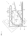
- FIG. 1 is a schematic cross-sectional view of a scanning device 1 according to an embodiment
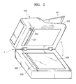
- FIG. 2 is a schematic perspective view of the scanning device 1, and illustrating a status where a document feeding unit 100 is opened.
- the scanning device 1 includes the document feeding unit 100 and a scanning unit 200.
- the scanning unit 200 includes a scanning member 210 to read images from a document.
- the scanning member 210 irradiates light to a document, and receives light reflected from the document to read images of the document.
- a contact type image sensor (CIS) or a charge coupled sensor (CCD), for example, may be used as the scanning member 210.
- the scanning device 1 may be a scanning device of a combined type, that is, obtaining by combining a flatbed type and a document feed type.
- the scanning unit 200 may include a platen glass 220 on which a document is placed to read images from the document in a flatbed type.
- the scanning unit 200 includes a scanning window 230 to read images from the document in the document feed type.
- the scanning window 230 may be, for example, a transparent member.
- an upper surface of the scanning window 230 may be located at the same level as that of an upper surface of the platen glass 220.
- the scanning member 210 may be disposed under the scanning window 230.
- the scanning member 210 may be transferred in a sub-scanning direction S, that is, a lengthwise direction of the document, by a transfer unit (not illustrated) under the platen glass 220.
- the platen glass 220 may need to be exposed to the outside in order to place a document on the platen glass 220.
- the document feeding unit 100 may be rotated with respect to the scanning unit 200. The document feeding unit 100 may be rotated between a first location where the document feeding unit 100 covers the scanning unit 200, and a second location where the scanning unit 200 is opened. When the document feeding unit 100 is located at the second location, the platen glass 220 is exposed to outside.
- the document feeding unit 100 moves the document so that the scanning member 210 may read an image recorded on the document, and discharges the document that has read.
- the document feeding unit 100 includes a document feeding path 300, and the scanning member 210 reads the image from the document that is fed.
- the document feeding path 300 may include a supply path 301, a scanning path 302, and a discharge path 303.
- the scanning member 210 may be disposed on the scanning path 302, and the image recorded on the document may be read by the scanning member 210 while the document passes through the scanning path 302.
- the supply path 301 is a path to supply the document to the scanning path 302, and the document loaded in a supply tray 401 may be supplied to the scanning path 302 via the supply path 301.
- the discharge path 303 is a path discharge the document that has passed through the scanning path 302.
- the document loaded in the supply tray 401 may be transferred along the supply path 301, the scanning path 302, and the discharge path 303, and discharged to a discharge tray 402.
- an additional scanning member 210a may be provided in the document feeding unit 100.
- the scanning unit 210 provided in the scanning unit 200 reads an image on a front surface of the document
- the scanning member 210a provided in the document feeding unit 100 reads an image on a rear surface of the document.
- the scanning member 210a may be located downstream of the scanning member 210 in a document feeding direction.
- a plurality of document feeding rollers to feed documents may be provided on the document feeding path 300.
- a pickup roller 311 pick up a document from the document feed tray 401, and supply rollers 312 and 313 transfer the picked document.
- Each of the supply rollers 312 and 313 may include a pair of rollers rotating while being engaged with each other to transfer the document.
- One of the pair of rollers may be a driving roller and the other may be a driven roller that is rotated by being compressed by the driving roller.
- the driven roller When the supply path 301 is opened in order to remove a paper jam, the driven roller may be separated from the driving roller or a compression between the driven roller and the driving roller may be released.
- An automatic document feed (ADF) unit 314 to separate a selected document may be disposed between the pickup roller 311 and the supply roller 312.
- the ADF unit 314 may include a first ADF roller 314a and a second ADF roller 314b that are engaged with each other to rotate in opposite directions to each other.
- the first ADF roller 314a rotates in a direction in which the document is transferred to the supply path 301, and the second ADF roller 314b rotates in opposite direction thereto. If two or more documents are supplied between the first and second ADF rollers 314a and 314b, the first and second ADF rollers 314a and 314b may separate only one document and supply the document to the supply roller 312.
- a frictional force between the plurality of documents may be less than that between the first ADF roller 314a and the document and between the second ADF roller 314b and the document. Therefore, the document contacting the first ADF roller 314a and the document beneath the above document slide along each other. The document contacting the first ADF roller 314a may be separated and transferred toward the supply roller 312.
- the configuration of the ADF unit 314 is not limited to the example illustrated in FIG. 1 , and the ADF unit 314 may have various structures.
- Feeding rollers 321 and 322 to transfer the document may be disposed on the scanning path 302 to face the scanning members 210 and 210a.
- the feeding roller 321 rotates while being elastically pressed against the scanning window 230 disposed in the scanning unit 200, and transfers the document supplied between the feeding roller 321 and the scanning window 230.
- the feeding roller 322 may be rotated while facing the scanning member 210a, and transfers the document supplied between the feeding roller 322 and the scanning member 210a.
- the scanning member 210a may be elastically compressed toward the feeding roller 322.
- a discharge roller 331 discharge the document, from which the reading operation is finished, may be disposed on the discharge path 303.
- the discharge roller 331 may include a driving roller and a driven roller that are rotated while being engaged with each other.
- one or more sensors to sense documents may be disposed on the supply path 301, the scanning path 302, and the discharge path 303.
- a configuration so a user of the scanning device 1 may rotate all, or some of, the document feeding rollers manually may be provided.
- a mechanism e.g., knob 500 may be exposed through a bottom surface of the document feeding unit 100.
- the knob 500 may be exposed to the outside, for example, when the document feeding unit 100 is rotated with respect to the read unit 200 and located at the second location.
- the knob 500 may be connected to the document feed rollers, for example, the supply rollers 311 and 312, the feeding rollers 321 and 322, and the discharge roller 331.
- the feeding rollers 321 and 322, and the discharge roller 331 may be connected with each other by a power connection unit such as a gear or a belt, the user may rotate the document feeding rollers by rotating the knob 500 and remove the document on the document feeding path 300.
- a power connection unit such as a gear or a belt
- an exemplary scanning device 1 includes a clutch unit that may selectively connect the knob 500 to the document feeding rollers.
- the knob 500 may be connected to one of the supply rollers 311 and 312, the feeding rollers 321 and 322, and the discharge roller 331.
- the scanning device 1 of an exemplary embodiment includes a cover 110 opening/closing a part of the document feeding path 300.
- the cover 110 may be located between a closed position where the supply path 301 is formed, and an opening position where the supply path 301 is opened.
- the supply path 301 may be partially or entirely opened.
- the cover 110 may be rotated as illustrated by broken lines 1000 of FIG. 1 to open the supply path 301.
- the supply path 301 may be opened by rotating the cover 110 to remove the jammed document.
- the first ADF roller 314a and the driven rollers of the supply rollers 312 and 313 may be rotated with the cover 110.
- the document in the supply path 301 may be easily removed.
- the feeding rollers 321 and 322 and the discharge roller 331 need to be rotated to remove the document when the jammed document exists on the scanning path 302 and the discharge path 303.
- the knob 500 may be connected to one of the feeding rollers 321 and 322 and the discharge roller 331.
- the knob 500 and the feeding roller 321 may be connected to each other via the clutch unit.
- the clutch unit selectively connects the knob 500 and the feeding roller 321 to each other in correspondence with the opening/closing of the cover 110.
- the knob 500 When the cover 110 is located at the closed position, the knob 500 may be disconnected from the feeding roller 321, and when the cover 110 is located at the opening position, the knob 500 may be connected to the feeding roller 321.
- FIG. 3 is an exploded perspective view of the clutch unit according to an embodiment.
- a first clutch member 520 and a second clutch member 530 are illustrated.
- the first clutch member 520 may be coupled to a rotary shaft of the feeding roller 321.
- the second clutch member 530 may be connected to the knob 500 to be rotated with the knob 500, and may be provided to be connected to/separated from the first clutch member 520.
- a support axis 511 that is coaxial with the rotary shaft of the feeding roller 321 may be provided in a bracket 510, and the knob 500 is rotatably coupled to the support axis 511.
- the knob 500 includes an extension axis 501 extending to be coaxial with the support axis 511, and the second clutch member 530 may be provided in the extension axis 501 to be slid in the extension axis 501 direction.
- the second clutch member 530 includes an insertion hole 532 that configures a pair with the extension axis 501.
- the extension axis 501 and the insertion hole 532 may be formed so that the knob 500 and the second clutch member 530 may be rotated with each other. That is, when rotating the knob 500, the second clutch member 530 is also rotated.
- the first and second clutch members 520 and 530 may respectively include first and second connection portions 521 and 531 that are complimentary members engaged with each other to transfer a rotating force.
- a first elastic member 540 applies an elastic force to the second clutch member 530 so that the first and second connection portions 521 and 531 may be slid in a direction of engaging with each other.
- the first elastic member 540 may be, for example, a compression coil spring having an end portion and the other end portion respectively supported by the knob 500 and the second clutch member 530.
- a sliding member 550 may be slid in correspondence with the opening/closing operations of the cover 110.
- the sliding member 550 may be provided on a frame of the document feeding unit 100 to be slidable.
- the sliding member 550 may be provided on the bracket 510 to be slidable.
- the sliding member 550 moves the second clutch member 530 to a connection position where the first and second connection portions 521 and 531 are engaged and a separation position where the first and second connection portions 521 and 531 are separated from each other, in correspondence with the opening/closing operations of the cover 110.
- the sliding member 550 includes a connection lever 552 that contacts the cover 110 and a push lever 551 pushing the second clutch member 530 to the separation position.
- the push lever 551 includes a contact portion 551a that slidably contacts the second clutch member 530 in order to move the second clutch member 530.
- the contact portion 551a may include an inclined surface that is inclined with respect to a sliding direction of the sliding member 550.
- the inclined surface may be a plane or a curved surface.
- a second elastic member 560 applies an elastic force to the sliding member 550 to be slid in a direction of moving the second clutch member 530 to the connection position.
- the second elastic member 560 may be, for example, a compression coil spring having an end portion and the other end portion respectively supported by the bracket 510 and the sliding member 550.
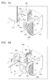
- FIG. 4A is a perspective view of a clutch unit when the cover 110 is closed
- FIG. 4B is a perspective view of a clutch unit when the cover 110 is opened.
- the cover 110 contacts the connection lever 552 of the sliding member 550 in a state where the cover 110 is closed
- the sliding member 550 is not slid toward the cover 110, that is, in a direction A1, even with the elastic force of the second elastic member 560.
- the second clutch member 530 is located at the separation position by the push lever 551. In this state, even when the feeding roller 321 is rotated by a driving motor (not illustrated), the second clutch member 530 and the knob 500 are not rotated.
- the sliding member 550 may be slid in the direction A1 by the elastic force of the second elastic member 560 as the cover 110 is rotated.
- the push lever 551 may be separated from the second clutch member 530, and the second clutch member 530 may be slid in a direction B1 toward the first clutch member 520 by the elastic force of the first elastic member 540 so that the first and second connection portions 521 and 531 are located at the connection position where they are engaged with each other. In this state, as illustrated in FIG.
- the feeding roller 321 and the other rollers connected to the feeding roller for example, the feeding roller 322 and the discharge roller 331, are rotated together, and the document existing in the scanning path 302 or the discharge path 303 may be discharged to the discharge tray 402.
- the driving rollers of the supply rollers 312 and 313 and the second ADF roller 314b may be rotated together.
- the cover 110 pushes the connection lever 551.
- the sliding member 550 is pushed by the cover 110 and is slid in an opposite direction to a direction of the elastic force of the second elastic member 560, that is, a direction A2 of FIG. 4A
- the push lever 551 pushes the second clutch member 530 in the opposite direction to the direction of the elastic force of the first elastic member 540, that is, the direction A2 of FIG. 4A , so that the first and second connection portions 521 and 531 are separated from each other.
- the knob 500 and the feeding roller 321 are disconnected from each other.
- the first and second connection portions 521 and 531 may be configured to be engaged with each other in a direction only.
- driving powers of the first and second connection portions 521 and 531 may be connected to each other only in a direction of discharging the document to the discharge tray 402, and may not be connected in an opposite direction.
- the first connection portion 521 extends in a rotating direction and protrudes in an axial direction.
- An end portion 521a of the first connection portion 521 is formed as an inclined surface that is slowly inclined in the rotating direction, and the other end portion 521b is formed as a rapidly inclined surface.
- the second connection portion 531 extends in the rotating direction and protrudes in the axial direction.
- An end portion 531a of the second connection portion 531 corresponds to the end portion 521a of the first connection portion 521, and is formed as an inclined surface that is softly inclined in the rotating direction.
- the other end portion 531b of the second connection portion 531 corresponds to the other end portion 521 b of the first connection portion 521, and is formed as a rapidly inclined surface.
- FIG. 5 is a schematic cross-sectional view of a scanning device 1a according to an embodiment
- FIG. 6 is an exemplary schematic perspective view of a scanning device 1a of FIG. 5 where a document feeding unit 100a is opened.
- the document may be reversed to perform a duplex-scanning operation.
- a document feed path 300a includes a supply path 301a, a scanning path 302a, the discharge path 305, and a reverse path 304 to reverse the document.
- a plurality of document feeding rollers to transfer documents may be disposed on the document feeding path 300a.
- the pickup roller 311 to pick a document loaded in the supply tray 401 and the supply roller 315 transfer the picked document may be disposed on the supply path 301a.
- the supply roller 315 may include a pair of rollers that are rotated while engaging with each other to transfer the document.
- One of the pair of rollers is a driving roller and the other is a driven roller that is rotated in a state of being compressed by the driving roller.
- the driven roller may be separated from the driving roller or a compression force onto the driven roller may be removed.
- the ADF unit 314 to separate the picked documents for example, one by one may be disposed between the pickup roller 311 and the supply roller 315.
- a scanning guide member 340 facing the scanning member 210 may be disposed on the scanning path 302a.
- the scanning guide member 340 may be pressed against a transparent window 230 by a weight of itself or the elastic member 341, and the document is transferred between the transparent window 230 and the scanning guide member 340.
- the feeding rollers 323 and 324 are disposed at opposite sides of the scanning member 210.
- Each of the feeding rollers 323 and 324 may include a driving roller and a driven roller that are rotated while engaging with each other.
- the discharge path 305 includes first, second, and third discharge paths 305a, 350b, and 305c.
- the first and second discharge paths 305a and 305b are branched from the scanning path 302a.
- a first switch member 351 to selectively connect the scanning path 302a to the first or second discharge path 305a or 305b is disposed at a branch portion 361 between the scanning path 302a and the first and second discharge paths 305a and 305b.
- the first switch member 351 is switched between a location to connect the scanning path 302a to the first discharge path 305a (location denoted by a dotted line) and a location to connect the scanning path 302a to the second discharge path 305b (location denoted by a solid line).
- the third discharge path 305c is connected to the first and second discharge paths 305a and 305b.
- a second switch member 352 is disposed at a branch portion 362 between the first discharge path 305a and the third discharge path 305c. The second switch member 352 is switched between a location to connect the first discharge path 305a to the third discharge path 305c to guide the document going backward along the first discharge path 305a to the second discharge path 305b (location denoted by a solid line) and a location to block the third discharge path 305c (location denoted by a dotted line).
- Discharge rollers 332a and 332b are respectively disposed on the first and second discharge paths 305a and 305b. Each of the discharge rollers 332a and 332b may include a driving roller and a driven roller that are rotated while engaging with each other.
- the reverse path 304 is branched from the scanning path 302a, and is connected to the supply path 301a. Also, the reverse path 304 is connected to the second discharge path 305b.
- a third switch member 353 is disposed at a branch portion 363 between the reverse path 304 and the scanning path 302a. The third switch member 353 is switched between a location to connect the scanning path 302a and the reverse path 304 (location denoted by a solid line) and a location to disconnect the scanning path 302a and the reverse path 304 (location denoted by a dotted line).
- a fourth switch member 354 is disposed at a branch portion 364 between the reverse path 304 and the second discharge path 305b.
- the fourth switch path 354 is switched between locations connect/disconnect the reverse path 304 and the second discharge path 305b.
- Reversing rollers 341 and 342 are respectively disposed on the reverse path 304.
- the reversing rollers 341 and 342 are respectively disposed at opposite sides of the branch portion 363.
- Each of the reversing rollers 341 and 342 includes a driving roller and a driven roller that are rotated while engaging with each other.
- a document loaded in the supply tray 401 may be withdrawn by the pickup roller 311 and the ADF unit 314 one by one, and may be supplied to the scanning path 302a via the supply path 301a.
- An image on the document may be scanned while the document passes through the scanning region where the scanning guide member 340 and the scanning member 210 face each other.
- the document from which the scanning operation is finished may be discharged to a first discharge tray 403 or a second discharge tray 404 via the first or second discharge path 305a or 305b. It may be determined which one of the trays 403 and 404 will receive the discharged document by adjusting the first, third, and fourth switch members 351, 353, and 354. After scanning a surface, the document discharged to the first or second discharge tray 403 or 404 is loaded in a face-down status, and thus, the document that is scanned first is loaded at a lowermost layer.
- the document may be transferred to the reverse path 304 after scanning the image on a front surface of the document.
- a fourth switch member 354 blocks the second discharge path 305b. If a rear end of the document passes through the branch portion 363, the third switch member 353 blocks the scanning path 302a.
- the reverse roller 342 rotates in a reverse direction, the document is transferred along the reverse path 342 and is supplied to the scanning path 302a via the supply path 301. In this process, the document may be turned over so that a rear surface of the document faces the scanning member 210. After scanning the rear surface of the document, the document may be discharged to the first discharge path 305a.
- the second switch member 352 may be switched to the location to connect the first discharge path 305a to the third discharge path 305c.
- the discharge roller 332a When the discharge roller 332a is rotated in a reverse direction, the document may be transferred along the third discharge path 305c and is discharged to the first discharge tray 403 via the second discharge path 305b.
- the document may be turned over during passing through the third discharge path 305c, and thus, the document discharged to the first discharge tray 403 after the duplex-scanning operation may be loaded in a face-down status, and the document that is scanned first is located at a lowermost layer.
- sensors to sense the document may be provided in the supply path 301a, the scanning path 302a, the discharge path 305, and the reverse path 304.
- a user may manually rotate the document feeding rollers.
- a knob 600 exposed from a bottom surface of a document feeding unit 100a is illustrated.
- the knob 600 is selectively connected to the rollers by a clutch unit.
- the scanning device 1 a of an exemplary embodiment includes covers 110a and 120 to open/close a part of a document feeding path 300a.
- the cover 110a opens/closes the supply path 301a.
- the cover 110a may be rotated to open the supply path 301a as illustrated by broken lines 5000 in FIG. 5 . Therefore, when double-feed documents or jammed document exists in the supply path 301a, the cover 110a may be rotated to open the supply path 301a and the jammed document may be removed.
- the cover 120 opens/closes a part of the scanning path 302a.
- the cover 120 of the present embodiment opens a downstream path of the scanning region.
- the clutch unit may selectively connect the knob 600 to the rollers in correspondence with the opening/closing operations of the cover 120.
- the knob 600 When the cover 120 is located at a closed position where the scanning path 302a is formed, the knob 600 may be disconnected from the feeding roller 323, and when the cover 120 is located at an opening position where the scanning path 302a is opened, the knob 600 may be connected to the feeding roller 323.
- FIG. 7 is an exploded perspective view of a clutch unit according to an embodiment.
- a first clutch member 620 and a second clutch member 630 are provided.
- the first clutch member 620 may be inserted in a rotary shaft of the feeding roller 323.
- the second clutch member 630 may be connected to the knob 600 to be rotated with the knob 600, and may be configured to approach to/ separate from the first clutch member 620.
- a support axis 611 that is coaxial with the rotary shaft of the feeding roller 321 may be provided on a bracket 610, and the knob 600 is rotatably inserted in the support axis 611.
- the knob 600 includes an extension axis 601 that is coaxial with the support axis 611 and extending toward the feeding roller 323, and the second clutch member 630 is provided on the extension axis 601 to be slid in the extension axis 601 direction.
- the second clutch member 630 includes an insertion hole 632 that forms a pair with the extension axis 601.
- the extension axis 601 and the insertion hole 632 may be formed so that the knob 600 and the second clutch member 630 may be rotated together. That is, when rotating the knob 600, the second clutch member 630 is also rotated.
- the first and second clutch members 620 and 630 respectively include first and second connection portions 621 and 631 that may be complementary members engaged with each other to transmit the rotating force.
- the first elastic member 640 may be disposed between the second clutch member 630 and the knob 600, and applies the elastic force to the second clutch member 630 so that the second clutch member 630 may be slid in a direction toward the location where the first and second connection portions 621 and 631 are engaged.
- the first elastic member 640 may be, for example, a compression coil spring having an end portion and the other end portion respectively supported by the first and second clutch members 620 and 630.
- the sliding member 650 may be slid in response to the opening/closing operations of the cover 120.
- the sliding member 650 may be provided on a frame of the document feeding unit 100a to be slid, although not illustrated in the drawings.
- the sliding member 650 moves the second clutch member 630 to a connection location where the first and second connection portions 621 and 631 are engaged with each other and a separation location where the first and second connection portions 621 and 631 are separated from each other, in correspondence with the opening/closing operations of the cover 120.
- the sliding member 650 includes a push lever 651 pushing the second clutch member 630 to the separation location.
- the push lever 651 includes a contact portion 651a that contacts the second clutch member 630 in order to move the second clutch member 630 to the separation location.
- the contact portion 651a may include an inclined surface that is inclined with respect to the sliding direction of the sliding member 650.
- the inclined surface may be a plane or a curved surface.
- the second elastic member 660 applies the elastic fore to the sliding member 650 so that the sliding member 650 may slide in a direction of moving the second clutch member 630 to the connection position.
- the second elastic member 660 may be, for example, a tension coil spring having an end portion and the other portion respectively supported by the cover 120 and the sliding member 650.
- a release member 670 may be coupled to the rotary shaft 121 of the cover 120, and is rotated with the cover 120 when the cover 120 rotates based on the rotary shaft 121 in order to open/close the scanning path 302a.
- the release member 670 pushes the sliding member 650 in an opposite direction in which the elastic force of the second elastic member 660 may be applied, when the cover 120 rotates to the location where the scanning path 302a may be closed.
- the second clutch member 630 may be pushed by the push lever 651 and is slid so that the first and second connection portions 621 and 631 are separated from each other.
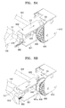
- FIG. 8A is an exemplary perspective view of a clutch unit in a state where the cover 120 is closed
- FIG. 8B is an exemplary perspective view of a clutch unit when the cover 120 is opened.
- the sliding member 650 contacts the release member 670 by the elastic force of the second elastic member 660 in a state where the cover 120 is closed.
- the push lever 651 may be disposed between the first and second clutch members 620 and 630 so that the first and second connection portions 621 and 631 are separated from each other. In this state, even when the feeding roller 323 is rotated by a driving motor (not illustrated), the second clutch member 630 and the knob 600 are not rotated.
- the release member 670 may be rotated to be apart from the sliding member 650, and the sliding member 650 may be slid toward the cover 120, that is, an arrow C1 direction of FIG. 8B , by the elastic force of the second elastic member 660.
- the push lever 651 may be separated from the second clutch member 630, and the second clutch member 630 may be slid toward the first clutch member 620, that is, an arrow D1 direction of FIG.
- the cover 120 may be closed, and, the release member 670 pushes the sliding member 650 in a direction opposite to the direction in which the elastic force of the second elastic member 660 is applied, that is, an arrow C2 direction of FIG. 8A . Since the sliding member 650 is slid by the release member 670, the push lever 651 pushes the second clutch member 630 in a direction opposite to the direction in which the elastic force of the first elastic member 640 is applied, that is, an arrow D2 direction of FIG. 8A , to separate the first and second connection portions 621 and 631 from each other.
- the knob 600 and the feeding roller 323 are disconnected from each other.
- the first and second connection portions 621 and 631 may be configured to be engaged with each other, for example, in only one direction, and the configurations may be the same as the first and second connection portions 521 and 531 illustrated in FIG. 3 .
- the knob 500 or 600 may be connected to the feeding rollers only when the jammed document has to be removed, and may be disconnected from the feeding rollers during the operation of the scanning device 1 or 1a. Accordingly, while the scanning device 1 or 1a operates, the knob 500 or 600 may not be rotated. Thus, operating noise may be reduced, and abrasion of the components may be reduced to improve the reliability of the scanning device.
- FIG. 9 is a schematic block diagram of an image forming apparatus according to an embodiment.
- a scanning device 3 and a printing unit 4 are provided.
- the printing unit 4 of the present embodiment is an electrophotographic printing unit that prints images on printing media in an electrophotographic method.
- the scanning device 3 may be located above the printing unit 4.
- the scanning device 3 may be the scanning device 1 illustrated in FIG. 1 or the scanning device 1a illustrated in FIG. 5 .
- the printing unit 4 includes a photosensitive drum 11, a charging roller 12, an exposure unit 20, a developing unit 30, and a transfer roller 40.
- the photosensitive drum 11 is an example of a photosensitive body on which an electrostatic latent image is formed, and includes a photosensitive layer having a photoconductivity formed on an outer circumference of a cylindrical metal pipe.
- the charging roller 12 is an example of a charger to charge a surface of the photosensitive drum 11 to a uniform potential. A corona charger (not illustrated) may be used instead of the charging roller 12.
- the exposure unit 20 irradiates light (L) that is modulated according to image information to the surface of the photosensitive drum 11, which is charged to a uniform potential, to form an electrostatic latent image.
- a laser scanning unit (LSU) that deflects light emitted from a laser diode in a main scanning direction by using a polygon mirror and scans the deflected light onto the photosensitive drum 11 may be used as the exposure unit 20.
- the developing unit 30 supplies a toner to the electrostatic latent image formed on the photosensitive drum 11 to develop the electrostatic latent image.
- the developing unit 30 accommodates a toner.
- a developing roller 13 supplies the toner to the electrostatic latent image formed on the photosensitive drum 11 to develop the electrostatic image as a visible toner image.
- An embodiment adopts a non-contact developing method, that is, a surface of the developing roller 13 may be separated hundreds of ⁇ m from the surface of the photosensitive drum 11. The above separation may be referred to as a developing gap.
- a developing bias voltage is applied to the developing roller 13, the toner is transferred and attached to the electrostatic latent image formed on the photosensitive drum 11 via the developing gap. If a contact type developing method is used, the developing roller 13 contacts the photosensitive drum 11.
- the developing unit 30 may include a supplying roller 14 to attach the toner to the developing roller 13.
- a supply bias voltage may be applied to the supplying roller 14 in order to attach the toner to the developing roller 13.
- a regulating member 15 regulates an amount of the toner attached to the surface of the developing roller 13.
- the regulating member 15 may be a regulating blade having a front edge that contacts the developing roller 13 with a predetermined pressure.
- a cleaning member 16 removes remaining toner and impurities from the surface of the photosensitive drum 11 before charging the photosensitive drum 11.
- the cleaning member 16 may be, for example, a cleaning blade having a front edge contacting the surface of the photosensitive drum 11.
- An agitator 17 conveys the toner to the developing roller 13. The agitator 17 agitates the toner to charge the toner to a predetermined potential.
- the transfer roller 40 is an example of a transfer unit that faces the surface of the photosensitive drum 11 to form a transfer nip.
- a transfer bias voltage may be applied to the transfer roller 40 in order to transfer the toner image formed on the surface of the photosensitive drum 11 onto a recording medium P.
- a corona transfer unit may be used instead of the transfer roller 40.
- the printing medium P on which an image is to be printed may be withdrawn from a paper cassette 51 by a pickup roller 52.
- the recording medium P may be supplied to a region where the transfer roller 40 and the photosensitive drum 11 face each other by a feeding roller 53.
- the toner image on the photosensitive drum 11 may be transferred onto the surface of the recording medium P by the transfer bias voltage applied to the transfer roller 40, and may be maintained on the surface of the recording medium P due to an electrostatic attraction.
- a fusing unit 60 applies heat and pressure to the toner image so that the toner image may be fused in the recording medium P, and thus, a permanent printing image is formed on the recording medium P.
- the fusing unit 60 may be configured so that a heating roller 61 including a heating unit 63 therein and a compression roller 62 are engaged to each other to form a fusing nip.
- the recording medium P passed through the fusing unit 60 is discharged to a discharge tray 55 by a discharge roller 54.
- a printing operation is an operation of printing images on a medium based on image information transmitted from an external host (not illustrated).
- the copying operation is an operation of reading image information from a document by using the scanning device 3 and transferring the read image information to the printing unit 4 to print the image on a medium.
- the scanning operation is an operation of reading image information from a document, for example, the read image information may be transmitted to a host (not illustrated). If there is a communication unit (not illustrated), a fax transmission function to transmit the read image information via a communication line such as a telephone line and a fax reception function to print image information received via the telephone line by using the printing unit 4 may be performed.
- a monochromatic electrophotographic printing unit 4 including one developing unit 30 is described; however, the embodiments are not limited thereto.
- four developing units 30 respectively accommodating cyan, magenta, yellow, and black toners, for example, may be adopted.
- a printing unit 4 may adopt another kind of image forming method, for example, an inkjet method or a thermal transfer method.
Landscapes
- Engineering & Computer Science (AREA)
- Multimedia (AREA)
- Signal Processing (AREA)
- Mechanical Engineering (AREA)
- Facsimiles In General (AREA)
- Sheets, Magazines, And Separation Thereof (AREA)
- Facsimile Scanning Arrangements (AREA)
- Manual Feeding Of Sheets (AREA)
Abstract
Description
- This application is related to, and claims the priority benefit of, Korean Patent Application No.
10-2013-0158681, filed on December 18, 2013 - One or more embodiments relate to a scanning device reading images from a document and an image forming apparatus including a scanning device.
- A scanning device is an apparatus to irradiate light onto a document and receiving light reflected from the document to read images recorded on the document. The scanning device may be classified as a flatbed type, in which a document may be located at a fixed position and a scanning member such as a contact type image sensor (CIS) or a charge coupled device (CCD) reads images while moving, a document feed type, in which a scanning member may be fixed at a location and a document is moved to be read, and a combined type thereof.
- The scanning device may be used as a single device, or as a multi-functional device combined with a printer including a printing unit to print images on printing media or a copying machine.
- In a case where a defect such as a paper jam or a double feed, that is, two or more documents conveyed simultaneously, occurs during a reading operation, one or more of the documents may need to be removed from a feeding path.
- One or more embodiments include a scanning device capable of removing a document when a defect in conveying documents occurs, and an image forming apparatus adopting the scanning device.
- Additional aspects will be set forth in part in the description which follows and, in part, will be apparent from the description, or may be learned by practice of the presented embodiments.
- According to the present invention there is provided an apparatus and method as set forth in the appended claims. Other features of the invention will be apparent from the dependent claims, and the description which follows.
- According to one or more embodiments, a scanning device includes document feeding rollers to convey a document along a document feeding path, a scanning member provided on the document feeding path to read images from the document, a cover to open and close a part of the document feeding path, a knob to manually rotate the document feeding rollers, and a clutch unit to selectively connect at least one of the document feeding rollers to the knob in correspondence with opening and closing operations of the cover.
- The clutch unit may disconnect the document feeding rollers and the knob from each other when the cover is located at a closed position, and may connect at least one of the document feeding rollers to the knob when the cover is located at an open position.
- The document feeding path may include a scanning path in which the scanning member is provided, a supply path to supply a document to the scanning path, and a discharge path to discharge the document that has passed through the scanning path, and the cover opens and closes the supply path.
- The document feeding path may include a scanning path in which the scanning member is provided, a supply path to supply a document to the scanning path, and a discharge path to discharge the document passed through the scanning path, and the cover opens and closes a part of the scanning path.
- The clutch unit may include a first clutch member provided on one of the document feeding rollers, and including a first connection portion; a second clutch member rotating with the knob, and including a second connection portion that is formed complementary with the first connection portion, and a sliding member to slide the second clutch member between a connecting position where the first and second connection portions are connected to each other and a separation position where the first and second connection portions are separated from each other, by the opening and closing operations of the cover.
- An extension axis that is coaxial with a rotary shaft of the document feeding roller having the first clutch member may be provided on the knob, and the second clutch member may be provided on the extension axis to be slid.
- The clutch unit may include a first elastic member to apply an elastic force to the second clutch member in a direction toward the connecting position, and the sliding member may push the second clutch member in a direction opposite to the elastic force of the first elastic member to move the second clutch member to the separation position when the cover is moved from the opened position to the closed position.
- The clutch unit may include a second elastic member applying an elastic force to the sliding member so that the sliding member slides in a direction of moving the second clutch member to the connection position.
- The scanning device may include a feeding roller provided in the scanning path to convey the document, and the clutch unit may selectively connect the knob to the feeding roller.
- The scanning device may include a discharge roller disposed on the discharge path discharge the document, and the discharge roller may be connected to the feeding roller and is rotated with the feeding roller when the knob is rotated.
- According to one or more embodiments, an image forming apparatus includes: the scanning device described above; and a printing unit to form an image on a recording medium.
- These and/or other aspects will become apparent and more readily appreciated from the following description of the embodiments, taken in conjunction with the accompanying drawings in which:
-
FIG. 1 is a schematic cross-sectional view of a scanning device according to an embodiment; -
FIG. 2 is a schematic perspective view of an exemplary scanning device, illustrating a state where a document feed unit is opened; -
FIG. 3 is an exploded perspective view of a clutch unit according to an embodiment; -
FIG. 4A is a perspective view of a clutch unit in a case where a cover is closed; -
FIG. 4B is a perspective view of a clutch unit in a case where a cover is opened; -
FIG. 5 is a schematic cross-sectional view of a scanning device according to an embodiment; -
FIG. 6 is a schematic perspective view of a scanning device in a case where a document feeding unit is opened; -
FIG. 7 is an exploded perspective view of a clutch unit according to an embodiment; -
FIG. 8A is a perspective view of a clutch unit when a cover is closed; -
FIG. 8B is a perspective view of a clutch unit when a cover is opened; and -
FIG. 9 is a schematic block diagram of an image forming apparatus according to an embodiment. - Reference will now be made in detail to embodiments, examples of which are illustrated in the accompanying drawings, wherein like reference numerals refer to the like elements throughout. In this regard, the embodiments may have different forms and should not be construed as being limited to the descriptions set forth herein. Accordingly, the embodiments are merely described below, by referring to the figures, to explain aspects of the present description. Expressions such as "at least one of," when preceding a list of elements, modify the entire list of elements and do not modify the individual elements of the list.
-
FIG. 1 is a schematic cross-sectional view of ascanning device 1 according to an embodiment, andFIG. 2 is a schematic perspective view of thescanning device 1, and illustrating a status where adocument feeding unit 100 is opened. Referring toFIGS. 1 and2 , thescanning device 1 includes thedocument feeding unit 100 and ascanning unit 200. - The
scanning unit 200 includes ascanning member 210 to read images from a document. Thescanning member 210 irradiates light to a document, and receives light reflected from the document to read images of the document. A contact type image sensor (CIS) or a charge coupled sensor (CCD), for example, may be used as thescanning member 210. - The
scanning device 1 may be a scanning device of a combined type, that is, obtaining by combining a flatbed type and a document feed type. Thescanning unit 200 may include aplaten glass 220 on which a document is placed to read images from the document in a flatbed type. Thescanning unit 200 includes ascanning window 230 to read images from the document in the document feed type. Thescanning window 230 may be, for example, a transparent member. As an example, an upper surface of thescanning window 230 may be located at the same level as that of an upper surface of theplaten glass 220. - In the document feed type, the
scanning member 210 may be disposed under thescanning window 230. In a case of the flatbed type, thescanning member 210 may be transferred in a sub-scanning direction S, that is, a lengthwise direction of the document, by a transfer unit (not illustrated) under theplaten glass 220. When the flatbed type is applied, theplaten glass 220 may need to be exposed to the outside in order to place a document on theplaten glass 220. As illustrated inFIG. 2 , thedocument feeding unit 100 may be rotated with respect to thescanning unit 200. Thedocument feeding unit 100 may be rotated between a first location where thedocument feeding unit 100 covers thescanning unit 200, and a second location where thescanning unit 200 is opened. When thedocument feeding unit 100 is located at the second location, theplaten glass 220 is exposed to outside. - The
document feeding unit 100 moves the document so that thescanning member 210 may read an image recorded on the document, and discharges the document that has read. Thedocument feeding unit 100 includes adocument feeding path 300, and thescanning member 210 reads the image from the document that is fed. Thedocument feeding path 300 may include asupply path 301, ascanning path 302, and adischarge path 303. The scanningmember 210 may be disposed on thescanning path 302, and the image recorded on the document may be read by the scanningmember 210 while the document passes through thescanning path 302. Thesupply path 301 is a path to supply the document to thescanning path 302, and the document loaded in asupply tray 401 may be supplied to thescanning path 302 via thesupply path 301. Thedischarge path 303 is a path discharge the document that has passed through thescanning path 302. The document loaded in thesupply tray 401 may be transferred along thesupply path 301, thescanning path 302, and thedischarge path 303, and discharged to adischarge tray 402. - In order to make a duplex reading possible with a single document feeding operation, an
additional scanning member 210a may be provided in thedocument feeding unit 100. Thescanning unit 210 provided in thescanning unit 200 reads an image on a front surface of the document, and thescanning member 210a provided in thedocument feeding unit 100 reads an image on a rear surface of the document. Thescanning member 210a may be located downstream of thescanning member 210 in a document feeding direction. - A plurality of document feeding rollers to feed documents may be provided on the
document feeding path 300. For example, apickup roller 311 pick up a document from thedocument feed tray 401, andsupply rollers supply rollers supply path 301 is opened in order to remove a paper jam, the driven roller may be separated from the driving roller or a compression between the driven roller and the driving roller may be released. An automatic document feed (ADF)unit 314 to separate a selected document, e.g., one by one may be disposed between thepickup roller 311 and thesupply roller 312. TheADF unit 314 may include afirst ADF roller 314a and asecond ADF roller 314b that are engaged with each other to rotate in opposite directions to each other. Thefirst ADF roller 314a rotates in a direction in which the document is transferred to thesupply path 301, and thesecond ADF roller 314b rotates in opposite direction thereto. If two or more documents are supplied between the first andsecond ADF rollers second ADF rollers supply roller 312. For example, if a plurality of documents are introduced between the first andsecond ADF rollers first ADF roller 314a and the document and between thesecond ADF roller 314b and the document. Therefore, the document contacting thefirst ADF roller 314a and the document beneath the above document slide along each other. The document contacting thefirst ADF roller 314a may be separated and transferred toward thesupply roller 312. The configuration of theADF unit 314 is not limited to the example illustrated inFIG. 1 , and theADF unit 314 may have various structures. - Feeding
rollers scanning path 302 to face thescanning members roller 321 rotates while being elastically pressed against thescanning window 230 disposed in thescanning unit 200, and transfers the document supplied between the feedingroller 321 and thescanning window 230. The feedingroller 322 may be rotated while facing thescanning member 210a, and transfers the document supplied between the feedingroller 322 and thescanning member 210a. Thescanning member 210a may be elastically compressed toward the feedingroller 322. - A
discharge roller 331 discharge the document, from which the reading operation is finished, may be disposed on thedischarge path 303. Thedischarge roller 331 may include a driving roller and a driven roller that are rotated while being engaged with each other. - Although not illustrated in the drawings, one or more sensors to sense documents may be disposed on the
supply path 301, thescanning path 302, and thedischarge path 303. - Since there are various reasons for generating a double-feed of the documents or a paper jam in the
scanning device 1, it may be difficult to completely prevent generation of the defective feed of documents. Therefore, a configuration to easily removing the documents in a case where the double-feed of the document or the paper jam occurs is necessary. Since a document may be stuck between the rollers, the document may be pulled in the document transfer direction or a direction opposite to the direction of transferring the document, and with a lot of force, and thus, the document may be torn. - According to an
exemplary scanning device 1 , a configuration so a user of thescanning device 1 may rotate all, or some of, the document feeding rollers manually may be provided. For example, referring toFIG. 2 , a mechanism, e.g.,knob 500 may be exposed through a bottom surface of thedocument feeding unit 100. Theknob 500 may be exposed to the outside, for example, when thedocument feeding unit 100 is rotated with respect to theread unit 200 and located at the second location. Theknob 500 may be connected to the document feed rollers, for example, thesupply rollers rollers discharge roller 331. Since all or some of thesupply rollers rollers discharge roller 331 may be connected with each other by a power connection unit such as a gear or a belt, the user may rotate the document feeding rollers by rotating theknob 500 and remove the document on thedocument feeding path 300. - If the
knob 500 is always connected to the document feeding rollers, theknob 500 may be also rotated while performing a reading operation. A large amount of load may be applied to a driving motor (not illustrated), and driving noise may generate and components may be worn out. Considering this, anexemplary scanning device 1 includes a clutch unit that may selectively connect theknob 500 to the document feeding rollers. - The
knob 500 may be connected to one of thesupply rollers rollers discharge roller 331. Thescanning device 1 of an exemplary embodiment includes acover 110 opening/closing a part of thedocument feeding path 300. For example, thecover 110 may be located between a closed position where thesupply path 301 is formed, and an opening position where thesupply path 301 is opened. When thecover 110 is located at the opening position, thesupply path 301 may be partially or entirely opened. Thecover 110 may be rotated as illustrated by broken lines 1000 ofFIG. 1 to open thesupply path 301. Thus, if the double-feed of the document or the paper jam occurs, thesupply path 301 may be opened by rotating thecover 110 to remove the jammed document. When thesupply path 301 is opened by rotating thecover 110, thefirst ADF roller 314a and the driven rollers of thesupply rollers cover 110. Thus, the document in thesupply path 301 may be easily removed. Since thescanning path 302 and thedischarge path 303 are not opened by the rotation of thecover 110, the feedingrollers discharge roller 331 need to be rotated to remove the document when the jammed document exists on thescanning path 302 and thedischarge path 303. To do this, for example, theknob 500 may be connected to one of the feedingrollers discharge roller 331. According to an exemplary embodiment, theknob 500 and the feedingroller 321 may be connected to each other via the clutch unit. The clutch unit selectively connects theknob 500 and the feedingroller 321 to each other in correspondence with the opening/closing of thecover 110. When thecover 110 is located at the closed position, theknob 500 may be disconnected from the feedingroller 321, and when thecover 110 is located at the opening position, theknob 500 may be connected to thefeeding roller 321. -
FIG. 3 is an exploded perspective view of the clutch unit according to an embodiment. Referring toFIG. 3 , a firstclutch member 520 and a secondclutch member 530 are illustrated. The firstclutch member 520 may be coupled to a rotary shaft of the feedingroller 321. The secondclutch member 530 may be connected to theknob 500 to be rotated with theknob 500, and may be provided to be connected to/separated from the firstclutch member 520. For example, asupport axis 511 that is coaxial with the rotary shaft of the feedingroller 321 may be provided in abracket 510, and theknob 500 is rotatably coupled to thesupport axis 511. Theknob 500 includes anextension axis 501 extending to be coaxial with thesupport axis 511, and the secondclutch member 530 may be provided in theextension axis 501 to be slid in theextension axis 501 direction. The secondclutch member 530 includes aninsertion hole 532 that configures a pair with theextension axis 501. Theextension axis 501 and theinsertion hole 532 may be formed so that theknob 500 and the secondclutch member 530 may be rotated with each other. That is, when rotating theknob 500, the secondclutch member 530 is also rotated. - The first and second
clutch members second connection portions elastic member 540 applies an elastic force to the secondclutch member 530 so that the first andsecond connection portions elastic member 540 may be, for example, a compression coil spring having an end portion and the other end portion respectively supported by theknob 500 and the secondclutch member 530. - A sliding
member 550 may be slid in correspondence with the opening/closing operations of thecover 110. Although not illustrated in the drawings, the slidingmember 550 may be provided on a frame of thedocument feeding unit 100 to be slidable. The slidingmember 550 may be provided on thebracket 510 to be slidable. The slidingmember 550 moves the secondclutch member 530 to a connection position where the first andsecond connection portions second connection portions cover 110. The slidingmember 550 includes aconnection lever 552 that contacts thecover 110 and apush lever 551 pushing the secondclutch member 530 to the separation position. Thepush lever 551 includes a contact portion 551a that slidably contacts the secondclutch member 530 in order to move the secondclutch member 530. The contact portion 551a may include an inclined surface that is inclined with respect to a sliding direction of the slidingmember 550. The inclined surface may be a plane or a curved surface. A secondelastic member 560 applies an elastic force to the slidingmember 550 to be slid in a direction of moving the secondclutch member 530 to the connection position. The secondelastic member 560 may be, for example, a compression coil spring having an end portion and the other end portion respectively supported by thebracket 510 and the slidingmember 550. -
FIG. 4A is a perspective view of a clutch unit when thecover 110 is closed, andFIG. 4B is a perspective view of a clutch unit when thecover 110 is opened. Referring toFIG. 4A , since thecover 110 contacts theconnection lever 552 of the slidingmember 550 in a state where thecover 110 is closed, the slidingmember 550 is not slid toward thecover 110, that is, in a direction A1, even with the elastic force of the secondelastic member 560. The secondclutch member 530 is located at the separation position by thepush lever 551. In this state, even when the feedingroller 321 is rotated by a driving motor (not illustrated), the secondclutch member 530 and theknob 500 are not rotated. - When the
cover 110 is rotated to the opening location as denoted by the broken line 1000 ofFIG. 1 in order to open a part of thedocument feeding path 300, for example, thesupply path 301, as illustrated inFIG. 4B , the slidingmember 550 may be slid in the direction A1 by the elastic force of the secondelastic member 560 as thecover 110 is rotated. Thepush lever 551 may be separated from the secondclutch member 530, and the secondclutch member 530 may be slid in a direction B1 toward the firstclutch member 520 by the elastic force of the firstelastic member 540 so that the first andsecond connection portions FIG. 2 , when thedocument feeding unit 100 is opened and theknob 500 exposed on the bottom surface of thedocument feeding unit 100 is rotated, the feedingroller 321 and the other rollers connected to the feeding roller, for example, the feedingroller 322 and thedischarge roller 331, are rotated together, and the document existing in thescanning path 302 or thedischarge path 303 may be discharged to thedischarge tray 402. The driving rollers of thesupply rollers second ADF roller 314b may be rotated together. - After discharging the document, when the
cover 110 is closed, thecover 110 pushes theconnection lever 551. The slidingmember 550 is pushed by thecover 110 and is slid in an opposite direction to a direction of the elastic force of the secondelastic member 560, that is, a direction A2 ofFIG. 4A , thepush lever 551 pushes the secondclutch member 530 in the opposite direction to the direction of the elastic force of the firstelastic member 540, that is, the direction A2 ofFIG. 4A , so that the first andsecond connection portions cover 110 is completely closed, as illustrated inFIG. 4A , theknob 500 and the feedingroller 321 are disconnected from each other. - The first and
second connection portions second connection portions discharge tray 402, and may not be connected in an opposite direction. To do this, referring toFIG. 3 , thefirst connection portion 521 extends in a rotating direction and protrudes in an axial direction. Anend portion 521a of thefirst connection portion 521 is formed as an inclined surface that is slowly inclined in the rotating direction, and theother end portion 521b is formed as a rapidly inclined surface. Thesecond connection portion 531 extends in the rotating direction and protrudes in the axial direction. An end portion 531a of thesecond connection portion 531 corresponds to theend portion 521a of thefirst connection portion 521, and is formed as an inclined surface that is softly inclined in the rotating direction. Theother end portion 531b of thesecond connection portion 531 corresponds to theother end portion 521 b of thefirst connection portion 521, and is formed as a rapidly inclined surface. When theknob 500 is rotated in a direction of discharging the document, theother end portion 521b of thefirst connection portion 521 and theother end portion 531b of thesecond connection portion 531 contact each other. Therefore, when the secondclutch member 530 is rotated, the firstclutch member 520 and the feedingroller 321 connected to the first clutch member 5210 are rotated so that the document is discharged to thedischarge tray 402. When theknob 500 is rotated in a direction opposite to the discharging direction of the document, theend portion 521a of thefirst connection portion 521 and the end portion 531a of thesecond connection portion 531 contact each other, and the secondclutch member 530 is pushed in a direction opposite to the direction in which the elastic force of the firstclutch member 540 is applied. Therefore, the rotating force of the secondclutch member 530 is not transmitted to the firstclutch member 520, and the feedingroller 321 does not rotate. -
FIG. 5 is a schematic cross-sectional view of ascanning device 1a according to an embodiment, andFIG. 6 is an exemplary schematic perspective view of ascanning device 1a ofFIG. 5 where adocument feeding unit 100a is opened. According to thescanning device 1a of an exemplary embodiment, the document may be reversed to perform a duplex-scanning operation. Referring toFIGS. 5 and6 , adocument feed path 300a includes asupply path 301a, ascanning path 302a, thedischarge path 305, and areverse path 304 to reverse the document. - A plurality of document feeding rollers to transfer documents may be disposed on the
document feeding path 300a. For example, thepickup roller 311 to pick a document loaded in thesupply tray 401 and thesupply roller 315 transfer the picked document may be disposed on thesupply path 301a. Thesupply roller 315 may include a pair of rollers that are rotated while engaging with each other to transfer the document. One of the pair of rollers is a driving roller and the other is a driven roller that is rotated in a state of being compressed by the driving roller. When thesupply path 301a is opened to remove a jammed document, the driven roller may be separated from the driving roller or a compression force onto the driven roller may be removed. TheADF unit 314 to separate the picked documents, for example, one by one may be disposed between thepickup roller 311 and thesupply roller 315. - A
scanning guide member 340 facing the scanningmember 210 may be disposed on thescanning path 302a. Thescanning guide member 340 may be pressed against atransparent window 230 by a weight of itself or theelastic member 341, and the document is transferred between thetransparent window 230 and thescanning guide member 340. Based on thescanning member 210, the feedingrollers scanning member 210. Each of the feedingrollers - The
discharge path 305 includes first, second, andthird discharge paths second discharge paths scanning path 302a. Afirst switch member 351 to selectively connect thescanning path 302a to the first orsecond discharge path branch portion 361 between thescanning path 302a and the first andsecond discharge paths first switch member 351 is switched between a location to connect thescanning path 302a to thefirst discharge path 305a (location denoted by a dotted line) and a location to connect thescanning path 302a to thesecond discharge path 305b (location denoted by a solid line). Thethird discharge path 305c is connected to the first andsecond discharge paths second switch member 352 is disposed at abranch portion 362 between thefirst discharge path 305a and thethird discharge path 305c. Thesecond switch member 352 is switched between a location to connect thefirst discharge path 305a to thethird discharge path 305c to guide the document going backward along thefirst discharge path 305a to thesecond discharge path 305b (location denoted by a solid line) and a location to block thethird discharge path 305c (location denoted by a dotted line).Discharge rollers second discharge paths discharge rollers - The
reverse path 304 is branched from thescanning path 302a, and is connected to thesupply path 301a. Also, thereverse path 304 is connected to thesecond discharge path 305b. Athird switch member 353 is disposed at abranch portion 363 between thereverse path 304 and thescanning path 302a. Thethird switch member 353 is switched between a location to connect thescanning path 302a and the reverse path 304 (location denoted by a solid line) and a location to disconnect thescanning path 302a and the reverse path 304 (location denoted by a dotted line). Afourth switch member 354 is disposed at abranch portion 364 between thereverse path 304 and thesecond discharge path 305b. Thefourth switch path 354 is switched between locations connect/disconnect thereverse path 304 and thesecond discharge path 305b. Reversingrollers reverse path 304. The reversingrollers branch portion 363. Each of the reversingrollers - Exemplary scanning operations performed by the above configuration are described. A document loaded in the
supply tray 401 may be withdrawn by thepickup roller 311 and theADF unit 314 one by one, and may be supplied to thescanning path 302a via thesupply path 301a. An image on the document may be scanned while the document passes through the scanning region where thescanning guide member 340 and thescanning member 210 face each other. The document from which the scanning operation is finished may be discharged to afirst discharge tray 403 or asecond discharge tray 404 via the first orsecond discharge path trays fourth switch members second discharge tray - If a duplex-scanning operation is performed, the document may be transferred to the
reverse path 304 after scanning the image on a front surface of the document. Afourth switch member 354 blocks thesecond discharge path 305b. If a rear end of the document passes through thebranch portion 363, thethird switch member 353 blocks thescanning path 302a. When thereverse roller 342 rotates in a reverse direction, the document is transferred along thereverse path 342 and is supplied to thescanning path 302a via thesupply path 301. In this process, the document may be turned over so that a rear surface of the document faces thescanning member 210. After scanning the rear surface of the document, the document may be discharged to thefirst discharge path 305a. When a rear end of the document passes through thebranch portion 362, thesecond switch member 352 may be switched to the location to connect thefirst discharge path 305a to thethird discharge path 305c. When thedischarge roller 332a is rotated in a reverse direction, the document may be transferred along thethird discharge path 305c and is discharged to thefirst discharge tray 403 via thesecond discharge path 305b. The document may be turned over during passing through thethird discharge path 305c, and thus, the document discharged to thefirst discharge tray 403 after the duplex-scanning operation may be loaded in a face-down status, and the document that is scanned first is located at a lowermost layer. - Although not illustrated in the drawings, sensors to sense the document may be provided in the
supply path 301a, thescanning path 302a, thedischarge path 305, and thereverse path 304. - According to the
scanning device 1a of the embodiment, a user may manually rotate the document feeding rollers. As an example, referring toFIG. 6 , aknob 600 exposed from a bottom surface of adocument feeding unit 100a is illustrated. Theknob 600 is selectively connected to the rollers by a clutch unit. - The
scanning device 1 a of an exemplary embodiment includescovers document feeding path 300a. For example, thecover 110a opens/closes thesupply path 301a. Thecover 110a may be rotated to open thesupply path 301a as illustrated by broken lines 5000 inFIG. 5 . Therefore, when double-feed documents or jammed document exists in thesupply path 301a, thecover 110a may be rotated to open thesupply path 301a and the jammed document may be removed. Thecover 120 opens/closes a part of thescanning path 302a. Thecover 120 of the present embodiment opens a downstream path of the scanning region. The clutch unit may selectively connect theknob 600 to the rollers in correspondence with the opening/closing operations of thecover 120. When thecover 120 is located at a closed position where thescanning path 302a is formed, theknob 600 may be disconnected from the feedingroller 323, and when thecover 120 is located at an opening position where thescanning path 302a is opened, theknob 600 may be connected to thefeeding roller 323. -
FIG. 7 is an exploded perspective view of a clutch unit according to an embodiment. Referring toFIG. 7 , a firstclutch member 620 and a secondclutch member 630 are provided. The firstclutch member 620 may be inserted in a rotary shaft of the feedingroller 323. The secondclutch member 630 may be connected to theknob 600 to be rotated with theknob 600, and may be configured to approach to/ separate from the firstclutch member 620. For example, asupport axis 611 that is coaxial with the rotary shaft of the feedingroller 321 may be provided on abracket 610, and theknob 600 is rotatably inserted in thesupport axis 611. Theknob 600 includes anextension axis 601 that is coaxial with thesupport axis 611 and extending toward the feedingroller 323, and the secondclutch member 630 is provided on theextension axis 601 to be slid in theextension axis 601 direction. The secondclutch member 630 includes aninsertion hole 632 that forms a pair with theextension axis 601. Theextension axis 601 and theinsertion hole 632 may be formed so that theknob 600 and the secondclutch member 630 may be rotated together. That is, when rotating theknob 600, the secondclutch member 630 is also rotated. - The first and second
clutch members elastic member 640 may be disposed between the secondclutch member 630 and theknob 600, and applies the elastic force to the secondclutch member 630 so that the secondclutch member 630 may be slid in a direction toward the location where the first and second connection portions 621 and 631 are engaged. The firstelastic member 640 may be, for example, a compression coil spring having an end portion and the other end portion respectively supported by the first and secondclutch members - The sliding
member 650 may be slid in response to the opening/closing operations of thecover 120. The slidingmember 650 may be provided on a frame of thedocument feeding unit 100a to be slid, although not illustrated in the drawings. The slidingmember 650 moves the secondclutch member 630 to a connection location where the first and second connection portions 621 and 631 are engaged with each other and a separation location where the first and second connection portions 621 and 631 are separated from each other, in correspondence with the opening/closing operations of thecover 120. The slidingmember 650 includes apush lever 651 pushing the secondclutch member 630 to the separation location. Thepush lever 651 includes acontact portion 651a that contacts the secondclutch member 630 in order to move the secondclutch member 630 to the separation location. Thecontact portion 651a may include an inclined surface that is inclined with respect to the sliding direction of the slidingmember 650. The inclined surface may be a plane or a curved surface. - The second
elastic member 660 applies the elastic fore to the slidingmember 650 so that the slidingmember 650 may slide in a direction of moving the secondclutch member 630 to the connection position. The secondelastic member 660 may be, for example, a tension coil spring having an end portion and the other portion respectively supported by thecover 120 and the slidingmember 650. - A
release member 670 may be coupled to therotary shaft 121 of thecover 120, and is rotated with thecover 120 when thecover 120 rotates based on therotary shaft 121 in order to open/close thescanning path 302a. Therelease member 670 pushes the slidingmember 650 in an opposite direction in which the elastic force of the secondelastic member 660 may be applied, when thecover 120 rotates to the location where thescanning path 302a may be closed. Accordingly, the secondclutch member 630 may be pushed by thepush lever 651 and is slid so that the first and second connection portions 621 and 631 are separated from each other. -
FIG. 8A is an exemplary perspective view of a clutch unit in a state where thecover 120 is closed, andFIG. 8B is an exemplary perspective view of a clutch unit when thecover 120 is opened. Referring toFIG. 8A , the slidingmember 650 contacts therelease member 670 by the elastic force of the secondelastic member 660 in a state where thecover 120 is closed. Thepush lever 651 may be disposed between the first and secondclutch members roller 323 is rotated by a driving motor (not illustrated), the secondclutch member 630 and theknob 600 are not rotated. - When the
document feeding unit 100a is opened as illustrated inFIG. 6 and thecover 120 is rotated as denoted by the broken lines 5000 inFIG. 5 in order to open a part of thedocument feeding path 300a, for example, thescanning path 302a, therelease member 670 may be rotated to be apart from the slidingmember 650, and the slidingmember 650 may be slid toward thecover 120, that is, an arrow C1 direction ofFIG. 8B , by the elastic force of the secondelastic member 660. Thepush lever 651 may be separated from the secondclutch member 630, and the secondclutch member 630 may be slid toward the firstclutch member 620, that is, an arrow D1 direction ofFIG. 8B , by the elastic force of the firstelastic member 640, and the first and second connection portions 621 and 631 are engaged with each other. In this state, when theknob 600 exposed on the bottom surface of thedocument feeding unit 100 is rotated, the feedingroller 323 and the other rollers connected thereto, for example, the feedingroller 324, thedischarge rollers reverse rollers scanning path 302a, thedischarge path 305, or thereverse path 304 may be discharged to the first orsecond discharge tray - After discharging the document, the
cover 120 may be closed, and, therelease member 670 pushes the slidingmember 650 in a direction opposite to the direction in which the elastic force of the secondelastic member 660 is applied, that is, an arrow C2 direction ofFIG. 8A . Since the slidingmember 650 is slid by therelease member 670, thepush lever 651 pushes the secondclutch member 630 in a direction opposite to the direction in which the elastic force of the firstelastic member 640 is applied, that is, an arrow D2 direction ofFIG. 8A , to separate the first and second connection portions 621 and 631 from each other. When thecover 120 is completely closed, as illustrated inFIG. 8A , theknob 600 and the feedingroller 323 are disconnected from each other. - The first and second connection portions 621 and 631 may be configured to be engaged with each other, for example, in only one direction, and the configurations may be the same as the first and
second connection portions FIG. 3 . - According to the
scanning device knob scanning device scanning device knob -
FIG. 9 is a schematic block diagram of an image forming apparatus according to an embodiment. Referring toFIG. 9 , ascanning device 3 and aprinting unit 4 are provided. Theprinting unit 4 of the present embodiment is an electrophotographic printing unit that prints images on printing media in an electrophotographic method. Thescanning device 3 may be located above theprinting unit 4. Thescanning device 3 may be thescanning device 1 illustrated inFIG. 1 or thescanning device 1a illustrated inFIG. 5 . - The
printing unit 4 includes aphotosensitive drum 11, a chargingroller 12, anexposure unit 20, a developingunit 30, and atransfer roller 40. Thephotosensitive drum 11 is an example of a photosensitive body on which an electrostatic latent image is formed, and includes a photosensitive layer having a photoconductivity formed on an outer circumference of a cylindrical metal pipe. The chargingroller 12 is an example of a charger to charge a surface of thephotosensitive drum 11 to a uniform potential. A corona charger (not illustrated) may be used instead of the chargingroller 12. - The
exposure unit 20 irradiates light (L) that is modulated according to image information to the surface of thephotosensitive drum 11, which is charged to a uniform potential, to form an electrostatic latent image. A laser scanning unit (LSU) that deflects light emitted from a laser diode in a main scanning direction by using a polygon mirror and scans the deflected light onto thephotosensitive drum 11 may be used as theexposure unit 20. - The developing
unit 30 supplies a toner to the electrostatic latent image formed on thephotosensitive drum 11 to develop the electrostatic latent image. The developingunit 30 accommodates a toner. A developing roller 13 supplies the toner to the electrostatic latent image formed on thephotosensitive drum 11 to develop the electrostatic image as a visible toner image. An embodiment adopts a non-contact developing method, that is, a surface of the developing roller 13 may be separated hundreds of µm from the surface of thephotosensitive drum 11. The above separation may be referred to as a developing gap. When a developing bias voltage is applied to the developing roller 13, the toner is transferred and attached to the electrostatic latent image formed on thephotosensitive drum 11 via the developing gap. If a contact type developing method is used, the developing roller 13 contacts thephotosensitive drum 11. The developingunit 30 may include a supplyingroller 14 to attach the toner to the developing roller 13. A supply bias voltage may be applied to the supplyingroller 14 in order to attach the toner to the developing roller 13. A regulatingmember 15 regulates an amount of the toner attached to the surface of the developing roller 13. The regulatingmember 15 may be a regulating blade having a front edge that contacts the developing roller 13 with a predetermined pressure. A cleaningmember 16 removes remaining toner and impurities from the surface of thephotosensitive drum 11 before charging thephotosensitive drum 11. The cleaningmember 16 may be, for example, a cleaning blade having a front edge contacting the surface of thephotosensitive drum 11. Anagitator 17 conveys the toner to the developing roller 13. Theagitator 17 agitates the toner to charge the toner to a predetermined potential. - The
transfer roller 40 is an example of a transfer unit that faces the surface of thephotosensitive drum 11 to form a transfer nip. A transfer bias voltage may be applied to thetransfer roller 40 in order to transfer the toner image formed on the surface of thephotosensitive drum 11 onto a recording medium P. A corona transfer unit may be used instead of thetransfer roller 40. - The printing medium P on which an image is to be printed may be withdrawn from a
paper cassette 51 by apickup roller 52. The recording medium P may be supplied to a region where thetransfer roller 40 and thephotosensitive drum 11 face each other by a feedingroller 53. The toner image on thephotosensitive drum 11 may be transferred onto the surface of the recording medium P by the transfer bias voltage applied to thetransfer roller 40, and may be maintained on the surface of the recording medium P due to an electrostatic attraction. - A fusing
unit 60 applies heat and pressure to the toner image so that the toner image may be fused in the recording medium P, and thus, a permanent printing image is formed on the recording medium P. The fusingunit 60 may be configured so that aheating roller 61 including aheating unit 63 therein and acompression roller 62 are engaged to each other to form a fusing nip. The recording medium P passed through the fusingunit 60 is discharged to adischarge tray 55 by adischarge roller 54. - According to the image forming apparatus described above, a printing operation, a copying operation, and a scanning operation may be performed. The printing operation is an operation of printing images on a medium based on image information transmitted from an external host (not illustrated). The copying operation is an operation of reading image information from a document by using the
scanning device 3 and transferring the read image information to theprinting unit 4 to print the image on a medium. The scanning operation is an operation of reading image information from a document, for example, the read image information may be transmitted to a host (not illustrated). If there is a communication unit (not illustrated), a fax transmission function to transmit the read image information via a communication line such as a telephone line and a fax reception function to print image information received via the telephone line by using theprinting unit 4 may be performed. - In the above described embodiments, a monochromatic
electrophotographic printing unit 4 including one developingunit 30 is described; however, the embodiments are not limited thereto. In a case of a full-color electrophotographic printing unit, four developingunits 30 respectively accommodating cyan, magenta, yellow, and black toners, for example, may be adopted. Aprinting unit 4 may adopt another kind of image forming method, for example, an inkjet method or a thermal transfer method. - It should be understood that the exemplary embodiments described therein should be considered in a descriptive sense only and not for purposes of limitation. Descriptions of features or aspects within each embodiment should typically be considered as available for other similar features or aspects in other embodiments.
- While one or more embodiments have been described with reference to the figures, it will be understood by those of ordinary skill in the art that various changes in form and details may be made therein without departing from the spirit and scope as defined by the following claims.
Claims (12)
- A scanning device comprising:document feeding rollers (311/312/321/322/331) to convey a document along a document feeding path (300);a scanning member (210) provided on the document feeding path (300) to read images from the document;a cover (110) to open and close a part of the document feeding path (300);a knob (500) to manually rotate at least one of the document feeding rollers (311/312/321/322/331); anda clutch unit (520/530) to selectively connect at least one of the document feeding rollers (311/312/321/322/331) to the knob (500) in correspondence with opening and closing operations of the cover.
- The scanning device of claim 1, wherein the clutch unit is operable to disconnect the document feeding rollers and the knob from each other when the cover is located at a closed position, and to connect at least one of the document feeding rollers to the knob when the cover is located at an open position.
- The scanning device of claim 2, wherein the document feeding path comprises a scanning path in which the scanning member is provided, a supply path to supply a document to the scanning path, and a discharge path to discharge the document that has passed through the scanning path, and the cover opens and closes the supply path.
- The scanning device of claim 2, wherein the document feeding path comprises a scanning path in which the scanning member is provided, a supply path to supply a document to the scanning path, and a discharge path to discharge the document passed through the scanning path, and the cover opens and closes a part of the scanning path.
- The scanning device of any one of claims 2 to 4, wherein the clutch unit comprises:a first clutch member provided on one of the document feeding rollers, and comprising a first connection portion;a second clutch member rotating with the knob, and comprising a second connection portion that is formed complementary with the first connection portion; anda sliding member to slide the second clutch member between a connecting position where the first and second connection portions are connected to each other and a separation position where the first and second connection portions are separated from each other, by the opening and closing operations of the cover.
- The scanning device of claim 5, wherein an extension axis that is coaxial with a rotary shaft of the document feeding roller having the first clutch member is provided on the knob, and the second clutch member is provided on the extension axis to be slid.
- The scanning device of claim 5 or claim 6, wherein the clutch unit further comprises a first elastic member to apply an elastic force to the second clutch member in a direction toward the connecting position, and
the sliding member is operable to push the second clutch member in a direction opposite to the elastic force of the first elastic member to move the second clutch member to the separation position when the cover is moved from the opened position to the closed position. - The scanning device of claim 7, wherein the clutch unit further comprises a second elastic member applying an elastic force to the sliding member so that the sliding member slides in a direction of moving the second clutch member to the connection position.
- The scanning device of any one of claims 2 to 8, wherein the document feeding path comprises a scanning path in which the scanning member is provided, the scanning device further comprises a feeding roller provided in the scanning path to convey the document, and the clutch unit selectively connects the knob to the feeding roller.
- The scanning device of claim 9, wherein the document feeding path comprises a discharge path to discharge the document passed through the scanning path, the scanning device further comprises a discharge roller disposed on the discharge path to discharge the document, and the discharge roller is connected to the feeding roller and is rotated with the feeding roller when the knob is rotated.
- An image forming apparatus comprising:a scanning device (1)as claimed in any one of claims 1 to 10; anda printing unit to form an image on a recording medium.
- An apparatus comprising:document feeding rollers to convey a document along a document feeding path;a cover to open and close at least a part of the document feeding path;a mechanism to rotate the document feeding rollers; anda clutch unit to selectively connect at least one of the document feeding rollers to the mechanism in correspondence with opening and closing operations of the cover.
Applications Claiming Priority (1)
| Application Number | Priority Date | Filing Date | Title |
|---|---|---|---|
| KR1020130158681A KR20150071537A (en) | 2013-12-18 | 2013-12-18 | scanner device and image forming apparatus adopting the same |
Publications (3)
| Publication Number | Publication Date |
|---|---|
| EP2887630A2 true EP2887630A2 (en) | 2015-06-24 |
| EP2887630A3 EP2887630A3 (en) | 2015-09-30 |
| EP2887630B1 EP2887630B1 (en) | 2020-05-06 |
Family
ID=51302889
Family Applications (1)
| Application Number | Title | Priority Date | Filing Date |
|---|---|---|---|
| EP14177985.0A Active EP2887630B1 (en) | 2013-12-18 | 2014-07-22 | Scanning device and image forming apparatus to convey a document |
Country Status (5)
| Country | Link |
|---|---|
| US (1) | US9522796B2 (en) |
| EP (1) | EP2887630B1 (en) |
| KR (1) | KR20150071537A (en) |
| CN (1) | CN104735291B (en) |
| WO (1) | WO2015093701A1 (en) |
Families Citing this family (7)
| Publication number | Priority date | Publication date | Assignee | Title |
|---|---|---|---|---|
| JP6030608B2 (en) * | 2014-07-30 | 2016-11-24 | Necプラットフォームズ株式会社 | Paper sheet transport device |
| JP6800615B2 (en) * | 2016-05-31 | 2020-12-16 | キヤノン株式会社 | Sheet transfer device, image reader and image forming device |
| JP6737004B2 (en) * | 2016-06-24 | 2020-08-05 | 沖電気工業株式会社 | Medium processing device and medium transaction device |
| US10931841B2 (en) * | 2018-06-27 | 2021-02-23 | Canon Kabushiki Kaisha | Sheet conveying apparatus and image scanning apparatus |
| JP7232145B2 (en) * | 2019-07-19 | 2023-03-02 | シャープ株式会社 | Document feeder and image forming device |
| JP7718213B2 (en) * | 2021-09-30 | 2025-08-05 | セイコーエプソン株式会社 | Image reading device |
| JP2024031520A (en) * | 2022-08-26 | 2024-03-07 | セイコーエプソン株式会社 | Media transport device, recording system |
Family Cites Families (22)
| Publication number | Priority date | Publication date | Assignee | Title |
|---|---|---|---|---|
| JPH03115036A (en) | 1989-09-29 | 1991-05-16 | Konica Corp | Automatic document transport device |
| KR930010296B1 (en) | 1990-12-12 | 1993-10-16 | 대우통신 주식회사 | Analog trunk and premises broadcasting simultaneous reception circuit in electronic switchboard. |
| KR940011861B1 (en) * | 1992-08-06 | 1994-12-27 | 삼성전자 주식회사 | Power interrupter for jam removal of the fuser unit |
| JPH1026853A (en) * | 1996-07-11 | 1998-01-27 | Mita Ind Co Ltd | Image forming machine |
| JPH1091053A (en) | 1996-09-13 | 1998-04-10 | Canon Inc | Image forming device |
| JPH1124434A (en) * | 1997-06-30 | 1999-01-29 | Ricoh Co Ltd | Drive contact / separation mechanism |
| DE10023614A1 (en) | 2000-05-15 | 2001-11-22 | Nexpress Solutions Llc | Device for the manual exchange of a roller of a duplicating device |
| JP3969629B2 (en) * | 2001-03-21 | 2007-09-05 | 京セラ株式会社 | Fixing device in image forming apparatus |
| JP2003072978A (en) * | 2001-09-07 | 2003-03-12 | Ricoh Co Ltd | Imaging device |
| JP3640955B2 (en) * | 2003-07-24 | 2005-04-20 | シャープ株式会社 | Document conveying device, document reading device, and image forming apparatus |
| KR100744066B1 (en) | 2005-06-27 | 2007-07-30 | 삼성전자주식회사 | Power transfer device of the image forming machine, an image forming apparatus having the same, and a power transmission method of the image forming machine |
| JP5078395B2 (en) * | 2006-03-31 | 2012-11-21 | キヤノン株式会社 | Sheet conveying apparatus, sheet processing apparatus, and image forming apparatus |
| TW200806495A (en) | 2006-07-17 | 2008-02-01 | Asia Optical Co Inc | Automatic paper feeder capable of eliminating paper jammed |
| TWI320395B (en) | 2007-02-09 | 2010-02-11 | Primax Electronics Ltd | An automatic duplex document feeder with a function of releasing paper jam |
| KR101253573B1 (en) | 2007-03-12 | 2013-04-11 | 삼성전자주식회사 | Image scanning device, image forming apparatus having the same and image reading method |
| KR101430933B1 (en) | 2007-07-24 | 2014-08-18 | 삼성전자 주식회사 | Image reading apparatus and image forming apparatus having the same |
| JP5446533B2 (en) | 2009-07-15 | 2014-03-19 | 富士ゼロックス株式会社 | Document feeder and image forming apparatus |
| JP5460410B2 (en) | 2010-03-26 | 2014-04-02 | 京セラドキュメントソリューションズ株式会社 | Jam processing apparatus and image forming apparatus |
| JP2012035942A (en) | 2010-08-04 | 2012-02-23 | Sharp Corp | Image forming apparatus |
| JP5704973B2 (en) * | 2011-03-08 | 2015-04-22 | ニスカ株式会社 | Sheet transport device |
| KR101813640B1 (en) | 2011-07-13 | 2017-12-29 | 에스프린팅솔루션 주식회사 | Scanner device and multifunction apparatus adopting the same |
| JP5994316B2 (en) * | 2012-03-22 | 2016-09-21 | 富士ゼロックス株式会社 | Opening and closing device, image forming apparatus |
-
2013
- 2013-12-18 KR KR1020130158681A patent/KR20150071537A/en not_active Withdrawn
-
2014
- 2014-06-04 US US14/295,747 patent/US9522796B2/en not_active Expired - Fee Related
- 2014-06-26 WO PCT/KR2014/005673 patent/WO2015093701A1/en not_active Ceased
- 2014-07-22 EP EP14177985.0A patent/EP2887630B1/en active Active
- 2014-09-04 CN CN201410448462.XA patent/CN104735291B/en active Active
Non-Patent Citations (1)
| Title |
|---|
| None |
Also Published As
| Publication number | Publication date |
|---|---|
| KR20150071537A (en) | 2015-06-26 |
| CN104735291B (en) | 2018-11-23 |
| EP2887630B1 (en) | 2020-05-06 |
| US9522796B2 (en) | 2016-12-20 |
| CN104735291A (en) | 2015-06-24 |
| EP2887630A3 (en) | 2015-09-30 |
| WO2015093701A1 (en) | 2015-06-25 |
| US20150172491A1 (en) | 2015-06-18 |
Similar Documents
| Publication | Publication Date | Title |
|---|---|---|
| EP2887630B1 (en) | Scanning device and image forming apparatus to convey a document | |
| US9549094B2 (en) | Scanning apparatus and image forming apparatus employing the same | |
| CN102467016B (en) | developer conveying device and image forming apparatus | |
| US8320798B2 (en) | Sheet conveying device and image forming apparatus | |
| CN109715537B (en) | Paper feeding apparatus, paper processing apparatus using the same, and image forming apparatus | |
| US9108818B2 (en) | Sheet discharger and image forming apparatus including same | |
| JP2012194331A (en) | Fixing device and image forming apparatus | |
| US8433234B2 (en) | Image forming apparatus and method thereof | |
| JP2006258920A (en) | Waste toner recovery device | |
| US20100054825A1 (en) | Image forming apparatus | |
| US7418220B2 (en) | Image recording apparatus | |
| KR102164239B1 (en) | Scanner device and image forming apparatus adopting the same | |
| JP7232145B2 (en) | Document feeder and image forming device | |
| WO2024043943A1 (en) | Structure for opening and closing sensor unit for image quality calibration | |
| JP2018054681A (en) | Opening / closing mechanism and image forming apparatus | |
| US9785108B1 (en) | Image forming apparatus | |
| US11099510B2 (en) | Presser, fixing device, and image forming apparatus | |
| JP2008256921A (en) | Waste toner recovery device for full-color image forming device | |
| JP5194966B2 (en) | Image forming apparatus | |
| JP2009091054A (en) | Paper conveying apparatus and image forming apparatus | |
| JP6807048B2 (en) | Sheet material transfer device, image reader and image forming device | |
| JP4230138B2 (en) | Image forming apparatus | |
| JP2022082864A (en) | Image forming apparatus | |
| JP2020193060A (en) | Drive coupling device | |
| JP2009181072A (en) | RECORDING MEDIUM CONVEYING DEVICE, TRANSFER DEVICE, AND IMAGE FORMING DEVICE |
Legal Events
| Date | Code | Title | Description |
|---|---|---|---|
| PUAI | Public reference made under article 153(3) epc to a published international application that has entered the european phase |
Free format text: ORIGINAL CODE: 0009012 |
|
| 17P | Request for examination filed |
Effective date: 20140722 |
|
| AK | Designated contracting states |
Kind code of ref document: A2 Designated state(s): AL AT BE BG CH CY CZ DE DK EE ES FI FR GB GR HR HU IE IS IT LI LT LU LV MC MK MT NL NO PL PT RO RS SE SI SK SM TR |
|
| AX | Request for extension of the european patent |
Extension state: BA ME |
|
| PUAL | Search report despatched |
Free format text: ORIGINAL CODE: 0009013 |
|
| AK | Designated contracting states |
Kind code of ref document: A3 Designated state(s): AL AT BE BG CH CY CZ DE DK EE ES FI FR GB GR HR HU IE IS IT LI LT LU LV MC MK MT NL NO PL PT RO RS SE SI SK SM TR |
|
| AX | Request for extension of the european patent |
Extension state: BA ME |
|
| RIC1 | Information provided on ipc code assigned before grant |
Ipc: H04N 1/00 20060101AFI20150821BHEP Ipc: H04N 1/32 20060101ALI20150821BHEP |
|
| R17P | Request for examination filed (corrected) |
Effective date: 20160322 |
|
| RBV | Designated contracting states (corrected) |
Designated state(s): AL AT BE BG CH CY CZ DE DK EE ES FI FR GB GR HR HU IE IS IT LI LT LU LV MC MK MT NL NO PL PT RO RS SE SI SK SM TR |
|
| RAP1 | Party data changed (applicant data changed or rights of an application transferred) |
Owner name: S-PRINTING SOLUTION CO., LTD. |
|
| RAP1 | Party data changed (applicant data changed or rights of an application transferred) |
Owner name: HP PRINTING KOREA CO., LTD. |
|
| RAP1 | Party data changed (applicant data changed or rights of an application transferred) |
Owner name: HEWLETT-PACKARD DEVELOPMENT COMPANY, L.P. |
|
| GRAP | Despatch of communication of intention to grant a patent |
Free format text: ORIGINAL CODE: EPIDOSNIGR1 |
|
| STAA | Information on the status of an ep patent application or granted ep patent |
Free format text: STATUS: GRANT OF PATENT IS INTENDED |
|
| INTG | Intention to grant announced |
Effective date: 20200203 |
|
| GRAS | Grant fee paid |
Free format text: ORIGINAL CODE: EPIDOSNIGR3 |
|
| GRAA | (expected) grant |
Free format text: ORIGINAL CODE: 0009210 |
|
| STAA | Information on the status of an ep patent application or granted ep patent |
Free format text: STATUS: THE PATENT HAS BEEN GRANTED |
|
| AK | Designated contracting states |
Kind code of ref document: B1 Designated state(s): AL AT BE BG CH CY CZ DE DK EE ES FI FR GB GR HR HU IE IS IT LI LT LU LV MC MK MT NL NO PL PT RO RS SE SI SK SM TR |
|
| REG | Reference to a national code |
Ref country code: GB Ref legal event code: FG4D |
|
| REG | Reference to a national code |
Ref country code: CH Ref legal event code: EP Ref country code: AT Ref legal event code: REF Ref document number: 1268691 Country of ref document: AT Kind code of ref document: T Effective date: 20200515 |
|
| REG | Reference to a national code |
Ref country code: IE Ref legal event code: FG4D |
|
| REG | Reference to a national code |
Ref country code: DE Ref legal event code: R096 Ref document number: 602014064846 Country of ref document: DE |
|
| REG | Reference to a national code |
Ref country code: LT Ref legal event code: MG4D |
|
| REG | Reference to a national code |
Ref country code: NL Ref legal event code: MP Effective date: 20200506 |
|
| PG25 | Lapsed in a contracting state [announced via postgrant information from national office to epo] |
Ref country code: IS Free format text: LAPSE BECAUSE OF FAILURE TO SUBMIT A TRANSLATION OF THE DESCRIPTION OR TO PAY THE FEE WITHIN THE PRESCRIBED TIME-LIMIT Effective date: 20200906 Ref country code: SE Free format text: LAPSE BECAUSE OF FAILURE TO SUBMIT A TRANSLATION OF THE DESCRIPTION OR TO PAY THE FEE WITHIN THE PRESCRIBED TIME-LIMIT Effective date: 20200506 Ref country code: GR Free format text: LAPSE BECAUSE OF FAILURE TO SUBMIT A TRANSLATION OF THE DESCRIPTION OR TO PAY THE FEE WITHIN THE PRESCRIBED TIME-LIMIT Effective date: 20200807 Ref country code: FI Free format text: LAPSE BECAUSE OF FAILURE TO SUBMIT A TRANSLATION OF THE DESCRIPTION OR TO PAY THE FEE WITHIN THE PRESCRIBED TIME-LIMIT Effective date: 20200506 Ref country code: NO Free format text: LAPSE BECAUSE OF FAILURE TO SUBMIT A TRANSLATION OF THE DESCRIPTION OR TO PAY THE FEE WITHIN THE PRESCRIBED TIME-LIMIT Effective date: 20200806 Ref country code: LT Free format text: LAPSE BECAUSE OF FAILURE TO SUBMIT A TRANSLATION OF THE DESCRIPTION OR TO PAY THE FEE WITHIN THE PRESCRIBED TIME-LIMIT Effective date: 20200506 Ref country code: PT Free format text: LAPSE BECAUSE OF FAILURE TO SUBMIT A TRANSLATION OF THE DESCRIPTION OR TO PAY THE FEE WITHIN THE PRESCRIBED TIME-LIMIT Effective date: 20200907 |
|
| PG25 | Lapsed in a contracting state [announced via postgrant information from national office to epo] |
Ref country code: LV Free format text: LAPSE BECAUSE OF FAILURE TO SUBMIT A TRANSLATION OF THE DESCRIPTION OR TO PAY THE FEE WITHIN THE PRESCRIBED TIME-LIMIT Effective date: 20200506 Ref country code: HR Free format text: LAPSE BECAUSE OF FAILURE TO SUBMIT A TRANSLATION OF THE DESCRIPTION OR TO PAY THE FEE WITHIN THE PRESCRIBED TIME-LIMIT Effective date: 20200506 Ref country code: RS Free format text: LAPSE BECAUSE OF FAILURE TO SUBMIT A TRANSLATION OF THE DESCRIPTION OR TO PAY THE FEE WITHIN THE PRESCRIBED TIME-LIMIT Effective date: 20200506 Ref country code: BG Free format text: LAPSE BECAUSE OF FAILURE TO SUBMIT A TRANSLATION OF THE DESCRIPTION OR TO PAY THE FEE WITHIN THE PRESCRIBED TIME-LIMIT Effective date: 20200806 |
|
| REG | Reference to a national code |
Ref country code: AT Ref legal event code: MK05 Ref document number: 1268691 Country of ref document: AT Kind code of ref document: T Effective date: 20200506 |
|
| PG25 | Lapsed in a contracting state [announced via postgrant information from national office to epo] |
Ref country code: NL Free format text: LAPSE BECAUSE OF FAILURE TO SUBMIT A TRANSLATION OF THE DESCRIPTION OR TO PAY THE FEE WITHIN THE PRESCRIBED TIME-LIMIT Effective date: 20200506 Ref country code: AL Free format text: LAPSE BECAUSE OF FAILURE TO SUBMIT A TRANSLATION OF THE DESCRIPTION OR TO PAY THE FEE WITHIN THE PRESCRIBED TIME-LIMIT Effective date: 20200506 |
|
| PG25 | Lapsed in a contracting state [announced via postgrant information from national office to epo] |
Ref country code: IT Free format text: LAPSE BECAUSE OF FAILURE TO SUBMIT A TRANSLATION OF THE DESCRIPTION OR TO PAY THE FEE WITHIN THE PRESCRIBED TIME-LIMIT Effective date: 20200506 Ref country code: SM Free format text: LAPSE BECAUSE OF FAILURE TO SUBMIT A TRANSLATION OF THE DESCRIPTION OR TO PAY THE FEE WITHIN THE PRESCRIBED TIME-LIMIT Effective date: 20200506 Ref country code: ES Free format text: LAPSE BECAUSE OF FAILURE TO SUBMIT A TRANSLATION OF THE DESCRIPTION OR TO PAY THE FEE WITHIN THE PRESCRIBED TIME-LIMIT Effective date: 20200506 Ref country code: DK Free format text: LAPSE BECAUSE OF FAILURE TO SUBMIT A TRANSLATION OF THE DESCRIPTION OR TO PAY THE FEE WITHIN THE PRESCRIBED TIME-LIMIT Effective date: 20200506 Ref country code: EE Free format text: LAPSE BECAUSE OF FAILURE TO SUBMIT A TRANSLATION OF THE DESCRIPTION OR TO PAY THE FEE WITHIN THE PRESCRIBED TIME-LIMIT Effective date: 20200506 Ref country code: AT Free format text: LAPSE BECAUSE OF FAILURE TO SUBMIT A TRANSLATION OF THE DESCRIPTION OR TO PAY THE FEE WITHIN THE PRESCRIBED TIME-LIMIT Effective date: 20200506 Ref country code: CZ Free format text: LAPSE BECAUSE OF FAILURE TO SUBMIT A TRANSLATION OF THE DESCRIPTION OR TO PAY THE FEE WITHIN THE PRESCRIBED TIME-LIMIT Effective date: 20200506 Ref country code: RO Free format text: LAPSE BECAUSE OF FAILURE TO SUBMIT A TRANSLATION OF THE DESCRIPTION OR TO PAY THE FEE WITHIN THE PRESCRIBED TIME-LIMIT Effective date: 20200506 |
|
| REG | Reference to a national code |
Ref country code: DE Ref legal event code: R097 Ref document number: 602014064846 Country of ref document: DE |
|
| PG25 | Lapsed in a contracting state [announced via postgrant information from national office to epo] |
Ref country code: PL Free format text: LAPSE BECAUSE OF FAILURE TO SUBMIT A TRANSLATION OF THE DESCRIPTION OR TO PAY THE FEE WITHIN THE PRESCRIBED TIME-LIMIT Effective date: 20200506 Ref country code: MC Free format text: LAPSE BECAUSE OF FAILURE TO SUBMIT A TRANSLATION OF THE DESCRIPTION OR TO PAY THE FEE WITHIN THE PRESCRIBED TIME-LIMIT Effective date: 20200506 Ref country code: SK Free format text: LAPSE BECAUSE OF FAILURE TO SUBMIT A TRANSLATION OF THE DESCRIPTION OR TO PAY THE FEE WITHIN THE PRESCRIBED TIME-LIMIT Effective date: 20200506 |
|
| REG | Reference to a national code |
Ref country code: CH Ref legal event code: PL |
|
| PLBE | No opposition filed within time limit |
Free format text: ORIGINAL CODE: 0009261 |
|
| STAA | Information on the status of an ep patent application or granted ep patent |
Free format text: STATUS: NO OPPOSITION FILED WITHIN TIME LIMIT |
|
| 26N | No opposition filed |
Effective date: 20210209 |
|
| REG | Reference to a national code |
Ref country code: BE Ref legal event code: MM Effective date: 20200731 |
|
| PG25 | Lapsed in a contracting state [announced via postgrant information from national office to epo] |
Ref country code: CH Free format text: LAPSE BECAUSE OF NON-PAYMENT OF DUE FEES Effective date: 20200731 Ref country code: LI Free format text: LAPSE BECAUSE OF NON-PAYMENT OF DUE FEES Effective date: 20200731 Ref country code: LU Free format text: LAPSE BECAUSE OF NON-PAYMENT OF DUE FEES Effective date: 20200722 |
|
| PG25 | Lapsed in a contracting state [announced via postgrant information from national office to epo] |
Ref country code: SI Free format text: LAPSE BECAUSE OF FAILURE TO SUBMIT A TRANSLATION OF THE DESCRIPTION OR TO PAY THE FEE WITHIN THE PRESCRIBED TIME-LIMIT Effective date: 20200506 Ref country code: BE Free format text: LAPSE BECAUSE OF NON-PAYMENT OF DUE FEES Effective date: 20200731 |
|
| PG25 | Lapsed in a contracting state [announced via postgrant information from national office to epo] |
Ref country code: IE Free format text: LAPSE BECAUSE OF NON-PAYMENT OF DUE FEES Effective date: 20200722 |
|
| PG25 | Lapsed in a contracting state [announced via postgrant information from national office to epo] |
Ref country code: TR Free format text: LAPSE BECAUSE OF FAILURE TO SUBMIT A TRANSLATION OF THE DESCRIPTION OR TO PAY THE FEE WITHIN THE PRESCRIBED TIME-LIMIT Effective date: 20200506 Ref country code: MT Free format text: LAPSE BECAUSE OF FAILURE TO SUBMIT A TRANSLATION OF THE DESCRIPTION OR TO PAY THE FEE WITHIN THE PRESCRIBED TIME-LIMIT Effective date: 20200506 Ref country code: CY Free format text: LAPSE BECAUSE OF FAILURE TO SUBMIT A TRANSLATION OF THE DESCRIPTION OR TO PAY THE FEE WITHIN THE PRESCRIBED TIME-LIMIT Effective date: 20200506 |
|
| PG25 | Lapsed in a contracting state [announced via postgrant information from national office to epo] |
Ref country code: MK Free format text: LAPSE BECAUSE OF FAILURE TO SUBMIT A TRANSLATION OF THE DESCRIPTION OR TO PAY THE FEE WITHIN THE PRESCRIBED TIME-LIMIT Effective date: 20200506 |
|
| PGFP | Annual fee paid to national office [announced via postgrant information from national office to epo] |
Ref country code: FR Payment date: 20230621 Year of fee payment: 10 |
|
| PGFP | Annual fee paid to national office [announced via postgrant information from national office to epo] |
Ref country code: GB Payment date: 20230620 Year of fee payment: 10 |
|
| PGFP | Annual fee paid to national office [announced via postgrant information from national office to epo] |
Ref country code: DE Payment date: 20240619 Year of fee payment: 11 |
|
| GBPC | Gb: european patent ceased through non-payment of renewal fee |
Effective date: 20240722 |
|
| PG25 | Lapsed in a contracting state [announced via postgrant information from national office to epo] |
Ref country code: FR Free format text: LAPSE BECAUSE OF NON-PAYMENT OF DUE FEES Effective date: 20240731 |
|
| PG25 | Lapsed in a contracting state [announced via postgrant information from national office to epo] |
Ref country code: GB Free format text: LAPSE BECAUSE OF NON-PAYMENT OF DUE FEES Effective date: 20240722 |
|
| REG | Reference to a national code |
Ref country code: DE Ref legal event code: R082 Ref document number: 602014064846 Country of ref document: DE Representative=s name: NOVAGRAAF BREVETS, FR |
|
| REG | Reference to a national code |
Ref country code: DE Ref legal event code: R119 Ref document number: 602014064846 Country of ref document: DE |
|
| PG25 | Lapsed in a contracting state [announced via postgrant information from national office to epo] |
Ref country code: DE Free format text: LAPSE BECAUSE OF NON-PAYMENT OF DUE FEES Effective date: 20260203 |