EP2887498A1 - Moving parking facility - Google Patents
Moving parking facility Download PDFInfo
- Publication number
- EP2887498A1 EP2887498A1 EP13879345.0A EP13879345A EP2887498A1 EP 2887498 A1 EP2887498 A1 EP 2887498A1 EP 13879345 A EP13879345 A EP 13879345A EP 2887498 A1 EP2887498 A1 EP 2887498A1
- Authority
- EP
- European Patent Office
- Prior art keywords
- power
- foreign matter
- supplying coil
- pallet
- coil
- Prior art date
- Legal status (The legal status is an assumption and is not a legal conclusion. Google has not performed a legal analysis and makes no representation as to the accuracy of the status listed.)
- Granted
Links
Images





Classifications
-
- B—PERFORMING OPERATIONS; TRANSPORTING
- B60—VEHICLES IN GENERAL
- B60L—PROPULSION OF ELECTRICALLY-PROPELLED VEHICLES; SUPPLYING ELECTRIC POWER FOR AUXILIARY EQUIPMENT OF ELECTRICALLY-PROPELLED VEHICLES; ELECTRODYNAMIC BRAKE SYSTEMS FOR VEHICLES IN GENERAL; MAGNETIC SUSPENSION OR LEVITATION FOR VEHICLES; MONITORING OPERATING VARIABLES OF ELECTRICALLY-PROPELLED VEHICLES; ELECTRIC SAFETY DEVICES FOR ELECTRICALLY-PROPELLED VEHICLES
- B60L53/00—Methods of charging batteries, specially adapted for electric vehicles; Charging stations or on-board charging equipment therefor; Exchange of energy storage elements in electric vehicles
- B60L53/10—Methods of charging batteries, specially adapted for electric vehicles; Charging stations or on-board charging equipment therefor; Exchange of energy storage elements in electric vehicles characterised by the energy transfer between the charging station and the vehicle
- B60L53/12—Inductive energy transfer
- B60L53/122—Circuits or methods for driving the primary coil, e.g. supplying electric power to the coil
-
- B—PERFORMING OPERATIONS; TRANSPORTING
- B60—VEHICLES IN GENERAL
- B60L—PROPULSION OF ELECTRICALLY-PROPELLED VEHICLES; SUPPLYING ELECTRIC POWER FOR AUXILIARY EQUIPMENT OF ELECTRICALLY-PROPELLED VEHICLES; ELECTRODYNAMIC BRAKE SYSTEMS FOR VEHICLES IN GENERAL; MAGNETIC SUSPENSION OR LEVITATION FOR VEHICLES; MONITORING OPERATING VARIABLES OF ELECTRICALLY-PROPELLED VEHICLES; ELECTRIC SAFETY DEVICES FOR ELECTRICALLY-PROPELLED VEHICLES
- B60L53/00—Methods of charging batteries, specially adapted for electric vehicles; Charging stations or on-board charging equipment therefor; Exchange of energy storage elements in electric vehicles
- B60L53/10—Methods of charging batteries, specially adapted for electric vehicles; Charging stations or on-board charging equipment therefor; Exchange of energy storage elements in electric vehicles characterised by the energy transfer between the charging station and the vehicle
- B60L53/12—Inductive energy transfer
-
- B—PERFORMING OPERATIONS; TRANSPORTING
- B60—VEHICLES IN GENERAL
- B60L—PROPULSION OF ELECTRICALLY-PROPELLED VEHICLES; SUPPLYING ELECTRIC POWER FOR AUXILIARY EQUIPMENT OF ELECTRICALLY-PROPELLED VEHICLES; ELECTRODYNAMIC BRAKE SYSTEMS FOR VEHICLES IN GENERAL; MAGNETIC SUSPENSION OR LEVITATION FOR VEHICLES; MONITORING OPERATING VARIABLES OF ELECTRICALLY-PROPELLED VEHICLES; ELECTRIC SAFETY DEVICES FOR ELECTRICALLY-PROPELLED VEHICLES
- B60L53/00—Methods of charging batteries, specially adapted for electric vehicles; Charging stations or on-board charging equipment therefor; Exchange of energy storage elements in electric vehicles
- B60L53/10—Methods of charging batteries, specially adapted for electric vehicles; Charging stations or on-board charging equipment therefor; Exchange of energy storage elements in electric vehicles characterised by the energy transfer between the charging station and the vehicle
- B60L53/12—Inductive energy transfer
- B60L53/124—Detection or removal of foreign bodies
-
- B—PERFORMING OPERATIONS; TRANSPORTING
- B60—VEHICLES IN GENERAL
- B60L—PROPULSION OF ELECTRICALLY-PROPELLED VEHICLES; SUPPLYING ELECTRIC POWER FOR AUXILIARY EQUIPMENT OF ELECTRICALLY-PROPELLED VEHICLES; ELECTRODYNAMIC BRAKE SYSTEMS FOR VEHICLES IN GENERAL; MAGNETIC SUSPENSION OR LEVITATION FOR VEHICLES; MONITORING OPERATING VARIABLES OF ELECTRICALLY-PROPELLED VEHICLES; ELECTRIC SAFETY DEVICES FOR ELECTRICALLY-PROPELLED VEHICLES
- B60L53/00—Methods of charging batteries, specially adapted for electric vehicles; Charging stations or on-board charging equipment therefor; Exchange of energy storage elements in electric vehicles
- B60L53/30—Constructional details of charging stations
- B60L53/305—Communication interfaces
-
- B—PERFORMING OPERATIONS; TRANSPORTING
- B60—VEHICLES IN GENERAL
- B60L—PROPULSION OF ELECTRICALLY-PROPELLED VEHICLES; SUPPLYING ELECTRIC POWER FOR AUXILIARY EQUIPMENT OF ELECTRICALLY-PROPELLED VEHICLES; ELECTRODYNAMIC BRAKE SYSTEMS FOR VEHICLES IN GENERAL; MAGNETIC SUSPENSION OR LEVITATION FOR VEHICLES; MONITORING OPERATING VARIABLES OF ELECTRICALLY-PROPELLED VEHICLES; ELECTRIC SAFETY DEVICES FOR ELECTRICALLY-PROPELLED VEHICLES
- B60L53/00—Methods of charging batteries, specially adapted for electric vehicles; Charging stations or on-board charging equipment therefor; Exchange of energy storage elements in electric vehicles
- B60L53/30—Constructional details of charging stations
- B60L53/31—Charging columns specially adapted for electric vehicles
-
- B—PERFORMING OPERATIONS; TRANSPORTING
- B60—VEHICLES IN GENERAL
- B60L—PROPULSION OF ELECTRICALLY-PROPELLED VEHICLES; SUPPLYING ELECTRIC POWER FOR AUXILIARY EQUIPMENT OF ELECTRICALLY-PROPELLED VEHICLES; ELECTRODYNAMIC BRAKE SYSTEMS FOR VEHICLES IN GENERAL; MAGNETIC SUSPENSION OR LEVITATION FOR VEHICLES; MONITORING OPERATING VARIABLES OF ELECTRICALLY-PROPELLED VEHICLES; ELECTRIC SAFETY DEVICES FOR ELECTRICALLY-PROPELLED VEHICLES
- B60L53/00—Methods of charging batteries, specially adapted for electric vehicles; Charging stations or on-board charging equipment therefor; Exchange of energy storage elements in electric vehicles
- B60L53/30—Constructional details of charging stations
- B60L53/35—Means for automatic or assisted adjustment of the relative position of charging devices and vehicles
- B60L53/38—Means for automatic or assisted adjustment of the relative position of charging devices and vehicles specially adapted for charging by inductive energy transfer
-
- E—FIXED CONSTRUCTIONS
- E04—BUILDING
- E04H—BUILDINGS OR LIKE STRUCTURES FOR PARTICULAR PURPOSES; SWIMMING OR SPLASH BATHS OR POOLS; MASTS; FENCING; TENTS OR CANOPIES, IN GENERAL
- E04H6/00—Buildings for parking cars, rolling-stock, aircraft, vessels or like vehicles, e.g. garages
- E04H6/08—Garages for many vehicles
- E04H6/12—Garages for many vehicles with mechanical means for shifting or lifting vehicles
- E04H6/18—Garages for many vehicles with mechanical means for shifting or lifting vehicles with means for transport in vertical direction only or independently in vertical and horizontal directions
- E04H6/22—Garages for many vehicles with mechanical means for shifting or lifting vehicles with means for transport in vertical direction only or independently in vertical and horizontal directions characterised by use of movable platforms for horizontal transport, i.e. cars being permanently parked on palettes
-
- E—FIXED CONSTRUCTIONS
- E04—BUILDING
- E04H—BUILDINGS OR LIKE STRUCTURES FOR PARTICULAR PURPOSES; SWIMMING OR SPLASH BATHS OR POOLS; MASTS; FENCING; TENTS OR CANOPIES, IN GENERAL
- E04H6/00—Buildings for parking cars, rolling-stock, aircraft, vessels or like vehicles, e.g. garages
- E04H6/08—Garages for many vehicles
- E04H6/12—Garages for many vehicles with mechanical means for shifting or lifting vehicles
- E04H6/30—Garages for many vehicles with mechanical means for shifting or lifting vehicles with means for transport in horizontal direction only
- E04H6/34—Garages for many vehicles with mechanical means for shifting or lifting vehicles with means for transport in horizontal direction only characterised by use of movable platforms
-
- E—FIXED CONSTRUCTIONS
- E04—BUILDING
- E04H—BUILDINGS OR LIKE STRUCTURES FOR PARTICULAR PURPOSES; SWIMMING OR SPLASH BATHS OR POOLS; MASTS; FENCING; TENTS OR CANOPIES, IN GENERAL
- E04H6/00—Buildings for parking cars, rolling-stock, aircraft, vessels or like vehicles, e.g. garages
- E04H6/42—Devices or arrangements peculiar to garages, not covered elsewhere, e.g. securing devices, safety devices, monitoring and operating schemes; centering devices
-
- H—ELECTRICITY
- H02—GENERATION; CONVERSION OR DISTRIBUTION OF ELECTRIC POWER
- H02J—ELECTRIC POWER NETWORKS; CIRCUIT ARRANGEMENTS OR SYSTEMS FOR SUPPLYING OR DISTRIBUTING ELECTRIC POWER; SYSTEMS FOR STORING ELECTRIC ENERGY
- H02J50/00—Circuit arrangements or systems for wireless supply or distribution of electric power
- H02J50/10—Circuit arrangements or systems for wireless supply or distribution of electric power using inductive coupling
- H02J50/12—Circuit arrangements or systems for wireless supply or distribution of electric power using inductive coupling of the resonant type
-
- H—ELECTRICITY
- H02—GENERATION; CONVERSION OR DISTRIBUTION OF ELECTRIC POWER
- H02J—ELECTRIC POWER NETWORKS; CIRCUIT ARRANGEMENTS OR SYSTEMS FOR SUPPLYING OR DISTRIBUTING ELECTRIC POWER; SYSTEMS FOR STORING ELECTRIC ENERGY
- H02J50/00—Circuit arrangements or systems for wireless supply or distribution of electric power
- H02J50/40—Circuit arrangements or systems for wireless supply or distribution of electric power using two or more transmitting or receiving devices
-
- H—ELECTRICITY
- H02—GENERATION; CONVERSION OR DISTRIBUTION OF ELECTRIC POWER
- H02J—ELECTRIC POWER NETWORKS; CIRCUIT ARRANGEMENTS OR SYSTEMS FOR SUPPLYING OR DISTRIBUTING ELECTRIC POWER; SYSTEMS FOR STORING ELECTRIC ENERGY
- H02J50/00—Circuit arrangements or systems for wireless supply or distribution of electric power
- H02J50/60—Circuit arrangements or systems for wireless supply or distribution of electric power responsive to the presence of foreign objects, e.g. detection of living beings
-
- H—ELECTRICITY
- H02—GENERATION; CONVERSION OR DISTRIBUTION OF ELECTRIC POWER
- H02J—ELECTRIC POWER NETWORKS; CIRCUIT ARRANGEMENTS OR SYSTEMS FOR SUPPLYING OR DISTRIBUTING ELECTRIC POWER; SYSTEMS FOR STORING ELECTRIC ENERGY
- H02J50/00—Circuit arrangements or systems for wireless supply or distribution of electric power
- H02J50/80—Circuit arrangements or systems for wireless supply or distribution of electric power involving the exchange of data, concerning supply or distribution of electric power, between transmitting devices and receiving devices
-
- H—ELECTRICITY
- H02—GENERATION; CONVERSION OR DISTRIBUTION OF ELECTRIC POWER
- H02J—ELECTRIC POWER NETWORKS; CIRCUIT ARRANGEMENTS OR SYSTEMS FOR SUPPLYING OR DISTRIBUTING ELECTRIC POWER; SYSTEMS FOR STORING ELECTRIC ENERGY
- H02J50/00—Circuit arrangements or systems for wireless supply or distribution of electric power
- H02J50/90—Circuit arrangements or systems for wireless supply or distribution of electric power involving detection or optimisation of position, e.g. alignment
-
- B—PERFORMING OPERATIONS; TRANSPORTING
- B60—VEHICLES IN GENERAL
- B60L—PROPULSION OF ELECTRICALLY-PROPELLED VEHICLES; SUPPLYING ELECTRIC POWER FOR AUXILIARY EQUIPMENT OF ELECTRICALLY-PROPELLED VEHICLES; ELECTRODYNAMIC BRAKE SYSTEMS FOR VEHICLES IN GENERAL; MAGNETIC SUSPENSION OR LEVITATION FOR VEHICLES; MONITORING OPERATING VARIABLES OF ELECTRICALLY-PROPELLED VEHICLES; ELECTRIC SAFETY DEVICES FOR ELECTRICALLY-PROPELLED VEHICLES
- B60L2270/00—Problem solutions or means not otherwise provided for
- B60L2270/10—Emission reduction
- B60L2270/14—Emission reduction of noise
- B60L2270/147—Emission reduction of noise electro magnetic [EMI]
-
- H—ELECTRICITY
- H02—GENERATION; CONVERSION OR DISTRIBUTION OF ELECTRIC POWER
- H02J—ELECTRIC POWER NETWORKS; CIRCUIT ARRANGEMENTS OR SYSTEMS FOR SUPPLYING OR DISTRIBUTING ELECTRIC POWER; SYSTEMS FOR STORING ELECTRIC ENERGY
- H02J50/00—Circuit arrangements or systems for wireless supply or distribution of electric power
- H02J50/10—Circuit arrangements or systems for wireless supply or distribution of electric power using inductive coupling
-
- Y—GENERAL TAGGING OF NEW TECHNOLOGICAL DEVELOPMENTS; GENERAL TAGGING OF CROSS-SECTIONAL TECHNOLOGIES SPANNING OVER SEVERAL SECTIONS OF THE IPC; TECHNICAL SUBJECTS COVERED BY FORMER USPC CROSS-REFERENCE ART COLLECTIONS [XRACs] AND DIGESTS
- Y02—TECHNOLOGIES OR APPLICATIONS FOR MITIGATION OR ADAPTATION AGAINST CLIMATE CHANGE
- Y02T—CLIMATE CHANGE MITIGATION TECHNOLOGIES RELATED TO TRANSPORTATION
- Y02T10/00—Road transport of goods or passengers
- Y02T10/60—Other road transportation technologies with climate change mitigation effect
- Y02T10/70—Energy storage systems for electromobility, e.g. batteries
-
- Y—GENERAL TAGGING OF NEW TECHNOLOGICAL DEVELOPMENTS; GENERAL TAGGING OF CROSS-SECTIONAL TECHNOLOGIES SPANNING OVER SEVERAL SECTIONS OF THE IPC; TECHNICAL SUBJECTS COVERED BY FORMER USPC CROSS-REFERENCE ART COLLECTIONS [XRACs] AND DIGESTS
- Y02—TECHNOLOGIES OR APPLICATIONS FOR MITIGATION OR ADAPTATION AGAINST CLIMATE CHANGE
- Y02T—CLIMATE CHANGE MITIGATION TECHNOLOGIES RELATED TO TRANSPORTATION
- Y02T10/00—Road transport of goods or passengers
- Y02T10/60—Other road transportation technologies with climate change mitigation effect
- Y02T10/7072—Electromobility specific charging systems or methods for batteries, ultracapacitors, supercapacitors or double-layer capacitors
-
- Y—GENERAL TAGGING OF NEW TECHNOLOGICAL DEVELOPMENTS; GENERAL TAGGING OF CROSS-SECTIONAL TECHNOLOGIES SPANNING OVER SEVERAL SECTIONS OF THE IPC; TECHNICAL SUBJECTS COVERED BY FORMER USPC CROSS-REFERENCE ART COLLECTIONS [XRACs] AND DIGESTS
- Y02—TECHNOLOGIES OR APPLICATIONS FOR MITIGATION OR ADAPTATION AGAINST CLIMATE CHANGE
- Y02T—CLIMATE CHANGE MITIGATION TECHNOLOGIES RELATED TO TRANSPORTATION
- Y02T90/00—Enabling technologies or technologies with a potential or indirect contribution to GHG emissions mitigation
- Y02T90/10—Technologies relating to charging of electric vehicles
- Y02T90/12—Electric charging stations
-
- Y—GENERAL TAGGING OF NEW TECHNOLOGICAL DEVELOPMENTS; GENERAL TAGGING OF CROSS-SECTIONAL TECHNOLOGIES SPANNING OVER SEVERAL SECTIONS OF THE IPC; TECHNICAL SUBJECTS COVERED BY FORMER USPC CROSS-REFERENCE ART COLLECTIONS [XRACs] AND DIGESTS
- Y02—TECHNOLOGIES OR APPLICATIONS FOR MITIGATION OR ADAPTATION AGAINST CLIMATE CHANGE
- Y02T—CLIMATE CHANGE MITIGATION TECHNOLOGIES RELATED TO TRANSPORTATION
- Y02T90/00—Enabling technologies or technologies with a potential or indirect contribution to GHG emissions mitigation
- Y02T90/10—Technologies relating to charging of electric vehicles
- Y02T90/14—Plug-in electric vehicles
-
- Y—GENERAL TAGGING OF NEW TECHNOLOGICAL DEVELOPMENTS; GENERAL TAGGING OF CROSS-SECTIONAL TECHNOLOGIES SPANNING OVER SEVERAL SECTIONS OF THE IPC; TECHNICAL SUBJECTS COVERED BY FORMER USPC CROSS-REFERENCE ART COLLECTIONS [XRACs] AND DIGESTS
- Y02—TECHNOLOGIES OR APPLICATIONS FOR MITIGATION OR ADAPTATION AGAINST CLIMATE CHANGE
- Y02T—CLIMATE CHANGE MITIGATION TECHNOLOGIES RELATED TO TRANSPORTATION
- Y02T90/00—Enabling technologies or technologies with a potential or indirect contribution to GHG emissions mitigation
- Y02T90/10—Technologies relating to charging of electric vehicles
- Y02T90/16—Information or communication technologies improving the operation of electric vehicles
Definitions
- the present invention relates to a parking facility.
- Patent Document 1 discloses a wireless power-supplying system that is capable of supplying power safely and efficiently without foreign matter intruding into a space between a power-receiving unit provided on a bottom surface of a vehicle and a power-supplying unit buried in a parking space.
- an insulating separation material is provided in the space between the power-receiving unit of the vehicle and the power-supplying unit of the parking space.
- the separation material is stored in the ground by a movable unit.
- the separation material is moved to the space between the power-receiving unit and the power-supplying unit by the movable unit.
- Patent Document 1 Japanese Unexamined Patent Application, First Publication No. 2010-226946
- the separation material is arranged between the power-receiving unit and the power-supplying unit to prevent foreign matter from intruding into the space between the power-receiving unit and the power-supplying unit.
- the separation material is arranged between the power-receiving unit and the power-supplying unit to prevent foreign matter from intruding into the space between the power-receiving unit and the power-supplying unit.
- the present invention is conceived in view of the above-described circumstances, and the object of the present invention is to provide a parking facility which is capable of achieving the following:
- a first aspect of the present invention is a parking facility that horizontally moves a pallet on which a vehicle is mounted, to thereby store the vehicle in a storage space, including: the pallet having magnetic field transmissibility in a portion corresponding with a power-receiving coil provided on a bottom surface of the vehicle; a power-supplying coil that is provided in the storage space so as to be opposed to the portion with the magnetic field transmissibility and that supplies power wirelessly to the power-receiving coil; and a foreign matter removal section that is provided on a lower surface of the pallet and that, with a movement of the pallet, engages, by contacting an upper surface of the power-supplying coil or by being spaced a given distance from the upper surface of the power-supplying coil, foreign matter present on the upper surface of the power-supplying coil, to thereby remove the foreign matter from the upper surface of the power-supplying coil.
- a second aspect of the present invention is the above-mentioned first aspect, including a foreign matter receiving section that is provided around the power-supplying coil and is lower than the upper surface of the power-supplying coil.
- a third aspect of the present invention is the above-mentioned second aspect, including a foreign matter adjacency prevention section with magnetic field transmissibility that is provided between the foreign matter receiving section and the power-supplying coil so as to be in tight contact with a side surface of the power-supplying coil and so as to be at a level equal to that of the upper surface of the power-supplying coil.
- a fourth aspect of the present invention is any one of the above-mentioned first to third aspects, including a foreign matter intrusion prevention wall that is provided around the power-supplying coil so as to be at a position opposed to the foreign matter removal section and so as to be high enough to contact a lower end of the foreign matter removal section.
- a fifth aspect of the present invention is any one of the above-mentioned first to fourth aspects, including a second foreign matter intrusion prevention wall that is provided on an upper surface of the pallet and is lower than the bottom surface of the vehicle.
- the present invention it is possible to remove foreign matter present on the upper surface of the power-supplying coil by the foreign matter removal section that, with the movement of the pallet, engages, by contacting the upper surface or the power-supplying coil or by being spaced a given distance from the upper surface of the power-supplying coil, the foreign matter, to thereby remove the foreign matter on the upper surface of the power-supplying coil. Furthermore, in the present invention, the already-existing pallets are utilized to remove foreign matter. This eliminates the necessity of mounting new movable units. Therefore, it is possible to reduce an increase in manufacturing costs.
- a mechanical-parking place (parking facility) according to the first embodiment comprises a vehicle storage rack 1; pallets 2; power-supplying coils 3; foreign matter removal sections 4; foreign matter receiving sections 5; and foreign matter adjacency prevention sections 6.
- the vehicle storage rack 1 is provided with a plurality of (27 in total) storage spaces S, three in each of the front-rear, left-right, and up-down directions.
- the vehicle storage rack 1 shown in these figures limits the number of storage space S for convenience of explanation. However, the vehicle storage rack 1 may be provided with more number of or less number of storage spaces S.
- the storage spaces S are rectangular areas that are arranged in threes in each of the front-rear, left-right, and up-down directions. Pallets 2 are stored in some of the storage spaces.
- the pallet 2 is a rectangular plate member made of metal for mounting a vehicle M, and is formed so as to have a size slightly smaller than that of the storage space S. Based on the driving power from a drive mechanism (not shown in the figures) controlled by a control device (not shown in the figures), the pallet 2 moves in front-rear and left-right horizontal directions and in vertical direction. In a central or nearly central portion of the pallet 2, an opening 2a is formed. As for the position and size of the opening 2a, the position corresponds with that of a power-supplying coil 3 opposed to the opening 2a, and the size is slightly larger than that of the power-supplying coil 3, as shown in FIG. 2 .
- the opening 2a is provided in the pallet 2 in the intention of not obstructing a magnetic field emitted from the power-supplying coil 3. Namely, the portion of the pallet 2 that corresponds with the power-supplying coil 3 has magnetic field transmissibility.
- the opening 2a may be filled with a material with magnetic field transmissibility such as a resin that does not obstruct the magnetic field, with a view to reinforcing the mechanical strength of the pallet 2.
- the power-supplying coil 3 is a helical coil with a predetermined coil diameter.
- the power-supplying coil 3 is in an exposed state or in a molded state by a non-magnetic material such as a plastic, and is installed in a posture with a coil axis being in an up-down direction (vertical direction) on a floor surface s1 of the storage space S so as to be opposed to the opening 2a of the pallet 2.
- the power-supplying coil 3 has both of its ends connected to output terminals of a power-supplying circuit (not shown in the figures). With high frequency power being supplied from the power-supplying circuit, the power-supplying coil 3 generates a magnetic field, to thereby supply power wirelessly to the vehicle M.
- the power-supplying circuit is a type of inverter that is provided with a resonant capacitor for forming a power-supplying-side resonance circuit together with the power-supplying coil 3, and that converts input DC power to AC power (high frequency power) and supplies the AC power to the power-supplying coil 3.
- the vehicle M is mounted on the pallet 2.
- the vehicle M as a power supply target of the present mechanical-parking place is a hybrid vehicle driven by an engine and a motor, or an electric vehicle driven by a motor, namely, a vehicle that charges a rechargeable battery with power wirelessly received by the power-receiving coil J from the power-supplying coil 3 and that utilizes the power charged in the rechargeable battery as a power source of a motor for traveling.
- a conventional vehicle R driven only by an engine without being provided with the power-receiving coil J, the power-receiving circuit, the rechargeable battery, and the like is not the target of the present mechanical-parking place.
- the power-receiving coil J is a helical coil with a predetermined coil diameter, and is provided in a bottom section of the vehicle M so that its coil axis is in the vertical direction.
- the power-receiving coil J has a coil diameter substantially the same as that of the power-supplying coil 3.
- the power-receiving coil J has both of its ends connected to input terminals of a power-receiving circuit (not shown in the figures). When coupled electromagnetically with the power-supplying coil 3, the power-receiving coil J wirelessly receives AC power.
- the above-mentioned power-receiving circuit is a type of rectifier circuit that is provided with a resonant capacitor for forming a power-receiving-side resonance circuit together with the power-receiving coil J and that converts AC power supplied from the power-receiving coil J to DC power and supplies the DC power to the rechargeable battery.
- capacitance of the resonant capacitor of the power-receiving circuit is set so that the resonance frequency of the power-supplying-side resonance circuit and the resonance frequency of the power-receiving-side resonance circuit be the same.
- the foreign matter removal section 4 is a brush that is made of a plurality of hair-like members formed of a flexible member (plastic, rubber, or the like) and that is adjusted to be long enough to contact with an upper surface 3a of the power-supplying coil 3.
- the foreign matter removal section 4 is provided on a lower surface 2b of the pallet 2 so as to surround the opening 2a (see FIG. 3 ). With the horizontal movement of the pallet 2 in the front-rear and left-right directions, the foreign matter removal section 4 horizontally moves along the upper surface 3a of the power-supplying coil 3. As a result, the foreign matter removal section 4 slides along the upper surface 3a of the power-supplying coil 3, to thereby be capable of removing foreign matter such as litter present on the upper surface 3a of the power-supplying coil 3.
- FIG. 3 In FIG.
- the positional relationship of the opening 2a and the foreign matter removal section 4 with the power-supplying coil 3, the foreign matter adjacency prevention section 6, and the foreign matter receiving section 5 is simplified for convenience of viewability. In actuality, the positional relationship is as shown in FIG. 2 .
- the foreign matter receiving section 5 is provided lower than the upper surface 3a of the power-supplying coil 3 on the floor surface s1 of the storage space S and around the power-supplying coil 3.
- the foreign matter receiving section 5 receives the foreign matter removed from the surface of the power-supplying coil 3.
- the foreign matter adjacency prevention section 6 is made of a material through which a magnetic field is able to propagate without loss (plastic, rubber, or the like).
- the foreign matter adjacency prevention section 6 is provided between the foreign matter receiving section 5 and the power-supplying coil 3 so as to have a given thickness and be in tight contact with a side surface 3b of the power-supplying coil 3 and so as to be at the same height as the upper surface 3a of the power-supplying coil 3.
- the foreign matter adjacency prevention section 6 prevents the foreign matter, which has been removed from the upper surface 3a of the power-supplying coil 3 by the foreign matter removal section 4, from falling down immediately beside the power-supplying coil 3 and influencing the electromagnetic field. Namely, the foreign matter adjacency prevention section 6 prevents the foreign matter removed from the upper surface 3a of the power-supplying coil 3 from being adjacent to the side surface 3b of the power-supplying coil 3.
- the vehicle M When the vehicle M is to be parked in the present mechanical-parking place, the vehicle M is placed, for example by driving of a driver, on a pallet 2 in a storage space S that is specified in advance as a storage entrance (for example, the storage space S located at the lowermost left position in FIG. 1B ).
- An operator operates on a storage instruction button of an operating device (not shown in the figures) of the mechanical-parking place, to thereby input a storage instruction to the control device. If, in this storage process, the operator receives a request to charge the rechargeable battery of the vehicle M, the operator operates on a charge instruction button in addition to the storage instruction button, to thereby input a charge instruction to the control device.
- the control device of the mechanical-parking place moves the vehicle M in the storage entrance together with the pallet 2 to an unoccupied storage space S.
- the foreign matter removal section 4 moves horizontally while sliding on the upper surface 3a of the power-supplying coil 3.
- the pallet 2 stops at a position where the opening 2a is opposed to the power-supplying coil 3, as shown in FIG. 4D .
- the foreign matter removal section 4 slides along the upper surface 3a of the power-supplying coil 3, to thereby be capable of removing the foreign matter present on the upper surface 3a of the power-supplying coil 3.
- the control device of the mechanical-parking place After completion of the movement of the vehicle M to the storage space S, the control device of the mechanical-parking place causes the power-supplying circuit to start to supply AC power to the power-supplying coil 3.
- the vehicle M controls the power-receiving circuit while monitoring the state of charge of the rechargeable battery, to thereby properly charge the rechargeable battery.
- the vehicle M outputs a charge completion signal for notifying this fact by means of a communication unit (not shown in the figures).
- the control device of the mechanical-parking place On the other hand, on receiving the charge completion signal, causes the power-supplying circuit to stop the power supply to the power-supplying coil 3.
- the foreign matter removal section 4 it is possible to remove foreign matter present on the upper surface of the power-supplying coil 3 by the foreign matter removal section 4 that, with the movement of the pallet 2, is brought into contact with the upper surface 3a of the power-supplying coil 3 to engage (for example, to push) the foreign matter on the upper surface 3a of the power-supplying coil 3, to thereby remove the foreign matter from the upper surface 3a of the power-supplying coil 3.
- the already-existing pallets 2 are utilized to remove foreign matter. This eliminates the necessity of mounting new movable units. Therefore, it is possible to reduce an increase in manufacturing costs.
- the mechanical-parking place according to the second embodiment is provided with a first foreign matter intrusion prevention wall 7 and a second foreign matter intrusion prevention wall 8 in addition to the first embodiment.
- the constituent elements other than these are the same as those of the first embodiment. Therefore, explanations of constituent elements of the second embodiment same as those of the first embodiment are omitted.
- FIG. 6 a positional relationship of the opening 2a, the second foreign matter intrusion prevention wall 8, and the foreign matter removal section 4 with the power-supplying coil 3, the foreign matter adjacency prevention section 6, the foreign matter receiving section 5, and the first foreign matter intrusion prevention wall 7 is simplified for convenience of viewability. In actuality, the positional relationship is as shown in FIG 5 .
- the first foreign matter intrusion prevention wall 7 is provided on the floor surface s1 of the storage space S so as to surround the power-supplying coil 3 and so as to be high enough to contact a lower end of the foreign matter removal section 4. By surrounding the power-supplying coil 3 together with the foreign matter removal section 4, the first foreign matter intrusion prevention wall 7 prevents foreign matter from intruding into a space between the power-supplying coil 3 and the power-receiving coil J from below the pallet 2.
- the second foreign matter intrusion prevention wall 8 is provided on an upper surface 2c of the pallet 2 so as to surround the opening 2a of the pallet 2 and so as to be lower than a bottom surface of the vehicle. By surrounding the opening 2a on the upper surface 2c of the pallet 2, the second foreign matter intrusion prevention wall 8 prevents foreign matter from intruding into the space between power-supplying coil 3 and the power-receiving coil J through a gap between the bottom section of the vehicle M and the pallet 2.
- the foreign matter removal section 4 In the mechanical-parking place, with the horizontal movement of the pallet 2 in the front-rear and left-right directions, the foreign matter removal section 4 horizontally moves on the upper surface 3a of the power-supplying coil 3 in a sliding manner. As a result, the foreign matter removal section 4 slides along the upper surface 3a of the power-supplying coil 3, to thereby be capable of removing foreign matter present on the upper surface 3a of the power-supplying coil 3.
- the control device of the mechanical-parking place After completion of the movement of the vehicle M to the storage space S, the control device of the mechanical-parking place causes the power-supplying circuit to start to supply AC power to the power-supplying coil 3.
- the vehicle M controls the power-receiving circuit while monitoring the state of charge of the rechargeable battery, to thereby properly charge the rechargeable battery.
- the first foreign matter intrusion prevention wall 7 is in contact with the lower end of the foreign matter removal section 4 and surrounds the power-supplying coil 3 together with the foreign matter removal section 4, to thereby prevent foreign matter from intruding into the space between the power-supplying coil 3 and the power-receiving coil J from below the pallet 2.
- the second foreign matter intrusion prevention wall 8 surrounds the opening 2a, to thereby prevent foreign matter from intruding into the space between the power-supplying coil 3 and the power-receiving coil J through the gap between the bottom section of the vehicle M and the pallet 2.
Landscapes
- Engineering & Computer Science (AREA)
- Architecture (AREA)
- Power Engineering (AREA)
- Mechanical Engineering (AREA)
- Transportation (AREA)
- Civil Engineering (AREA)
- Structural Engineering (AREA)
- Computer Networks & Wireless Communication (AREA)
- Electric Propulsion And Braking For Vehicles (AREA)
- Charge And Discharge Circuits For Batteries Or The Like (AREA)
Abstract
Description
- The present invention relates to a parking facility.
- Priority is claimed on Japanese Patent Application No.
2012-180551, filed on August 16, 2012 -
Patent Document 1 below discloses a wireless power-supplying system that is capable of supplying power safely and efficiently without foreign matter intruding into a space between a power-receiving unit provided on a bottom surface of a vehicle and a power-supplying unit buried in a parking space. In the above-mentioned wireless power-supplying system, an insulating separation material is provided in the space between the power-receiving unit of the vehicle and the power-supplying unit of the parking space. During the time except when power is being supplied, the separation material is stored in the ground by a movable unit. On the other hand, when power is being supplied, the separation material is moved to the space between the power-receiving unit and the power-supplying unit by the movable unit. - Patent Document 1: Japanese Unexamined Patent Application, First Publication No.
2010-226946 - In the above-mentioned conventional technique, the separation material is arranged between the power-receiving unit and the power-supplying unit to prevent foreign matter from intruding into the space between the power-receiving unit and the power-supplying unit. However, there is a problem that it is not possible to remove foreign matter if the foreign matter is already present on a power-supplying coil. Furthermore, in the above-mentioned conventional technique, it is necessary to provide a movable unit that requires a complex mechanical system, resulting in a problem of increased manufacturing costs.
- The present invention is conceived in view of the above-described circumstances, and the object of the present invention is to provide a parking facility which is capable of achieving the following:
- (1) removing foreign matter present on the power-supplying coil, and
- (2) reducing an increase in manufacturing costs due to the movable unit.
- To achieve the above-mentioned object, a first aspect of the present invention is a parking facility that horizontally moves a pallet on which a vehicle is mounted, to thereby store the vehicle in a storage space, including: the pallet having magnetic field transmissibility in a portion corresponding with a power-receiving coil provided on a bottom surface of the vehicle; a power-supplying coil that is provided in the storage space so as to be opposed to the portion with the magnetic field transmissibility and that supplies power wirelessly to the power-receiving coil; and a foreign matter removal section that is provided on a lower surface of the pallet and that, with a movement of the pallet, engages, by contacting an upper surface of the power-supplying coil or by being spaced a given distance from the upper surface of the power-supplying coil, foreign matter present on the upper surface of the power-supplying coil, to thereby remove the foreign matter from the upper surface of the power-supplying coil.
- A second aspect of the present invention is the above-mentioned first aspect, including a foreign matter receiving section that is provided around the power-supplying coil and is lower than the upper surface of the power-supplying coil.
- A third aspect of the present invention is the above-mentioned second aspect, including a foreign matter adjacency prevention section with magnetic field transmissibility that is provided between the foreign matter receiving section and the power-supplying coil so as to be in tight contact with a side surface of the power-supplying coil and so as to be at a level equal to that of the upper surface of the power-supplying coil.
- A fourth aspect of the present invention is any one of the above-mentioned first to third aspects, including a foreign matter intrusion prevention wall that is provided around the power-supplying coil so as to be at a position opposed to the foreign matter removal section and so as to be high enough to contact a lower end of the foreign matter removal section.
- A fifth aspect of the present invention is any one of the above-mentioned first to fourth aspects, including a second foreign matter intrusion prevention wall that is provided on an upper surface of the pallet and is lower than the bottom surface of the vehicle.
- According to the present invention, it is possible to remove foreign matter present on the upper surface of the power-supplying coil by the foreign matter removal section that, with the movement of the pallet, engages, by contacting the upper surface or the power-supplying coil or by being spaced a given distance from the upper surface of the power-supplying coil, the foreign matter, to thereby remove the foreign matter on the upper surface of the power-supplying coil. Furthermore, in the present invention, the already-existing pallets are utilized to remove foreign matter. This eliminates the necessity of mounting new movable units. Therefore, it is possible to reduce an increase in manufacturing costs.
-
-
FIG. 1A is a conceptual diagram showing a general structure of a mechanical-parking place (parking facility) according to a first embodiment of the present invention. -
FIG. 1B is another conceptual diagram showing the general structure of the mechanical-parking place (parking facility) according to the first embodiment of the present invention. -
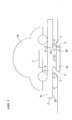
FIG. 2 is a rough diagram showing a structure of the main part of the first embodiment of the present invention. -
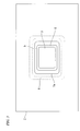
FIG. 3 is a top view showing a pallet, a power-supplying coil, a foreign matter removal section, a foreign matter receiving section, and a foreign matter adjacency prevention section of the first embodiment of the present invention. -
FIG. 4A is a schematic diagram showing the workings and effects of the first embodiment of the present invention. -
FIG. 4B is a schematic diagram showing the workings and effects of the first embodiment of the present invention. -
FIG. 4C is a schematic diagram showing the workings and effects of the first embodiment of the present invention. -
FIG. 4D is a schematic diagram showing the workings and effects of the first embodiment of the present invention. -
FIG. 5 is a rough diagram showing a structure of the main part of a second embodiment of the present invention. -
FIG. 6 is a top view showing a pallet, a power-supplying coil, a foreign matter removal section, a foreign matter receiving section, a foreign matter adjacency prevention section, a first foreign matter intrusion prevention wall, and a second foreign matter intrusion prevention wall of the second embodiment of the present invention. -
FIG. 7 is a diagram showing a first variant example of the present invention. - Hereunder is a description of embodiments of the present invention with reference to the drawings.
- A first embodiment will be described. As shown in
FIG. 1A, FIG. 1B , andFIG. 2 , a mechanical-parking place (parking facility) according to the first embodiment comprises avehicle storage rack 1;pallets 2; power-supplyingcoils 3; foreignmatter removal sections 4; foreignmatter receiving sections 5; and foreign matteradjacency prevention sections 6. - As shown in
FIG. 1A and 1B , thevehicle storage rack 1 is provided with a plurality of (27 in total) storage spaces S, three in each of the front-rear, left-right, and up-down directions. Thevehicle storage rack 1 shown in these figures limits the number of storage space S for convenience of explanation. However, thevehicle storage rack 1 may be provided with more number of or less number of storage spaces S. InFIGS. 1A, 1B , the storage spaces S are rectangular areas that are arranged in threes in each of the front-rear, left-right, and up-down directions.Pallets 2 are stored in some of the storage spaces. - The
pallet 2 is a rectangular plate member made of metal for mounting a vehicle M, and is formed so as to have a size slightly smaller than that of the storage space S. Based on the driving power from a drive mechanism (not shown in the figures) controlled by a control device (not shown in the figures), thepallet 2 moves in front-rear and left-right horizontal directions and in vertical direction. In a central or nearly central portion of thepallet 2, an opening 2a is formed. As for the position and size of the opening 2a, the position corresponds with that of a power-supplyingcoil 3 opposed to the opening 2a, and the size is slightly larger than that of the power-supplyingcoil 3, as shown inFIG. 2 . - The opening 2a is provided in the
pallet 2 in the intention of not obstructing a magnetic field emitted from the power-supplyingcoil 3. Namely, the portion of thepallet 2 that corresponds with the power-supplyingcoil 3 has magnetic field transmissibility. The opening 2a may be filled with a material with magnetic field transmissibility such as a resin that does not obstruct the magnetic field, with a view to reinforcing the mechanical strength of thepallet 2. - The power-supplying
coil 3 is a helical coil with a predetermined coil diameter. The power-supplyingcoil 3 is in an exposed state or in a molded state by a non-magnetic material such as a plastic, and is installed in a posture with a coil axis being in an up-down direction (vertical direction) on a floor surface s1 of the storage space S so as to be opposed to theopening 2a of thepallet 2. The power-supplyingcoil 3 has both of its ends connected to output terminals of a power-supplying circuit (not shown in the figures). With high frequency power being supplied from the power-supplying circuit, the power-supplyingcoil 3 generates a magnetic field, to thereby supply power wirelessly to the vehicle M. The power-supplying circuit is a type of inverter that is provided with a resonant capacitor for forming a power-supplying-side resonance circuit together with the power-supplyingcoil 3, and that converts input DC power to AC power (high frequency power) and supplies the AC power to the power-supplyingcoil 3. - Here, as is shown in the figure, the vehicle M is mounted on the
pallet 2. The vehicle M as a power supply target of the present mechanical-parking place is a hybrid vehicle driven by an engine and a motor, or an electric vehicle driven by a motor, namely, a vehicle that charges a rechargeable battery with power wirelessly received by the power-receiving coil J from the power-supplyingcoil 3 and that utilizes the power charged in the rechargeable battery as a power source of a motor for traveling. A conventional vehicle R driven only by an engine without being provided with the power-receiving coil J, the power-receiving circuit, the rechargeable battery, and the like is not the target of the present mechanical-parking place. - The power-receiving coil J is a helical coil with a predetermined coil diameter, and is provided in a bottom section of the vehicle M so that its coil axis is in the vertical direction. The power-receiving coil J has a coil diameter substantially the same as that of the power-supplying
coil 3. The power-receiving coil J has both of its ends connected to input terminals of a power-receiving circuit (not shown in the figures). When coupled electromagnetically with the power-supplyingcoil 3, the power-receiving coil J wirelessly receives AC power. The above-mentioned power-receiving circuit is a type of rectifier circuit that is provided with a resonant capacitor for forming a power-receiving-side resonance circuit together with the power-receiving coil J and that converts AC power supplied from the power-receiving coil J to DC power and supplies the DC power to the rechargeable battery. Note that capacitance of the resonant capacitor of the power-receiving circuit is set so that the resonance frequency of the power-supplying-side resonance circuit and the resonance frequency of the power-receiving-side resonance circuit be the same. - The foreign
matter removal section 4 is a brush that is made of a plurality of hair-like members formed of a flexible member (plastic, rubber, or the like) and that is adjusted to be long enough to contact with anupper surface 3a of the power-supplyingcoil 3. The foreignmatter removal section 4 is provided on alower surface 2b of thepallet 2 so as to surround theopening 2a (seeFIG. 3 ). With the horizontal movement of thepallet 2 in the front-rear and left-right directions, the foreignmatter removal section 4 horizontally moves along theupper surface 3a of the power-supplyingcoil 3. As a result, the foreignmatter removal section 4 slides along theupper surface 3a of the power-supplyingcoil 3, to thereby be capable of removing foreign matter such as litter present on theupper surface 3a of the power-supplyingcoil 3. InFIG. 3 , the positional relationship of theopening 2a and the foreignmatter removal section 4 with the power-supplyingcoil 3, the foreign matteradjacency prevention section 6, and the foreignmatter receiving section 5 is simplified for convenience of viewability. In actuality, the positional relationship is as shown inFIG. 2 . - As shown in
FIG. 3 , the foreignmatter receiving section 5 is provided lower than theupper surface 3a of the power-supplyingcoil 3 on the floor surface s1 of the storage space S and around the power-supplyingcoil 3. When the foreignmatter removal section 4 slides on theupper surface 3a of the power-supplyingcoil 3, the foreignmatter receiving section 5 receives the foreign matter removed from the surface of the power-supplyingcoil 3. - The foreign matter
adjacency prevention section 6 is made of a material through which a magnetic field is able to propagate without loss (plastic, rubber, or the like). The foreign matteradjacency prevention section 6 is provided between the foreignmatter receiving section 5 and the power-supplyingcoil 3 so as to have a given thickness and be in tight contact with aside surface 3b of the power-supplyingcoil 3 and so as to be at the same height as theupper surface 3a of the power-supplyingcoil 3. The foreign matteradjacency prevention section 6 prevents the foreign matter, which has been removed from theupper surface 3a of the power-supplyingcoil 3 by the foreignmatter removal section 4, from falling down immediately beside the power-supplyingcoil 3 and influencing the electromagnetic field. Namely, the foreign matteradjacency prevention section 6 prevents the foreign matter removed from theupper surface 3a of the power-supplyingcoil 3 from being adjacent to theside surface 3b of the power-supplyingcoil 3. - Subsequently, workings and effects of the mechanical-parking place with the structure explained above will be described in detail with reference to
FIG. 4A, FIG. 4B, FIG. 4C, and FIG. 4D . - When the vehicle M is to be parked in the present mechanical-parking place, the vehicle M is placed, for example by driving of a driver, on a
pallet 2 in a storage space S that is specified in advance as a storage entrance (for example, the storage space S located at the lowermost left position inFIG. 1B ). An operator operates on a storage instruction button of an operating device (not shown in the figures) of the mechanical-parking place, to thereby input a storage instruction to the control device. If, in this storage process, the operator receives a request to charge the rechargeable battery of the vehicle M, the operator operates on a charge instruction button in addition to the storage instruction button, to thereby input a charge instruction to the control device. - When the storage instruction and the charge instruction are input from the operating device, the control device of the mechanical-parking place moves the vehicle M in the storage entrance together with the
pallet 2 to an unoccupied storage space S. With a horizontal movement of thepallet 2 in the front-rear and left-right directions, the foreignmatter removal section 4 moves horizontally while sliding on theupper surface 3a of the power-supplyingcoil 3. - For example, suppose that before the
upper surface 3a of the power-supplyingcoil 3 is slid by the foreignmatter removal section 4, foreign matter is present on theupper surface 3a of the power-supplyingcoil 3, as shown inFIG. 4A . When the sliding movement of the foreignmatter removal section 4 on theupper surface 3a of the power-supplyingcoil 3 is started, the foreignmatter removal section 4 moves the foreign matter on theupper surface 3a of the power-supplyingcoil 3 toward the foreignmatter receiving section 5, as shown inFIG. 4B . With the sliding movement of the foreignmatter removal section 4, the foreign matter on theupper surface 3a of the power-supplyingcoil 3 falls down into the foreignmatter receiving section 5, as shown inFIG. 4C . After that, thepallet 2 stops at a position where theopening 2a is opposed to the power-supplyingcoil 3, as shown inFIG. 4D . Thus, the foreignmatter removal section 4 slides along theupper surface 3a of the power-supplyingcoil 3, to thereby be capable of removing the foreign matter present on theupper surface 3a of the power-supplyingcoil 3. - After completion of the movement of the vehicle M to the storage space S, the control device of the mechanical-parking place causes the power-supplying circuit to start to supply AC power to the power-supplying
coil 3. On the other hand, the vehicle M controls the power-receiving circuit while monitoring the state of charge of the rechargeable battery, to thereby properly charge the rechargeable battery. When the rechargeable battery is in the fully-charged state as a result of this charging operation, the vehicle M outputs a charge completion signal for notifying this fact by means of a communication unit (not shown in the figures). On the other hand, on receiving the charge completion signal, the control device of the mechanical-parking place causes the power-supplying circuit to stop the power supply to the power-supplyingcoil 3. - According to the first embodiment, it is possible to remove foreign matter present on the upper surface of the power-supplying
coil 3 by the foreignmatter removal section 4 that, with the movement of thepallet 2, is brought into contact with theupper surface 3a of the power-supplyingcoil 3 to engage (for example, to push) the foreign matter on theupper surface 3a of the power-supplyingcoil 3, to thereby remove the foreign matter from theupper surface 3a of the power-supplyingcoil 3. Furthermore, in the first embodiment, the already-existingpallets 2 are utilized to remove foreign matter. This eliminates the necessity of mounting new movable units. Therefore, it is possible to reduce an increase in manufacturing costs. - A mechanical-parking place according to a second embodiment will be described.
- As shown in
FIG. 5 andFIG. 6 , the mechanical-parking place according to the second embodiment is provided with a first foreign matterintrusion prevention wall 7 and a second foreign matterintrusion prevention wall 8 in addition to the first embodiment. The constituent elements other than these are the same as those of the first embodiment. Therefore, explanations of constituent elements of the second embodiment same as those of the first embodiment are omitted. InFIG. 6 , a positional relationship of theopening 2a, the second foreign matterintrusion prevention wall 8, and the foreignmatter removal section 4 with the power-supplyingcoil 3, the foreign matteradjacency prevention section 6, the foreignmatter receiving section 5, and the first foreign matterintrusion prevention wall 7 is simplified for convenience of viewability. In actuality, the positional relationship is as shown inFIG 5 . - The first foreign matter
intrusion prevention wall 7 is provided on the floor surface s1 of the storage space S so as to surround the power-supplyingcoil 3 and so as to be high enough to contact a lower end of the foreignmatter removal section 4. By surrounding the power-supplyingcoil 3 together with the foreignmatter removal section 4, the first foreign matterintrusion prevention wall 7 prevents foreign matter from intruding into a space between the power-supplyingcoil 3 and the power-receiving coil J from below thepallet 2. - The second foreign matter
intrusion prevention wall 8 is provided on anupper surface 2c of thepallet 2 so as to surround theopening 2a of thepallet 2 and so as to be lower than a bottom surface of the vehicle. By surrounding theopening 2a on theupper surface 2c of thepallet 2, the second foreign matterintrusion prevention wall 8 prevents foreign matter from intruding into the space between power-supplyingcoil 3 and the power-receiving coil J through a gap between the bottom section of the vehicle M and thepallet 2. - Subsequently, the workings and effects of the second embodiment with the structure explained above will be described in detail. Note that an explanation of the workings same as those of the first embodiment will not be repeated.
- In the mechanical-parking place, with the horizontal movement of the
pallet 2 in the front-rear and left-right directions, the foreignmatter removal section 4 horizontally moves on theupper surface 3a of the power-supplyingcoil 3 in a sliding manner. As a result, the foreignmatter removal section 4 slides along theupper surface 3a of the power-supplyingcoil 3, to thereby be capable of removing foreign matter present on theupper surface 3a of the power-supplyingcoil 3. - After completion of the movement of the vehicle M to the storage space S, the control device of the mechanical-parking place causes the power-supplying circuit to start to supply AC power to the power-supplying
coil 3. On the other hand, the vehicle M controls the power-receiving circuit while monitoring the state of charge of the rechargeable battery, to thereby properly charge the rechargeable battery. Here, the first foreign matterintrusion prevention wall 7 is in contact with the lower end of the foreignmatter removal section 4 and surrounds the power-supplyingcoil 3 together with the foreignmatter removal section 4, to thereby prevent foreign matter from intruding into the space between the power-supplyingcoil 3 and the power-receiving coil J from below thepallet 2. Furthermore, on theupper surface 2c of thepallet 2, the second foreign matterintrusion prevention wall 8 surrounds theopening 2a, to thereby prevent foreign matter from intruding into the space between the power-supplyingcoil 3 and the power-receiving coil J through the gap between the bottom section of the vehicle M and thepallet 2. - According to the second embodiment, in addition to the effects of the first embodiment, it is possible to prevent the intrusion of foreign matter by means of the first foreign matter
intrusion prevention wall 7 and the second foreign matterintrusion prevention wall 8. - The present invention is not limited to the above-mentioned embodiments, and for example the following variant examples are conceivable:
- (1) In the first embodiment, the foreign
matter removal section 4 is provided so as to surround theopening 2a. However, the present invention is not limited to this. For example, in the case where the horizontal movement of thepallet 2 is only in the front-rear direction, a foreignmatter removal section 14 may be provided on both of the near side and the far side of theopening 2a in the moving direction of thepallet 2, as shown inFIG. 7 (which shows the first embodiment, by way of example). Namely, in accordance with the direction of the horizontal movement of thepallet 2, the foreignmatter removal sections 14 may be provided at the minimum required positions that allow the foreignmatter removal sections 14 to slide on theupper surface 3a of the power-supplyingcoil 3. - (2) In the first and second embodiments, the foreign
matter removal section 4 is adjusted to be long enough to contact theupper surface 3a of the power-supplyingcoil 3. However, the foreignmatter removal section 4 may be spaced a given distance from theupper surface 3a of the power-supplyingcoil 3. Namely, being spaced a given distance from theupper surface 3a of the power-supplyingcoil 3, the foreignmatter removal section 4 may engage foreign matter present on theupper surface 3a of the power-supplyingcoil 3 and remove the foreign matter from theupper surface 3a of the power-supplyingcoil 3. For example, if minute foreign matter that does not affect the wireless power supply is allowed to remain on theupper surface 3a of the power-supplyingcoil 3, then the foreignmatter removal section 4 may be spaced from theupper surface 3a of the power-supplyingcoil 3 by L or less where L is a minimum size of the foreign matter to be removed. - (3) For the foreign
matter removal section 4, a blade member may be used instead of a brush. - (4) In the above-mentioned embodiments, the power-supplying
coil 3 is provided in all the storage spaces S that constitute thevehicle storage rack 1, to thereby make the power supply available in all of the storage spaces S. However, the present invention is not limited to this. The power-supplyingcoil 3 may be provided in some of the storage spaces S, and the vehicle M which the driver requests to be charged with power may be selectively moved from the storage entrance to the storage space S provided with the power-supplyingcoil 3. - (5) In the above-mentioned embodiments, the
opening 2a is provided in thepallet 2 made of metal in order to enhance the power-supplying efficiency. However, the present invention is not limited to this. For example, the pallet may be formed from a resin material with high rigidity, namely, a material with rigidity and low magnetic permeability. This makes it possible to enhance the power-supplying efficiency without providing an opening. - (6) In the above-mentioned embodiments, a magnetic field resonance system is adopted as a method of carrying out wireless power supply. However, an electromagnetic induction system may be adopted.
- (7) The power-supplying
coil 3 and the power-receiving coil J are not limited to helical coils. So long as wireless power supply is available between the power-supplyingcoil 3 and the power-receiving coil J, the coils may have arbitrary type and shape such as a solenoid shape. In addition, the coils may be different in type, shape, and size. - It is possible to remove foreign matter present on the power-supplying coil and also to reduce an increase in manufacturing costs due to the movable unit.
-
- 1:
- vehicle storage rack
- 2:
- pallet
- 3:
- power-supplying coil
- 4, 14:
- foreign matter removal section
- 5:
- foreign matter receiving section
- 6:
- foreign matter adjacency prevention section
- 2a:
- opening
- 2b:
- lower surface
- 2c:
- upper surface
- 3a:
- upper surface
- 3b:
- side surface
- M:
- vehicle
- J:
- power-receiving coil
- s1:
- floor surface
Claims (10)
- A parking facility that horizontally moves a pallet on which a vehicle is mounted, to thereby store the vehicle in a storage space, comprising:the pallet having magnetic field transmissibility in a portion corresponding with a power-receiving coil provided on a bottom surface of the vehicle;a power-supplying coil that is provided in the storage space so as to be opposed to the portion with the magnetic field transmissibility and that supplies power wirelessly to the power-receiving coil; anda foreign matter removal section that is provided on a lower surface of the pallet and that, with a movement of the pallet, engages, by contacting an upper surface of the power-supplying coil or by being spaced a given distance from the upper surface of the power-supplying coil, foreign matter present on the upper surface of the power-supplying coil, to thereby remove the foreign matter from the upper surface of the power-supplying coil.
- The parking facility according to claim 1, comprising
a foreign matter receiving section that is provided around the power-supplying coil and is lower than the upper surface of the power-supplying coil. - The parking facility according to claim 2, comprising
a foreign matter adjacency prevention section with magnetic field transmissibility that is provided between the foreign matter receiving section and the power-supplying coil so as to be in tight contact with a side surface of the power-supplying coil and so as to be at a level equal to that of the upper surface of the power-supplying coil. - The parking facility according to claim 1, comprising
a foreign matter intrusion prevention wall that is provided around the power-supplying coil so as to be at a position opposed to the foreign matter removal section and so as to be high enough to contact a lower end of the foreign matter removal section. - The parking facility according to claim 1, comprising
a second foreign matter intrusion prevention wall that is provided on an upper surface of the pallet and is lower than the bottom surface of the vehicle. - The parking facility according to claim 2, comprising
a foreign matter intrusion prevention wall that is provided around the power-supplying coil so as to be at a position opposed to the foreign matter removal section and so as to be high enough to contact a lower end of the foreign matter removal section. - The parking facility according to claim 3, comprising
a foreign matter intrusion prevention wall that is provided around the power-supplying coil so as to be at a position opposed to the foreign matter removal section and so as to be high enough to contact a lower end of the foreign matter removal section. - The parking facility according to claim 2, comprising
a second foreign matter intrusion prevention wall that is provided on an upper surface of the pallet and is lower than the bottom surface of the vehicle. - The parking facility according to claim 3, comprising
a second foreign matter intrusion prevention wall that is provided on an upper surface of the pallet and is lower than the bottom surface of the vehicle. - The parking facility according to claim 4, comprising
a second foreign matter intrusion prevention wall that is provided on an upper surface of the pallet and is lower than the bottom surface of the vehicle.
Applications Claiming Priority (2)
| Application Number | Priority Date | Filing Date | Title |
|---|---|---|---|
| JP2012180551A JP5998737B2 (en) | 2012-08-16 | 2012-08-16 | Mobile parking facilities |
| PCT/JP2013/066600 WO2014027506A1 (en) | 2012-08-16 | 2013-06-17 | Moving parking facility |
Publications (3)
| Publication Number | Publication Date |
|---|---|
| EP2887498A1 true EP2887498A1 (en) | 2015-06-24 |
| EP2887498A4 EP2887498A4 (en) | 2016-07-06 |
| EP2887498B1 EP2887498B1 (en) | 2018-09-05 |
Family
ID=50287107
Family Applications (1)
| Application Number | Title | Priority Date | Filing Date |
|---|---|---|---|
| EP13879345.0A Active EP2887498B1 (en) | 2012-08-16 | 2013-06-17 | Moving parking facility |
Country Status (5)
| Country | Link |
|---|---|
| US (1) | US9662993B2 (en) |
| EP (1) | EP2887498B1 (en) |
| JP (1) | JP5998737B2 (en) |
| CN (1) | CN104521104B (en) |
| WO (1) | WO2014027506A1 (en) |
Families Citing this family (24)
| Publication number | Priority date | Publication date | Assignee | Title |
|---|---|---|---|---|
| GB201403548D0 (en) * | 2014-02-28 | 2014-04-16 | Bombardier Transp Gmbh | Inductive power transfer pad comprising a stationary part and a moveable part |
| JP2015186311A (en) * | 2014-03-21 | 2015-10-22 | Ihi運搬機械株式会社 | non-contact power supply system |
| FR3019204B1 (en) * | 2014-03-28 | 2017-11-17 | Soletanche Freyssinet | UNDERGROUND PARKING FOR ELECTRIC VEHICLES |
| GB2525239A (en) * | 2014-04-17 | 2015-10-21 | Bombardier Transp Gmbh | Object detection system and method for detecting foreign objects in an inductive power transfer system |
| JP6375703B2 (en) * | 2014-06-06 | 2018-08-22 | 株式会社Ihi | Power transmission device and non-contact power feeding system |
| JP6308047B2 (en) * | 2014-06-24 | 2018-04-11 | 株式会社Ihi | Contactless power supply system, power transmission device, power reception device |
| EP3160007B1 (en) | 2014-06-06 | 2018-12-26 | IHI Corporation | Power transmitting device, power receiving device, and wireless power supply system |
| US9522604B2 (en) * | 2014-08-04 | 2016-12-20 | Ford Global Technologies, Llc | Inductive wireless power transfer system having a coupler assembly comprising moveable permeable panels |
| CN106828130B (en) * | 2015-12-07 | 2020-10-30 | 兰溪市迅捷电气有限公司 | Buried charging device and charging method |
| CN107294149B (en) * | 2016-03-31 | 2020-08-25 | 比亚迪股份有限公司 | Wireless charging system, power supply device and foreign matter monitoring method and system |
| JP6956474B2 (en) * | 2016-08-29 | 2021-11-02 | 日本無線株式会社 | Power transmission relay device |
| JP6868984B2 (en) * | 2016-08-29 | 2021-05-12 | 日本無線株式会社 | Foreign matter intervention prevention device |
| CN106368470B (en) * | 2016-08-30 | 2019-02-01 | 四川科莱立泊停车设备有限公司 | A kind of vertical elevating garage rotary frame pulley support body mechanism |
| CN115765220A (en) | 2017-02-09 | 2023-03-07 | 松下知识产权经营株式会社 | Control method for power transmission device and power transmission device |
| JP6551755B2 (en) | 2017-02-09 | 2019-07-31 | パナソニックIpマネジメント株式会社 | Control method of power transmission device in wireless power transmission system, and power transmission device |
| CN107591903A (en) * | 2017-09-05 | 2018-01-16 | 中惠创智无线供电技术有限公司 | Foreign matter for electric power wireless transmitting system removes equipment and its application method |
| DE102018008252A1 (en) * | 2017-11-03 | 2019-05-09 | Sew-Eurodrive Gmbh & Co Kg | System for the contactless transmission of electrical energy to a handset |
| WO2020026868A1 (en) * | 2018-07-31 | 2020-02-06 | パナソニックIpマネジメント株式会社 | Power transmission device, power reception device, wireless power transmission system, and method for driving power transmission device |
| CN109098508A (en) * | 2018-08-22 | 2018-12-28 | 安徽信息工程学院 | Cross sliding type modularized parking device |
| CN110027426A (en) * | 2019-04-17 | 2019-07-19 | 合芯磁导科技(无锡)有限公司 | A kind of cleaning structure of intelligent radio charging transmitter |
| JP7424765B2 (en) * | 2019-07-02 | 2024-01-30 | 東芝テック株式会社 | Power receiving system |
| JP2021072750A (en) * | 2019-11-01 | 2021-05-06 | 東芝テック株式会社 | Power transmission device and power transmission/reception system |
| CN114802128A (en) * | 2021-01-29 | 2022-07-29 | 鸿富锦精密工业(深圳)有限公司 | Vehicle parking auxiliary system and parking method |
| CN113335089A (en) * | 2021-06-26 | 2021-09-03 | 深圳欣锐科技股份有限公司 | Electric energy receiving platform, charging system and vehicle |
Family Cites Families (18)
| Publication number | Priority date | Publication date | Assignee | Title |
|---|---|---|---|---|
| JP4146098B2 (en) * | 2001-02-07 | 2008-09-03 | 新明和工業株式会社 | Multistage parking facilities |
| JP4442517B2 (en) * | 2005-06-07 | 2010-03-31 | パナソニック電工株式会社 | Non-contact power supply device and power supply system for autonomous mobile device |
| CN101057765A (en) * | 2007-04-28 | 2007-10-24 | 金日清洁设备(苏州)有限公司 | Ground cleaning machine |
| JP2010022183A (en) * | 2008-02-08 | 2010-01-28 | Suri-Ai:Kk | Electric vehicle and inductive power-transmission device suitable therefor |
| JP5606098B2 (en) * | 2009-02-25 | 2014-10-15 | マスプロ電工株式会社 | Mobile power supply system |
| JP5480573B2 (en) * | 2009-09-25 | 2014-04-23 | パナソニック株式会社 | Contactless charging system |
| JP5688888B2 (en) * | 2009-10-07 | 2015-03-25 | 日精株式会社 | Mechanical parking equipment |
| JP5559518B2 (en) * | 2009-10-30 | 2014-07-23 | 富士変速機株式会社 | Three-dimensional parking device and non-contact charging device for electric vehicle |
| JP2011120345A (en) * | 2009-12-02 | 2011-06-16 | Jfe Engineering Corp | Protective mechanism for electric vehicle charger |
| DE102009047504A1 (en) * | 2009-12-04 | 2011-06-09 | WAP Wöhr Automatikparksysteme GmbH & Co KG | Method for operating a park and park |
| DE102010020122B4 (en) * | 2010-05-10 | 2021-07-15 | Sew-Eurodrive Gmbh & Co Kg | Arrangement for contactless energy transfer |
| JP5593147B2 (en) * | 2010-07-13 | 2014-09-17 | 株式会社岡村製作所 | Furniture system |
| JP5720367B2 (en) | 2011-03-30 | 2015-05-20 | 株式会社Ihi | Parking facilities |
| JP2013021886A (en) * | 2011-07-14 | 2013-01-31 | Sony Corp | Power supply apparatus, power supply system, vehicle, and electronic apparatus |
| JP5906691B2 (en) | 2011-11-28 | 2016-04-20 | 株式会社Ihi | Non-contact power transmission device and mobile vehicle |
| JP6060546B2 (en) | 2012-07-26 | 2017-01-18 | 株式会社Ihi | Contactless power supply system |
| JP6111583B2 (en) | 2012-10-01 | 2017-04-12 | 株式会社Ihi | Contactless power supply system |
| WO2014200024A1 (en) * | 2013-06-13 | 2014-12-18 | 矢崎総業株式会社 | Power feeding device and power feeding system |
-
2012
- 2012-08-16 JP JP2012180551A patent/JP5998737B2/en active Active
-
2013
- 2013-06-17 CN CN201380041728.2A patent/CN104521104B/en active Active
- 2013-06-17 WO PCT/JP2013/066600 patent/WO2014027506A1/en not_active Ceased
- 2013-06-17 EP EP13879345.0A patent/EP2887498B1/en active Active
-
2015
- 2015-01-12 US US14/594,628 patent/US9662993B2/en active Active
Also Published As
| Publication number | Publication date |
|---|---|
| US20150123609A1 (en) | 2015-05-07 |
| WO2014027506A1 (en) | 2014-02-20 |
| EP2887498A4 (en) | 2016-07-06 |
| CN104521104B (en) | 2017-10-24 |
| CN104521104A (en) | 2015-04-15 |
| US9662993B2 (en) | 2017-05-30 |
| EP2887498B1 (en) | 2018-09-05 |
| JP2014039403A (en) | 2014-02-27 |
| JP5998737B2 (en) | 2016-09-28 |
Similar Documents
| Publication | Publication Date | Title |
|---|---|---|
| EP2887498B1 (en) | Moving parking facility | |
| EP2692966B1 (en) | Parking facility | |
| JP6024106B2 (en) | Transfer device and mobile vehicle | |
| US10476314B2 (en) | Wireless power-supplying system | |
| JP6427873B2 (en) | Parking assistance device and system | |
| EP2905399B1 (en) | Automated parking facility | |
| US9248475B2 (en) | Foreign matter removal mechanism | |
| US20180126858A1 (en) | Energy Supply Vehicle for Supplying an Electrically Drivable Motor Vehicle with Electrical Energy | |
| EP2757657A1 (en) | Moving-vehicle electric power feeding system | |
| JP5367425B2 (en) | Mechanical parking lot | |
| KR20120051013A (en) | Power supply unit, land vehicle, exchange method and exchange office of power supply unit included in the land vehicle | |
| EP2919364B1 (en) | Contactless electric power supply system | |
| US9994255B2 (en) | Vehicle guidance apparatus and vehicle guidance method | |
| CN102264988A (en) | Vehicle parking device | |
| JP7694859B2 (en) | Battery exchange control system and method | |
| JP2014054128A (en) | Vehicle power supply device | |
| JP2014054133A (en) | Vehicle power supply device | |
| JP2011099260A (en) | Multistory parking system, control unit, and control method | |
| WO2015147093A1 (en) | Non-contact power supply system and vehicle power supply device | |
| JP7511337B2 (en) | Mechanical parking lot | |
| CN102041913B (en) | Mechanical parking device | |
| JP2022144402A (en) | Mechanical parking device and charging method for electric vehicle | |
| JP6172917B2 (en) | Parking device, vehicle feeding system and vehicle | |
| TWI451016B (en) | Mechanical parking | |
| JP2015165090A (en) | Parking facilities |
Legal Events
| Date | Code | Title | Description |
|---|---|---|---|
| PUAI | Public reference made under article 153(3) epc to a published international application that has entered the european phase |
Free format text: ORIGINAL CODE: 0009012 |
|
| 17P | Request for examination filed |
Effective date: 20150114 |
|
| AK | Designated contracting states |
Kind code of ref document: A1 Designated state(s): AL AT BE BG CH CY CZ DE DK EE ES FI FR GB GR HR HU IE IS IT LI LT LU LV MC MK MT NL NO PL PT RO RS SE SI SK SM TR |
|
| AX | Request for extension of the european patent |
Extension state: BA ME |
|
| DAX | Request for extension of the european patent (deleted) | ||
| REG | Reference to a national code |
Ref country code: DE Ref legal event code: R079 Ref document number: 602013043380 Country of ref document: DE Free format text: PREVIOUS MAIN CLASS: H02J0017000000 Ipc: B60M0007000000 |
|
| RA4 | Supplementary search report drawn up and despatched (corrected) |
Effective date: 20160606 |
|
| RIC1 | Information provided on ipc code assigned before grant |
Ipc: B60L 11/18 20060101ALI20160531BHEP Ipc: E04H 6/42 20060101ALI20160531BHEP Ipc: H02J 7/00 20060101ALI20160531BHEP Ipc: B60M 7/00 20060101AFI20160531BHEP |
|
| GRAP | Despatch of communication of intention to grant a patent |
Free format text: ORIGINAL CODE: EPIDOSNIGR1 |
|
| STAA | Information on the status of an ep patent application or granted ep patent |
Free format text: STATUS: GRANT OF PATENT IS INTENDED |
|
| INTG | Intention to grant announced |
Effective date: 20180518 |
|
| RIN1 | Information on inventor provided before grant (corrected) |
Inventor name: NIIZUMA, MOTONAO |
|
| GRAS | Grant fee paid |
Free format text: ORIGINAL CODE: EPIDOSNIGR3 |
|
| GRAA | (expected) grant |
Free format text: ORIGINAL CODE: 0009210 |
|
| STAA | Information on the status of an ep patent application or granted ep patent |
Free format text: STATUS: THE PATENT HAS BEEN GRANTED |
|
| AK | Designated contracting states |
Kind code of ref document: B1 Designated state(s): AL AT BE BG CH CY CZ DE DK EE ES FI FR GB GR HR HU IE IS IT LI LT LU LV MC MK MT NL NO PL PT RO RS SE SI SK SM TR |
|
| REG | Reference to a national code |
Ref country code: GB Ref legal event code: FG4D |
|
| REG | Reference to a national code |
Ref country code: CH Ref legal event code: EP |
|
| REG | Reference to a national code |
Ref country code: AT Ref legal event code: REF Ref document number: 1037405 Country of ref document: AT Kind code of ref document: T Effective date: 20180915 |
|
| REG | Reference to a national code |
Ref country code: IE Ref legal event code: FG4D |
|
| REG | Reference to a national code |
Ref country code: DE Ref legal event code: R096 Ref document number: 602013043380 Country of ref document: DE |
|
| REG | Reference to a national code |
Ref country code: NL Ref legal event code: MP Effective date: 20180905 |
|
| REG | Reference to a national code |
Ref country code: LT Ref legal event code: MG4D |
|
| PG25 | Lapsed in a contracting state [announced via postgrant information from national office to epo] |
Ref country code: RS Free format text: LAPSE BECAUSE OF FAILURE TO SUBMIT A TRANSLATION OF THE DESCRIPTION OR TO PAY THE FEE WITHIN THE PRESCRIBED TIME-LIMIT Effective date: 20180905 Ref country code: FI Free format text: LAPSE BECAUSE OF FAILURE TO SUBMIT A TRANSLATION OF THE DESCRIPTION OR TO PAY THE FEE WITHIN THE PRESCRIBED TIME-LIMIT Effective date: 20180905 Ref country code: GR Free format text: LAPSE BECAUSE OF FAILURE TO SUBMIT A TRANSLATION OF THE DESCRIPTION OR TO PAY THE FEE WITHIN THE PRESCRIBED TIME-LIMIT Effective date: 20181206 Ref country code: NO Free format text: LAPSE BECAUSE OF FAILURE TO SUBMIT A TRANSLATION OF THE DESCRIPTION OR TO PAY THE FEE WITHIN THE PRESCRIBED TIME-LIMIT Effective date: 20181205 Ref country code: SE Free format text: LAPSE BECAUSE OF FAILURE TO SUBMIT A TRANSLATION OF THE DESCRIPTION OR TO PAY THE FEE WITHIN THE PRESCRIBED TIME-LIMIT Effective date: 20180905 Ref country code: LT Free format text: LAPSE BECAUSE OF FAILURE TO SUBMIT A TRANSLATION OF THE DESCRIPTION OR TO PAY THE FEE WITHIN THE PRESCRIBED TIME-LIMIT Effective date: 20180905 Ref country code: BG Free format text: LAPSE BECAUSE OF FAILURE TO SUBMIT A TRANSLATION OF THE DESCRIPTION OR TO PAY THE FEE WITHIN THE PRESCRIBED TIME-LIMIT Effective date: 20181205 |
|
| REG | Reference to a national code |
Ref country code: AT Ref legal event code: MK05 Ref document number: 1037405 Country of ref document: AT Kind code of ref document: T Effective date: 20180905 |
|
| PG25 | Lapsed in a contracting state [announced via postgrant information from national office to epo] |
Ref country code: HR Free format text: LAPSE BECAUSE OF FAILURE TO SUBMIT A TRANSLATION OF THE DESCRIPTION OR TO PAY THE FEE WITHIN THE PRESCRIBED TIME-LIMIT Effective date: 20180905 Ref country code: LV Free format text: LAPSE BECAUSE OF FAILURE TO SUBMIT A TRANSLATION OF THE DESCRIPTION OR TO PAY THE FEE WITHIN THE PRESCRIBED TIME-LIMIT Effective date: 20180905 Ref country code: AL Free format text: LAPSE BECAUSE OF FAILURE TO SUBMIT A TRANSLATION OF THE DESCRIPTION OR TO PAY THE FEE WITHIN THE PRESCRIBED TIME-LIMIT Effective date: 20180905 |
|
| PG25 | Lapsed in a contracting state [announced via postgrant information from national office to epo] |
Ref country code: NL Free format text: LAPSE BECAUSE OF FAILURE TO SUBMIT A TRANSLATION OF THE DESCRIPTION OR TO PAY THE FEE WITHIN THE PRESCRIBED TIME-LIMIT Effective date: 20180905 Ref country code: CZ Free format text: LAPSE BECAUSE OF FAILURE TO SUBMIT A TRANSLATION OF THE DESCRIPTION OR TO PAY THE FEE WITHIN THE PRESCRIBED TIME-LIMIT Effective date: 20180905 Ref country code: IS Free format text: LAPSE BECAUSE OF FAILURE TO SUBMIT A TRANSLATION OF THE DESCRIPTION OR TO PAY THE FEE WITHIN THE PRESCRIBED TIME-LIMIT Effective date: 20190105 Ref country code: RO Free format text: LAPSE BECAUSE OF FAILURE TO SUBMIT A TRANSLATION OF THE DESCRIPTION OR TO PAY THE FEE WITHIN THE PRESCRIBED TIME-LIMIT Effective date: 20180905 Ref country code: PL Free format text: LAPSE BECAUSE OF FAILURE TO SUBMIT A TRANSLATION OF THE DESCRIPTION OR TO PAY THE FEE WITHIN THE PRESCRIBED TIME-LIMIT Effective date: 20180905 Ref country code: EE Free format text: LAPSE BECAUSE OF FAILURE TO SUBMIT A TRANSLATION OF THE DESCRIPTION OR TO PAY THE FEE WITHIN THE PRESCRIBED TIME-LIMIT Effective date: 20180905 Ref country code: AT Free format text: LAPSE BECAUSE OF FAILURE TO SUBMIT A TRANSLATION OF THE DESCRIPTION OR TO PAY THE FEE WITHIN THE PRESCRIBED TIME-LIMIT Effective date: 20180905 Ref country code: IT Free format text: LAPSE BECAUSE OF FAILURE TO SUBMIT A TRANSLATION OF THE DESCRIPTION OR TO PAY THE FEE WITHIN THE PRESCRIBED TIME-LIMIT Effective date: 20180905 |
|
| PG25 | Lapsed in a contracting state [announced via postgrant information from national office to epo] |
Ref country code: SM Free format text: LAPSE BECAUSE OF FAILURE TO SUBMIT A TRANSLATION OF THE DESCRIPTION OR TO PAY THE FEE WITHIN THE PRESCRIBED TIME-LIMIT Effective date: 20180905 Ref country code: SK Free format text: LAPSE BECAUSE OF FAILURE TO SUBMIT A TRANSLATION OF THE DESCRIPTION OR TO PAY THE FEE WITHIN THE PRESCRIBED TIME-LIMIT Effective date: 20180905 Ref country code: PT Free format text: LAPSE BECAUSE OF FAILURE TO SUBMIT A TRANSLATION OF THE DESCRIPTION OR TO PAY THE FEE WITHIN THE PRESCRIBED TIME-LIMIT Effective date: 20190105 |
|
| REG | Reference to a national code |
Ref country code: DE Ref legal event code: R097 Ref document number: 602013043380 Country of ref document: DE |
|
| PLBE | No opposition filed within time limit |
Free format text: ORIGINAL CODE: 0009261 |
|
| STAA | Information on the status of an ep patent application or granted ep patent |
Free format text: STATUS: NO OPPOSITION FILED WITHIN TIME LIMIT |
|
| PG25 | Lapsed in a contracting state [announced via postgrant information from national office to epo] |
Ref country code: DK Free format text: LAPSE BECAUSE OF FAILURE TO SUBMIT A TRANSLATION OF THE DESCRIPTION OR TO PAY THE FEE WITHIN THE PRESCRIBED TIME-LIMIT Effective date: 20180905 Ref country code: ES Free format text: LAPSE BECAUSE OF FAILURE TO SUBMIT A TRANSLATION OF THE DESCRIPTION OR TO PAY THE FEE WITHIN THE PRESCRIBED TIME-LIMIT Effective date: 20180905 |
|
| 26N | No opposition filed |
Effective date: 20190606 |
|
| PG25 | Lapsed in a contracting state [announced via postgrant information from national office to epo] |
Ref country code: SI Free format text: LAPSE BECAUSE OF FAILURE TO SUBMIT A TRANSLATION OF THE DESCRIPTION OR TO PAY THE FEE WITHIN THE PRESCRIBED TIME-LIMIT Effective date: 20180905 |
|
| PG25 | Lapsed in a contracting state [announced via postgrant information from national office to epo] |
Ref country code: MC Free format text: LAPSE BECAUSE OF FAILURE TO SUBMIT A TRANSLATION OF THE DESCRIPTION OR TO PAY THE FEE WITHIN THE PRESCRIBED TIME-LIMIT Effective date: 20180905 |
|
| REG | Reference to a national code |
Ref country code: CH Ref legal event code: PL |
|
| GBPC | Gb: european patent ceased through non-payment of renewal fee |
Effective date: 20190617 |
|
| REG | Reference to a national code |
Ref country code: BE Ref legal event code: MM Effective date: 20190630 |
|
| PG25 | Lapsed in a contracting state [announced via postgrant information from national office to epo] |
Ref country code: TR Free format text: LAPSE BECAUSE OF FAILURE TO SUBMIT A TRANSLATION OF THE DESCRIPTION OR TO PAY THE FEE WITHIN THE PRESCRIBED TIME-LIMIT Effective date: 20180905 |
|
| PG25 | Lapsed in a contracting state [announced via postgrant information from national office to epo] |
Ref country code: GB Free format text: LAPSE BECAUSE OF NON-PAYMENT OF DUE FEES Effective date: 20190617 Ref country code: IE Free format text: LAPSE BECAUSE OF NON-PAYMENT OF DUE FEES Effective date: 20190617 |
|
| PG25 | Lapsed in a contracting state [announced via postgrant information from national office to epo] |
Ref country code: LI Free format text: LAPSE BECAUSE OF NON-PAYMENT OF DUE FEES Effective date: 20190630 Ref country code: LU Free format text: LAPSE BECAUSE OF NON-PAYMENT OF DUE FEES Effective date: 20190617 Ref country code: CH Free format text: LAPSE BECAUSE OF NON-PAYMENT OF DUE FEES Effective date: 20190630 Ref country code: BE Free format text: LAPSE BECAUSE OF NON-PAYMENT OF DUE FEES Effective date: 20190630 |
|
| PG25 | Lapsed in a contracting state [announced via postgrant information from national office to epo] |
Ref country code: FR Free format text: LAPSE BECAUSE OF NON-PAYMENT OF DUE FEES Effective date: 20190630 |
|
| PG25 | Lapsed in a contracting state [announced via postgrant information from national office to epo] |
Ref country code: CY Free format text: LAPSE BECAUSE OF FAILURE TO SUBMIT A TRANSLATION OF THE DESCRIPTION OR TO PAY THE FEE WITHIN THE PRESCRIBED TIME-LIMIT Effective date: 20180905 |
|
| PG25 | Lapsed in a contracting state [announced via postgrant information from national office to epo] |
Ref country code: MT Free format text: LAPSE BECAUSE OF FAILURE TO SUBMIT A TRANSLATION OF THE DESCRIPTION OR TO PAY THE FEE WITHIN THE PRESCRIBED TIME-LIMIT Effective date: 20180905 Ref country code: HU Free format text: LAPSE BECAUSE OF FAILURE TO SUBMIT A TRANSLATION OF THE DESCRIPTION OR TO PAY THE FEE WITHIN THE PRESCRIBED TIME-LIMIT; INVALID AB INITIO Effective date: 20130617 |
|
| PG25 | Lapsed in a contracting state [announced via postgrant information from national office to epo] |
Ref country code: MK Free format text: LAPSE BECAUSE OF FAILURE TO SUBMIT A TRANSLATION OF THE DESCRIPTION OR TO PAY THE FEE WITHIN THE PRESCRIBED TIME-LIMIT Effective date: 20180905 |
|
| PGFP | Annual fee paid to national office [announced via postgrant information from national office to epo] |
Ref country code: DE Payment date: 20250520 Year of fee payment: 13 |