EP2887484A1 - Converter module and switchgear assembly for AC and DC power distribution - Google Patents
Converter module and switchgear assembly for AC and DC power distribution Download PDFInfo
- Publication number
- EP2887484A1 EP2887484A1 EP13005972.8A EP13005972A EP2887484A1 EP 2887484 A1 EP2887484 A1 EP 2887484A1 EP 13005972 A EP13005972 A EP 13005972A EP 2887484 A1 EP2887484 A1 EP 2887484A1
- Authority
- EP
- European Patent Office
- Prior art keywords
- power
- converter
- power distribution
- modules
- bus bars
- Prior art date
- Legal status (The legal status is an assumption and is not a legal conclusion. Google has not performed a legal analysis and makes no representation as to the accuracy of the status listed.)
- Granted
Links
Images


Classifications
-
- H—ELECTRICITY
- H02—GENERATION; CONVERSION OR DISTRIBUTION OF ELECTRIC POWER
- H02M—APPARATUS FOR CONVERSION BETWEEN AC AND AC, BETWEEN AC AND DC, OR BETWEEN DC AND DC, AND FOR USE WITH MAINS OR SIMILAR POWER SUPPLY SYSTEMS; CONVERSION OF DC OR AC INPUT POWER INTO SURGE OUTPUT POWER; CONTROL OR REGULATION THEREOF
- H02M7/00—Conversion of AC power input into DC power output; Conversion of DC power input into AC power output
- H02M7/42—Conversion of DC power input into AC power output without possibility of reversal
- H02M7/44—Conversion of DC power input into AC power output without possibility of reversal by static converters
- H02M7/48—Conversion of DC power input into AC power output without possibility of reversal by static converters using discharge tubes with control electrode or semiconductor devices with control electrode
- H02M7/493—Conversion of DC power input into AC power output without possibility of reversal by static converters using discharge tubes with control electrode or semiconductor devices with control electrode the static converters being arranged for operation in parallel
-
- H—ELECTRICITY
- H02—GENERATION; CONVERSION OR DISTRIBUTION OF ELECTRIC POWER
- H02J—ELECTRIC POWER NETWORKS; CIRCUIT ARRANGEMENTS OR SYSTEMS FOR SUPPLYING OR DISTRIBUTING ELECTRIC POWER; SYSTEMS FOR STORING ELECTRIC ENERGY
- H02J1/00—Circuit arrangements for DC mains or DC distribution networks
- H02J1/10—Parallel operation of DC sources
- H02J1/102—Parallel operation of DC sources being switching converters
-
- H—ELECTRICITY
- H02—GENERATION; CONVERSION OR DISTRIBUTION OF ELECTRIC POWER
- H02J—ELECTRIC POWER NETWORKS; CIRCUIT ARRANGEMENTS OR SYSTEMS FOR SUPPLYING OR DISTRIBUTING ELECTRIC POWER; SYSTEMS FOR STORING ELECTRIC ENERGY
- H02J4/00—Circuit arrangements for mains or distribution networks not specified as AC or DC; Circuit arrangements for mains or distribution networks combining AC and DC sections or sub-networks
-
- H—ELECTRICITY
- H02—GENERATION; CONVERSION OR DISTRIBUTION OF ELECTRIC POWER
- H02J—ELECTRIC POWER NETWORKS; CIRCUIT ARRANGEMENTS OR SYSTEMS FOR SUPPLYING OR DISTRIBUTING ELECTRIC POWER; SYSTEMS FOR STORING ELECTRIC ENERGY
- H02J9/00—Circuit arrangements for emergency or stand-by power supply, e.g. for emergency lighting
- H02J9/04—Circuit arrangements for emergency or stand-by power supply, e.g. for emergency lighting in which the distribution system is disconnected from the normal source and connected to a standby source
- H02J9/06—Circuit arrangements for emergency or stand-by power supply, e.g. for emergency lighting in which the distribution system is disconnected from the normal source and connected to a standby source with automatic change-over, e.g. UPS systems
- H02J9/061—Circuit arrangements for emergency or stand-by power supply, e.g. for emergency lighting in which the distribution system is disconnected from the normal source and connected to a standby source with automatic change-over, e.g. UPS systems for DC powered loads
-
- H—ELECTRICITY
- H02—GENERATION; CONVERSION OR DISTRIBUTION OF ELECTRIC POWER
- H02J—ELECTRIC POWER NETWORKS; CIRCUIT ARRANGEMENTS OR SYSTEMS FOR SUPPLYING OR DISTRIBUTING ELECTRIC POWER; SYSTEMS FOR STORING ELECTRIC ENERGY
- H02J9/00—Circuit arrangements for emergency or stand-by power supply, e.g. for emergency lighting
- H02J9/04—Circuit arrangements for emergency or stand-by power supply, e.g. for emergency lighting in which the distribution system is disconnected from the normal source and connected to a standby source
- H02J9/06—Circuit arrangements for emergency or stand-by power supply, e.g. for emergency lighting in which the distribution system is disconnected from the normal source and connected to a standby source with automatic change-over, e.g. UPS systems
- H02J9/062—Circuit arrangements for emergency or stand-by power supply, e.g. for emergency lighting in which the distribution system is disconnected from the normal source and connected to a standby source with automatic change-over, e.g. UPS systems for AC powered loads
-
- H—ELECTRICITY
- H02—GENERATION; CONVERSION OR DISTRIBUTION OF ELECTRIC POWER
- H02J—ELECTRIC POWER NETWORKS; CIRCUIT ARRANGEMENTS OR SYSTEMS FOR SUPPLYING OR DISTRIBUTING ELECTRIC POWER; SYSTEMS FOR STORING ELECTRIC ENERGY
- H02J2105/00—Networks for supplying or distributing electric power characterised by their spatial reach or by the load
- H02J2105/40—Networks for supplying or distributing electric power characterised by their spatial reach or by the load characterised by the loads connecting to the networks or being supplied by the networks
- H02J2105/42—Home appliances
- H02J2105/425—Home appliances the loads being an Information and Communication Technology [ICT] facility
Definitions
- the present invention relates to a converter module for use in a modularized switchgear assembly for power distribution systems for supplying AC and/or DC power to a consumer load, in particular to a data center.
- Common electrical switchgear assemblies are predominantly designed using so-called withdrawable part technology and/or modularized devices, wherein the operating means and devices for processing, control, measuring and switching are arranged on or in withdrawable parts and/or exchangeable modules or cabinets.
- the withdrawable part technology provides a simplified access in case of fault or maintenance activities because the parts in question can easily be removed from the housing and therefore checked, repaired, exchanged or replaced without any considerable dismantling work.
- Today's data center setups use stand-alone AC/DC and AC/AC converter units with uninterruptible power supplies to secure the energy supply of the data center.
- This configuration requires independent components to transfer the power from the medium-voltage level to a reliable uninterruptible supply on the low-voltage side for the server racks in the data center.
- UPS uninterruptable power supply
- a disadvantage of such an assembly with stand-alone UPS modules is the additional effort required for engineering, commissioning and maintenance as well as costs and energy of thermal losses induced by cabling and the provision of additional breakers.
- a converter module for use in a switchgear assembly, in particular a low voltage switchgear assembly, for power distribution comprising:
- the above converter module for use in a switchgear assembly allows for a higher flexibility and reliability with lower investment and operational costs on a higher level of maintainability.
- the AC supply bus bars are configured to form an AC supply bus with AC supply bus bars of one or more other coupled modules.
- the converter unit is configured to convert AC power to AC power onto the AC power distribution bus bars, wherein the AC power distribution bus bars are configured to form the AC power distribution bus with coupled AC supply bus bars of one or more other coupled modules.
- the converter unit may be configured to convert AC power to DC power onto the DC power distribution bus bars, wherein the DC power distribution bus bars are configured to form the DC power distribution bus with coupled DC supply bus bars of one or more other coupled modules.
- the converter unit comprises an active front end and a buck converter which are coupled through a DC link, wherein a battery unit of a UPS, which is provided internally or externally of a cabinet of the converter module, is coupled via the DC link.
- the converter module may form a separate cabinet or cubicle.
- a switchgear assembly comprising:
- the converter modules may be coupled in parallel with their AC supply bus bars.
- the converter modules may be coupled in parallel to their AC or DC power distribution bus bars.
- the converter modules are coupled to the AC power supply via respective first circuit breaker modules and/or to the respective power distribution bus via second circuit breaker modules.
- a power distribution system for a switchgear assembly in particular a low voltage switchgear assembly, is provided, including:
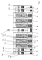
- FIG. 1 shows a switchgear assembly 1, e. g. as used for DC power distribution in a data center.
- the switchgear assembly 1 comprises a number of modules or cabinets which are arranged side by side and electrically interconnected.
- the switchgear assembly 1 has a main breaker module 2 or a main breaker cabinet including a main breaker 21 which is connected to an AC power supply of a common grid or a transformer for galvanic insulation or the like.
- the main breaker module 2 is a separate module/cabinet having multiple AC supply bus bars 22, one per each phase.
- the multiple AC supply bus bars 22 are part of a single AC supply bus 6 formed with AC supply bus bars of other coupled modules and configured to be easily coupled or connected with the AC supply bus bars of the other coupled modules.
- an HMI (Human Machine Interface) 23 is provided to display system status information.
- the main breaker module 2 is coupled to a number of AC/DC converter modules 4 (four in the present embodiment).
- Each of the AC/DC converter modules 4 includes an AC/DC converter unit 41.
- AC power is supplied to each of the AC/DC converter units 41 via the AC supply bus bars 42 of the AC/DC converter module 4 which is configured to be coupleable to AC supply bus bars of other modules, e. g. to be coupled to one another and to the AC power distribution bus 22 of the main breaker module 2, to form the AC supply bus 6.
- a line-up of a number of AC/DC converter modules 4 can be built.
- FIG 2 an example of an AC/DC converter unit 41 based on a 3-level active front-end converter 43 and a 3-level buck converter 44 is shown, wherein an output of the 3-level active front-end converter 43 and an input of the 3-level buck converter 44 are coupled via DC link capacitors 45.
- the DC link capacitors 45 can be connected to a DC source battery string 46, in particular for feeding on a 750 VDC internal DC level.
- a separated battery module (or cabinet or cubicle) 5 can be coupled to each of the AC/DC converter modules 4.
- the DC source battery string 46 of each AC/DC converter module 4 can be provided with an additional DC circuit breaker 47 to protect the battery module 5 and/or the AC/DC converter unit 41.
- the AC/DC converter modules 4 may be provided with the battery modules 5 which can be included in the AC/DC converter module 4.
- the battery modules 5 can be arranged separately and electrically connected to the DC source battery string 46 of the AC/DC converter module 4.
- the DC output of the AC/DC converter unit 41 is coupled to DC power distribution bus bars 48.
- the DC power distribution bus bars 48 of the AC/DC converter modules 4 are coupled or configured to be coupled to each other to form a common DC power distribution bus 7 which passes through the AC/DC converter modules 4. Therefore any number of AC/DC converter modules 4 can be coupled to provide a DC distribution bus 7 passing through all of the coupled AC/DC converter modules 4.
- the DC power distribution bus bars 48 of the DC power distribution system will provide a floating ground system which allows highest reliability as not even the first ground fault will cause a system shutdown.
- an earth fault supervision system may be provided in each of the AC/DC converter units 41 to indicate the ground fault and to allow the operator to identify the fault area and to repair it even online.
- the above AC/DC converter modules 4 for use in the switchgear assembly 1 allow for a higher flexibility and reliability with lower investment and operational costs on a higher level of maintainability.
- each of the first circuit breaker modules 9 has AC main supply bus bars 91 coupled to one another and to the main breaker module 2.
- each first circuit breaker module 7 includes a respective circuit breaker 92 a first terminal of which is coupled to the respective AC main supply bus bar 91 and a second terminal of which is coupled via a respective first connection C1 to the corresponding AC/DC converter modules 4.
- the DC power distribution bus bars 48 of the AC/DC converter modules 4 are coupled via separate second circuit breaker modules 8 / a second circuit breaker cabinet, respectively, to the DC power distribution bus 7. Therefore, the outputs of the AC/DC units 41 are coupled via second connections C2 to the second circuit breaker modules 8.
- the DC power distribution bus 7 is formed by the DC power distribution bus bars 81 in the second circuit breaker modules 8 which are coupled to each other.
- the main breaker module 2 can be further coupled to AC/AC converter modules 11.
- the AC/AC converter modules 11 can be provided in any number (three in the present embodiment) depending on the requirements of the consumer loads in the data center.
- the AC/AC converter modules 11 comprise AC/AC converter units 111 which receive AC power supply via the AC supply bus bars 112 of the AC/AC converter module 11.
- the AC supply bus bars 112 together with the AC supply bus bars 22 of the main breaker module 2 and the AC supply bus bars 42 of the AC/DC converter modules 4 form the common AC supply bus 6.
- the AC/AC converter units 111 receive AC supply power from the thus formed AC supply bus 6 and output converted AC power on AC power distribution bus bars 113.
- the AC power distribution bus bars 113 are coupled to each other to form an AC power distribution bus 22.
- the AC supply bus bars 112 are coupled to the AC supply bus bars 22 of the main breaker module 2, so that the AC supply power is distributed over all AC/AC converter modules 11. Furthermore, the AC power distribution bus 12 comprises AC power distribution bus bars 113 which pass through all of the AC/AC converter modules 11.
- the AC/DC converter modules 4 can be coupled via the DC power distribution bus 7 to DC feeder modules 13 which are configured to couple the DC power distribution bus 7 to respective consumer loads (not shown).
- the DC feeder modules 13 may comprise respective breakers 131 for switching consumer loads supplied with DC power.
- AC feeder modules 14 are provided which comprise AC power distribution bus bars 141 to be coupled to the AC power distribution bus bars 113 of the AC/AC converter modules 11, so that the AC power output by the AC/AC converter units 111 can be fed via respective breakers 142 to consumer loads powered with AC current.
- the above configuration provides an increased reliability as the converter units, i. e. the AC/DC converter units 41 and the AC/AC converter units 111, are coupled in parallel, so that even if one complete rectifier string fails or is shut down for maintenance the system will remain in operation as long as the required total power does not exceed the power capacity of the converter units 41, 111 that remain active.
- the system allows the standard extension possibilities of a switchgear assembly. Hence, it is possible to connect the main distribution and subdistribution on the DC part directly to the main bus bar system as well as to connect AC parts like AC distribution for lightning or air conditioning or an additional incoming section for the generator.
Landscapes
- Engineering & Computer Science (AREA)
- Power Engineering (AREA)
- Business, Economics & Management (AREA)
- Emergency Management (AREA)
- Direct Current Feeding And Distribution (AREA)
Abstract
- one or more AC supply bus bars (42, 112) for providing AC power supply;
- one or more AC or DC power distribution bus bars (48, 113) for distributing power to loads; and
- one or more converter units (41, 111) for converting AC power from the AC supply bus bars (42, 112) to AC or DC power onto AC or DC power distribution bus bars (48, 113), respectively.
Description
- The present invention relates to a converter module for use in a modularized switchgear assembly for power distribution systems for supplying AC and/or DC power to a consumer load, in particular to a data center.
- Common electrical switchgear assemblies are predominantly designed using so-called withdrawable part technology and/or modularized devices, wherein the operating means and devices for processing, control, measuring and switching are arranged on or in withdrawable parts and/or exchangeable modules or cabinets.
- The withdrawable part technology provides a simplified access in case of fault or maintenance activities because the parts in question can easily be removed from the housing and therefore checked, repaired, exchanged or replaced without any considerable dismantling work.
- Today's data center setups use stand-alone AC/DC and AC/AC converter units with uninterruptible power supplies to secure the energy supply of the data center. This configuration requires independent components to transfer the power from the medium-voltage level to a reliable uninterruptible supply on the low-voltage side for the server racks in the data center.
- Common switchgear assemblies for data centers use separate stand-alone uninterruptable power supply (UPS) modules to ensure and secure a permanent energy supply to the consumers of the data center or any other connected consumer loads. In conventional assemblies, the configuration of the converter units hence needs to be dimensioned separately from the auxiliary power supply provided by the stand-alone UPS modules.
- A disadvantage of such an assembly with stand-alone UPS modules is the additional effort required for engineering, commissioning and maintenance as well as costs and energy of thermal losses induced by cabling and the provision of additional breakers.
- It is therefore an object of the present invention to provide a converter module and switchgear assembly with one or more converters having a power distribution system for providing AC and/or DC power, e. g. for a data center, which further provide an uninterruptable power supply for the AC and/or DC power and which can easily be customized according to the specific power requirements of the data center.
- This object has been achieved by the converter module for use in a switchgear assembly, in particular a low voltage switchgear assembly, to provide AC and/or DC power according to
claim 1 and by the switchgear assembly for power distribution and the power distribution system according to the further independent claims. - Further embodiments and refinements are indicated in the dependent subclaims and the following description.
- According to a first aspect, a converter module for use in a switchgear assembly, in particular a low voltage switchgear assembly, for power distribution is provided, comprising:
- one or more AC supply bus bars for providing AC power supply;
- one or more AC or DC power distribution bus bars for distributing power to loads; and
- one or more converter units for converting AC power from the AC supply bus bars to AC or DC power onto AC or DC power distribution bus bars, respectively.
- The above converter module for use in a switchgear assembly allows for a higher flexibility and reliability with lower investment and operational costs on a higher level of maintainability.
- Furthermore, the AC supply bus bars are configured to form an AC supply bus with AC supply bus bars of one or more other coupled modules.
- Moreover, the converter unit is configured to convert AC power to AC power onto the AC power distribution bus bars, wherein the AC power distribution bus bars are configured to form the AC power distribution bus with coupled AC supply bus bars of one or more other coupled modules.
- According to an embodiment, the converter unit may be configured to convert AC power to DC power onto the DC power distribution bus bars, wherein the DC power distribution bus bars are configured to form the DC power distribution bus with coupled DC supply bus bars of one or more other coupled modules.
- It may be provided that the converter unit comprises an active front end and a buck converter which are coupled through a DC link, wherein a battery unit of a UPS, which is provided internally or externally of a cabinet of the converter module, is coupled via the DC link.
- The converter module may form a separate cabinet or cubicle.
- According to a further aspect, a switchgear assembly is provided, comprising:
- a main breaker module including a general circuit breaker for switching an AC supply bus; and
- at least one of
- ○ one or more AC/DC converter modules for converting AC power from the AC supply bus to DC power onto a DC power distribution bus; and
- ○ one or more AC/AC converter modules for converting AC power from the AC supply bus to AC power onto an AC power distribution bus,
- Moreover, the converter modules may be coupled in parallel with their AC supply bus bars.
- Particularly, the converter modules may be coupled in parallel to their AC or DC power distribution bus bars.
- It may be provided that the converter modules are coupled to the AC power supply via respective first circuit breaker modules and/or to the respective power distribution bus via second circuit breaker modules.
- According to a further aspect, a power distribution system for a switchgear assembly, in particular a low voltage switchgear assembly, is provided, including:
- an AC supply bus for providing an AC power supply;
- a DC power distribution bus for providing DC power and/or an AC power distribution bus for providing AC power;
- a general circuit breaker for switching the AC supply bus;
- one or more AC/DC converter units for converting AC power from the AC supply bus to DC power onto the DC power distribution bus; and/or
- one or more AC/AC converter units for converting AC power from the AC supply bus to AC power onto the AC power distribution bus.
- Embodiments are described in more detail in conjunction with the accompanying drawings in which:
- Figure 1
- shows a switchgear assembly for DC power distribution using converter modules;
- Figure 2
- shows an example of a DC converter unit based on an active front end and a buck converter;
- Figure 3
- shows a further embodiment of a switchgear assembly for DC power distribution using converter modules; and
- Figure 4
- shows a further embodiment of a switchgear assembly for AC and DC power distribution.
-
Figure 1 shows aswitchgear assembly 1, e. g. as used for DC power distribution in a data center. Theswitchgear assembly 1 comprises a number of modules or cabinets which are arranged side by side and electrically interconnected. - The
switchgear assembly 1 has amain breaker module 2 or a main breaker cabinet including amain breaker 21 which is connected to an AC power supply of a common grid or a transformer for galvanic insulation or the like. Themain breaker module 2 is a separate module/cabinet having multiple AC supply bus bars 22, one per each phase. The multiple AC supply bus bars 22 are part of a singleAC supply bus 6 formed with AC supply bus bars of other coupled modules and configured to be easily coupled or connected with the AC supply bus bars of the other coupled modules. - Furthermore, an HMI (Human Machine Interface) 23 is provided to display system status information.
- In the present embodiment, the
main breaker module 2 is coupled to a number of AC/DC converter modules 4 (four in the present embodiment). Each of the AC/DC converter modules 4 includes an AC/DC converter unit 41. AC power is supplied to each of the AC/DC converter units 41 via the ACsupply bus bars 42 of the AC/DC converter module 4 which is configured to be coupleable to AC supply bus bars of other modules, e. g. to be coupled to one another and to the AC power distribution bus 22 of themain breaker module 2, to form theAC supply bus 6. Hence, a line-up of a number of AC/DC converter modules 4 can be built. - In
Figure 2 , an example of an AC/DC converter unit 41 based on a 3-level active front-end converter 43 and a 3-level buck converter 44 is shown, wherein an output of the 3-level active front-end converter 43 and an input of the 3-level buck converter 44 are coupled viaDC link capacitors 45. TheDC link capacitors 45 can be connected to a DCsource battery string 46, in particular for feeding on a 750 VDC internal DC level. - Via the DC
source battery string 46 of each AC/DC converter module 4, a separated battery module (or cabinet or cubicle) 5 can be coupled to each of the AC/DC converter modules 4. The DCsource battery string 46 of each AC/DC converter module 4 can be provided with an additionalDC circuit breaker 47 to protect thebattery module 5 and/or the AC/DC converter unit 41. - The AC/
DC converter modules 4 may be provided with thebattery modules 5 which can be included in the AC/DC converter module 4. Alternatively, thebattery modules 5 can be arranged separately and electrically connected to the DCsource battery string 46 of the AC/DC converter module 4. - The DC output of the AC/
DC converter unit 41 is coupled to DC power distribution bus bars 48. The DC power distribution bus bars 48 of the AC/DC converter modules 4 are coupled or configured to be coupled to each other to form a common DCpower distribution bus 7 which passes through the AC/DC converter modules 4. Therefore any number of AC/DC converter modules 4 can be coupled to provide aDC distribution bus 7 passing through all of the coupled AC/DC converter modules 4. - The DC power distribution bus bars 48 of the DC power distribution system will provide a floating ground system which allows highest reliability as not even the first ground fault will cause a system shutdown. In combination with the floating ground system, an earth fault supervision system may be provided in each of the AC/
DC converter units 41 to indicate the ground fault and to allow the operator to identify the fault area and to repair it even online. - The above AC/
DC converter modules 4 for use in theswitchgear assembly 1 allow for a higher flexibility and reliability with lower investment and operational costs on a higher level of maintainability. - In
Figure 3 , a different configuration of theswitchgear assembly 10 is shown. In contrast to theswitchgear assembly 1 as shown inFigure 1 , the AC/DC converter modules 4 are connected to theAC source 3 separately via respective firstcircuit breaker modules 9 coupled between themain breaker module 2 and the respective AC/DC converter module 4. Each of the firstcircuit breaker modules 9 has AC main supply bus bars 91 coupled to one another and to themain breaker module 2. Moreover, each firstcircuit breaker module 7 includes a respective circuit breaker 92 a first terminal of which is coupled to the respective AC mainsupply bus bar 91 and a second terminal of which is coupled via a respective first connection C1 to the corresponding AC/DC converter modules 4. - The DC power distribution bus bars 48 of the AC/
DC converter modules 4 are coupled via separate secondcircuit breaker modules 8 / a second circuit breaker cabinet, respectively, to the DCpower distribution bus 7. Therefore, the outputs of the AC/DC units 41 are coupled via second connections C2 to the secondcircuit breaker modules 8. The DCpower distribution bus 7 is formed by the DC power distribution bus bars 81 in the secondcircuit breaker modules 8 which are coupled to each other. - As shown in the further embodiment of
Figure 4 , in addition to the embodiment ofFigure 1 , themain breaker module 2 can be further coupled to AC/AC converter modules 11. The AC/AC converter modules 11 can be provided in any number (three in the present embodiment) depending on the requirements of the consumer loads in the data center. The AC/AC converter modules 11 comprise AC/AC converter units 111 which receive AC power supply via the ACsupply bus bars 112 of the AC/AC converter module 11. The AC supply bus bars 112 together with the AC supply bus bars 22 of themain breaker module 2 and the AC supply bus bars 42 of the AC/DC converter modules 4 form the commonAC supply bus 6. - The AC/
AC converter units 111 receive AC supply power from the thus formedAC supply bus 6 and output converted AC power on AC power distribution bus bars 113. The AC power distribution bus bars 113 are coupled to each other to form an AC power distribution bus 22. - The AC
supply bus bars 112 are coupled to the AC supply bus bars 22 of themain breaker module 2, so that the AC supply power is distributed over all AC/AC converter modules 11. Furthermore, the ACpower distribution bus 12 comprises AC power distribution bus bars 113 which pass through all of the AC/AC converter modules 11. - The AC/
DC converter modules 4 can be coupled via the DCpower distribution bus 7 toDC feeder modules 13 which are configured to couple the DCpower distribution bus 7 to respective consumer loads (not shown). TheDC feeder modules 13 may compriserespective breakers 131 for switching consumer loads supplied with DC power. Similarly,AC feeder modules 14 are provided which comprise AC power distribution bus bars 141 to be coupled to the AC power distribution bus bars 113 of the AC/AC converter modules 11, so that the AC power output by the AC/AC converter units 111 can be fed viarespective breakers 142 to consumer loads powered with AC current. - The above configuration provides an increased reliability as the converter units, i. e. the AC/
DC converter units 41 and the AC/AC converter units 111, are coupled in parallel, so that even if one complete rectifier string fails or is shut down for maintenance the system will remain in operation as long as the required total power does not exceed the power capacity of theconverter units - Next to the main line-up with the
main breaker module 2 and the AC/DC converter module 4, the system allows the standard extension possibilities of a switchgear assembly. Hence, it is possible to connect the main distribution and subdistribution on the DC part directly to the main bus bar system as well as to connect AC parts like AC distribution for lightning or air conditioning or an additional incoming section for the generator.
Claims (11)
- Converter module (4, 11) for use in a switchgear assembly (1) for power distribution, comprising:- one or more AC supply bus bars (42, 112) for providing AC power supply;- one or more AC or DC power distribution bus bars (48, 113) for distributing power to loads; and- one or more converter units (41, 111) for converting AC power from the AC supply bus bars (42, 112) to AC or DC power onto AC or DC power distribution bus bars (48, 113), respectively.
- Converter module (4, 11) according to claim 1, wherein the AC supply bus bars (42, 112) are configured to form an AC supply bus (6) with AC sup-ply bus bars (42, 112) of one or more other coupled modules.
- Converter module (11) according to claim 1 or 2, wherein the converter unit (111) is configured to convert AC power to AC power onto the AC power distribution bus bars (113), wherein the AC power distribution bus bars (113) are configured to form the AC power distribution bus (12) with coupled AC power distribution bus bars of one or more other coupled modules.
- Converter module (4) according to claim 1 or 2, wherein the converter unit (41) is configured to convert AC power to DC power onto the DC power distribution bus bars (48), wherein the DC power distribution bus bars (48) are configured to form the DC power distribution bus (7) with coupled DC power distribution bus bars of one or more other coupled modules.
- Converter module (4) according to claim 4, wherein the converter unit (41) comprises an active front-end converter (43) and a buck converter (44) which are coupled through a DC link, wherein a UPS battery unit (5), which is provided internally or externally of a cabinet of the converter module, is coupled via the DC link.
- Converter module (4, 11) according to any one of claims 1 to 5, wherein the converter module forms a separate cabinet or cubicle.
- A switchgear assembly (1) comprising:- a main breaker module (2) including a general circuit breaker (21) for switching an AC supply bus (6); and- at least one of○ one or more AC/DC converter modules (4) according to any one of claims 1 to 6 for converting AC power from the AC supply bus (6) to DC power onto a DC power distribution bus (7); and○ one or more AC/AC converter modules (11) according to any one of claims 1 to 6 for converting AC power from the AC supply bus (6) to AC power onto a AC power distribution bus (12).
- A switchgear assembly (1) according to claim 7, wherein the converter modules are coupled in parallel to their AC supply bus bars (42, 112).
- A switchgear assembly (1) according to claim 7 or 8, wherein the converter modules are coupled in parallel with their AC or DC power distribution bus bars (48, 113).
- A switchgear assembly (1) according to claim 7, wherein the converter modules are coupled with an AC supply (3) via respective first circuit breaker modules (9) and/or with the respective power distribution bus via second circuit breaker modules (8).
- A power distribution system for a switchgear assembly (1) including:- an AC supply bus (6) for providing an AC power supply;- a DC power distribution bus (7) for providing DC power and/or an AC power distribution bus for providing AC power;- a general circuit breaker for switching the AC supply bus (6);- one or more AC/DC converter units (41) for converting AC power from the AC supply bus (6) to DC power onto the DC power distribution bus (7); and/or- one or more AC/AC converter units (111) for converting AC power from the AC supply bus (6) to AC power onto the AC power distribution bus (22).
Priority Applications (4)
| Application Number | Priority Date | Filing Date | Title |
|---|---|---|---|
| EP13005972.8A EP2887484B1 (en) | 2013-12-20 | 2013-12-20 | Switchgear assembly for AC and DC power distribution |
| PCT/EP2014/077210 WO2015091154A1 (en) | 2013-12-20 | 2014-12-10 | Converter module and switchgear assembly for ac and dc power distribution |
| US15/106,331 US10090703B2 (en) | 2013-12-20 | 2014-12-10 | Converter module and switchgear assembly for AC and DC power distribution |
| CN201480069906.7A CN106030952A (en) | 2013-12-20 | 2014-12-10 | Converter module and switchgear assembly for ac and dc power distribution |
Applications Claiming Priority (1)
| Application Number | Priority Date | Filing Date | Title |
|---|---|---|---|
| EP13005972.8A EP2887484B1 (en) | 2013-12-20 | 2013-12-20 | Switchgear assembly for AC and DC power distribution |
Publications (2)
| Publication Number | Publication Date |
|---|---|
| EP2887484A1 true EP2887484A1 (en) | 2015-06-24 |
| EP2887484B1 EP2887484B1 (en) | 2023-06-28 |
Family
ID=49911088
Family Applications (1)
| Application Number | Title | Priority Date | Filing Date |
|---|---|---|---|
| EP13005972.8A Active EP2887484B1 (en) | 2013-12-20 | 2013-12-20 | Switchgear assembly for AC and DC power distribution |
Country Status (4)
| Country | Link |
|---|---|
| US (1) | US10090703B2 (en) |
| EP (1) | EP2887484B1 (en) |
| CN (1) | CN106030952A (en) |
| WO (1) | WO2015091154A1 (en) |
Cited By (4)
| Publication number | Priority date | Publication date | Assignee | Title |
|---|---|---|---|---|
| JP2021019367A (en) * | 2019-07-17 | 2021-02-15 | 富士電機株式会社 | Uninterruptible power supply device |
| CN113890007A (en) * | 2020-07-02 | 2022-01-04 | 中国移动通信集团设计院有限公司 | Prepackage type power supply and distribution system |
| US11296544B2 (en) | 2019-10-16 | 2022-04-05 | Fuji Electric Co., Ltd. | Uninterruptible power supply and disconnection module |
| WO2023060080A1 (en) * | 2021-10-08 | 2023-04-13 | GE Grid GmbH | Systems and methods for a modular scalable architecture for energy storage auxiliary power and functions |
Families Citing this family (8)
| Publication number | Priority date | Publication date | Assignee | Title |
|---|---|---|---|---|
| US10404062B2 (en) * | 2016-04-21 | 2019-09-03 | Nuscale Power, Llc | Fault-tolerant power-distribution modules for a power plant |
| US10424887B2 (en) * | 2017-04-03 | 2019-09-24 | Arista Networks, Inc. | Hybrid power delivery assembly |
| KR102299860B1 (en) * | 2018-09-13 | 2021-09-09 | 엘에스일렉트릭 (주) | Module for supplying power and system for supplying power |
| US12095308B2 (en) | 2018-09-13 | 2024-09-17 | Ls Electric Co., Ltd. | Power supply device and power supply system |
| KR102142456B1 (en) * | 2018-09-20 | 2020-08-07 | 엘에스일렉트릭(주) | Power Supplying Device |
| AU2019435207B2 (en) | 2019-03-15 | 2024-12-19 | Ge Grid Solutions Llc | Customizable power converter and customizable power conversion system |
| US10847954B1 (en) | 2019-04-17 | 2020-11-24 | Faith Technologies, Inc. | Temporary direct current power system |
| EP4052350B1 (en) * | 2019-10-28 | 2023-12-06 | Vertiv Corporation | Uninterruptible power supply system having stranded power recovery |
Citations (3)
| Publication number | Priority date | Publication date | Assignee | Title |
|---|---|---|---|---|
| US20050162792A1 (en) * | 2004-01-22 | 2005-07-28 | Shyne-Jenq Wang | Emergent power supply system and method of achieving input current balance in such system |
| US20100102636A1 (en) * | 2006-03-10 | 2010-04-29 | Eaton Corporation | Nested redundant uninterruptible power supply apparatus and methods |
| US20110006607A1 (en) * | 2009-07-10 | 2011-01-13 | Electronics And Telecommunications Research Institute | Hybrid power supply apparatus for data center |
Family Cites Families (4)
| Publication number | Priority date | Publication date | Assignee | Title |
|---|---|---|---|---|
| JP3908076B2 (en) | 2002-04-16 | 2007-04-25 | 株式会社日立製作所 | DC backup power supply |
| CN202663130U (en) * | 2011-12-02 | 2013-01-09 | 中兴通讯股份有限公司 | Power supply cabinet |
| US9419475B2 (en) * | 2012-08-23 | 2016-08-16 | Eaton Corporation | UPS systems with modular block architectures |
| EP2709229B1 (en) * | 2012-09-17 | 2015-03-25 | GE Energy Power Conversion Technology Ltd | Power distribution systems |
-
2013
- 2013-12-20 EP EP13005972.8A patent/EP2887484B1/en active Active
-
2014
- 2014-12-10 CN CN201480069906.7A patent/CN106030952A/en active Pending
- 2014-12-10 WO PCT/EP2014/077210 patent/WO2015091154A1/en not_active Ceased
- 2014-12-10 US US15/106,331 patent/US10090703B2/en active Active
Patent Citations (3)
| Publication number | Priority date | Publication date | Assignee | Title |
|---|---|---|---|---|
| US20050162792A1 (en) * | 2004-01-22 | 2005-07-28 | Shyne-Jenq Wang | Emergent power supply system and method of achieving input current balance in such system |
| US20100102636A1 (en) * | 2006-03-10 | 2010-04-29 | Eaton Corporation | Nested redundant uninterruptible power supply apparatus and methods |
| US20110006607A1 (en) * | 2009-07-10 | 2011-01-13 | Electronics And Telecommunications Research Institute | Hybrid power supply apparatus for data center |
Non-Patent Citations (2)
| Title |
|---|
| ABB: "MNS Low Voltage Switchgear System Guide", 31 December 2012 (2012-12-31), XP055117179, Retrieved from the Internet <URL:http://www05.abb.com/global/scot/scot209.nsf/veritydisplay/a4d3ca5ddcf0c4dbc1257a9800150f36/$file/MNS_System_Guide_1TGC902030B0204_Rev04%20print.pdf> [retrieved on 20140509] * |
| DE JONG & P T M VAESSEN E C W: "DC power distribution for server farms", INTERNET CITATION, September 2007 (2007-09-01), pages 1 - 14, XP002716084, Retrieved from the Internet <URL:http://leonardo-energy.dev.o-a.be/sites/leonardo-energy/files/root/pdf/2007/DCServerFarms.pdf> [retrieved on 20131107] * |
Cited By (6)
| Publication number | Priority date | Publication date | Assignee | Title |
|---|---|---|---|---|
| JP2021019367A (en) * | 2019-07-17 | 2021-02-15 | 富士電機株式会社 | Uninterruptible power supply device |
| US11296544B2 (en) | 2019-10-16 | 2022-04-05 | Fuji Electric Co., Ltd. | Uninterruptible power supply and disconnection module |
| CN113890007A (en) * | 2020-07-02 | 2022-01-04 | 中国移动通信集团设计院有限公司 | Prepackage type power supply and distribution system |
| CN113890007B (en) * | 2020-07-02 | 2023-11-21 | 中国移动通信集团设计院有限公司 | Preassembled power supply and distribution system |
| WO2023060080A1 (en) * | 2021-10-08 | 2023-04-13 | GE Grid GmbH | Systems and methods for a modular scalable architecture for energy storage auxiliary power and functions |
| US12003098B2 (en) | 2021-10-08 | 2024-06-04 | GE Grid GmbH | Systems and methods for a modular scalable architecture for energy storage auxiliary power and functions |
Also Published As
| Publication number | Publication date |
|---|---|
| US20170005514A1 (en) | 2017-01-05 |
| CN106030952A (en) | 2016-10-12 |
| US10090703B2 (en) | 2018-10-02 |
| EP2887484B1 (en) | 2023-06-28 |
| WO2015091154A1 (en) | 2015-06-25 |
Similar Documents
| Publication | Publication Date | Title |
|---|---|---|
| US10090703B2 (en) | Converter module and switchgear assembly for AC and DC power distribution | |
| US11196288B2 (en) | Direct current power supply system | |
| RU2566811C2 (en) | Uninterrupted power supply unit, power supply system and usage of uninterrupted power supply unit | |
| EP3625870B1 (en) | Virtualization of power for data centers, telecom environments and equivalent infrastructures | |
| EP2227845B1 (en) | Switchboard with ups and horizontal busbars | |
| AU2016101769A4 (en) | Power system and method | |
| CN105379052A (en) | UPS systems and methods using variable configuration modules | |
| CN101826748A (en) | System and method for supplying power to electronics enclosures utilizing distributed DC power architectures | |
| KR101789335B1 (en) | Modular dc power supply | |
| EP2790286A1 (en) | Switchgear assembly, DC power distribution system, DC power distribution board | |
| US9923414B2 (en) | System for redundant power supply to a data center | |
| EP4262040A1 (en) | Power supply and distribution system for data center | |
| EP2887782A1 (en) | Switchgear assembly and power distribution system | |
| US20120230072A1 (en) | Circuit assembly having a converter part comprising a central control unit | |
| Lisy et al. | Three case studies of commercial deployment of 400V DC data and telecom centers in the EMEA region | |
| CN214755701U (en) | Power supply system | |
| UA128724C2 (en) | Modularly constructed push-in transducer unit and instrumentation and control power supply system for a nuclear power plant | |
| EP4216392A1 (en) | Power conversion system | |
| CN210490468U (en) | Power distribution system and clean factory building | |
| JP6713840B2 (en) | Power system | |
| Park et al. | Electrical Design in Data Centers |
Legal Events
| Date | Code | Title | Description |
|---|---|---|---|
| PUAI | Public reference made under article 153(3) epc to a published international application that has entered the european phase |
Free format text: ORIGINAL CODE: 0009012 |
|
| 17P | Request for examination filed |
Effective date: 20131220 |
|
| AK | Designated contracting states |
Kind code of ref document: A1 Designated state(s): AL AT BE BG CH CY CZ DE DK EE ES FI FR GB GR HR HU IE IS IT LI LT LU LV MC MK MT NL NO PL PT RO RS SE SI SK SM TR |
|
| AX | Request for extension of the european patent |
Extension state: BA ME |
|
| R17P | Request for examination filed (corrected) |
Effective date: 20150702 |
|
| STAA | Information on the status of an ep patent application or granted ep patent |
Free format text: STATUS: EXAMINATION IS IN PROGRESS |
|
| 17Q | First examination report despatched |
Effective date: 20190816 |
|
| REG | Reference to a national code |
Ref country code: DE Ref legal event code: R079 Free format text: PREVIOUS MAIN CLASS: H02J0001100000 Ipc: H02J0004000000 Ref country code: DE Ref legal event code: R079 Ref document number: 602013084113 Country of ref document: DE Free format text: PREVIOUS MAIN CLASS: H02J0001100000 Ipc: H02J0004000000 |
|
| RIC1 | Information provided on ipc code assigned before grant |
Ipc: H02M 7/493 20070101ALI20221130BHEP Ipc: H02J 9/06 20060101ALI20221130BHEP Ipc: H02J 1/10 20060101ALI20221130BHEP Ipc: H02J 4/00 20060101AFI20221130BHEP |
|
| GRAP | Despatch of communication of intention to grant a patent |
Free format text: ORIGINAL CODE: EPIDOSNIGR1 |
|
| STAA | Information on the status of an ep patent application or granted ep patent |
Free format text: STATUS: GRANT OF PATENT IS INTENDED |
|
| INTG | Intention to grant announced |
Effective date: 20230201 |
|
| GRAS | Grant fee paid |
Free format text: ORIGINAL CODE: EPIDOSNIGR3 |
|
| GRAA | (expected) grant |
Free format text: ORIGINAL CODE: 0009210 |
|
| STAA | Information on the status of an ep patent application or granted ep patent |
Free format text: STATUS: THE PATENT HAS BEEN GRANTED |
|
| AK | Designated contracting states |
Kind code of ref document: B1 Designated state(s): AL AT BE BG CH CY CZ DE DK EE ES FI FR GB GR HR HU IE IS IT LI LT LU LV MC MK MT NL NO PL PT RO RS SE SI SK SM TR |
|
| REG | Reference to a national code |
Ref country code: CH Ref legal event code: EP |
|
| REG | Reference to a national code |
Ref country code: AT Ref legal event code: REF Ref document number: 1583604 Country of ref document: AT Kind code of ref document: T Effective date: 20230715 |
|
| REG | Reference to a national code |
Ref country code: IE Ref legal event code: FG4D |
|
| REG | Reference to a national code |
Ref country code: DE Ref legal event code: R096 Ref document number: 602013084113 Country of ref document: DE |
|
| REG | Reference to a national code |
Ref country code: LT Ref legal event code: MG9D |
|
| PG25 | Lapsed in a contracting state [announced via postgrant information from national office to epo] |
Ref country code: SE Free format text: LAPSE BECAUSE OF FAILURE TO SUBMIT A TRANSLATION OF THE DESCRIPTION OR TO PAY THE FEE WITHIN THE PRESCRIBED TIME-LIMIT Effective date: 20230628 Ref country code: NO Free format text: LAPSE BECAUSE OF FAILURE TO SUBMIT A TRANSLATION OF THE DESCRIPTION OR TO PAY THE FEE WITHIN THE PRESCRIBED TIME-LIMIT Effective date: 20230928 |
|
| REG | Reference to a national code |
Ref country code: NL Ref legal event code: MP Effective date: 20230628 |
|
| REG | Reference to a national code |
Ref country code: AT Ref legal event code: MK05 Ref document number: 1583604 Country of ref document: AT Kind code of ref document: T Effective date: 20230628 |
|
| PG25 | Lapsed in a contracting state [announced via postgrant information from national office to epo] |
Ref country code: RS Free format text: LAPSE BECAUSE OF FAILURE TO SUBMIT A TRANSLATION OF THE DESCRIPTION OR TO PAY THE FEE WITHIN THE PRESCRIBED TIME-LIMIT Effective date: 20230628 Ref country code: NL Free format text: LAPSE BECAUSE OF FAILURE TO SUBMIT A TRANSLATION OF THE DESCRIPTION OR TO PAY THE FEE WITHIN THE PRESCRIBED TIME-LIMIT Effective date: 20230628 Ref country code: LV Free format text: LAPSE BECAUSE OF FAILURE TO SUBMIT A TRANSLATION OF THE DESCRIPTION OR TO PAY THE FEE WITHIN THE PRESCRIBED TIME-LIMIT Effective date: 20230628 Ref country code: LT Free format text: LAPSE BECAUSE OF FAILURE TO SUBMIT A TRANSLATION OF THE DESCRIPTION OR TO PAY THE FEE WITHIN THE PRESCRIBED TIME-LIMIT Effective date: 20230628 Ref country code: HR Free format text: LAPSE BECAUSE OF FAILURE TO SUBMIT A TRANSLATION OF THE DESCRIPTION OR TO PAY THE FEE WITHIN THE PRESCRIBED TIME-LIMIT Effective date: 20230628 Ref country code: GR Free format text: LAPSE BECAUSE OF FAILURE TO SUBMIT A TRANSLATION OF THE DESCRIPTION OR TO PAY THE FEE WITHIN THE PRESCRIBED TIME-LIMIT Effective date: 20230929 |
|
| PG25 | Lapsed in a contracting state [announced via postgrant information from national office to epo] |
Ref country code: FI Free format text: LAPSE BECAUSE OF FAILURE TO SUBMIT A TRANSLATION OF THE DESCRIPTION OR TO PAY THE FEE WITHIN THE PRESCRIBED TIME-LIMIT Effective date: 20230628 |
|
| PG25 | Lapsed in a contracting state [announced via postgrant information from national office to epo] |
Ref country code: SK Free format text: LAPSE BECAUSE OF FAILURE TO SUBMIT A TRANSLATION OF THE DESCRIPTION OR TO PAY THE FEE WITHIN THE PRESCRIBED TIME-LIMIT Effective date: 20230628 |
|
| PG25 | Lapsed in a contracting state [announced via postgrant information from national office to epo] |
Ref country code: ES Free format text: LAPSE BECAUSE OF FAILURE TO SUBMIT A TRANSLATION OF THE DESCRIPTION OR TO PAY THE FEE WITHIN THE PRESCRIBED TIME-LIMIT Effective date: 20230628 |
|
| PG25 | Lapsed in a contracting state [announced via postgrant information from national office to epo] |
Ref country code: IS Free format text: LAPSE BECAUSE OF FAILURE TO SUBMIT A TRANSLATION OF THE DESCRIPTION OR TO PAY THE FEE WITHIN THE PRESCRIBED TIME-LIMIT Effective date: 20231028 |
|
| PG25 | Lapsed in a contracting state [announced via postgrant information from national office to epo] |
Ref country code: SM Free format text: LAPSE BECAUSE OF FAILURE TO SUBMIT A TRANSLATION OF THE DESCRIPTION OR TO PAY THE FEE WITHIN THE PRESCRIBED TIME-LIMIT Effective date: 20230628 Ref country code: SK Free format text: LAPSE BECAUSE OF FAILURE TO SUBMIT A TRANSLATION OF THE DESCRIPTION OR TO PAY THE FEE WITHIN THE PRESCRIBED TIME-LIMIT Effective date: 20230628 Ref country code: RO Free format text: LAPSE BECAUSE OF FAILURE TO SUBMIT A TRANSLATION OF THE DESCRIPTION OR TO PAY THE FEE WITHIN THE PRESCRIBED TIME-LIMIT Effective date: 20230628 Ref country code: PT Free format text: LAPSE BECAUSE OF FAILURE TO SUBMIT A TRANSLATION OF THE DESCRIPTION OR TO PAY THE FEE WITHIN THE PRESCRIBED TIME-LIMIT Effective date: 20231030 Ref country code: IS Free format text: LAPSE BECAUSE OF FAILURE TO SUBMIT A TRANSLATION OF THE DESCRIPTION OR TO PAY THE FEE WITHIN THE PRESCRIBED TIME-LIMIT Effective date: 20231028 Ref country code: ES Free format text: LAPSE BECAUSE OF FAILURE TO SUBMIT A TRANSLATION OF THE DESCRIPTION OR TO PAY THE FEE WITHIN THE PRESCRIBED TIME-LIMIT Effective date: 20230628 Ref country code: EE Free format text: LAPSE BECAUSE OF FAILURE TO SUBMIT A TRANSLATION OF THE DESCRIPTION OR TO PAY THE FEE WITHIN THE PRESCRIBED TIME-LIMIT Effective date: 20230628 Ref country code: CZ Free format text: LAPSE BECAUSE OF FAILURE TO SUBMIT A TRANSLATION OF THE DESCRIPTION OR TO PAY THE FEE WITHIN THE PRESCRIBED TIME-LIMIT Effective date: 20230628 Ref country code: AT Free format text: LAPSE BECAUSE OF FAILURE TO SUBMIT A TRANSLATION OF THE DESCRIPTION OR TO PAY THE FEE WITHIN THE PRESCRIBED TIME-LIMIT Effective date: 20230628 |
|
| PG25 | Lapsed in a contracting state [announced via postgrant information from national office to epo] |
Ref country code: PL Free format text: LAPSE BECAUSE OF FAILURE TO SUBMIT A TRANSLATION OF THE DESCRIPTION OR TO PAY THE FEE WITHIN THE PRESCRIBED TIME-LIMIT Effective date: 20230628 |
|
| REG | Reference to a national code |
Ref country code: DE Ref legal event code: R097 Ref document number: 602013084113 Country of ref document: DE |
|
| PG25 | Lapsed in a contracting state [announced via postgrant information from national office to epo] |
Ref country code: DK Free format text: LAPSE BECAUSE OF FAILURE TO SUBMIT A TRANSLATION OF THE DESCRIPTION OR TO PAY THE FEE WITHIN THE PRESCRIBED TIME-LIMIT Effective date: 20230628 |
|
| PLBE | No opposition filed within time limit |
Free format text: ORIGINAL CODE: 0009261 |
|
| STAA | Information on the status of an ep patent application or granted ep patent |
Free format text: STATUS: NO OPPOSITION FILED WITHIN TIME LIMIT |
|
| 26N | No opposition filed |
Effective date: 20240402 |
|
| PG25 | Lapsed in a contracting state [announced via postgrant information from national office to epo] |
Ref country code: SI Free format text: LAPSE BECAUSE OF FAILURE TO SUBMIT A TRANSLATION OF THE DESCRIPTION OR TO PAY THE FEE WITHIN THE PRESCRIBED TIME-LIMIT Effective date: 20230628 |
|
| REG | Reference to a national code |
Ref country code: CH Ref legal event code: PL |
|
| PG25 | Lapsed in a contracting state [announced via postgrant information from national office to epo] |
Ref country code: LU Free format text: LAPSE BECAUSE OF NON-PAYMENT OF DUE FEES Effective date: 20231220 |
|
| PG25 | Lapsed in a contracting state [announced via postgrant information from national office to epo] |
Ref country code: MC Free format text: LAPSE BECAUSE OF FAILURE TO SUBMIT A TRANSLATION OF THE DESCRIPTION OR TO PAY THE FEE WITHIN THE PRESCRIBED TIME-LIMIT Effective date: 20230628 |
|
| REG | Reference to a national code |
Ref country code: BE Ref legal event code: MM Effective date: 20231231 |
|
| PG25 | Lapsed in a contracting state [announced via postgrant information from national office to epo] |
Ref country code: MC Free format text: LAPSE BECAUSE OF FAILURE TO SUBMIT A TRANSLATION OF THE DESCRIPTION OR TO PAY THE FEE WITHIN THE PRESCRIBED TIME-LIMIT Effective date: 20230628 Ref country code: LU Free format text: LAPSE BECAUSE OF NON-PAYMENT OF DUE FEES Effective date: 20231220 |
|
| PG25 | Lapsed in a contracting state [announced via postgrant information from national office to epo] |
Ref country code: BE Free format text: LAPSE BECAUSE OF NON-PAYMENT OF DUE FEES Effective date: 20231231 |
|
| PG25 | Lapsed in a contracting state [announced via postgrant information from national office to epo] |
Ref country code: CH Free format text: LAPSE BECAUSE OF NON-PAYMENT OF DUE FEES Effective date: 20231231 |
|
| PG25 | Lapsed in a contracting state [announced via postgrant information from national office to epo] |
Ref country code: CH Free format text: LAPSE BECAUSE OF NON-PAYMENT OF DUE FEES Effective date: 20231231 Ref country code: BE Free format text: LAPSE BECAUSE OF NON-PAYMENT OF DUE FEES Effective date: 20231231 |
|
| PG25 | Lapsed in a contracting state [announced via postgrant information from national office to epo] |
Ref country code: BG Free format text: LAPSE BECAUSE OF FAILURE TO SUBMIT A TRANSLATION OF THE DESCRIPTION OR TO PAY THE FEE WITHIN THE PRESCRIBED TIME-LIMIT Effective date: 20230628 |
|
| PG25 | Lapsed in a contracting state [announced via postgrant information from national office to epo] |
Ref country code: BG Free format text: LAPSE BECAUSE OF FAILURE TO SUBMIT A TRANSLATION OF THE DESCRIPTION OR TO PAY THE FEE WITHIN THE PRESCRIBED TIME-LIMIT Effective date: 20230628 |
|
| PG25 | Lapsed in a contracting state [announced via postgrant information from national office to epo] |
Ref country code: CY Free format text: LAPSE BECAUSE OF FAILURE TO SUBMIT A TRANSLATION OF THE DESCRIPTION OR TO PAY THE FEE WITHIN THE PRESCRIBED TIME-LIMIT; INVALID AB INITIO Effective date: 20131220 |
|
| PG25 | Lapsed in a contracting state [announced via postgrant information from national office to epo] |
Ref country code: HU Free format text: LAPSE BECAUSE OF FAILURE TO SUBMIT A TRANSLATION OF THE DESCRIPTION OR TO PAY THE FEE WITHIN THE PRESCRIBED TIME-LIMIT; INVALID AB INITIO Effective date: 20131220 |
|
| REG | Reference to a national code |
Ref country code: DE Ref legal event code: R082 Ref document number: 602013084113 Country of ref document: DE Representative=s name: ZIMMERMANN & PARTNER PATENTANWAELTE MBB, DE |
|
| PG25 | Lapsed in a contracting state [announced via postgrant information from national office to epo] |
Ref country code: TR Free format text: LAPSE BECAUSE OF FAILURE TO SUBMIT A TRANSLATION OF THE DESCRIPTION OR TO PAY THE FEE WITHIN THE PRESCRIBED TIME-LIMIT Effective date: 20230628 |
|
| PGFP | Annual fee paid to national office [announced via postgrant information from national office to epo] |
Ref country code: DE Payment date: 20251211 Year of fee payment: 13 |
|
| PGFP | Annual fee paid to national office [announced via postgrant information from national office to epo] |
Ref country code: GB Payment date: 20251219 Year of fee payment: 13 |
|
| PGFP | Annual fee paid to national office [announced via postgrant information from national office to epo] |
Ref country code: IT Payment date: 20251223 Year of fee payment: 13 |
|
| PGFP | Annual fee paid to national office [announced via postgrant information from national office to epo] |
Ref country code: FR Payment date: 20251223 Year of fee payment: 13 |
|
| PGFP | Annual fee paid to national office [announced via postgrant information from national office to epo] |
Ref country code: IE Payment date: 20251219 Year of fee payment: 13 |