EP2887373A1 - Terminal structure of main circuit part of vacuum circuit breaker - Google Patents
Terminal structure of main circuit part of vacuum circuit breaker Download PDFInfo
- Publication number
- EP2887373A1 EP2887373A1 EP14188760.4A EP14188760A EP2887373A1 EP 2887373 A1 EP2887373 A1 EP 2887373A1 EP 14188760 A EP14188760 A EP 14188760A EP 2887373 A1 EP2887373 A1 EP 2887373A1
- Authority
- EP
- European Patent Office
- Prior art keywords
- terminal
- circuit breaker
- air
- terminal structure
- main circuit
- Prior art date
- Legal status (The legal status is an assumption and is not a legal conclusion. Google has not performed a legal analysis and makes no representation as to the accuracy of the status listed.)
- Granted
Links
- 238000009792 diffusion process Methods 0.000 claims abstract description 7
- 238000007599 discharging Methods 0.000 abstract description 2
- RYGMFSIKBFXOCR-UHFFFAOYSA-N Copper Chemical compound [Cu] RYGMFSIKBFXOCR-UHFFFAOYSA-N 0.000 description 2
- 238000001816 cooling Methods 0.000 description 2
- 229910052802 copper Inorganic materials 0.000 description 2
- 239000010949 copper Substances 0.000 description 2
- 230000008878 coupling Effects 0.000 description 2
- 238000010168 coupling process Methods 0.000 description 2
- 238000005859 coupling reaction Methods 0.000 description 2
- 238000005219 brazing Methods 0.000 description 1
- 238000002474 experimental method Methods 0.000 description 1
- 238000009434 installation Methods 0.000 description 1
- 238000009413 insulation Methods 0.000 description 1
- 238000012423 maintenance Methods 0.000 description 1
- 239000000463 material Substances 0.000 description 1
- 238000012986 modification Methods 0.000 description 1
- 230000004048 modification Effects 0.000 description 1
- 238000003466 welding Methods 0.000 description 1
Images




Classifications
-
- H—ELECTRICITY
- H01—ELECTRIC ELEMENTS
- H01H—ELECTRIC SWITCHES; RELAYS; SELECTORS; EMERGENCY PROTECTIVE DEVICES
- H01H33/00—High-tension or heavy-current switches with arc-extinguishing or arc-preventing means
- H01H33/60—Switches wherein the means for extinguishing or preventing the arc do not include separate means for obtaining or increasing flow of arc-extinguishing fluid
- H01H33/66—Vacuum switches
- H01H33/6606—Terminal arrangements
-
- H—ELECTRICITY
- H01—ELECTRIC ELEMENTS
- H01H—ELECTRIC SWITCHES; RELAYS; SELECTORS; EMERGENCY PROTECTIVE DEVICES
- H01H33/00—High-tension or heavy-current switches with arc-extinguishing or arc-preventing means
- H01H33/60—Switches wherein the means for extinguishing or preventing the arc do not include separate means for obtaining or increasing flow of arc-extinguishing fluid
- H01H33/66—Vacuum switches
-
- H—ELECTRICITY
- H02—GENERATION; CONVERSION OR DISTRIBUTION OF ELECTRIC POWER
- H02B—BOARDS, SUBSTATIONS OR SWITCHING ARRANGEMENTS FOR THE SUPPLY OR DISTRIBUTION OF ELECTRIC POWER
- H02B11/00—Switchgear having carriage withdrawable for isolation
- H02B11/02—Details
- H02B11/04—Isolating-contacts, e.g. mountings or shieldings
-
- H—ELECTRICITY
- H01—ELECTRIC ELEMENTS
- H01H—ELECTRIC SWITCHES; RELAYS; SELECTORS; EMERGENCY PROTECTIVE DEVICES
- H01H33/00—High-tension or heavy-current switches with arc-extinguishing or arc-preventing means
- H01H33/60—Switches wherein the means for extinguishing or preventing the arc do not include separate means for obtaining or increasing flow of arc-extinguishing fluid
- H01H33/66—Vacuum switches
- H01H33/6606—Terminal arrangements
- H01H2033/6613—Cooling arrangements directly associated with the terminal arrangements
Definitions
- the present invention relates to a main circuit part of a vacuum circuit breaker, and more particularly, to a terminal structure of a main circuit part of a vacuum circuit breaker.
- a vacuum circuit breaker is a circuit breaker installed in a high voltage electric power system to break a circuit to protect the electric power system in the event of a dangerous situation such as a short circuit or an overcurrent, and it is designed by utilizing excellent insulating performance and arc-extinguishing capability in a vacuum state.
- the vacuum circuit breaker is categorized into a drawable type vacuum circuit breaker and a fixed type vacuum circuit breaker. That is, the vacuum circuit breaker is divided into a fixed type circuit breaker which consists only of a main body and is fixed to a switch panel, and a drawable type circuit breaker which is configured to have an outer box called a cradle for facilitating the maintenance and repair of the circuit breaker so that a main body is retracted into or pulled out of the cradle.
- FIG. 1 illustrates a main body of a drawable type vacuum circuit breaker according to the conventional art.
- the main body 1 of the vacuum circuit breaker includes a main circuit part 2, a manipulation part 3, and a feeding part 4.
- the main circuit part 2 is an essential one which is operated to apply or break a current and a voltage in the circuit system, and includes an upper terminal 5 connected to a power supply and a lower terminal 6 connected to a load.
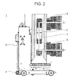
- FIG. 2 illustrates a current flow of a conventional vacuum circuit breaker.
- a current applied from a power supply flows into a load via the upper terminal 5, a vacuum interrupter 7, and the lower terminal 6, sequentially.
- the upper terminal 5 and the lower terminal 6 of the main circuit part 2 are made of copper.
- the cross-sectional area of the upper and lower terminals 5 and 6 becomes larger in proportion thereto.
- the copper has a relatively high weight due to its high density
- the upper and lower terminals 5 and 6 of the large-capacity vacuum circuit breaker are configured as a hollow type so as to have a minimum weight, while maintaining a minimum sectional area for current application.
- Korean Patent No. 10-0950129 (Title : Main Circuit Terminal Assembly of Vacuum Circuit Breaker) may be referred to as a prior art of the present invention.
- an object of the present invention is to provide a terminal structure of a main circuit part of a vacuum circuit breaker, which is capable of efficiently discharging heat generated from the main circuit part of the vacuum circuit breaker, thereby preventing a temperature rise in the main circuit part of the high-pressure vacuum circuit breaker.
- a terminal structure of a main circuit part of a vacuum circuit breaker including a cylindrical terminal having a circular heat fin unit at its inner surface and an air-flow path formed at upper and lower portions thereof in a direction perpendicular to a ground surface; and bar type terminal having a plurality of fin blades at an upper surface, a lower surface and side surfaces thereof.
- the air-flow path may include an upper aperture formed at an upper side of the cylindrical terminal and a lower aperture formed at a lower side of the cylindrical terminal.
- the upper aperture and the lower aperture may be formed to be symmetrical to each other.
- the upper aperture and the lower aperture may be formed to extend toward an inner surface of the cylindrical terminal.
- An outer diameter of the circular heat fin unit may be smaller than an inner diameter of the cylindrical terminal.
- the circular heat fin unit may be located at the air-flow path.
- the circular heat fin unit may be provided in a lengthwise direction of the air-flow path.
- the present invention can have the following advantages. Firstly, as an air-flow path is formed within a closed space of a terminal of a main circuit part for air circulation with outside, a temperature rise in the terminal can be reduced.
- the circular heat fin unit provided on the inner surface of the cylindrical terminal is located at the air-flow path, heat diffusion efficiency can be increased.
- a terminal structure of a main circuit part of a vacuum circuit breaker includes a cylindrical terminal having an air-flow path and a bar type terminal having a plurality of fin blades at its front surface.
- FIG. 4 is a front perspective view of a terminal structure of a main circuit part of a vacuum circuit breaker according to an embodiment of the present invention
- FIG. 5 is a rear perspective view of a terminal structure of a main circuit part of a vacuum circuit breaker according to an embodiment of the present invention
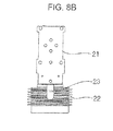
- FIGS. 6A and 6B are a perspective view and a planar view of a terminal structure of a main circuit part of a vacuum circuit breaker according to an embodiment of the present invention, respectively
- FIG. 7 is a perspective view of a terminal structure of a main circuit part of a vacuum circuit breaker from which a heat diffusion fin unit is separated
- FIGS. 8A to 8C are a perspective view, a planar view and a front view illustrating a terminal structure of the present invention.
- FIGS. 4 through 8C a terminal structure of a main circuit part of a vacuum circuit breaker according to an embodiment of the present invention will now be explained in detail.
- a main body 10 is provided.
- a main circuit part 15 of the main body 10 includes an upper terminal 20 and a lower terminal 30 which are provided to protrude outwardly.
- Each of the upper and lower terminals 20 and 30 is provided with a plurality of heat diffusion fins 40 to efficiently discharge heat generated by a large current flowing therethrough.
- a current applied from a power supply flows into the lower terminal 30 through the upper terminal 20 and a vacuum interrupter 41, sequentially. Then, the current is applied to a load.
- a flexible shunt 42 may be provided in order to provide a gap for allowing a flexible movement of a movable unit of the vacuum interrupter 41.
- the main circuit part 15 is generally provided at the main body 10 for three-phases(R-S-T). As the three phases are formed and operated in the same manner, a main circuit part of only a single phase will now be described.
- the upper terminal 20 includes a bar type terminal 21 and a cylindrical terminal 22.
- the bar type terminal 21 is formed in a box type, and coupled to an upper portion of a fixed electrode of the vacuum interrupter 41.
- a plurality of heat fins 40 are provided at an upper surface, a lower surface and side surfaces of the bar type terminal 21 to discharge heat generated while a current flows.
- the bar type terminal 21 and the cylindrical terminal 22 may be coupled to each other by means of a brazing welding.
- the cylindrical terminal 22 is formed in an approximately cup-shape. A part of a closed space inside the cylindrical terminal 22 is open to provide an air-flow path for air circulation with the exterior. As an embodiment of the air- flow path, an upper aperture 23 and a lower aperture 24 are formed at an upper portion and a lower portion of the cylindrical terminal 22, respectively. By virtue of the upper and lower apertures 23 and 24, an air-flow path through which air flows from a lower part of the upper terminal 20 to an upper part of the upper terminal 20, may be formed. And a natural convection of air may occur through the air-flow path.
- the air-flow path may be formed to be perpendicular to a ground surface to thus utilize a natural convection.
- the upper and lower apertures 23 and 24 may be formed symmetrical to each other at the upper and lower portions of the cylindrical terminal 22.
- the upper and lower apertures 23 and 24 may be formed to extend to an inner surface 25 of the cylindrical terminal 22. As the upper and lower apertures 23 and 24 may be formed to extend to the inner surface 25 of the cylindrical terminal 22, an inflow of external air through the lower aperture 24 and a discharge of internal air through the upper aperture 23 may be efficiently performed.
- a circular heat fin unit 50 having a plurality of fin blades at its front surface is coupled to the inner surface 25 of the cylindrical terminal 22.
- a coupling hole 26 may be formed at the inner surface 25.
- the circular heat fin unit 50 may be coupled by a coupling means such as a screw 59.
- an additional means such as a mounting recess may be formed within the inner surface 25 of the cylindrical terminal 22 in order to facilitate fixture of the circular heat fin unit 50.
- the circular heat fin unit 50 can be easily inserted into the cylindrical terminal 22, due to a circular shape thereof.
- An outer diameter of the circular heat fin unit 50 is smaller than an inner diameter of the cylindrical terminal 22.
- a relation between the outer diameter 'D' of the circular heat fin unit 50 and the inner diameter 'd' of the cylindrical terminal 22 may be D ⁇ 4/5d.
- a more precise value may be obtained through hydrodynamics experiments. Under such a configuration, a gap is formed between the upper and lower apertures 23 and 24 and the circular heat fin unit 50, so that air circulation can be smoothly performed.
- the circular heat fin unit 50 may be located at the air-flow path.
- the circular heat fin unit 50 may be exposed to air flowing through the air-flow path, thereby efficiently performing a heat diffusion.
- fin blades of the circular heat fin unit 50 may be provided in a lengthwise direction of the air-flow path to minimize resistance to an air flow.
- the air-flow path and the circular heat fin unit 50 may be provided in the same manner as the upper terminal 20.
- the upper and lower terminal structure of the present invention may easily discharge heat therewithin and reduce temperature rise due to a current flow so that a small and compact sized vacuum circuit breaker may be obtained.
Landscapes
- Engineering & Computer Science (AREA)
- Power Engineering (AREA)
- High-Tension Arc-Extinguishing Switches Without Spraying Means (AREA)
- Trip Switchboards (AREA)
Abstract
Description
- The present invention relates to a main circuit part of a vacuum circuit breaker, and more particularly, to a terminal structure of a main circuit part of a vacuum circuit breaker.
- In general, a vacuum circuit breaker is a circuit breaker installed in a high voltage electric power system to break a circuit to protect the electric power system in the event of a dangerous situation such as a short circuit or an overcurrent, and it is designed by utilizing excellent insulating performance and arc-extinguishing capability in a vacuum state.
- The vacuum circuit breaker is categorized into a drawable type vacuum circuit breaker and a fixed type vacuum circuit breaker. That is, the vacuum circuit breaker is divided into a fixed type circuit breaker which consists only of a main body and is fixed to a switch panel, and a drawable type circuit breaker which is configured to have an outer box called a cradle for facilitating the maintenance and repair of the circuit breaker so that a main body is retracted into or pulled out of the cradle.
-
FIG. 1 illustrates a main body of a drawable type vacuum circuit breaker according to the conventional art. As shown inFIG. 1 , themain body 1 of the vacuum circuit breaker includes amain circuit part 2, amanipulation part 3, and afeeding part 4. Among these parts, themain circuit part 2 is an essential one which is operated to apply or break a current and a voltage in the circuit system, and includes anupper terminal 5 connected to a power supply and alower terminal 6 connected to a load. -
FIG. 2 illustrates a current flow of a conventional vacuum circuit breaker. - Referring to
FIG. 2 , a current applied from a power supply flows into a load via theupper terminal 5, avacuum interrupter 7, and thelower terminal 6, sequentially. - In such a conventional vacuum circuit breaker, the
upper terminal 5 and thelower terminal 6 of themain circuit part 2 are made of copper. As the current carrying capability of the circuit becomes larger, the cross-sectional area of the upper andlower terminals lower terminals lower terminals FIG. 3 , resulting in high-temperature air within the closed spaces A and B. This may cause the temperature of the upper andlower terminals terminals - However, there have been some problems in that as the size of the
terminals - Meanwhile, Korean Patent No.
10-0950129 - Therefore, an object of the present invention is to provide a terminal structure of a main circuit part of a vacuum circuit breaker, which is capable of efficiently discharging heat generated from the main circuit part of the vacuum circuit breaker, thereby preventing a temperature rise in the main circuit part of the high-pressure vacuum circuit breaker.
- To achieve these and other advantages and in accordance with the purpose of this specification, as embodied and broadly described herein, there is provided a terminal structure of a main circuit part of a vacuum circuit breaker, including a cylindrical terminal having a circular heat fin unit at its inner surface and an air-flow path formed at upper and lower portions thereof in a direction perpendicular to a ground surface; and bar type terminal having a plurality of fin blades at an upper surface, a lower surface and side surfaces thereof.
- The air-flow path may include an upper aperture formed at an upper side of the cylindrical terminal and a lower aperture formed at a lower side of the cylindrical terminal.
- The upper aperture and the lower aperture may be formed to be symmetrical to each other.
- The upper aperture and the lower aperture may be formed to extend toward an inner surface of the cylindrical terminal.
- An outer diameter of the circular heat fin unit may be smaller than an inner diameter of the cylindrical terminal.
- The circular heat fin unit may be located at the air-flow path.
- The circular heat fin unit may be provided in a lengthwise direction of the air-flow path.
- The present invention can have the following advantages. Firstly, as an air-flow path is formed within a closed space of a terminal of a main circuit part for air circulation with outside, a temperature rise in the terminal can be reduced.
- Further, the circular heat fin unit provided on the inner surface of the cylindrical terminal is located at the air-flow path, heat diffusion efficiency can be increased.
- Thus, a compact-sized terminal structure of a main circuit part can be implemented.
- The accompanying drawings, which are included to provide a further understanding of the invention and are incorporated in and constitute a part of this specification, illustrate exemplary embodiments and together with the description serve to explain the principles of the invention.
- In the drawings:
-
FIG. 1 illustrates a circuit breaker in accordance with the conventional art; -
FIG. 2 is a view illustrating a current flow in a circuit breaker in accordance with the conventional art; -
FIG. 3 is a side view illustrating an inner state of a terminal structure of a main circuit part shown inFIG. 2 ; -
FIG. 4 is a front perspective view of a terminal structure of a main circuit part of a vacuum circuit breaker according to an embodiment of the present invention; -
FIG. 5 is a rear perspective view of a terminal structure of a main circuit part of a vacuum circuit breaker according to an embodiment of the present invention; -
FIGS. 6A and6B are a perspective view and a planar view of a terminal structure of a main circuit part of a vacuum circuit breaker according to an embodiment of the present invention, respectively; -
FIG. 7 is a perspective view of a terminal structure of a main circuit part of a vacuum circuit breaker from which a heat diffusion fin unit is separated; and -
FIGS. 8A to 8C are a perspective view, a planar view and a front view illustrating a terminal structure of the present invention. - Hereinafter, a preferred embodiment of the present invention will be described in detail with reference to the accompanying drawings.
- A terminal structure of a main circuit part of a vacuum circuit breaker according to an embodiment of the present invention includes a cylindrical terminal having an air-flow path and a bar type terminal having a plurality of fin blades at its front surface.
-
FIG. 4 is a front perspective view of a terminal structure of a main circuit part of a vacuum circuit breaker according to an embodiment of the present invention;FIG. 5 is a rear perspective view of a terminal structure of a main circuit part of a vacuum circuit breaker according to an embodiment of the present invention;FIGS. 6A and6B are a perspective view and a planar view of a terminal structure of a main circuit part of a vacuum circuit breaker according to an embodiment of the present invention, respectively;FIG. 7 is a perspective view of a terminal structure of a main circuit part of a vacuum circuit breaker from which a heat diffusion fin unit is separated; andFIGS. 8A to 8C are a perspective view, a planar view and a front view illustrating a terminal structure of the present invention. - Referring to
FIGS. 4 through 8C , a terminal structure of a main circuit part of a vacuum circuit breaker according to an embodiment of the present invention will now be explained in detail. - As shown in
FIGS. 4 and5 , amain body 10 is provided. Amain circuit part 15 of themain body 10 includes anupper terminal 20 and alower terminal 30 which are provided to protrude outwardly. Each of the upper andlower terminals lower terminal 30 through theupper terminal 20 and avacuum interrupter 41, sequentially. Then, the current is applied to a load. Between thevacuum interrupter 41 and thelower terminal 30, aflexible shunt 42 may be provided in order to provide a gap for allowing a flexible movement of a movable unit of thevacuum interrupter 41. - The
main circuit part 15 is generally provided at themain body 10 for three-phases(R-S-T). As the three phases are formed and operated in the same manner, a main circuit part of only a single phase will now be described. - The
upper terminal 20 includes abar type terminal 21 and acylindrical terminal 22. Thebar type terminal 21 is formed in a box type, and coupled to an upper portion of a fixed electrode of thevacuum interrupter 41. A plurality ofheat fins 40 are provided at an upper surface, a lower surface and side surfaces of thebar type terminal 21 to discharge heat generated while a current flows. Thebar type terminal 21 and thecylindrical terminal 22 may be coupled to each other by means of a brazing welding. - The
cylindrical terminal 22 is formed in an approximately cup-shape. A part of a closed space inside thecylindrical terminal 22 is open to provide an air-flow path for air circulation with the exterior. As an embodiment of the air- flow path, anupper aperture 23 and alower aperture 24 are formed at an upper portion and a lower portion of thecylindrical terminal 22, respectively. By virtue of the upper andlower apertures upper terminal 20 to an upper part of theupper terminal 20, may be formed. And a natural convection of air may occur through the air-flow path. That is, cold air at a lower part of thecylindrical terminal 22 flows into an inner space of thecylindrical terminal 22 through thelower aperture 24, and hot air in the inner space of thecylindrical terminal 22 is discharged out through theupper aperture 23. Under such a configuration, heat within thecylindrical terminal 22 may be discharged out. Since the upper andlower apertures cylindrical terminal 22, respectively, the air-flow path may be formed to be perpendicular to a ground surface to thus utilize a natural convection. - The upper and
lower apertures cylindrical terminal 22. - Further, the upper and
lower apertures inner surface 25 of thecylindrical terminal 22. As the upper andlower apertures inner surface 25 of thecylindrical terminal 22, an inflow of external air through thelower aperture 24 and a discharge of internal air through theupper aperture 23 may be efficiently performed. - A circular
heat fin unit 50 having a plurality of fin blades at its front surface is coupled to theinner surface 25 of thecylindrical terminal 22. To couple the circularheat fin unit 50 to theinner surface 25 of thecylindrical terminal 22, acoupling hole 26 may be formed at theinner surface 25. The circularheat fin unit 50 may be coupled by a coupling means such as ascrew 59. Although not shown in the drawings, an additional means such as a mounting recess may be formed within theinner surface 25 of thecylindrical terminal 22 in order to facilitate fixture of the circularheat fin unit 50. - The circular
heat fin unit 50 can be easily inserted into thecylindrical terminal 22, due to a circular shape thereof. An outer diameter of the circularheat fin unit 50 is smaller than an inner diameter of thecylindrical terminal 22. Assuming that an outer diameter of the circularheat fin unit 50 is 'D' and an inner diameter of thecylindrical terminal 22 is 'd', a relation between the outer diameter 'D' of the circularheat fin unit 50 and the inner diameter 'd' of thecylindrical terminal 22 may be D<4/5d. A more precise value may be obtained through hydrodynamics experiments. Under such a configuration, a gap is formed between the upper andlower apertures heat fin unit 50, so that air circulation can be smoothly performed. - Preferably, the circular
heat fin unit 50 may be located at the air-flow path. The circularheat fin unit 50 may be exposed to air flowing through the air-flow path, thereby efficiently performing a heat diffusion. - Further, fin blades of the circular
heat fin unit 50 may be provided in a lengthwise direction of the air-flow path to minimize resistance to an air flow. - With respect to the
lower terminal 30, the air-flow path and the circularheat fin unit 50 may be provided in the same manner as theupper terminal 20. - Further, as the circular
heat fin unit 50 is mounted within thecylindrical terminal 22, lowering of an insulation efficiency can be prevented. - As described above, the upper and lower terminal structure of the present invention may easily discharge heat therewithin and reduce temperature rise due to a current flow so that a small and compact sized vacuum circuit breaker may be obtained.
- As the present features may be embodied in several forms without departing from the characteristics thereof, it should also be understood that the above-described embodiments are not limited by any of the details of the foregoing description, unless otherwise specified, but rather should be construed broadly within its scope as defined in the appended claims, and therefore all changes and modifications that fall within the metes and bounds of the claims, or equivalents of such metes and bounds are therefore intended to be embraced by the appended claims.
Claims (7)
- A terminal structure of a main circuit part of a vacuum circuit breaker, comprising:a cylindrical terminal 22 having a circular heat fin unit 50 at an inner surface thereof and an air-flow path formed at upper and lower surfaces thereof in a direction perpendicular to a ground surface; anda bar type terminal 21 formed of a box type and having a plurality of heat diffusion fins at an upper surface, a lower surface, and side surfaces thereof.
- The terminal structure of claim 1, wherein the air-flow path includes:an upper aperture 23 formed at an upper side of the cylindrical terminal 22; anda lower aperture 24 formed at a lower side of the cylindrical terminal 22.
- The terminal structure of claim 2, wherein the upper aperture 23 and the lower aperture 24 are formed to be symmetrical to each other.
- The terminal structure of claim 2, wherein the upper aperture 23 and the lower aperture 24 are formed to extend toward the inner surface of the cylindrical terminal 22.
- The terminal structure of claim 1, wherein an outer diameter of the circular heat fin unit 50 is smaller than an inner diameter of the cylindrical terminal 22.
- The terminal structure of claim 1, wherein the circular heat fin unit 50 is located on the air-flow path.
- The terminal structure of claim 1, wherein the circular heat fin unit 50 is provided in a lengthwise direction of the air-flow path.
Applications Claiming Priority (1)
| Application Number | Priority Date | Filing Date | Title |
|---|---|---|---|
| KR1020130160479A KR101545889B1 (en) | 2013-12-20 | 2013-12-20 | Terminal Structure of Main Circuit Part of Vacuum Circuit Breaker |
Publications (2)
| Publication Number | Publication Date |
|---|---|
| EP2887373A1 true EP2887373A1 (en) | 2015-06-24 |
| EP2887373B1 EP2887373B1 (en) | 2016-06-29 |
Family
ID=51726393
Family Applications (1)
| Application Number | Title | Priority Date | Filing Date |
|---|---|---|---|
| EP14188760.4A Not-in-force EP2887373B1 (en) | 2013-12-20 | 2014-10-14 | Terminal structure of main circuit part of vacuum circuit breaker |
Country Status (6)
| Country | Link |
|---|---|
| US (1) | US9418805B2 (en) |
| EP (1) | EP2887373B1 (en) |
| JP (1) | JP5912160B2 (en) |
| KR (1) | KR101545889B1 (en) |
| CN (1) | CN104733220B (en) |
| ES (1) | ES2593488T3 (en) |
Cited By (2)
| Publication number | Priority date | Publication date | Assignee | Title |
|---|---|---|---|---|
| EP3171381B1 (en) * | 2015-11-20 | 2024-09-04 | Siemens Aktiengesellschaft | Contact structure of a circuit breaker |
| EP4542607A1 (en) * | 2023-10-16 | 2025-04-23 | General Electric Technology GmbH | Air cooled disconnector provided with cooling slots |
Families Citing this family (5)
| Publication number | Priority date | Publication date | Assignee | Title |
|---|---|---|---|---|
| KR20180000846U (en) | 2016-09-19 | 2018-03-28 | 현대일렉트릭앤에너지시스템(주) | Switchgear |
| US11688638B2 (en) * | 2017-03-28 | 2023-06-27 | Sri International | Production of very small or thin dies |
| US10270231B2 (en) | 2017-06-20 | 2019-04-23 | Hamilton Sundstrand Corporation | Integrated contactor mounting post |
| CN118231199A (en) * | 2022-12-21 | 2024-06-21 | Abb瑞士股份有限公司 | Circuit breaker and tulip contact for thermal management in electrical equipment |
| KR20250115596A (en) * | 2024-01-24 | 2025-07-31 | 엘에스일렉트릭(주) | Circuit Breaker |
Citations (2)
| Publication number | Priority date | Publication date | Assignee | Title |
|---|---|---|---|---|
| DE20121796U1 (en) * | 2001-12-21 | 2003-05-15 | Siemens AG, 80333 München | Pole mounting holding and contacting breaker of gas-filled power switch, has cooling fins of specified separation and length along gas flow direction |
| KR100950129B1 (en) | 2008-02-05 | 2010-03-30 | 엘에스산전 주식회사 | Main Circuit Terminal Assembly of Vacuum Circuit Breaker |
Family Cites Families (10)
| Publication number | Priority date | Publication date | Assignee | Title |
|---|---|---|---|---|
| US4005297A (en) * | 1972-10-18 | 1977-01-25 | Westinghouse Electric Corporation | Vacuum-type circuit interrupters having heat-dissipating devices associated with the contact structures thereof |
| US5753875A (en) * | 1996-10-15 | 1998-05-19 | Eaton Corporation | Heat sink for contact stems of a vacuum interrupter and a vacuum interrupter therewith |
| JPH10322819A (en) | 1997-05-13 | 1998-12-04 | Toshiba Corp | Main circuit disconnection |
| US5929410A (en) * | 1998-01-26 | 1999-07-27 | Lg Industrial Systems Co., Ltd. | Terminal structure for vacuum circuit breaker |
| JP2004072914A (en) | 2002-08-07 | 2004-03-04 | Mitsubishi Electric Corp | Power circuit breaker |
| JP4606146B2 (en) | 2004-12-09 | 2011-01-05 | 三菱電機株式会社 | Switchgear |
| JP5210582B2 (en) | 2007-09-27 | 2013-06-12 | 株式会社日立製作所 | Vacuum switchgear |
| CN102017039B (en) | 2007-12-07 | 2014-04-02 | Abb技术有限公司 | Heat dissipating means for circuit-breaker and circuit-breaker with such heat dissipating means |
| WO2009079871A1 (en) * | 2007-12-07 | 2009-07-02 | Abb (China) Limited | Circuit breaker with a heat dissipating means |
| JP2009277386A (en) * | 2008-05-12 | 2009-11-26 | Toshiba Corp | Vacuum circuit breaker |
-
2013
- 2013-12-20 KR KR1020130160479A patent/KR101545889B1/en active Active
-
2014
- 2014-09-18 US US14/490,310 patent/US9418805B2/en active Active
- 2014-10-07 JP JP2014206138A patent/JP5912160B2/en not_active Expired - Fee Related
- 2014-10-14 ES ES14188760.4T patent/ES2593488T3/en active Active
- 2014-10-14 EP EP14188760.4A patent/EP2887373B1/en not_active Not-in-force
- 2014-11-28 CN CN201410710253.8A patent/CN104733220B/en active Active
Patent Citations (2)
| Publication number | Priority date | Publication date | Assignee | Title |
|---|---|---|---|---|
| DE20121796U1 (en) * | 2001-12-21 | 2003-05-15 | Siemens AG, 80333 München | Pole mounting holding and contacting breaker of gas-filled power switch, has cooling fins of specified separation and length along gas flow direction |
| KR100950129B1 (en) | 2008-02-05 | 2010-03-30 | 엘에스산전 주식회사 | Main Circuit Terminal Assembly of Vacuum Circuit Breaker |
Cited By (2)
| Publication number | Priority date | Publication date | Assignee | Title |
|---|---|---|---|---|
| EP3171381B1 (en) * | 2015-11-20 | 2024-09-04 | Siemens Aktiengesellschaft | Contact structure of a circuit breaker |
| EP4542607A1 (en) * | 2023-10-16 | 2025-04-23 | General Electric Technology GmbH | Air cooled disconnector provided with cooling slots |
Also Published As
| Publication number | Publication date |
|---|---|
| KR101545889B1 (en) | 2015-08-20 |
| JP2015122304A (en) | 2015-07-02 |
| CN104733220B (en) | 2017-07-18 |
| US9418805B2 (en) | 2016-08-16 |
| ES2593488T3 (en) | 2016-12-09 |
| CN104733220A (en) | 2015-06-24 |
| EP2887373B1 (en) | 2016-06-29 |
| US20150179375A1 (en) | 2015-06-25 |
| JP5912160B2 (en) | 2016-04-27 |
| KR20150072860A (en) | 2015-06-30 |
Similar Documents
| Publication | Publication Date | Title |
|---|---|---|
| EP2887373B1 (en) | Terminal structure of main circuit part of vacuum circuit breaker | |
| US6762389B1 (en) | Gas discharge filter for electrical switching apparatus | |
| EP3158570B1 (en) | Electrical switching apparatus, and jumper and associated method therefor | |
| US10354792B2 (en) | Transformer structure | |
| KR101748311B1 (en) | Gas cooler for a medium voltage switchgear assembly | |
| CN202696036U (en) | Contact box device of switch device | |
| JP6680228B2 (en) | DC circuit breaker | |
| US7336477B2 (en) | Electrical switching apparatus and heat sink therefor | |
| CN102017039B (en) | Heat dissipating means for circuit-breaker and circuit-breaker with such heat dissipating means | |
| CN212874379U (en) | Terminal clamp covering device for low voltage circuit breaker and corresponding low voltage circuit breaker | |
| EP2306482B1 (en) | Main circuit terminal assembly for vacuum circuit breaker | |
| CN102510203B (en) | Converter device of MW (Megawatt) excitation wind power unit | |
| CN217740376U (en) | Connecting bar for heat dissipation of molded case circuit breaker and heat dissipation structure of molded case circuit breaker | |
| CN217405317U (en) | Solid-sealed polar pole cooled by high-pressure air cooling | |
| CN120226112A (en) | Thermal management device for circuit breaker | |
| CN105762028B (en) | Contact arm of a circuit breaker and method for manufacturing the contact arm | |
| CN116798791A (en) | Connection strip for heat dissipation of molded case circuit breaker and heat dissipation structure of the molded case circuit breaker | |
| CN222320138U (en) | Fixed breaker | |
| JP6212816B2 (en) | Distribution board | |
| EP2942849B1 (en) | Circuit breaker box, and switching device for electric power | |
| US11909181B2 (en) | Compartment for a medium voltage air or gas insulated switchgear | |
| KR102851382B1 (en) | Circuit connecting device of low voltage dc circuit breaker, and low voltage dc circuit breaker including the same | |
| CN212625422U (en) | Plastic shell type circuit breaker | |
| JP2009195020A (en) | Distribution board | |
| BR112022013999B1 (en) | FUSION DEVICE |
Legal Events
| Date | Code | Title | Description |
|---|---|---|---|
| PUAI | Public reference made under article 153(3) epc to a published international application that has entered the european phase |
Free format text: ORIGINAL CODE: 0009012 |
|
| 17P | Request for examination filed |
Effective date: 20141014 |
|
| AK | Designated contracting states |
Kind code of ref document: A1 Designated state(s): AL AT BE BG CH CY CZ DE DK EE ES FI FR GB GR HR HU IE IS IT LI LT LU LV MC MK MT NL NO PL PT RO RS SE SI SK SM TR |
|
| AX | Request for extension of the european patent |
Extension state: BA ME |
|
| R17P | Request for examination filed (corrected) |
Effective date: 20150611 |
|
| RBV | Designated contracting states (corrected) |
Designated state(s): AL AT BE BG CH CY CZ DE DK EE ES FI FR GB GR HR HU IE IS IT LI LT LU LV MC MK MT NL NO PL PT RO RS SE SI SK SM TR |
|
| GRAP | Despatch of communication of intention to grant a patent |
Free format text: ORIGINAL CODE: EPIDOSNIGR1 |
|
| RIC1 | Information provided on ipc code assigned before grant |
Ipc: H01H 33/66 20060101AFI20150903BHEP Ipc: H02B 11/12 20060101ALN20150903BHEP |
|
| INTG | Intention to grant announced |
Effective date: 20150929 |
|
| INTG | Intention to grant announced |
Effective date: 20160108 |
|
| RIC1 | Information provided on ipc code assigned before grant |
Ipc: H02B 11/12 20060101ALN20151221BHEP Ipc: H01H 33/66 20060101AFI20151221BHEP |
|
| GRAS | Grant fee paid |
Free format text: ORIGINAL CODE: EPIDOSNIGR3 |
|
| GRAA | (expected) grant |
Free format text: ORIGINAL CODE: 0009210 |
|
| AK | Designated contracting states |
Kind code of ref document: B1 Designated state(s): AL AT BE BG CH CY CZ DE DK EE ES FI FR GB GR HR HU IE IS IT LI LT LU LV MC MK MT NL NO PL PT RO RS SE SI SK SM TR |
|
| REG | Reference to a national code |
Ref country code: GB Ref legal event code: FG4D |
|
| REG | Reference to a national code |
Ref country code: CH Ref legal event code: EP |
|
| REG | Reference to a national code |
Ref country code: AT Ref legal event code: REF Ref document number: 809682 Country of ref document: AT Kind code of ref document: T Effective date: 20160715 |
|
| REG | Reference to a national code |
Ref country code: IE Ref legal event code: FG4D |
|
| REG | Reference to a national code |
Ref country code: DE Ref legal event code: R096 Ref document number: 602014002477 Country of ref document: DE |
|
| REG | Reference to a national code |
Ref country code: FR Ref legal event code: PLFP Year of fee payment: 3 |
|
| REG | Reference to a national code |
Ref country code: LT Ref legal event code: MG4D |
|
| PG25 | Lapsed in a contracting state [announced via postgrant information from national office to epo] |
Ref country code: NO Free format text: LAPSE BECAUSE OF FAILURE TO SUBMIT A TRANSLATION OF THE DESCRIPTION OR TO PAY THE FEE WITHIN THE PRESCRIBED TIME-LIMIT Effective date: 20160929 Ref country code: FI Free format text: LAPSE BECAUSE OF FAILURE TO SUBMIT A TRANSLATION OF THE DESCRIPTION OR TO PAY THE FEE WITHIN THE PRESCRIBED TIME-LIMIT Effective date: 20160629 Ref country code: LT Free format text: LAPSE BECAUSE OF FAILURE TO SUBMIT A TRANSLATION OF THE DESCRIPTION OR TO PAY THE FEE WITHIN THE PRESCRIBED TIME-LIMIT Effective date: 20160629 |
|
| REG | Reference to a national code |
Ref country code: NL Ref legal event code: MP Effective date: 20160629 |
|
| PG25 | Lapsed in a contracting state [announced via postgrant information from national office to epo] |
Ref country code: LV Free format text: LAPSE BECAUSE OF FAILURE TO SUBMIT A TRANSLATION OF THE DESCRIPTION OR TO PAY THE FEE WITHIN THE PRESCRIBED TIME-LIMIT Effective date: 20160629 Ref country code: RS Free format text: LAPSE BECAUSE OF FAILURE TO SUBMIT A TRANSLATION OF THE DESCRIPTION OR TO PAY THE FEE WITHIN THE PRESCRIBED TIME-LIMIT Effective date: 20160629 Ref country code: NL Free format text: LAPSE BECAUSE OF FAILURE TO SUBMIT A TRANSLATION OF THE DESCRIPTION OR TO PAY THE FEE WITHIN THE PRESCRIBED TIME-LIMIT Effective date: 20160629 Ref country code: SE Free format text: LAPSE BECAUSE OF FAILURE TO SUBMIT A TRANSLATION OF THE DESCRIPTION OR TO PAY THE FEE WITHIN THE PRESCRIBED TIME-LIMIT Effective date: 20160629 Ref country code: GR Free format text: LAPSE BECAUSE OF FAILURE TO SUBMIT A TRANSLATION OF THE DESCRIPTION OR TO PAY THE FEE WITHIN THE PRESCRIBED TIME-LIMIT Effective date: 20160930 Ref country code: HR Free format text: LAPSE BECAUSE OF FAILURE TO SUBMIT A TRANSLATION OF THE DESCRIPTION OR TO PAY THE FEE WITHIN THE PRESCRIBED TIME-LIMIT Effective date: 20160629 |
|
| REG | Reference to a national code |
Ref country code: ES Ref legal event code: FG2A Ref document number: 2593488 Country of ref document: ES Kind code of ref document: T3 Effective date: 20161209 |
|
| REG | Reference to a national code |
Ref country code: AT Ref legal event code: MK05 Ref document number: 809682 Country of ref document: AT Kind code of ref document: T Effective date: 20160629 |
|
| PG25 | Lapsed in a contracting state [announced via postgrant information from national office to epo] |
Ref country code: EE Free format text: LAPSE BECAUSE OF FAILURE TO SUBMIT A TRANSLATION OF THE DESCRIPTION OR TO PAY THE FEE WITHIN THE PRESCRIBED TIME-LIMIT Effective date: 20160629 Ref country code: IS Free format text: LAPSE BECAUSE OF FAILURE TO SUBMIT A TRANSLATION OF THE DESCRIPTION OR TO PAY THE FEE WITHIN THE PRESCRIBED TIME-LIMIT Effective date: 20161029 Ref country code: SK Free format text: LAPSE BECAUSE OF FAILURE TO SUBMIT A TRANSLATION OF THE DESCRIPTION OR TO PAY THE FEE WITHIN THE PRESCRIBED TIME-LIMIT Effective date: 20160629 Ref country code: CZ Free format text: LAPSE BECAUSE OF FAILURE TO SUBMIT A TRANSLATION OF THE DESCRIPTION OR TO PAY THE FEE WITHIN THE PRESCRIBED TIME-LIMIT Effective date: 20160629 Ref country code: RO Free format text: LAPSE BECAUSE OF FAILURE TO SUBMIT A TRANSLATION OF THE DESCRIPTION OR TO PAY THE FEE WITHIN THE PRESCRIBED TIME-LIMIT Effective date: 20160629 |
|
| PG25 | Lapsed in a contracting state [announced via postgrant information from national office to epo] |
Ref country code: AT Free format text: LAPSE BECAUSE OF FAILURE TO SUBMIT A TRANSLATION OF THE DESCRIPTION OR TO PAY THE FEE WITHIN THE PRESCRIBED TIME-LIMIT Effective date: 20160629 Ref country code: SM Free format text: LAPSE BECAUSE OF FAILURE TO SUBMIT A TRANSLATION OF THE DESCRIPTION OR TO PAY THE FEE WITHIN THE PRESCRIBED TIME-LIMIT Effective date: 20160629 Ref country code: PT Free format text: LAPSE BECAUSE OF FAILURE TO SUBMIT A TRANSLATION OF THE DESCRIPTION OR TO PAY THE FEE WITHIN THE PRESCRIBED TIME-LIMIT Effective date: 20161031 Ref country code: BE Free format text: LAPSE BECAUSE OF NON-PAYMENT OF DUE FEES Effective date: 20160629 Ref country code: PL Free format text: LAPSE BECAUSE OF FAILURE TO SUBMIT A TRANSLATION OF THE DESCRIPTION OR TO PAY THE FEE WITHIN THE PRESCRIBED TIME-LIMIT Effective date: 20160629 |
|
| REG | Reference to a national code |
Ref country code: DE Ref legal event code: R097 Ref document number: 602014002477 Country of ref document: DE |
|
| PG25 | Lapsed in a contracting state [announced via postgrant information from national office to epo] |
Ref country code: DK Free format text: LAPSE BECAUSE OF FAILURE TO SUBMIT A TRANSLATION OF THE DESCRIPTION OR TO PAY THE FEE WITHIN THE PRESCRIBED TIME-LIMIT Effective date: 20160629 |
|
| 26N | No opposition filed |
Effective date: 20170330 |
|
| PLBE | No opposition filed within time limit |
Free format text: ORIGINAL CODE: 0009261 |
|
| STAA | Information on the status of an ep patent application or granted ep patent |
Free format text: STATUS: NO OPPOSITION FILED WITHIN TIME LIMIT |
|
| REG | Reference to a national code |
Ref country code: IE Ref legal event code: MM4A |
|
| PG25 | Lapsed in a contracting state [announced via postgrant information from national office to epo] |
Ref country code: SI Free format text: LAPSE BECAUSE OF FAILURE TO SUBMIT A TRANSLATION OF THE DESCRIPTION OR TO PAY THE FEE WITHIN THE PRESCRIBED TIME-LIMIT Effective date: 20160629 Ref country code: BG Free format text: LAPSE BECAUSE OF FAILURE TO SUBMIT A TRANSLATION OF THE DESCRIPTION OR TO PAY THE FEE WITHIN THE PRESCRIBED TIME-LIMIT Effective date: 20160929 Ref country code: LU Free format text: LAPSE BECAUSE OF NON-PAYMENT OF DUE FEES Effective date: 20161014 |
|
| REG | Reference to a national code |
Ref country code: FR Ref legal event code: PLFP Year of fee payment: 4 |
|
| PG25 | Lapsed in a contracting state [announced via postgrant information from national office to epo] |
Ref country code: IE Free format text: LAPSE BECAUSE OF NON-PAYMENT OF DUE FEES Effective date: 20161014 |
|
| PG25 | Lapsed in a contracting state [announced via postgrant information from national office to epo] |
Ref country code: HU Free format text: LAPSE BECAUSE OF FAILURE TO SUBMIT A TRANSLATION OF THE DESCRIPTION OR TO PAY THE FEE WITHIN THE PRESCRIBED TIME-LIMIT; INVALID AB INITIO Effective date: 20141014 |
|
| REG | Reference to a national code |
Ref country code: CH Ref legal event code: PL |
|
| PG25 | Lapsed in a contracting state [announced via postgrant information from national office to epo] |
Ref country code: CY Free format text: LAPSE BECAUSE OF FAILURE TO SUBMIT A TRANSLATION OF THE DESCRIPTION OR TO PAY THE FEE WITHIN THE PRESCRIBED TIME-LIMIT Effective date: 20160629 Ref country code: MK Free format text: LAPSE BECAUSE OF FAILURE TO SUBMIT A TRANSLATION OF THE DESCRIPTION OR TO PAY THE FEE WITHIN THE PRESCRIBED TIME-LIMIT Effective date: 20160629 Ref country code: MT Free format text: LAPSE BECAUSE OF NON-PAYMENT OF DUE FEES Effective date: 20161031 Ref country code: MC Free format text: LAPSE BECAUSE OF FAILURE TO SUBMIT A TRANSLATION OF THE DESCRIPTION OR TO PAY THE FEE WITHIN THE PRESCRIBED TIME-LIMIT Effective date: 20160629 |
|
| PG25 | Lapsed in a contracting state [announced via postgrant information from national office to epo] |
Ref country code: LI Free format text: LAPSE BECAUSE OF NON-PAYMENT OF DUE FEES Effective date: 20171031 Ref country code: CH Free format text: LAPSE BECAUSE OF NON-PAYMENT OF DUE FEES Effective date: 20171031 |
|
| REG | Reference to a national code |
Ref country code: FR Ref legal event code: PLFP Year of fee payment: 5 |
|
| PG25 | Lapsed in a contracting state [announced via postgrant information from national office to epo] |
Ref country code: TR Free format text: LAPSE BECAUSE OF FAILURE TO SUBMIT A TRANSLATION OF THE DESCRIPTION OR TO PAY THE FEE WITHIN THE PRESCRIBED TIME-LIMIT Effective date: 20160629 Ref country code: AL Free format text: LAPSE BECAUSE OF FAILURE TO SUBMIT A TRANSLATION OF THE DESCRIPTION OR TO PAY THE FEE WITHIN THE PRESCRIBED TIME-LIMIT Effective date: 20160629 |
|
| PGFP | Annual fee paid to national office [announced via postgrant information from national office to epo] |
Ref country code: IT Payment date: 20220906 Year of fee payment: 9 Ref country code: GB Payment date: 20220905 Year of fee payment: 9 |
|
| PGFP | Annual fee paid to national office [announced via postgrant information from national office to epo] |
Ref country code: FR Payment date: 20220905 Year of fee payment: 9 |
|
| PGFP | Annual fee paid to national office [announced via postgrant information from national office to epo] |
Ref country code: ES Payment date: 20221114 Year of fee payment: 9 Ref country code: DE Payment date: 20220603 Year of fee payment: 9 |
|
| REG | Reference to a national code |
Ref country code: DE Ref legal event code: R119 Ref document number: 602014002477 Country of ref document: DE |
|
| GBPC | Gb: european patent ceased through non-payment of renewal fee |
Effective date: 20231014 |
|
| PG25 | Lapsed in a contracting state [announced via postgrant information from national office to epo] |
Ref country code: GB Free format text: LAPSE BECAUSE OF NON-PAYMENT OF DUE FEES Effective date: 20231014 |
|
| PG25 | Lapsed in a contracting state [announced via postgrant information from national office to epo] |
Ref country code: GB Free format text: LAPSE BECAUSE OF NON-PAYMENT OF DUE FEES Effective date: 20231014 Ref country code: FR Free format text: LAPSE BECAUSE OF NON-PAYMENT OF DUE FEES Effective date: 20231031 Ref country code: DE Free format text: LAPSE BECAUSE OF NON-PAYMENT OF DUE FEES Effective date: 20240501 |
|
| REG | Reference to a national code |
Ref country code: ES Ref legal event code: FD2A Effective date: 20241202 |
|
| PG25 | Lapsed in a contracting state [announced via postgrant information from national office to epo] |
Ref country code: IT Free format text: LAPSE BECAUSE OF NON-PAYMENT OF DUE FEES Effective date: 20231014 |
|
| PG25 | Lapsed in a contracting state [announced via postgrant information from national office to epo] |
Ref country code: IT Free format text: LAPSE BECAUSE OF NON-PAYMENT OF DUE FEES Effective date: 20231014 |
|
| PG25 | Lapsed in a contracting state [announced via postgrant information from national office to epo] |
Ref country code: ES Free format text: LAPSE BECAUSE OF NON-PAYMENT OF DUE FEES Effective date: 20231015 |
|
| PG25 | Lapsed in a contracting state [announced via postgrant information from national office to epo] |
Ref country code: ES Free format text: LAPSE BECAUSE OF NON-PAYMENT OF DUE FEES Effective date: 20231015 |