EP2887196B1 - A computer-implemented method for configuring a tool with at least one pointing element on a screen - Google Patents
A computer-implemented method for configuring a tool with at least one pointing element on a screen Download PDFInfo
- Publication number
- EP2887196B1 EP2887196B1 EP13306824.7A EP13306824A EP2887196B1 EP 2887196 B1 EP2887196 B1 EP 2887196B1 EP 13306824 A EP13306824 A EP 13306824A EP 2887196 B1 EP2887196 B1 EP 2887196B1
- Authority
- EP
- European Patent Office
- Prior art keywords
- computer
- tool
- pointing element
- parameter
- screen
- Prior art date
- Legal status (The legal status is an assumption and is not a legal conclusion. Google has not performed a legal analysis and makes no representation as to the accuracy of the status listed.)
- Active
Links
- 238000000034 method Methods 0.000 title claims description 30
- 238000004590 computer program Methods 0.000 claims description 7
- 230000003213 activating effect Effects 0.000 claims description 3
- 238000012360 testing method Methods 0.000 description 13
- 230000000644 propagated effect Effects 0.000 description 12
- 230000009471 action Effects 0.000 description 5
- 230000004913 activation Effects 0.000 description 5
- 238000012545 processing Methods 0.000 description 4
- 238000004891 communication Methods 0.000 description 3
- 230000008859 change Effects 0.000 description 2
- 238000010586 diagram Methods 0.000 description 2
- 238000005516 engineering process Methods 0.000 description 2
- 238000001125 extrusion Methods 0.000 description 2
- 238000012546 transfer Methods 0.000 description 2
- 230000001052 transient effect Effects 0.000 description 2
- 239000008186 active pharmaceutical agent Substances 0.000 description 1
- 230000007423 decrease Effects 0.000 description 1
- 230000000694 effects Effects 0.000 description 1
- 239000003973 paint Substances 0.000 description 1
- 230000008569 process Effects 0.000 description 1
- 230000009466 transformation Effects 0.000 description 1
- 230000007704 transition Effects 0.000 description 1
Images


Classifications
-
- G—PHYSICS
- G06—COMPUTING; CALCULATING OR COUNTING
- G06F—ELECTRIC DIGITAL DATA PROCESSING
- G06F3/00—Input arrangements for transferring data to be processed into a form capable of being handled by the computer; Output arrangements for transferring data from processing unit to output unit, e.g. interface arrangements
- G06F3/01—Input arrangements or combined input and output arrangements for interaction between user and computer
- G06F3/048—Interaction techniques based on graphical user interfaces [GUI]
- G06F3/0487—Interaction techniques based on graphical user interfaces [GUI] using specific features provided by the input device, e.g. functions controlled by the rotation of a mouse with dual sensing arrangements, or of the nature of the input device, e.g. tap gestures based on pressure sensed by a digitiser
- G06F3/0488—Interaction techniques based on graphical user interfaces [GUI] using specific features provided by the input device, e.g. functions controlled by the rotation of a mouse with dual sensing arrangements, or of the nature of the input device, e.g. tap gestures based on pressure sensed by a digitiser using a touch-screen or digitiser, e.g. input of commands through traced gestures
- G06F3/04883—Interaction techniques based on graphical user interfaces [GUI] using specific features provided by the input device, e.g. functions controlled by the rotation of a mouse with dual sensing arrangements, or of the nature of the input device, e.g. tap gestures based on pressure sensed by a digitiser using a touch-screen or digitiser, e.g. input of commands through traced gestures for inputting data by handwriting, e.g. gesture or text
-
- G—PHYSICS
- G06—COMPUTING; CALCULATING OR COUNTING
- G06F—ELECTRIC DIGITAL DATA PROCESSING
- G06F3/00—Input arrangements for transferring data to be processed into a form capable of being handled by the computer; Output arrangements for transferring data from processing unit to output unit, e.g. interface arrangements
- G06F3/01—Input arrangements or combined input and output arrangements for interaction between user and computer
- G06F3/048—Interaction techniques based on graphical user interfaces [GUI]
- G06F3/0484—Interaction techniques based on graphical user interfaces [GUI] for the control of specific functions or operations, e.g. selecting or manipulating an object, an image or a displayed text element, setting a parameter value or selecting a range
- G06F3/04847—Interaction techniques to control parameter settings, e.g. interaction with sliders or dials
Definitions
- the invention relates to the field of computers programs and systems, and more specifically to the field of computer-implemented method for configuring a tool with at least one pointing element on a screen.
- the present invention can belong to any field of technology using configurable tools.
- the invention can belong to any field of technology using (virtual) buttons to activate tools.
- the present invention can be included in CAD products.
- drawing software have different virtual pencils (pens, pencils, brushes, primitive objects, paint).
- CAD software have some authoring tools (primitive creation, transformation, extrusion). All these tools have default parameters that the user is able to modify as color or size of a pencil, depth of an extrusion, type of primitive...
- these customizable parameters can be accessed thanks to a separated panel containing buttons and sliders, or thanks to a contextual menu that appears at click or hold action on the screen, or thanks to a contextual menu that appears after an action on the button.
- click can be considered as a mouse click or a hold action on the screen with another pointing element, as a pen or a finger.
- a hold action can be a quick hold equivalent to a mouse click.
- the background art have some drawbacks, as the number of clicks to launch a tool and customize the parameters, as illustrated in the following table : Nb Parameters 1 5 10 Separated Panel 4 clicks 9 clicks 14 clicks Contextual menu on screen 4 clicks 9 clicks 14 clicks Contextual menu on button 3 clicks 8 clicks 13 clicks
- EP 0 342 838 A2 discloses a concept for selecting two items (e.g. color and saturation) with one user input action.
- US 5 280 275 discloses a graphical user interface for conveying scalar control information.
- a goal of the invention is to provide a computer-implemented method and a system to overcome the above mentioned problems.
- a computer-implemented method for configuring a tool with at least one pointing element on a screen comprising the steps of :
- Such a method allows the user to launch a tool and customize the corresponding parameters with only one click, i.e without lifting the pointing element.
- the idea is to make a gesture on the button in order to, without lifting or releasing the pointing element : launching the tool, accessing the parameters/options, and modifying these parameters.
- a pointing element is a mouse, or a pen or a finger in case of touchscreen.
- said first and second directions are orthogonal, and for example said first direction is vertical and said second direction is horizontal, or conversely.
- orthogonal directions and for example vertical and horizontal directions, is easier for the user. Indeed, it is natural to move a slider horizontally, and, in addition, horizontal and vertical directions are "canonical" directions, thus the gesture is easy to learn and master (as opposed to a smaller angle between the two directions which can cause more handling errors).
- said pointing element is a mouse, a pen, or a finger.
- the screen can be a touch screen or a multi-touch screen.
- said parameter can be thickness, opacity, hardness, or intensity of a color.
- Said parameter can be a parameter with a continue intensity value, or, alternatively a parameter is a parameter with a discrete intensity value.
- the selection and customization of the parameter is displayed above the pointing element.
- the tool can be automatically activated at the end of configuring.
- a computer-readable medium having computer-executable instructions to perform the method for configuring a tool with at least one pointing element on a screen as described above.
- a computer program product stored on a computer readable medium, for displaying a three-dimensional modeled assembly in a scene, comprising code means for causing the system to take the steps of the method for configuring a tool with at least one pointing element on a screen as described above.
- an apparatus for designing a three-dimensional modeled object comprising means for implementing the steps of the method for configuring a tool with at least one pointing element on a screen as described above.
- the present invention allows to configure a tool with only one click (or hold equivalent to a click), whatever could be the number of parameter of the tool he customizes.
- the expression pointing element can represent all means adapted to manage a pointing on the screen, as a mouse, or, in case of touchscreen, also a pen, or a finger.
- the method comprises the following steps, as illustrated on figure 1 :
- the first click or hold with the pointing element activates the concerned tool, as illustrated on figure 2 , with the activation of the tool representing a pen.
- the first direction is vertical (for selecting a customizable parameter of the list of customizable parameters of the tool) and the second direction is horizontal (for customizing a selected parameter of the list), because this is more intuitive and practical for the user.
- a drag of the pointing element that deviates of first and second directions can be still recognized as a drag along one of these directions, once the configuration of a tool has begun.
- two straight lines can separate portions of plan wherein dragging of the pointing element are recognized as a corresponding of these two directions.
- a percentage difference of direction of dragging of the pointing element can be taken into account around the two directions.
- an indicator using differences of successive positions with these two directions during a drag can be taken into account.
- the list of parameters for this tool can be, for example, for the line drawn by the pen tool, can comprise, for example, the following parameters: thickness, hardness, and opacity.
- the user drags the pointing element horizontally, it changes the first parameter of the list of parameters of the tool, which can be the most important, for example the thickness for the pen tool, as illustrated on figures 3 and 4 .
- dragging the pointing element (represented by a hand) on the right increases the value of the parameter in customization
- dragging the pointing element on the left decreases the value of the parameter in customization.
- the focus changes on the next parameter of the list, and when he drags down the pointing element, the focus changes on the previous parameter of the list.
- a circle represents the activation of the tool, by an initial press of the pointing element (a press of a button of the mouse, or a press or hold of the representation of the tool on the touchscreen).
- the first parameter of the list of customizable parameters of the selected tool which can be the main parameter of the tool, in this case the pen tool corresponding to the line drawing tool, is selected by default.
- thickness of a line is considered as the main parameter of the pen tool.
- a first horizontal drag on the right allows to increase the thickness of the line, until the thickness desired by the user is reached.
- an up vertical drag allows to change the selection of the customizable parameter in the list of customizable parameters of the tool, in the present case, the second parameter of the list, which can be, in the present case, opacity of a line (the opposite of transparency).
- This second customizable parameter is then customized with an horizontal drag on the right, as illustrated on figure 14 , to increase the opacity of a line.
- a down vertical drag as represented on figure 15 , allows to change the selection of the customizable parameter, in the present case coming back to the first parameter of the list (line thickness) to modify it.
- an up vertical drag as represented on figure 17 , allows to come back to the second customizable parameter of the list, and by continuing the up vertical drag, as represented on figure 18 , to select the third parameter of the list, for example in the present case the hardness of the line.
- Hardness of a line represent the transition of opacity between the middle of line and the edge of line.
- the third parameter of the list is increased by an horizontal drag on the right.
- Figure 20 schematically represents a method according to an aspect of the invention.
- the tool After an activation of the tool, by a press on a button of the mouse or a hold of the representation of the tool, the tool is launched or activated 190. If the button of the mouse is released without any dragging in any direction, or if the pen or finger stops the hold on the touchscreen, the user makes a release of the pointing element, thus the configuration of the tool is kept unchanged 191.
- the configuration of the tool thus begins with the activation of the tool by a press on a button of the mouse or a hold of the representation of the tool with a finger or a pen, i.e. with any pointing element, and stops with the release of the pointing element, or, in other words at the end of the single gesture.
- a test 192 is performed to check if the drag is mainly horizontal, and if the test 192 is positive, the first parameter of the list which is the main parameter, as in the present example the thickness of the line of the line tool, or the current parameter, is modified 193 according to the horizontal drag.
- a test 194 is effected for testing if the pointing element is released. If the test 194 is positive the configuration of the tool is left 191, and if the test 194 is negative the method returns to the test 192.
- test 192 If the test 192 is negative, then a test 195 is made for testing if the drag is mainly up, and if the test 195 is positive, the method activates the above 196 parameter in the list, and if the test 195 is negative, the method activates 197 the below parameter in the list. After the corresponding activation 196 or 197, the method returns to the test 194.
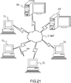
- Figure 21 illustrates a computer network or similar digital processing environment in which the present invention may be implemented.
- Client computer(s)/devices CL and server computer(s) SV provide processing, storage, and input/output devices executing application programs and the like.
- Client computer(s)/devices CL can also be linked through communications network CNET to other computing devices, including other client devices/processes CL and server computer(s) SV.
- Communications network 70 can be part of a remote access network, a global network (e.g., the Internet), a worldwide collection of computers, Local area or Wide area networks, and gateways that currently use respective protocols (TCP/IP, Bluetooth, etc.) to communicate with one another.
- Other electronic device/computer network architectures are suitable.
- FIG 22 is a diagram of the internal structure of a computer (e.g., client processor/device CL or server computers SV) in the computer system of figure 21 .
- Each computer CL, SV contains system bus SB, where a bus is a set of hardware lines used for data transfer among the components of a computer or processing system.
- Bus SB is essentially a shared conduit that connects different elements of a computer system (e.g., processor, disk storage, memory, input/output ports, network ports, etc...) that enables the transfer of information between the elements.
- I/O device interface DI for connecting various input and output devices (e.g., keyboard, mouse, displays, printers, speakers, etc.) to the computer CL, SV.
- Network interface NI allows the computer to connect to various other devices attached to a network (e.g., network CNET of figure 21 ).
- Memory MEM provides volatile storage for computer software instructions SI and data CPP used to implement an embodiment of the present invention (e.g., a first path builder PB, means CM for computing a second path, an updater UD implementing the method discussed in Figs 1 to 20 , and supporting code detailed above).
- SI and data CPP used to implement an embodiment of the present invention (e.g., a first path builder PB, means CM for computing a second path, an updater UD implementing the method discussed in Figs 1 to 20 , and supporting code detailed above).
- Disk storage DS provides non-volatile storage for computer software instructions SI and data DAT used to implement an embodiment of the present invention.
- Central processor unit CPU is also attached to system bus SB and provides for the execution of computer instructions.
- the processor routines SI and data DAT are a computer program product (generally referenced CPP), including a computer readable medium (e.g., a removable storage medium such as one or more DVD-ROM's, CD-ROM's, diskettes, tapes, etc%) that provides at least a portion of the software instructions for the invention system.
- Computer program product CPP can be installed by any suitable software installation procedure, as is well known in the art.
- the software instructions may also be downloaded over a cable, communication and/or wireless connection.
- the invention programs are a computer program propagated signal product SP embodied on a propagated signal on a propagation medium (e.g., a radio wave, an infrared wave, a laser wave, a sound wave, or an electrical wave propagated over a global network such as the Internet, or other network(s)).
- a propagation medium e.g., a radio wave, an infrared wave, a laser wave, a sound wave, or an electrical wave propagated over a global network such as the Internet, or other network(s).
- Such carrier medium or signals provide at least a portion of the software instructions for the present invention routines/program CPP.
- the propagated signal is an analog carrier wave or digital signal carried on the propagated medium.
- the propagated signal may be a digitized signal propagated over a global network (e.g., the Internet), a telecommunications network, or other network.
- the propagated signal is a signal that is transmitted over the propagation medium over a period of time, such as the instructions for a software application sent in packets over a network over a period of milliseconds, seconds, minutes, or longer.
- the computer readable medium of computer program product CPP is a propagation medium that the computer system CL may receive and read, such as by receiving the propagation medium and identifying a propagated signal embodied in the propagation medium, as described above for computer program propagated signal product.
- carrier medium or transient carrier encompasses the foregoing transient signals, propagated signals, propagated medium, storage medium and the like.
Description
- The invention relates to the field of computers programs and systems, and more specifically to the field of computer-implemented method for configuring a tool with at least one pointing element on a screen.
- The present invention can belong to any field of technology using configurable tools.
- The invention can belong to any field of technology using (virtual) buttons to activate tools. For example, the present invention can be included in CAD products.
- Most of software comprise a set of tools. For example, drawing software have different virtual pencils (pens, pencils, brushes, primitive objects, paint...), CAD software have some authoring tools (primitive creation, transformation, extrusion...). All these tools have default parameters that the user is able to modify as color or size of a pencil, depth of an extrusion, type of primitive...
- Often, these customizable parameters can be accessed thanks to a separated panel containing buttons and sliders, or thanks to a contextual menu that appears at click or hold action on the screen, or thanks to a contextual menu that appears after an action on the button.
- In the following the term click can be considered as a mouse click or a hold action on the screen with another pointing element, as a pen or a finger. A hold action can be a quick hold equivalent to a mouse click.
- The background art have some drawbacks, as the number of clicks to launch a tool and customize the parameters, as illustrated in the following table :
Nb Parameters 1 5 10 Separated Panel 4 clicks 9 clicks 14 clicks Contextual menu on screen 4 clicks 9 clicks 14 clicks Contextual menu on button 3 clicks 8 clicks 13 clicks - The cases "separated panel" and "contextual menu on screen" need 1 click to launch the command, 1 click to access the parameters, 1 click by parameter and 1 click to respectively close the panel or menu. The case "contextual menu on button" needs 1 click to launch and access the parameters, 1 click by parameter and 1 click (often on the empty screen) to close the menu.
- Then the space used on the screen increases with the number of parameters, thus the user needs to close the panel to access its creation space. Thus, the time necessary to launch a tool and perform all the adjustments of all the parameters is considerable.
-
EP 0 342 838 A2 discloses a concept for selecting two items (e.g. color and saturation) with one user input action.US 5 280 275 discloses a graphical user interface for conveying scalar control information. - A goal of the invention is to provide a computer-implemented method and a system to overcome the above mentioned problems.
- Thus, it is proposed, according to an aspect of the invention, a computer-implemented method for configuring a tool with at least one pointing element on a screen comprising the steps of :
- pointing and activating a tool with a pointing element, said tool comprising a list of customizable parameters;
- providing a first direction for selecting a customizable parameter of the list;
- providing a second direction for customizing a selected parameter of the list; and
- defining series of moves of the pointing element according to first and second direction for selecting and customizing a plurality of parameters until the pointing element is released.
- Such a method allows the user to launch a tool and customize the corresponding parameters with only one click, i.e without lifting the pointing element. The idea is to make a gesture on the button in order to, without lifting or releasing the pointing element : launching the tool, accessing the parameters/options, and modifying these parameters.
- A pointing element is a mouse, or a pen or a finger in case of touchscreen.
- According to an embodiment, said first and second directions are orthogonal, and for example said first direction is vertical and said second direction is horizontal, or conversely.
- Using orthogonal directions, and for example vertical and horizontal directions, is easier for the user. Indeed, it is natural to move a slider horizontally, and, in addition, horizontal and vertical directions are "canonical" directions, thus the gesture is easy to learn and master (as opposed to a smaller angle between the two directions which can cause more handling errors).
- According to an embodiment, said pointing element is a mouse, a pen, or a finger.
- The screen can be a touch screen or a multi-touch screen.
- According to an embodiment, said parameter can be thickness, opacity, hardness, or intensity of a color.
- Said parameter can be a parameter with a continue intensity value, or, alternatively a parameter is a parameter with a discrete intensity value.
- According to an embodiment, the selection and customization of the parameter is displayed above the pointing element.
- Thus, the visibility and use is improved. It is possible to manipulate the parameter without finger on it: it is more accurate in the placement of the slider. In addition, as the manipulation is not in the scene, it is possible to see the effect of a parameter in real-time in the context.
- The tool can be automatically activated at the end of configuring.
- Thus the user can immediately use the tool after its configuration.
- It is also proposed, according to another aspect of the invention, a computer-readable medium having computer-executable instructions to perform the method for configuring a tool with at least one pointing element on a screen as described above.
- It is also proposed, according to another aspect of the invention, a computer program product, stored on a computer readable medium, for displaying a three-dimensional modeled assembly in a scene, comprising code means for causing the system to take the steps of the method for configuring a tool with at least one pointing element on a screen as described above.
- It is also proposed, according to another aspect of the invention, an apparatus for designing a three-dimensional modeled object comprising means for implementing the steps of the method for configuring a tool with at least one pointing element on a screen as described above.
- The invention will be better understood with the study of some embodiments described by way of non-limiting examples and illustrated by the accompanying drawings wherein :
-
figure 1 to 20 illustrate a method for configuring a tool with at least one pointing element on a screen according to an aspect of the invention; -
figure 21 illustrates a computer network or similar digital processing environment in which the present invention may be implemented; and -
figure 22 illustrates a diagram of the internal structure of a computer. - Following figures explain more in details the functioning of the present invention.
- The present invention allows to configure a tool with only one click (or hold equivalent to a click), whatever could be the number of parameter of the tool he customizes.
- In all the following examples, the expression pointing element can represent all means adapted to manage a pointing on the screen, as a mouse, or, in case of touchscreen, also a pen, or a finger.
- The method comprises the following steps, as illustrated on
figure 1 : - pointing and activating S1 a tool with a pointing element, said tool comprising a list of customizable parameters; and
- providing S2 a first direction for selecting a customizable parameter of the list;
- providing S3 a second direction for customizing a parameter of the list; and
- defining S4 series of moves of the pointing element according to first and second direction for configuring the tool.
- The first click or hold with the pointing element activates the concerned tool, as illustrated on
figure 2 , with the activation of the tool representing a pen. - In the described non limiting examples, the first direction is vertical (for selecting a customizable parameter of the list of customizable parameters of the tool) and the second direction is horizontal (for customizing a selected parameter of the list), because this is more intuitive and practical for the user.
- Of course, many ways exist to allow that a drag of the pointing element that deviates of first and second directions to be still recognized as a drag along one of these directions, once the configuration of a tool has begun. For example, two straight lines can separate portions of plan wherein dragging of the pointing element are recognized as a corresponding of these two directions. Alternatively, a percentage difference of direction of dragging of the pointing element can be taken into account around the two directions. Furthermore, an indicator using differences of successive positions with these two directions during a drag can be taken into account.
- The list of parameters for this tool can be, for example, for the line drawn by the pen tool, can comprise, for example, the following parameters: thickness, hardness, and opacity.
- If the user drags the pointing element horizontally, it changes the first parameter of the list of parameters of the tool, which can be the most important, for example the thickness for the pen tool, as illustrated on
figures 3 and 4 . On the present example, dragging the pointing element (represented by a hand) on the right increases the value of the parameter in customization, and dragging the pointing element on the left decreases the value of the parameter in customization. - If the user drags up, as illustrated on
figures 5 and 6 the focus changes on a new parameter, the second of the list, and the user can adjust it by dragging horizontally the pointing element like for the first parameter, as illustrated onfigures 6 and 7 . - If the user drags down, the focus returns to the first parameter to customize, as illustrated on
figures 8 and 9 . - Thus when the user drags up the pointing element, the focus changes on the next parameter of the list, and when he drags down the pointing element, the focus changes on the previous parameter of the list.
- On
figures 10 to 19 , to illustrate clearly a use of the present invention, is represented, above the screen with the displaying of the configuration of a tool, the corresponding trajectory of the pointing element, as a mouse on a surface or a finger or a pen on a touchscreen. - On
figure 10 , a circle represents the activation of the tool, by an initial press of the pointing element (a press of a button of the mouse, or a press or hold of the representation of the tool on the touchscreen). - Thus, by default, in the absence of a first vertical drag, the first parameter of the list of customizable parameters of the selected tool, which can be the main parameter of the tool, in this case the pen tool corresponding to the line drawing tool, is selected by default. In the present case, thickness of a line is considered as the main parameter of the pen tool.
- A first horizontal drag on the right, as represented on
figures 11 and 12 , allows to increase the thickness of the line, until the thickness desired by the user is reached. - Thus, an up vertical drag, as represented on
figure 13 , allows to change the selection of the customizable parameter in the list of customizable parameters of the tool, in the present case, the second parameter of the list, which can be, in the present case, opacity of a line (the opposite of transparency). This second customizable parameter is then customized with an horizontal drag on the right, as illustrated onfigure 14 , to increase the opacity of a line. - Thus, a down vertical drag, as represented on
figure 15 , allows to change the selection of the customizable parameter, in the present case coming back to the first parameter of the list (line thickness) to modify it. - Thus an horizontal drag on the right, as illustrated on
figure 16 , to increase thickness of a line. - Thus, an up vertical drag, as represented on
figure 17 , allows to come back to the second customizable parameter of the list, and by continuing the up vertical drag, as represented onfigure 18 , to select the third parameter of the list, for example in the present case the hardness of the line. Hardness of a line represent the transition of opacity between the middle of line and the edge of line. - Thus, in the present case, as illustrated on
figure 19 , the third parameter of the list is increased by an horizontal drag on the right. -
Figure 20 , schematically represents a method according to an aspect of the invention. - After an activation of the tool, by a press on a button of the mouse or a hold of the representation of the tool, the tool is launched or activated 190. If the button of the mouse is released without any dragging in any direction, or if the pen or finger stops the hold on the touchscreen, the user makes a release of the pointing element, thus the configuration of the tool is kept unchanged 191.
- The configuration of the tool thus begins with the activation of the tool by a press on a button of the mouse or a hold of the representation of the tool with a finger or a pen, i.e. with any pointing element, and stops with the release of the pointing element, or, in other words at the end of the single gesture.
- After the launching of the
tool 190, if the user drags the pointing element, atest 192 is performed to check if the drag is mainly horizontal, and if thetest 192 is positive, the first parameter of the list which is the main parameter, as in the present example the thickness of the line of the line tool, or the current parameter, is modified 193 according to the horizontal drag. - Then, a
test 194 is effected for testing if the pointing element is released. If thetest 194 is positive the configuration of the tool is left 191, and if thetest 194 is negative the method returns to thetest 192. - If the
test 192 is negative, then atest 195 is made for testing if the drag is mainly up, and if thetest 195 is positive, the method activates the above 196 parameter in the list, and if thetest 195 is negative, the method activates 197 the below parameter in the list. After thecorresponding activation test 194. -
Figure 21 illustrates a computer network or similar digital processing environment in which the present invention may be implemented. - Client computer(s)/devices CL and server computer(s) SV provide processing, storage, and input/output devices executing application programs and the like. Client computer(s)/devices CL can also be linked through communications network CNET to other computing devices, including other client devices/processes CL and server computer(s) SV. Communications network 70 can be part of a remote access network, a global network (e.g., the Internet), a worldwide collection of computers, Local area or Wide area networks, and gateways that currently use respective protocols (TCP/IP, Bluetooth, etc.) to communicate with one another. Other electronic device/computer network architectures are suitable.
-
Figure 22 is a diagram of the internal structure of a computer (e.g., client processor/device CL or server computers SV) in the computer system offigure 21 . Each computer CL, SV contains system bus SB, where a bus is a set of hardware lines used for data transfer among the components of a computer or processing system. Bus SB is essentially a shared conduit that connects different elements of a computer system (e.g., processor, disk storage, memory, input/output ports, network ports, etc...) that enables the transfer of information between the elements. - Attached to system bus SB is I/O device interface DI for connecting various input and output devices (e.g., keyboard, mouse, displays, printers, speakers, etc.) to the computer CL, SV. Network interface NI allows the computer to connect to various other devices attached to a network (e.g., network CNET of
figure 21 ). - Memory MEM provides volatile storage for computer software instructions SI and data CPP used to implement an embodiment of the present invention (e.g., a first path builder PB, means CM for computing a second path, an updater UD implementing the method discussed in
Figs 1 to 20 , and supporting code detailed above). - Disk storage DS provides non-volatile storage for computer software instructions SI and data DAT used to implement an embodiment of the present invention. Central processor unit CPU is also attached to system bus SB and provides for the execution of computer instructions.
- In one embodiment, the processor routines SI and data DAT are a computer program product (generally referenced CPP), including a computer readable medium (e.g., a removable storage medium such as one or more DVD-ROM's, CD-ROM's, diskettes, tapes, etc...) that provides at least a portion of the software instructions for the invention system. Computer program product CPP can be installed by any suitable software installation procedure, as is well known in the art.
- In another embodiment, at least a portion of the software instructions may also be downloaded over a cable, communication and/or wireless connection. In other embodiments, the invention programs are a computer program propagated signal product SP embodied on a propagated signal on a propagation medium (e.g., a radio wave, an infrared wave, a laser wave, a sound wave, or an electrical wave propagated over a global network such as the Internet, or other network(s)). Such carrier medium or signals provide at least a portion of the software instructions for the present invention routines/program CPP.
- In alternate embodiments, the propagated signal is an analog carrier wave or digital signal carried on the propagated medium. For example, the propagated signal may be a digitized signal propagated over a global network (e.g., the Internet), a telecommunications network, or other network.
- In one embodiment, the propagated signal is a signal that is transmitted over the propagation medium over a period of time, such as the instructions for a software application sent in packets over a network over a period of milliseconds, seconds, minutes, or longer.
- In another embodiment, the computer readable medium of computer program product CPP is a propagation medium that the computer system CL may receive and read, such as by receiving the propagation medium and identifying a propagated signal embodied in the propagation medium, as described above for computer program propagated signal product.
- Generally speaking, the term "carrier medium" or transient carrier encompasses the foregoing transient signals, propagated signals, propagated medium, storage medium and the like.
- While this invention has been particularly shown and described with references to example embodiments thereof, it will be understood by those skilled in the art that various changes in form and details may be made therein without departing from the scope of the invention encompassed by the appended claims.
Claims (13)
- A computer-implemented method for configuring a tool with at least one pointing element on a screen comprising the steps of:
S1. pointing and activating a tool with a pointing element, said tool comprising a list of customizable parameters; and without releasing the pointing element:S2. dragging the pointing element along a first direction for selecting a customizable parameter of the list;S3. dragging the pointing element along a second direction for customizing a selected parameter of the list; characterized by steps S2 and S3 being iterated a plurality of times for selecting and customizing a plurality of parameters until the pointing element is released. - Computer-implemented method of claim 1, wherein said first and second directions are orthogonal.
- Computer-implemented method of claim 2, wherein said first direction is vertical and said second direction is horizontal.
- Computer-implemented method of claim 1 to 3, wherein said pointing element is a mouse, or a pen or a finger in case of touchscreen.
- Computer-implemented method of claim 1 to 4, wherein said screen is a touch screen or a multi-touch screen.
- Computer-implemented method of claim 1 to 5, wherein said parameter is thickness, opacity, hardness, or intensity of a color.
- Computer-implemented method of claim 1 to 6, wherein said parameter is a parameter with a continue intensity value.
- Computer-implemented method of claim 1 to 6, wherein said parameter is a parameter with a discrete intensity value.
- Computer-implemented method of claim 1 to 8, wherein the selection and customization of the parameter is displayed above the pointing element.
- Computer-implemented method of claim 1 to 9, wherein the tool is automatically activated at the end of configuring.
- A computer-readable medium having computer-executable instructions to cause the computer system to perform the method for configuring a tool with at least one pointing element on a screen of anyone of claims 1 to 10.
- A computer program product, stored on a computer readable medium, for configuring a tool with at least one pointing element on a screen, comprising code means for causing the system to take the steps of the method for configuring a tool with at least one pointing element on a screen of anyone of claims 1 to 10.
- An apparatus for configuring a tool with at least one pointing element on a screen comprising means for implementing the steps of the method for configuring a tool with at least one pointing element on a screen of anyone of claims 1 to 10.
Priority Applications (6)
| Application Number | Priority Date | Filing Date | Title |
|---|---|---|---|
| EP13306824.7A EP2887196B1 (en) | 2013-12-20 | 2013-12-20 | A computer-implemented method for configuring a tool with at least one pointing element on a screen |
| US14/562,553 US9772770B2 (en) | 2013-12-20 | 2014-12-05 | Computer-implemented method for configuring a tool with at least one pointing element on a screen |
| CN201410788091.XA CN104731470B (en) | 2013-12-20 | 2014-12-17 | Method, apparatus, and medium for configuring a tool using a pointing element |
| KR1020140182369A KR20150073097A (en) | 2013-12-20 | 2014-12-17 | A computer-implemented method for configuring a tool with at least one pointing element on a screen |
| JP2014257264A JP6945270B2 (en) | 2013-12-20 | 2014-12-19 | How to run a computer to set a tool with at least one pointing element on the screen |
| CA2875376A CA2875376A1 (en) | 2013-12-20 | 2014-12-19 | A computer-implemented method for configuring a tool with at least one pointing element on a screen |
Applications Claiming Priority (1)
| Application Number | Priority Date | Filing Date | Title |
|---|---|---|---|
| EP13306824.7A EP2887196B1 (en) | 2013-12-20 | 2013-12-20 | A computer-implemented method for configuring a tool with at least one pointing element on a screen |
Publications (2)
| Publication Number | Publication Date |
|---|---|
| EP2887196A1 EP2887196A1 (en) | 2015-06-24 |
| EP2887196B1 true EP2887196B1 (en) | 2020-08-19 |
Family
ID=50002435
Family Applications (1)
| Application Number | Title | Priority Date | Filing Date |
|---|---|---|---|
| EP13306824.7A Active EP2887196B1 (en) | 2013-12-20 | 2013-12-20 | A computer-implemented method for configuring a tool with at least one pointing element on a screen |
Country Status (6)
| Country | Link |
|---|---|
| US (1) | US9772770B2 (en) |
| EP (1) | EP2887196B1 (en) |
| JP (1) | JP6945270B2 (en) |
| KR (1) | KR20150073097A (en) |
| CN (1) | CN104731470B (en) |
| CA (1) | CA2875376A1 (en) |
Families Citing this family (1)
| Publication number | Priority date | Publication date | Assignee | Title |
|---|---|---|---|---|
| US10558338B2 (en) * | 2014-05-28 | 2020-02-11 | Facebook, Inc. | Systems and methods for providing responses to and drawings for media content |
Family Cites Families (10)
| Publication number | Priority date | Publication date | Assignee | Title |
|---|---|---|---|---|
| US4896291A (en) * | 1988-05-20 | 1990-01-23 | International Business Machines Corporation | Valuator menu for use as a graphical user interface tool |
| US5280275A (en) * | 1992-01-24 | 1994-01-18 | International Business Machines Corporation | Graphical interface control buttons with scalar values |
| JP2001290575A (en) * | 2000-04-07 | 2001-10-19 | Sony Corp | User interface controller and method for user interface control and program providing medium |
| US7954067B2 (en) * | 2007-03-16 | 2011-05-31 | Apple Inc. | Parameter setting superimposed upon an image |
| US20080273017A1 (en) * | 2007-05-04 | 2008-11-06 | Woolley Richard D | Touchpad using a combination of touchdown and radial movements to provide control signals |
| JP5219152B2 (en) * | 2008-04-21 | 2013-06-26 | 株式会社ワコム | Operation input device, radial menu used in operation input device, method for setting variable value using radial control menu, and computer system |
| CN102227704B (en) * | 2008-11-28 | 2014-09-03 | 创新科技有限公司 | Apparatus and method for controlling sound reproduction apparatus |
| JP5813927B2 (en) * | 2010-04-14 | 2015-11-17 | 株式会社セルシス | Image creation / editing tool preview method and program |
| JP2012231249A (en) * | 2011-04-25 | 2012-11-22 | Sony Corp | Display control device, display control method, and program |
| CN105630315A (en) * | 2014-10-29 | 2016-06-01 | 腾讯科技(深圳)有限公司 | Quantity adjustment method and apparatus |
-
2013
- 2013-12-20 EP EP13306824.7A patent/EP2887196B1/en active Active
-
2014
- 2014-12-05 US US14/562,553 patent/US9772770B2/en active Active
- 2014-12-17 CN CN201410788091.XA patent/CN104731470B/en active Active
- 2014-12-17 KR KR1020140182369A patent/KR20150073097A/en not_active Application Discontinuation
- 2014-12-19 JP JP2014257264A patent/JP6945270B2/en active Active
- 2014-12-19 CA CA2875376A patent/CA2875376A1/en not_active Abandoned
Non-Patent Citations (1)
| Title |
|---|
| None * |
Also Published As
| Publication number | Publication date |
|---|---|
| JP2015122076A (en) | 2015-07-02 |
| US20150177854A1 (en) | 2015-06-25 |
| US9772770B2 (en) | 2017-09-26 |
| CN104731470B (en) | 2021-03-30 |
| KR20150073097A (en) | 2015-06-30 |
| EP2887196A1 (en) | 2015-06-24 |
| CA2875376A1 (en) | 2015-06-20 |
| JP6945270B2 (en) | 2021-10-06 |
| CN104731470A (en) | 2015-06-24 |
Similar Documents
| Publication | Publication Date | Title |
|---|---|---|
| JP6967057B2 (en) | Game control system, method and graphical user interface | |
| US7884834B2 (en) | In-context paint stroke characteristic adjustment | |
| US8881032B1 (en) | Grouped tab document interface | |
| KR20210132738A (en) | System and method for controlling technical processes | |
| US9710131B2 (en) | Computer-implemented method for manipulating three-dimensional modeled objects of an assembly in a three-dimensional scene | |
| US20100156789A1 (en) | Methods of Managing a Parameter Displayed in an Interactive Graphic Object | |
| US20170017349A1 (en) | User interface pattern mapping | |
| US10754524B2 (en) | Resizing of images with respect to a single point of convergence or divergence during zooming operations in a user interface | |
| US10073612B1 (en) | Fixed cursor input interface for a computer aided design application executing on a touch screen device | |
| US9460558B2 (en) | Computer-implemented method for manipulating three-dimensional modeled objects of an assembly in a three-dimensional scene | |
| EP2887196B1 (en) | A computer-implemented method for configuring a tool with at least one pointing element on a screen | |
| US9146654B2 (en) | Movement reduction when scrolling for item selection during direct manipulation | |
| EP2889738B1 (en) | Computer-implemented method for designing a three-dimensional modeled object | |
| US20150143289A1 (en) | Automatic check box interaction | |
| EP2690600A1 (en) | Multi-selection in an immersive virtual environment | |
| EP2887195B1 (en) | A computer-implemented method for designing a three-dimensional modeled object | |
| US10656788B1 (en) | Dynamic document updating application interface and corresponding control functions | |
| US11494056B1 (en) | Dynamic document updating application interface and corresponding control functions | |
| CN113986079B (en) | Virtual button setting method and device, storage medium and electronic equipment | |
| Rooney et al. | A new method for interacting with multi-window applications on large, high resolution displays | |
| CN116027962A (en) | Virtual key setting method, device, equipment and computer storage medium |
Legal Events
| Date | Code | Title | Description |
|---|---|---|---|
| PUAI | Public reference made under article 153(3) epc to a published international application that has entered the european phase |
Free format text: ORIGINAL CODE: 0009012 |
|
| 17P | Request for examination filed |
Effective date: 20131220 |
|
| AK | Designated contracting states |
Kind code of ref document: A1 Designated state(s): AL AT BE BG CH CY CZ DE DK EE ES FI FR GB GR HR HU IE IS IT LI LT LU LV MC MK MT NL NO PL PT RO RS SE SI SK SM TR |
|
| AX | Request for extension of the european patent |
Extension state: BA ME |
|
| R17P | Request for examination filed (corrected) |
Effective date: 20151123 |
|
| RBV | Designated contracting states (corrected) |
Designated state(s): AL AT BE BG CH CY CZ DE DK EE ES FI FR GB GR HR HU IE IS IT LI LT LU LV MC MK MT NL NO PL PT RO RS SE SI SK SM TR |
|
| STAA | Information on the status of an ep patent application or granted ep patent |
Free format text: STATUS: EXAMINATION IS IN PROGRESS |
|
| 17Q | First examination report despatched |
Effective date: 20180920 |
|
| GRAP | Despatch of communication of intention to grant a patent |
Free format text: ORIGINAL CODE: EPIDOSNIGR1 |
|
| STAA | Information on the status of an ep patent application or granted ep patent |
Free format text: STATUS: GRANT OF PATENT IS INTENDED |
|
| INTG | Intention to grant announced |
Effective date: 20200409 |
|
| GRAS | Grant fee paid |
Free format text: ORIGINAL CODE: EPIDOSNIGR3 |
|
| GRAA | (expected) grant |
Free format text: ORIGINAL CODE: 0009210 |
|
| STAA | Information on the status of an ep patent application or granted ep patent |
Free format text: STATUS: THE PATENT HAS BEEN GRANTED |
|
| AK | Designated contracting states |
Kind code of ref document: B1 Designated state(s): AL AT BE BG CH CY CZ DE DK EE ES FI FR GB GR HR HU IE IS IT LI LT LU LV MC MK MT NL NO PL PT RO RS SE SI SK SM TR |
|
| REG | Reference to a national code |
Ref country code: GB Ref legal event code: FG4D |
|
| REG | Reference to a national code |
Ref country code: CH Ref legal event code: EP |
|
| REG | Reference to a national code |
Ref country code: DE Ref legal event code: R096 Ref document number: 602013071731 Country of ref document: DE |
|
| REG | Reference to a national code |
Ref country code: AT Ref legal event code: REF Ref document number: 1304710 Country of ref document: AT Kind code of ref document: T Effective date: 20200915 |
|
| REG | Reference to a national code |
Ref country code: IE Ref legal event code: FG4D |
|
| REG | Reference to a national code |
Ref country code: SE Ref legal event code: TRGR |
|
| REG | Reference to a national code |
Ref country code: LT Ref legal event code: MG4D |
|
| REG | Reference to a national code |
Ref country code: NL Ref legal event code: MP Effective date: 20200819 |
|
| PG25 | Lapsed in a contracting state [announced via postgrant information from national office to epo] |
Ref country code: GR Free format text: LAPSE BECAUSE OF FAILURE TO SUBMIT A TRANSLATION OF THE DESCRIPTION OR TO PAY THE FEE WITHIN THE PRESCRIBED TIME-LIMIT Effective date: 20201120 Ref country code: HR Free format text: LAPSE BECAUSE OF FAILURE TO SUBMIT A TRANSLATION OF THE DESCRIPTION OR TO PAY THE FEE WITHIN THE PRESCRIBED TIME-LIMIT Effective date: 20200819 Ref country code: LT Free format text: LAPSE BECAUSE OF FAILURE TO SUBMIT A TRANSLATION OF THE DESCRIPTION OR TO PAY THE FEE WITHIN THE PRESCRIBED TIME-LIMIT Effective date: 20200819 Ref country code: BG Free format text: LAPSE BECAUSE OF FAILURE TO SUBMIT A TRANSLATION OF THE DESCRIPTION OR TO PAY THE FEE WITHIN THE PRESCRIBED TIME-LIMIT Effective date: 20201119 Ref country code: NO Free format text: LAPSE BECAUSE OF FAILURE TO SUBMIT A TRANSLATION OF THE DESCRIPTION OR TO PAY THE FEE WITHIN THE PRESCRIBED TIME-LIMIT Effective date: 20201119 Ref country code: PT Free format text: LAPSE BECAUSE OF FAILURE TO SUBMIT A TRANSLATION OF THE DESCRIPTION OR TO PAY THE FEE WITHIN THE PRESCRIBED TIME-LIMIT Effective date: 20201221 Ref country code: FI Free format text: LAPSE BECAUSE OF FAILURE TO SUBMIT A TRANSLATION OF THE DESCRIPTION OR TO PAY THE FEE WITHIN THE PRESCRIBED TIME-LIMIT Effective date: 20200819 |
|
| REG | Reference to a national code |
Ref country code: AT Ref legal event code: MK05 Ref document number: 1304710 Country of ref document: AT Kind code of ref document: T Effective date: 20200819 |
|
| PG25 | Lapsed in a contracting state [announced via postgrant information from national office to epo] |
Ref country code: IS Free format text: LAPSE BECAUSE OF FAILURE TO SUBMIT A TRANSLATION OF THE DESCRIPTION OR TO PAY THE FEE WITHIN THE PRESCRIBED TIME-LIMIT Effective date: 20201219 Ref country code: RS Free format text: LAPSE BECAUSE OF FAILURE TO SUBMIT A TRANSLATION OF THE DESCRIPTION OR TO PAY THE FEE WITHIN THE PRESCRIBED TIME-LIMIT Effective date: 20200819 Ref country code: NL Free format text: LAPSE BECAUSE OF FAILURE TO SUBMIT A TRANSLATION OF THE DESCRIPTION OR TO PAY THE FEE WITHIN THE PRESCRIBED TIME-LIMIT Effective date: 20200819 Ref country code: LV Free format text: LAPSE BECAUSE OF FAILURE TO SUBMIT A TRANSLATION OF THE DESCRIPTION OR TO PAY THE FEE WITHIN THE PRESCRIBED TIME-LIMIT Effective date: 20200819 Ref country code: PL Free format text: LAPSE BECAUSE OF FAILURE TO SUBMIT A TRANSLATION OF THE DESCRIPTION OR TO PAY THE FEE WITHIN THE PRESCRIBED TIME-LIMIT Effective date: 20200819 |
|
| PG25 | Lapsed in a contracting state [announced via postgrant information from national office to epo] |
Ref country code: RO Free format text: LAPSE BECAUSE OF FAILURE TO SUBMIT A TRANSLATION OF THE DESCRIPTION OR TO PAY THE FEE WITHIN THE PRESCRIBED TIME-LIMIT Effective date: 20200819 Ref country code: SM Free format text: LAPSE BECAUSE OF FAILURE TO SUBMIT A TRANSLATION OF THE DESCRIPTION OR TO PAY THE FEE WITHIN THE PRESCRIBED TIME-LIMIT Effective date: 20200819 Ref country code: DK Free format text: LAPSE BECAUSE OF FAILURE TO SUBMIT A TRANSLATION OF THE DESCRIPTION OR TO PAY THE FEE WITHIN THE PRESCRIBED TIME-LIMIT Effective date: 20200819 Ref country code: CZ Free format text: LAPSE BECAUSE OF FAILURE TO SUBMIT A TRANSLATION OF THE DESCRIPTION OR TO PAY THE FEE WITHIN THE PRESCRIBED TIME-LIMIT Effective date: 20200819 Ref country code: EE Free format text: LAPSE BECAUSE OF FAILURE TO SUBMIT A TRANSLATION OF THE DESCRIPTION OR TO PAY THE FEE WITHIN THE PRESCRIBED TIME-LIMIT Effective date: 20200819 |
|
| REG | Reference to a national code |
Ref country code: DE Ref legal event code: R097 Ref document number: 602013071731 Country of ref document: DE |
|
| PG25 | Lapsed in a contracting state [announced via postgrant information from national office to epo] |
Ref country code: AT Free format text: LAPSE BECAUSE OF FAILURE TO SUBMIT A TRANSLATION OF THE DESCRIPTION OR TO PAY THE FEE WITHIN THE PRESCRIBED TIME-LIMIT Effective date: 20200819 Ref country code: AL Free format text: LAPSE BECAUSE OF FAILURE TO SUBMIT A TRANSLATION OF THE DESCRIPTION OR TO PAY THE FEE WITHIN THE PRESCRIBED TIME-LIMIT Effective date: 20200819 Ref country code: ES Free format text: LAPSE BECAUSE OF FAILURE TO SUBMIT A TRANSLATION OF THE DESCRIPTION OR TO PAY THE FEE WITHIN THE PRESCRIBED TIME-LIMIT Effective date: 20200819 |
|
| PLBE | No opposition filed within time limit |
Free format text: ORIGINAL CODE: 0009261 |
|
| STAA | Information on the status of an ep patent application or granted ep patent |
Free format text: STATUS: NO OPPOSITION FILED WITHIN TIME LIMIT |
|
| PG25 | Lapsed in a contracting state [announced via postgrant information from national office to epo] |
Ref country code: SK Free format text: LAPSE BECAUSE OF FAILURE TO SUBMIT A TRANSLATION OF THE DESCRIPTION OR TO PAY THE FEE WITHIN THE PRESCRIBED TIME-LIMIT Effective date: 20200819 |
|
| 26N | No opposition filed |
Effective date: 20210520 |
|
| REG | Reference to a national code |
Ref country code: CH Ref legal event code: PL |
|
| PG25 | Lapsed in a contracting state [announced via postgrant information from national office to epo] |
Ref country code: SI Free format text: LAPSE BECAUSE OF FAILURE TO SUBMIT A TRANSLATION OF THE DESCRIPTION OR TO PAY THE FEE WITHIN THE PRESCRIBED TIME-LIMIT Effective date: 20200819 Ref country code: MC Free format text: LAPSE BECAUSE OF FAILURE TO SUBMIT A TRANSLATION OF THE DESCRIPTION OR TO PAY THE FEE WITHIN THE PRESCRIBED TIME-LIMIT Effective date: 20200819 |
|
| REG | Reference to a national code |
Ref country code: BE Ref legal event code: MM Effective date: 20201231 |
|
| PG25 | Lapsed in a contracting state [announced via postgrant information from national office to epo] |
Ref country code: LU Free format text: LAPSE BECAUSE OF NON-PAYMENT OF DUE FEES Effective date: 20201220 Ref country code: IE Free format text: LAPSE BECAUSE OF NON-PAYMENT OF DUE FEES Effective date: 20201220 |
|
| PG25 | Lapsed in a contracting state [announced via postgrant information from national office to epo] |
Ref country code: CH Free format text: LAPSE BECAUSE OF NON-PAYMENT OF DUE FEES Effective date: 20201231 Ref country code: LI Free format text: LAPSE BECAUSE OF NON-PAYMENT OF DUE FEES Effective date: 20201231 |
|
| PG25 | Lapsed in a contracting state [announced via postgrant information from national office to epo] |
Ref country code: TR Free format text: LAPSE BECAUSE OF FAILURE TO SUBMIT A TRANSLATION OF THE DESCRIPTION OR TO PAY THE FEE WITHIN THE PRESCRIBED TIME-LIMIT Effective date: 20200819 Ref country code: MT Free format text: LAPSE BECAUSE OF FAILURE TO SUBMIT A TRANSLATION OF THE DESCRIPTION OR TO PAY THE FEE WITHIN THE PRESCRIBED TIME-LIMIT Effective date: 20200819 Ref country code: CY Free format text: LAPSE BECAUSE OF FAILURE TO SUBMIT A TRANSLATION OF THE DESCRIPTION OR TO PAY THE FEE WITHIN THE PRESCRIBED TIME-LIMIT Effective date: 20200819 |
|
| PG25 | Lapsed in a contracting state [announced via postgrant information from national office to epo] |
Ref country code: MK Free format text: LAPSE BECAUSE OF FAILURE TO SUBMIT A TRANSLATION OF THE DESCRIPTION OR TO PAY THE FEE WITHIN THE PRESCRIBED TIME-LIMIT Effective date: 20200819 |
|
| PG25 | Lapsed in a contracting state [announced via postgrant information from national office to epo] |
Ref country code: BE Free format text: LAPSE BECAUSE OF NON-PAYMENT OF DUE FEES Effective date: 20201231 |
|
| P01 | Opt-out of the competence of the unified patent court (upc) registered |
Effective date: 20230529 |
|
| PGFP | Annual fee paid to national office [announced via postgrant information from national office to epo] |
Ref country code: GB Payment date: 20231116 Year of fee payment: 11 |
|
| PGFP | Annual fee paid to national office [announced via postgrant information from national office to epo] |
Ref country code: SE Payment date: 20231127 Year of fee payment: 11 Ref country code: IT Payment date: 20231128 Year of fee payment: 11 Ref country code: FR Payment date: 20231122 Year of fee payment: 11 Ref country code: DE Payment date: 20231114 Year of fee payment: 11 |