EP2887059A1 - Photoacoustic wave meter - Google Patents
Photoacoustic wave meter Download PDFInfo
- Publication number
- EP2887059A1 EP2887059A1 EP13830910.9A EP13830910A EP2887059A1 EP 2887059 A1 EP2887059 A1 EP 2887059A1 EP 13830910 A EP13830910 A EP 13830910A EP 2887059 A1 EP2887059 A1 EP 2887059A1
- Authority
- EP
- European Patent Office
- Prior art keywords
- photoacoustic wave
- light
- spacer
- pulsed
- measurement device
- Prior art date
- Legal status (The legal status is an assumption and is not a legal conclusion. Google has not performed a legal analysis and makes no representation as to the accuracy of the status listed.)
- Withdrawn
Links
- 238000005259 measurement Methods 0.000 claims abstract description 46
- 239000013307 optical fiber Substances 0.000 claims abstract description 16
- 230000005540 biological transmission Effects 0.000 claims description 11
- 125000006850 spacer group Chemical group 0.000 abstract description 30
- 230000000052 comparative effect Effects 0.000 description 10
- 239000008280 blood Substances 0.000 description 5
- 210000004369 blood Anatomy 0.000 description 5
- 210000004204 blood vessel Anatomy 0.000 description 5
- 230000006835 compression Effects 0.000 description 3
- 238000007906 compression Methods 0.000 description 3
- 239000004593 Epoxy Substances 0.000 description 2
- VYPSYNLAJGMNEJ-UHFFFAOYSA-N Silicium dioxide Chemical compound O=[Si]=O VYPSYNLAJGMNEJ-UHFFFAOYSA-N 0.000 description 2
- -1 acryl Chemical group 0.000 description 2
- 239000005350 fused silica glass Substances 0.000 description 2
- 230000000694 effects Effects 0.000 description 1
- 239000003822 epoxy resin Substances 0.000 description 1
- PCHJSUWPFVWCPO-UHFFFAOYSA-N gold Chemical compound [Au] PCHJSUWPFVWCPO-UHFFFAOYSA-N 0.000 description 1
- 239000010931 gold Substances 0.000 description 1
- 229910052737 gold Inorganic materials 0.000 description 1
- 230000001678 irradiating effect Effects 0.000 description 1
- 239000000463 material Substances 0.000 description 1
- 229920000647 polyepoxide Polymers 0.000 description 1
Images


Classifications
-
- G—PHYSICS
- G01—MEASURING; TESTING
- G01H—MEASUREMENT OF MECHANICAL VIBRATIONS OR ULTRASONIC, SONIC OR INFRASONIC WAVES
- G01H9/00—Measuring mechanical vibrations or ultrasonic, sonic or infrasonic waves by using radiation-sensitive means, e.g. optical means
-
- A—HUMAN NECESSITIES
- A61—MEDICAL OR VETERINARY SCIENCE; HYGIENE
- A61B—DIAGNOSIS; SURGERY; IDENTIFICATION
- A61B5/00—Measuring for diagnostic purposes; Identification of persons
- A61B5/0093—Detecting, measuring or recording by applying one single type of energy and measuring its conversion into another type of energy
- A61B5/0095—Detecting, measuring or recording by applying one single type of energy and measuring its conversion into another type of energy by applying light and detecting acoustic waves, i.e. photoacoustic measurements
-
- G—PHYSICS
- G01—MEASURING; TESTING
- G01H—MEASUREMENT OF MECHANICAL VIBRATIONS OR ULTRASONIC, SONIC OR INFRASONIC WAVES
- G01H9/00—Measuring mechanical vibrations or ultrasonic, sonic or infrasonic waves by using radiation-sensitive means, e.g. optical means
- G01H9/004—Measuring mechanical vibrations or ultrasonic, sonic or infrasonic waves by using radiation-sensitive means, e.g. optical means using fibre optic sensors
-
- G—PHYSICS
- G01—MEASURING; TESTING
- G01N—INVESTIGATING OR ANALYSING MATERIALS BY DETERMINING THEIR CHEMICAL OR PHYSICAL PROPERTIES
- G01N21/00—Investigating or analysing materials by the use of optical means, i.e. using sub-millimetre waves, infrared, visible or ultraviolet light
- G01N21/17—Systems in which incident light is modified in accordance with the properties of the material investigated
- G01N21/1702—Systems in which incident light is modified in accordance with the properties of the material investigated with opto-acoustic detection, e.g. for gases or analysing solids
-
- G—PHYSICS
- G01—MEASURING; TESTING
- G01N—INVESTIGATING OR ANALYSING MATERIALS BY DETERMINING THEIR CHEMICAL OR PHYSICAL PROPERTIES
- G01N29/00—Investigating or analysing materials by the use of ultrasonic, sonic or infrasonic waves; Visualisation of the interior of objects by transmitting ultrasonic or sonic waves through the object
- G01N29/22—Details, e.g. general constructional or apparatus details
- G01N29/24—Probes
- G01N29/2418—Probes using optoacoustic interaction with the material, e.g. laser radiation, photoacoustics
Definitions
- the present invention relates to photoacoustic sensors.
- Photoacoustic sensors are conventionally known to measure a photoacoustic signal generated by irradiating an object to be measured (for example, biological object) with pulsed light (see, for example, Patent Document 1 (Japanese Unexamined Patent Publication No. 2011-229660 )).
- the photoacoustic signal obtained by the photoacoustic sensor may include noise.
- a photoacoustic wave measurement device includes: a light outputting portion that outputs light therefrom; an arrangement member that is disposed between a light output end of the light outputting portion and a measurement object, and which is adapted to allow the light to pass therethrough; a photoacoustic wave detector that receives a photoacoustic wave generated by the light from the measurement object and converts the photoacoustic wave into an electric signal; and a photoacoustic wave transmission member that is disposed between the arrangement member and the photoacoustic wave detector, and which is adapted to allow the photoacoustic wave to pass therethrough, wherein the photoacoustic wave detector is farther from the measurement object than the light output end, and a part of the light outputting portion is disposed within the photoacoustic wave transmission member.
- a light outputting portion outputs light therefrom.
- An arrangement member is disposed between a light output end of the light outputting portion and a measurement object, and is adapted to allow the light to pass therethrough.
- a photoacoustic wave detector receives a photoacoustic wave generated by the light from the measurement object and converts the photoacoustic wave into an electric signal.
- a photoacoustic wave transmission member is disposed between the arrangement member and the photoacoustic wave detector, and is adapted to allow the photoacoustic wave to pass therethrough. The photoacoustic wave detector is farther from the measurement object than the light output end. A part of the light outputting portion is disposed within the photoacoustic wave transmission member.
- the light outputting portion may penetrate the photoacoustic wave transmission member.
- the light outputting portion may be an optical fiber.
- the photoacoustic wave detector may be a piezoelectric element.
- FIG. 1 is a cross-sectional view of a photoacoustic wave measurement device 1 according to an embodiment of the present invention.
- the photoacoustic wave measurement device 1 includes a case 10, a backing member 12, a piezoelectric element (photoacoustic wave detector) 14, an electrode 16, a spacer (photoacoustic wave transmission member) 18, an optical fiber (light outputting portion) 20, and an external spacer (arrangement member) 34.
- the case 10 is a case for accommodating therein the backing member 12, the piezoelectric element 14, the electrode 16, and the spacer 18.
- the spacer 18 is in contact with the bottom surface of the case 10, and the electrode 16 is mounted on the spacer 18.
- the piezoelectric element 14 is mounted on the electrode 16, and the backing member 12 is mounted on the piezoelectric element 14.
- the backing member 12 serves as a backing material made of epoxy resin.
- the piezoelectric element (photoacoustic wave detector) 14 receives a pressure caused by compression waves or the like and converts the pressure into voltage.
- the electrode 16 receives the voltage from the piezoelectric element 14 and supplies the voltage to an external measurement device, not shown (for example, an oscilloscope).
- the electrode 16 is, for example, a gold electrode.
- the spacer (photoacoustic wave transmission member) 18 is a transparent spacer that allows a compression wave (photoacoustic wave W) to pass therethrough, and which is made of, for example, acryl, epoxy, a fused quartz, or the like.
- the spacer 18 is disposed between the arrangement member 34 and the piezoelectric element (photoacoustic wave detector) 14.
- the spacer 18 is separately formed from the arrangement member 34. Note that the spacer 18 allows light and the photoacoustic wave to pass therethrough, and serves as a matching layer that matches an acoustic impedance of a measurement object 2 to that of the piezoelectric element 14.
- the optical fiber (light outputting portion) 20 outputs light (for example, pulsed light P) from a pulsed-light output end 20a.
- the optical fiber 20 is connected to a pulsed light source (not shown) outside the photoacoustic wave measurement device 1.
- the optical fiber 20 penetrates the case 10, the backing member 12, the piezoelectric element 14, and the electrode 16. Further, a part of the optical fiber 20 is disposed within the spacer (photoacoustic wave transmission member) 18. As shown in FIG. 1 , the optical fiber 20 may penetrate the spacer 18.
- the external spacer (arrangement member) 34 is disposed between the pulsed-light output end 20a and the measurement object 2 so as to allow the pulsed light P to pass therethrough.
- the external spacer 34 is in contact with the case 10 and the pulsed-light output end 20a, and also in contact with the measurement object 2.
- the external spacer 34 is a transparent spacer made of, for example, acryl, epoxy, a fused quartz, or the like.
- the measurement object 2 is, for example, a ball of a finger of a human body.
- the measurement object 2 includes blood 2a in a blood vessel.
- the blood 2a in the blood vessel When receiving the pulsed light P, the blood 2a in the blood vessel generates a photoacoustic wave W.
- the piezoelectric element 14 receives the photoacoustic wave W and converts the wave W into an electric signal (for example, in the form of voltage).
- the piezoelectric element 14 is farther from the measurement object 2 than the pulsed-light output end 20a.
- the pulsed light P emitted from the external pulsed light source passes through the optical fiber 20, and then is output from the pulsed-light output end 20a.
- the pulsed light P is applied to the measurement object 2 through the external spacer 34.
- the pulsed light P reaches the blood 2a in the blood vessel of the measurement object 2. Then, the blood 2a in the blood vessel absorbs the pulsed light P and is warmed and is then adiabatically expanded. Thus, the compression wave (photoacoustic wave W) is output from the blood 2a in the blood vessel.
- the photoacoustic wave W reaches the piezoelectric element 14 through the measurement object 2, the external spacer 34, the spacer 18, and the electrode 16.
- the piezoelectric element 14 converts the pressure produced by the photoacoustic wave W into an electric signal (for example, in the form of a voltage).
- the voltage is taken out to the outside via the electrode 16, and then fed to the oscilloscope or the like.
- FIG. 2 is a cross-sectional view of another photoacoustic wave measurement device 1 according to a comparative example.
- the optical fiber 20 is not inserted into the spacer 18 at all.
- the pulsed-light output end 20a is in contact with the spacer 18.
- FIGS. 3(a) and 3(b) show conceptually graphs of a waveform detected by the photoacoustic wave measurement device 1 (see FIG. 2 ) in the comparative example (see FIG. 3(a) ), as well as a waveform detected by the photoacoustic wave measurement device 1 (see FIG. 1 ) in the embodiment of the present invention (see FIG. 3(b) ).
- the comparative example (see FIG. 3(a) ) and the embodiment of the present invention (see FIG. 3(b) ) do not differ so much in near-end reflection noise A generated directly after the pulsed light P starts to be output from the pulsed-light output end 20a.
- noise C generated between the near-end reflection noise A and a target signal B to be measured is large in the comparative example (see FIG. 3(a) ), but small in the embodiment of the present invention (see FIG. 3(b) ). This is the effect obtained by inserting the optical fiber 20 into the spacer 18 (particularly, by causing the optical fiber to penetrate the spacer).
- the pulsed-light output end 20a is located so close to the piezoelectric element 14 and the electrode 16 that the photoacoustic wave (noise C) generated in the vicinity of the pulsed-light output end 20a and reaching the piezoelectric element 14 becomes large.
- the pulsed-light output end 20a is located so far from the piezoelectric element 14 and the electrode 16 that the photoacoustic wave (noise C) generated in the vicinity of the pulsed-light output end 20a and reaching the piezoelectric element 14 becomes small.
- the optical fiber 20 is inserted into (particularly, penetrates) the spacer 18, which can reduce noise included in the photoacoustic signal obtained by the photoacoustic wave measurement device 1.
- spacer 18 is a separate member from the arrangement member 34 as mentioned above, the spacer 18 and the arrangement member 34 may be integrally formed together.
Landscapes
- Physics & Mathematics (AREA)
- Health & Medical Sciences (AREA)
- Life Sciences & Earth Sciences (AREA)
- General Physics & Mathematics (AREA)
- General Health & Medical Sciences (AREA)
- Pathology (AREA)
- Immunology (AREA)
- Biochemistry (AREA)
- Analytical Chemistry (AREA)
- Chemical & Material Sciences (AREA)
- Engineering & Computer Science (AREA)
- Medical Informatics (AREA)
- Animal Behavior & Ethology (AREA)
- Molecular Biology (AREA)
- Public Health (AREA)
- Veterinary Medicine (AREA)
- Optics & Photonics (AREA)
- Surgery (AREA)
- Heart & Thoracic Surgery (AREA)
- Biomedical Technology (AREA)
- Biophysics (AREA)
- Acoustics & Sound (AREA)
- Investigating Or Analyzing Materials By The Use Of Ultrasonic Waves (AREA)
- Ultra Sonic Daignosis Equipment (AREA)
Abstract
Description
- The present invention relates to photoacoustic sensors.
- Photoacoustic sensors are conventionally known to measure a photoacoustic signal generated by irradiating an object to be measured (for example, biological object) with pulsed light (see, for example, Patent Document 1 (Japanese Unexamined Patent Publication No.
2011-229660 - However, the photoacoustic signal obtained by the photoacoustic sensor may include noise.
- Accordingly, it is an object of the present invention to reduce noise included in a photoacoustic signal obtained by a photoacoustic wave measurement device.
- According to the present invention, a photoacoustic wave measurement device, includes: a light outputting portion that outputs light therefrom; an arrangement member that is disposed between a light output end of the light outputting portion and a measurement object, and which is adapted to allow the light to pass therethrough; a photoacoustic wave detector that receives a photoacoustic wave generated by the light from the measurement object and converts the photoacoustic wave into an electric signal; and a photoacoustic wave transmission member that is disposed between the arrangement member and the photoacoustic wave detector, and which is adapted to allow the photoacoustic wave to pass therethrough, wherein the photoacoustic wave detector is farther from the measurement object than the light output end, and a part of the light outputting portion is disposed within the photoacoustic wave transmission member.
- According to the thus constructed photoacoustic wave measurement device, a light outputting portion outputs light therefrom. An arrangement member is disposed between a light output end of the light outputting portion and a measurement object, and is adapted to allow the light to pass therethrough. A photoacoustic wave detector receives a photoacoustic wave generated by the light from the measurement object and converts the photoacoustic wave into an electric signal. A photoacoustic wave transmission member is disposed between the arrangement member and the photoacoustic wave detector, and is adapted to allow the photoacoustic wave to pass therethrough. The photoacoustic wave detector is farther from the measurement object than the light output end. A part of the light outputting portion is disposed within the photoacoustic wave transmission member.
- According to the photoacoustic wave measurement device of the present invention, the light outputting portion may penetrate the photoacoustic wave transmission member.
- According to the photoacoustic wave measurement device of the present invention, the light outputting portion may be an optical fiber.
- According to the photoacoustic wave measurement device of the present invention, the photoacoustic wave detector may be a piezoelectric element.
-
-
FIG. 1 is a cross-sectional view of a photoacousticwave measurement device 1 according to an embodiment of the present invention; -
FIG. 2 is a cross-sectional view of another photoacousticwave measurement device 1 according to a comparative example; and -
FIGS. 3(a) and 3(b) show conceptually graphs of a waveform detected by the photoacoustic wave measurement device 1 (seeFIG. 2 ) in the comparative example (seeFIG. 3(a) ), as well as a waveform detected by the photoacoustic wave measurement device 1 (seeFIG. 1 ) in the embodiment of the present invention (seeFIG. 3(b) ). - In the following, preferred embodiment of the present invention will be described with reference to the accompanying drawings.
-
FIG. 1 is a cross-sectional view of a photoacousticwave measurement device 1 according to an embodiment of the present invention. The photoacousticwave measurement device 1 includes acase 10, abacking member 12, a piezoelectric element (photoacoustic wave detector) 14, anelectrode 16, a spacer (photoacoustic wave transmission member) 18, an optical fiber (light outputting portion) 20, and an external spacer (arrangement member) 34. - The
case 10 is a case for accommodating therein thebacking member 12, thepiezoelectric element 14, theelectrode 16, and thespacer 18. Thespacer 18 is in contact with the bottom surface of thecase 10, and theelectrode 16 is mounted on thespacer 18. Thepiezoelectric element 14 is mounted on theelectrode 16, and thebacking member 12 is mounted on thepiezoelectric element 14. - The
backing member 12 serves as a backing material made of epoxy resin. The piezoelectric element (photoacoustic wave detector) 14 receives a pressure caused by compression waves or the like and converts the pressure into voltage. Theelectrode 16 receives the voltage from thepiezoelectric element 14 and supplies the voltage to an external measurement device, not shown (for example, an oscilloscope). Theelectrode 16 is, for example, a gold electrode. - The spacer (photoacoustic wave transmission member) 18 is a transparent spacer that allows a compression wave (photoacoustic wave W) to pass therethrough, and which is made of, for example, acryl, epoxy, a fused quartz, or the like. The
spacer 18 is disposed between thearrangement member 34 and the piezoelectric element (photoacoustic wave detector) 14. Thespacer 18 is separately formed from thearrangement member 34. Note that thespacer 18 allows light and the photoacoustic wave to pass therethrough, and serves as a matching layer that matches an acoustic impedance of ameasurement object 2 to that of thepiezoelectric element 14. - The optical fiber (light outputting portion) 20 outputs light (for example, pulsed light P) from a pulsed-light output end 20a. The
optical fiber 20 is connected to a pulsed light source (not shown) outside the photoacousticwave measurement device 1. - The
optical fiber 20 penetrates thecase 10, thebacking member 12, thepiezoelectric element 14, and theelectrode 16. Further, a part of theoptical fiber 20 is disposed within the spacer (photoacoustic wave transmission member) 18. As shown inFIG. 1 , theoptical fiber 20 may penetrate thespacer 18. - The external spacer (arrangement member) 34 is disposed between the pulsed-
light output end 20a and themeasurement object 2 so as to allow the pulsed light P to pass therethrough. Theexternal spacer 34 is in contact with thecase 10 and the pulsed-light output end 20a, and also in contact with themeasurement object 2. Theexternal spacer 34 is a transparent spacer made of, for example, acryl, epoxy, a fused quartz, or the like. - The
measurement object 2 is, for example, a ball of a finger of a human body. Themeasurement object 2 includesblood 2a in a blood vessel. When receiving the pulsed light P, theblood 2a in the blood vessel generates a photoacoustic wave W. Thepiezoelectric element 14 receives the photoacoustic wave W and converts the wave W into an electric signal (for example, in the form of voltage). Thepiezoelectric element 14 is farther from themeasurement object 2 than the pulsed-light output end 20a. - Next, the operation of the one embodiment in the present invention will be described by comparing with a comparative example.
- First, the pulsed light P emitted from the external pulsed light source (not shown) passes through the
optical fiber 20, and then is output from the pulsed-light output end 20a. The pulsed light P is applied to themeasurement object 2 through theexternal spacer 34. - The pulsed light P reaches the
blood 2a in the blood vessel of themeasurement object 2. Then, theblood 2a in the blood vessel absorbs the pulsed light P and is warmed and is then adiabatically expanded. Thus, the compression wave (photoacoustic wave W) is output from theblood 2a in the blood vessel. - The photoacoustic wave W reaches the
piezoelectric element 14 through themeasurement object 2, theexternal spacer 34, thespacer 18, and theelectrode 16. Thepiezoelectric element 14 converts the pressure produced by the photoacoustic wave W into an electric signal (for example, in the form of a voltage). The voltage is taken out to the outside via theelectrode 16, and then fed to the oscilloscope or the like. -
FIG. 2 is a cross-sectional view of another photoacousticwave measurement device 1 according to a comparative example. - In the comparative example, in the photoacoustic
wave measurement device 1 shown inFIG. 2 , theoptical fiber 20 is not inserted into thespacer 18 at all. In the comparative example, the pulsed-light output end 20a is in contact with thespacer 18. -
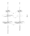
FIGS. 3(a) and 3(b) show conceptually graphs of a waveform detected by the photoacoustic wave measurement device 1 (seeFIG. 2 ) in the comparative example (seeFIG. 3(a) ), as well as a waveform detected by the photoacoustic wave measurement device 1 (seeFIG. 1 ) in the embodiment of the present invention (seeFIG. 3(b) ). - The comparative example (see
FIG. 3(a) ) and the embodiment of the present invention (seeFIG. 3(b) ) do not differ so much in near-end reflection noise A generated directly after the pulsed light P starts to be output from the pulsed-light output end 20a. - In contrast, noise C generated between the near-end reflection noise A and a target signal B to be measured is large in the comparative example (see
FIG. 3(a) ), but small in the embodiment of the present invention (seeFIG. 3(b) ). This is the effect obtained by inserting theoptical fiber 20 into the spacer 18 (particularly, by causing the optical fiber to penetrate the spacer). - In the comparative example (see
FIG. 2 ), the pulsed-light output end 20a is located so close to thepiezoelectric element 14 and theelectrode 16 that the photoacoustic wave (noise C) generated in the vicinity of the pulsed-light output end 20a and reaching thepiezoelectric element 14 becomes large. In contrast, in the embodiment of the present invention (seeFIG. 1 ), the pulsed-light output end 20a is located so far from thepiezoelectric element 14 and theelectrode 16 that the photoacoustic wave (noise C) generated in the vicinity of the pulsed-light output end 20a and reaching thepiezoelectric element 14 becomes small. - In the photoacoustic
wave measurement device 1 of the embodiment of the present invention, theoptical fiber 20 is inserted into (particularly, penetrates) thespacer 18, which can reduce noise included in the photoacoustic signal obtained by the photoacousticwave measurement device 1. - Although the
spacer 18 is a separate member from thearrangement member 34 as mentioned above, thespacer 18 and thearrangement member 34 may be integrally formed together.
Claims (4)
- A photoacoustic wave measurement device, comprising:a light outputting portion that outputs light therefrom;an arrangement member that is disposed between a light output end of the light outputting portion and a measurement object, and which is adapted to allow the light to pass therethrough;a photoacoustic wave detector that receives a photoacoustic wave generated by the light from the measurement object and converts the photoacoustic wave into an electric signal; anda photoacoustic wave transmission member that is disposed between the arrangement member and the photoacoustic wave detector, and which is adapted to allow the photoacoustic wave to pass therethrough, whereinthe photoacoustic wave detector is farther from the measurement object than the light output end, anda part of the light outputting portion is disposed within the photoacoustic wave transmission member.
- The photoacoustic wave measurement device according to claim 1, wherein
the light outputting portion penetrates the photoacoustic wave transmission member. - The photoacoustic wave measurement device according to claim 1 or 2, wherein
the light outputting portion is an optical fiber. - The photoacoustic wave measurement device according to claim 1 or 2, wherein
the photoacoustic wave detector is a piezoelectric element.
Applications Claiming Priority (2)
| Application Number | Priority Date | Filing Date | Title |
|---|---|---|---|
| JP2012181435 | 2012-08-20 | ||
| PCT/JP2013/070263 WO2014030491A1 (en) | 2012-08-20 | 2013-07-19 | Photoacoustic wave meter |
Publications (2)
| Publication Number | Publication Date |
|---|---|
| EP2887059A1 true EP2887059A1 (en) | 2015-06-24 |
| EP2887059A4 EP2887059A4 (en) | 2016-01-20 |
Family
ID=50149802
Family Applications (1)
| Application Number | Title | Priority Date | Filing Date |
|---|---|---|---|
| EP13830910.9A Withdrawn EP2887059A4 (en) | 2012-08-20 | 2013-07-19 | Photoacoustic wave meter |
Country Status (5)
| Country | Link |
|---|---|
| US (1) | US9410842B2 (en) |
| EP (1) | EP2887059A4 (en) |
| JP (1) | JP6059232B2 (en) |
| CN (1) | CN104272101B (en) |
| WO (1) | WO2014030491A1 (en) |
Families Citing this family (3)
| Publication number | Priority date | Publication date | Assignee | Title |
|---|---|---|---|---|
| JP6161941B2 (en) * | 2013-04-15 | 2017-07-12 | 株式会社アドバンテスト | Photoacoustic wave measuring instrument, photoacoustic wave measuring apparatus, method, program, and recording medium |
| US12553864B2 (en) * | 2022-12-21 | 2026-02-17 | Qualcomm Incorporated | Photoacoustic devices and systems including one or more light guide components |
| US12449405B2 (en) * | 2023-05-18 | 2025-10-21 | Qualcomm Incorporated | Photoacoustic device including a light guide system configured to transmit light through an electromagnetic interference (EMI)-reducing layer |
Family Cites Families (30)
| Publication number | Priority date | Publication date | Assignee | Title |
|---|---|---|---|---|
| US4543486A (en) * | 1983-05-20 | 1985-09-24 | The United States Of America As Represented By The Secretary Of The Army | Method and apparatus for using a photoacoustic effect for controlling various processes utilizing laser and ion beams, and the like |
| US5125749A (en) | 1990-09-24 | 1992-06-30 | The Dow Chemical Company | Probe for photoacoustic analysis |
| GB9312327D0 (en) * | 1993-06-15 | 1993-07-28 | British Tech Group | Laser ultrasound probe and ablator |
| JPH10197496A (en) | 1996-12-27 | 1998-07-31 | Kao Corp | Photoacoustic spectroscopy measurement method and measurement device |
| US8326388B2 (en) * | 2002-10-31 | 2012-12-04 | Toshiba Medical Systems Corporation | Method and apparatus for non-invasive measurement of living body characteristics by photoacoustics |
| EP1585440A1 (en) | 2003-01-13 | 2005-10-19 | Glucon Inc. | Photoacoustic assay method and apparatus |
| JP2004351023A (en) * | 2003-05-30 | 2004-12-16 | Olympus Corp | Photoacoustic probe |
| US20050070803A1 (en) * | 2003-09-30 | 2005-03-31 | Cullum Brian M. | Multiphoton photoacoustic spectroscopy system and method |
| JP4829934B2 (en) | 2008-07-11 | 2011-12-07 | キヤノン株式会社 | Inspection device |
| JP5460000B2 (en) * | 2008-08-20 | 2014-04-02 | キヤノン株式会社 | Imaging apparatus and imaging method |
| WO2010024290A1 (en) * | 2008-08-27 | 2010-03-04 | キヤノン株式会社 | Device for processing photo acoustic information relating to living body and method for processing photo acoustic information relating to living body |
| JP4900979B2 (en) * | 2008-08-27 | 2012-03-21 | キヤノン株式会社 | Photoacoustic apparatus and probe for receiving photoacoustic waves |
| JP2010125260A (en) * | 2008-12-01 | 2010-06-10 | Canon Inc | Biological testing apparatus |
| JP5692986B2 (en) * | 2008-12-25 | 2015-04-01 | キヤノン株式会社 | Subject information acquisition device |
| US9351705B2 (en) * | 2009-01-09 | 2016-05-31 | Washington University | Miniaturized photoacoustic imaging apparatus including a rotatable reflector |
| JP5489624B2 (en) * | 2009-10-01 | 2014-05-14 | キヤノン株式会社 | measuring device |
| JP5683213B2 (en) * | 2009-11-17 | 2015-03-11 | キヤノン株式会社 | Image forming apparatus and image forming method |
| JP5538855B2 (en) * | 2009-12-11 | 2014-07-02 | キヤノン株式会社 | Photoacoustic apparatus and method for controlling the apparatus |
| US8879352B2 (en) * | 2010-01-25 | 2014-11-04 | The Arizona Board Of Regents On Behalf Of The University Of Arizona | Ultrasonic/photoacoustic imaging devices and methods |
| JP5623121B2 (en) | 2010-04-27 | 2014-11-12 | キヤノン株式会社 | Subject information acquisition device |
| JP5693043B2 (en) * | 2010-04-28 | 2015-04-01 | キヤノン株式会社 | Subject information acquisition apparatus and subject information acquisition method |
| JP5761935B2 (en) * | 2010-07-22 | 2015-08-12 | キヤノン株式会社 | Subject information acquisition apparatus, subject information acquisition method, and subject information acquisition program |
| JP5627328B2 (en) * | 2010-07-28 | 2014-11-19 | キヤノン株式会社 | Photoacoustic diagnostic equipment |
| JP5574927B2 (en) * | 2010-11-19 | 2014-08-20 | キヤノン株式会社 | measuring device |
| JP5296121B2 (en) * | 2011-02-28 | 2013-09-25 | 株式会社東芝 | Biological information measuring device |
| JP5850633B2 (en) * | 2011-04-12 | 2016-02-03 | キヤノン株式会社 | Subject information acquisition device |
| JP5832182B2 (en) * | 2011-07-19 | 2015-12-16 | キヤノン株式会社 | Acoustic signal receiving apparatus and imaging apparatus |
| JP6139234B2 (en) | 2013-04-15 | 2017-05-31 | 株式会社アドバンテスト | Photoacoustic wave measuring instrument |
| JP6161941B2 (en) | 2013-04-15 | 2017-07-12 | 株式会社アドバンテスト | Photoacoustic wave measuring instrument, photoacoustic wave measuring apparatus, method, program, and recording medium |
| JP6029521B2 (en) | 2013-04-15 | 2016-11-24 | 株式会社アドバンテスト | Photoacoustic wave measuring apparatus, method, program, and recording medium |
-
2013
- 2013-07-19 CN CN201380024121.3A patent/CN104272101B/en active Active
- 2013-07-19 EP EP13830910.9A patent/EP2887059A4/en not_active Withdrawn
- 2013-07-19 US US14/397,939 patent/US9410842B2/en active Active
- 2013-07-19 JP JP2014531557A patent/JP6059232B2/en active Active
- 2013-07-19 WO PCT/JP2013/070263 patent/WO2014030491A1/en not_active Ceased
Also Published As
| Publication number | Publication date |
|---|---|
| US20150122036A1 (en) | 2015-05-07 |
| EP2887059A4 (en) | 2016-01-20 |
| WO2014030491A1 (en) | 2014-02-27 |
| US9410842B2 (en) | 2016-08-09 |
| CN104272101B (en) | 2017-02-08 |
| JPWO2014030491A1 (en) | 2016-07-28 |
| JP6059232B2 (en) | 2017-01-11 |
| CN104272101A (en) | 2015-01-07 |
Similar Documents
| Publication | Publication Date | Title |
|---|---|---|
| EP2704622B1 (en) | Light irradiating apparatus, control method therefor, and object information acquiring apparatus | |
| CN1153547C (en) | Devices for taking in-ear measurements | |
| JP5565463B2 (en) | Pulse wave sensor device | |
| CN101917899A (en) | Optical sensor for determining analyte concentration | |
| US9453761B2 (en) | Photoacoustic wave measurement device | |
| US9410842B2 (en) | Photoacoustic wave measurement device | |
| JP6161941B2 (en) | Photoacoustic wave measuring instrument, photoacoustic wave measuring apparatus, method, program, and recording medium | |
| CN110087544A (en) | Biological substance measuring device and biological substance measuring method | |
| JP5809749B2 (en) | Photoacoustic wave measuring apparatus, method, program, and recording medium | |
| JP2015192742A (en) | Pulse wave detector | |
| EP3243443A1 (en) | Probe for photoacoustic measurement, probe unit comprising same, and photoacoustic measuring device | |
| US20190130553A1 (en) | Information processing apparatus and information processing method | |
| US10551355B2 (en) | Probe and subject information obtaining apparatus using the same | |
| JP6085030B2 (en) | Information detector, information measuring instrument, and information detecting method | |
| US12408840B2 (en) | Component concentration measuring device | |
| JP7134657B2 (en) | Photoacoustic measuring device | |
| US20210015444A1 (en) | Biological sound measuring device, biological sound measurement support method, and biological sound measurement support program | |
| US9532743B2 (en) | Apparatus for detecting tissue hardness of living body | |
| RU68881U1 (en) | STETHOSCOPE | |
| CN109419494A (en) | Vltrasonic device |
Legal Events
| Date | Code | Title | Description |
|---|---|---|---|
| PUAI | Public reference made under article 153(3) epc to a published international application that has entered the european phase |
Free format text: ORIGINAL CODE: 0009012 |
|
| 17P | Request for examination filed |
Effective date: 20141028 |
|
| AK | Designated contracting states |
Kind code of ref document: A1 Designated state(s): AL AT BE BG CH CY CZ DE DK EE ES FI FR GB GR HR HU IE IS IT LI LT LU LV MC MK MT NL NO PL PT RO RS SE SI SK SM TR |
|
| AX | Request for extension of the european patent |
Extension state: BA ME |
|
| DAX | Request for extension of the european patent (deleted) | ||
| RA4 | Supplementary search report drawn up and despatched (corrected) |
Effective date: 20151223 |
|
| RIC1 | Information provided on ipc code assigned before grant |
Ipc: G01N 21/17 20060101ALI20151217BHEP Ipc: A61B 5/00 20060101ALI20151217BHEP Ipc: G01N 29/00 20060101AFI20151217BHEP |
|
| 17Q | First examination report despatched |
Effective date: 20181123 |
|
| RAP1 | Party data changed (applicant data changed or rights of an application transferred) |
Owner name: ADVANTEST CORPORATION |
|
| STAA | Information on the status of an ep patent application or granted ep patent |
Free format text: STATUS: THE APPLICATION HAS BEEN WITHDRAWN |
|
| 18W | Application withdrawn |
Effective date: 20191009 |