EP2887043A1 - Assessing integrity of bonded joints - Google Patents
Assessing integrity of bonded joints Download PDFInfo
- Publication number
- EP2887043A1 EP2887043A1 EP13275326.0A EP13275326A EP2887043A1 EP 2887043 A1 EP2887043 A1 EP 2887043A1 EP 13275326 A EP13275326 A EP 13275326A EP 2887043 A1 EP2887043 A1 EP 2887043A1
- Authority
- EP
- European Patent Office
- Prior art keywords
- optical fibre
- passage
- joint
- component
- assembly according
- Prior art date
- Legal status (The legal status is an assumption and is not a legal conclusion. Google has not performed a legal analysis and makes no representation as to the accuracy of the status listed.)
- Ceased
Links
- 239000013307 optical fiber Substances 0.000 claims abstract description 54
- 238000000034 method Methods 0.000 claims abstract description 10
- 239000000853 adhesive Substances 0.000 claims description 11
- 230000001070 adhesive effect Effects 0.000 claims description 11
- 239000002131 composite material Substances 0.000 claims description 8
- 239000002390 adhesive tape Substances 0.000 claims description 5
- 230000003287 optical effect Effects 0.000 claims description 4
- 239000000835 fiber Substances 0.000 description 25
- 229920006332 epoxy adhesive Polymers 0.000 description 3
- 238000005452 bending Methods 0.000 description 2
- 239000003822 epoxy resin Substances 0.000 description 2
- 229920000647 polyepoxide Polymers 0.000 description 2
- 229920003319 Araldite® Polymers 0.000 description 1
- OKTJSMMVPCPJKN-UHFFFAOYSA-N Carbon Chemical compound [C] OKTJSMMVPCPJKN-UHFFFAOYSA-N 0.000 description 1
- 230000002411 adverse Effects 0.000 description 1
- 239000004411 aluminium Substances 0.000 description 1
- 229910052782 aluminium Inorganic materials 0.000 description 1
- XAGFODPZIPBFFR-UHFFFAOYSA-N aluminium Chemical compound [Al] XAGFODPZIPBFFR-UHFFFAOYSA-N 0.000 description 1
- 230000000712 assembly Effects 0.000 description 1
- 238000000429 assembly Methods 0.000 description 1
- 229910052799 carbon Inorganic materials 0.000 description 1
- 230000001010 compromised effect Effects 0.000 description 1
- 238000001514 detection method Methods 0.000 description 1
- 238000010586 diagram Methods 0.000 description 1
- 238000005553 drilling Methods 0.000 description 1
- 238000007689 inspection Methods 0.000 description 1
- 230000007774 longterm Effects 0.000 description 1
- 229910052751 metal Inorganic materials 0.000 description 1
- 239000002184 metal Substances 0.000 description 1
- 239000004810 polytetrafluoroethylene Substances 0.000 description 1
- 229920001343 polytetrafluoroethylene Polymers 0.000 description 1
- 239000011208 reinforced composite material Substances 0.000 description 1
- 230000007704 transition Effects 0.000 description 1
Images


Classifications
-
- B—PERFORMING OPERATIONS; TRANSPORTING
- B29—WORKING OF PLASTICS; WORKING OF SUBSTANCES IN A PLASTIC STATE IN GENERAL
- B29C—SHAPING OR JOINING OF PLASTICS; SHAPING OF MATERIAL IN A PLASTIC STATE, NOT OTHERWISE PROVIDED FOR; AFTER-TREATMENT OF THE SHAPED PRODUCTS, e.g. REPAIRING
- B29C66/00—General aspects of processes or apparatus for joining preformed parts
- B29C66/01—General aspects dealing with the joint area or with the area to be joined
- B29C66/05—Particular design of joint configurations
- B29C66/10—Particular design of joint configurations particular design of the joint cross-sections
- B29C66/11—Joint cross-sections comprising a single joint-segment, i.e. one of the parts to be joined comprising a single joint-segment in the joint cross-section
- B29C66/112—Single lapped joints
- B29C66/1122—Single lap to lap joints, i.e. overlap joints
-
- G—PHYSICS
- G01—MEASURING; TESTING
- G01M—TESTING STATIC OR DYNAMIC BALANCE OF MACHINES OR STRUCTURES; TESTING OF STRUCTURES OR APPARATUS, NOT OTHERWISE PROVIDED FOR
- G01M11/00—Testing of optical apparatus; Testing structures by optical methods not otherwise provided for
- G01M11/08—Testing mechanical properties
- G01M11/083—Testing mechanical properties by using an optical fiber in contact with the device under test [DUT]
- G01M11/086—Details about the embedment of the optical fiber within the DUT
-
- G—PHYSICS
- G01—MEASURING; TESTING
- G01M—TESTING STATIC OR DYNAMIC BALANCE OF MACHINES OR STRUCTURES; TESTING OF STRUCTURES OR APPARATUS, NOT OTHERWISE PROVIDED FOR
- G01M5/00—Investigating the elasticity of structures, e.g. deflection of bridges or air-craft wings
- G01M5/0041—Investigating the elasticity of structures, e.g. deflection of bridges or air-craft wings by determining deflection or stress
-
- G—PHYSICS
- G01—MEASURING; TESTING
- G01M—TESTING STATIC OR DYNAMIC BALANCE OF MACHINES OR STRUCTURES; TESTING OF STRUCTURES OR APPARATUS, NOT OTHERWISE PROVIDED FOR
- G01M5/00—Investigating the elasticity of structures, e.g. deflection of bridges or air-craft wings
- G01M5/0091—Investigating the elasticity of structures, e.g. deflection of bridges or air-craft wings by using electromagnetic excitation or detection
-
- B—PERFORMING OPERATIONS; TRANSPORTING
- B29—WORKING OF PLASTICS; WORKING OF SUBSTANCES IN A PLASTIC STATE IN GENERAL
- B29C—SHAPING OR JOINING OF PLASTICS; SHAPING OF MATERIAL IN A PLASTIC STATE, NOT OTHERWISE PROVIDED FOR; AFTER-TREATMENT OF THE SHAPED PRODUCTS, e.g. REPAIRING
- B29C65/00—Joining or sealing of preformed parts, e.g. welding of plastics materials; Apparatus therefor
- B29C65/48—Joining or sealing of preformed parts, e.g. welding of plastics materials; Apparatus therefor using adhesives, i.e. using supplementary joining material; solvent bonding
-
- B—PERFORMING OPERATIONS; TRANSPORTING
- B29—WORKING OF PLASTICS; WORKING OF SUBSTANCES IN A PLASTIC STATE IN GENERAL
- B29C—SHAPING OR JOINING OF PLASTICS; SHAPING OF MATERIAL IN A PLASTIC STATE, NOT OTHERWISE PROVIDED FOR; AFTER-TREATMENT OF THE SHAPED PRODUCTS, e.g. REPAIRING
- B29C65/00—Joining or sealing of preformed parts, e.g. welding of plastics materials; Apparatus therefor
- B29C65/48—Joining or sealing of preformed parts, e.g. welding of plastics materials; Apparatus therefor using adhesives, i.e. using supplementary joining material; solvent bonding
- B29C65/4805—Joining or sealing of preformed parts, e.g. welding of plastics materials; Apparatus therefor using adhesives, i.e. using supplementary joining material; solvent bonding characterised by the type of adhesives
- B29C65/483—Reactive adhesives, e.g. chemically curing adhesives
- B29C65/4835—Heat curing adhesives
-
- B—PERFORMING OPERATIONS; TRANSPORTING
- B29—WORKING OF PLASTICS; WORKING OF SUBSTANCES IN A PLASTIC STATE IN GENERAL
- B29C—SHAPING OR JOINING OF PLASTICS; SHAPING OF MATERIAL IN A PLASTIC STATE, NOT OTHERWISE PROVIDED FOR; AFTER-TREATMENT OF THE SHAPED PRODUCTS, e.g. REPAIRING
- B29C65/00—Joining or sealing of preformed parts, e.g. welding of plastics materials; Apparatus therefor
- B29C65/82—Testing the joint
-
- B—PERFORMING OPERATIONS; TRANSPORTING
- B29—WORKING OF PLASTICS; WORKING OF SUBSTANCES IN A PLASTIC STATE IN GENERAL
- B29C—SHAPING OR JOINING OF PLASTICS; SHAPING OF MATERIAL IN A PLASTIC STATE, NOT OTHERWISE PROVIDED FOR; AFTER-TREATMENT OF THE SHAPED PRODUCTS, e.g. REPAIRING
- B29C66/00—General aspects of processes or apparatus for joining preformed parts
- B29C66/40—General aspects of joining substantially flat articles, e.g. plates, sheets or web-like materials; Making flat seams in tubular or hollow articles; Joining single elements to substantially flat surfaces
- B29C66/41—Joining substantially flat articles ; Making flat seams in tubular or hollow articles
- B29C66/45—Joining of substantially the whole surface of the articles
-
- B—PERFORMING OPERATIONS; TRANSPORTING
- B29—WORKING OF PLASTICS; WORKING OF SUBSTANCES IN A PLASTIC STATE IN GENERAL
- B29C—SHAPING OR JOINING OF PLASTICS; SHAPING OF MATERIAL IN A PLASTIC STATE, NOT OTHERWISE PROVIDED FOR; AFTER-TREATMENT OF THE SHAPED PRODUCTS, e.g. REPAIRING
- B29C66/00—General aspects of processes or apparatus for joining preformed parts
- B29C66/50—General aspects of joining tubular articles; General aspects of joining long products, i.e. bars or profiled elements; General aspects of joining single elements to tubular articles, hollow articles or bars; General aspects of joining several hollow-preforms to form hollow or tubular articles
-
- B—PERFORMING OPERATIONS; TRANSPORTING
- B29—WORKING OF PLASTICS; WORKING OF SUBSTANCES IN A PLASTIC STATE IN GENERAL
- B29C—SHAPING OR JOINING OF PLASTICS; SHAPING OF MATERIAL IN A PLASTIC STATE, NOT OTHERWISE PROVIDED FOR; AFTER-TREATMENT OF THE SHAPED PRODUCTS, e.g. REPAIRING
- B29C66/00—General aspects of processes or apparatus for joining preformed parts
- B29C66/69—General aspects of joining filaments
-
- B—PERFORMING OPERATIONS; TRANSPORTING
- B29—WORKING OF PLASTICS; WORKING OF SUBSTANCES IN A PLASTIC STATE IN GENERAL
- B29C—SHAPING OR JOINING OF PLASTICS; SHAPING OF MATERIAL IN A PLASTIC STATE, NOT OTHERWISE PROVIDED FOR; AFTER-TREATMENT OF THE SHAPED PRODUCTS, e.g. REPAIRING
- B29C66/00—General aspects of processes or apparatus for joining preformed parts
- B29C66/70—General aspects of processes or apparatus for joining preformed parts characterised by the composition, physical properties or the structure of the material of the parts to be joined; Joining with non-plastics material
- B29C66/72—General aspects of processes or apparatus for joining preformed parts characterised by the composition, physical properties or the structure of the material of the parts to be joined; Joining with non-plastics material characterised by the structure of the material of the parts to be joined
- B29C66/721—Fibre-reinforced materials
-
- B—PERFORMING OPERATIONS; TRANSPORTING
- B29—WORKING OF PLASTICS; WORKING OF SUBSTANCES IN A PLASTIC STATE IN GENERAL
- B29L—INDEXING SCHEME ASSOCIATED WITH SUBCLASS B29C, RELATING TO PARTICULAR ARTICLES
- B29L2011/00—Optical elements, e.g. lenses, prisms
- B29L2011/0075—Light guides, optical cables
-
- B—PERFORMING OPERATIONS; TRANSPORTING
- B29—WORKING OF PLASTICS; WORKING OF SUBSTANCES IN A PLASTIC STATE IN GENERAL
- B29L—INDEXING SCHEME ASSOCIATED WITH SUBCLASS B29C, RELATING TO PARTICULAR ARTICLES
- B29L2031/00—Other particular articles
- B29L2031/08—Blades for rotors, stators, fans, turbines or the like, e.g. screw propellers
- B29L2031/082—Blades, e.g. for helicopters
- B29L2031/085—Wind turbine blades
-
- B—PERFORMING OPERATIONS; TRANSPORTING
- B29—WORKING OF PLASTICS; WORKING OF SUBSTANCES IN A PLASTIC STATE IN GENERAL
- B29L—INDEXING SCHEME ASSOCIATED WITH SUBCLASS B29C, RELATING TO PARTICULAR ARTICLES
- B29L2031/00—Other particular articles
- B29L2031/30—Vehicles, e.g. ships or aircraft, or body parts thereof
- B29L2031/3076—Aircrafts
- B29L2031/3082—Fuselages
-
- B—PERFORMING OPERATIONS; TRANSPORTING
- B29—WORKING OF PLASTICS; WORKING OF SUBSTANCES IN A PLASTIC STATE IN GENERAL
- B29L—INDEXING SCHEME ASSOCIATED WITH SUBCLASS B29C, RELATING TO PARTICULAR ARTICLES
- B29L2031/00—Other particular articles
- B29L2031/30—Vehicles, e.g. ships or aircraft, or body parts thereof
- B29L2031/3076—Aircrafts
- B29L2031/3085—Wings
-
- B—PERFORMING OPERATIONS; TRANSPORTING
- B64—AIRCRAFT; AVIATION; COSMONAUTICS
- B64D—EQUIPMENT FOR FITTING IN OR TO AIRCRAFT; FLIGHT SUITS; PARACHUTES; ARRANGEMENT OR MOUNTING OF POWER PLANTS OR PROPULSION TRANSMISSIONS IN AIRCRAFT
- B64D45/00—Aircraft indicators or protectors not otherwise provided for
- B64D2045/0085—Devices for aircraft health monitoring, e.g. monitoring flutter or vibration
-
- F—MECHANICAL ENGINEERING; LIGHTING; HEATING; WEAPONS; BLASTING
- F03—MACHINES OR ENGINES FOR LIQUIDS; WIND, SPRING, OR WEIGHT MOTORS; PRODUCING MECHANICAL POWER OR A REACTIVE PROPULSIVE THRUST, NOT OTHERWISE PROVIDED FOR
- F03D—WIND MOTORS
- F03D17/00—Monitoring or testing of wind motors, e.g. diagnostics
-
- Y—GENERAL TAGGING OF NEW TECHNOLOGICAL DEVELOPMENTS; GENERAL TAGGING OF CROSS-SECTIONAL TECHNOLOGIES SPANNING OVER SEVERAL SECTIONS OF THE IPC; TECHNICAL SUBJECTS COVERED BY FORMER USPC CROSS-REFERENCE ART COLLECTIONS [XRACs] AND DIGESTS
- Y02—TECHNOLOGIES OR APPLICATIONS FOR MITIGATION OR ADAPTATION AGAINST CLIMATE CHANGE
- Y02P—CLIMATE CHANGE MITIGATION TECHNOLOGIES IN THE PRODUCTION OR PROCESSING OF GOODS
- Y02P70/00—Climate change mitigation technologies in the production process for final industrial or consumer products
- Y02P70/50—Manufacturing or production processes characterised by the final manufactured product
Definitions
- This invention relates to assessment of the integrity of bonded joints in components and in particular to assessment of the bond integrity of fibre reinforced composite structures.
- the integrity of high strength bonded structures is often critical, for example in aircraft, and any failure of such a structure, like a carbon fibre wing, for example, could be critical to the safety of the aircraft.
- the problem of assessing bond integrity may be equally important for structures which are not necessarily safety critical but which are either extremely expensive, such as large wind turbines, or which are expected to perform for long periods reliably and which may be difficult to access, such as building structures.
- Such bonded structures may be of fibre-reinforced composite material or may be metallic structures, such as bonded aluminium vehicle bodies.
- Bonded structures likely to cause particular difficulty with both inspection and access, for optical fibre damage detection are airframe structures, in particular wings and fuselages, where a clean aerodynamic surface is required on one side of the structure and where they may be no accessible edge to the structure from which to access the ends of optical fibres embedded in the structure.
- an assembly having a bonded joint monitored for bond integrity, the assembly comprising first and second components each defining a bonding surface thereon, the joint being formed between the bonding surfaces, the first component defining a passage therethrough from the bonding surface to an exterior of the component, the joint including an optical fibre extending along the joint between the bonding surfaces, through the passage and emerging from the passage to the exterior of the component.
- the passage may be directed and dimensioned whereby to allow the optical fibre to pass therethrough while defining a bend radius which allows light to pass along the optical fibre.
- the passage may be angled with respect to the joint.
- the assembly preferably includes a support for the emerging optical fibre and the support may include an end connector for the optical fibre attached to the support.
- the support may further include a casing for the emerging optical fibre such as a flexible hollow tube.
- the casing may penetrate the passage, whereby to give support to the optical fibre from within the first component.
- the optical fibre is likely to be vulnerable to damage, as it changes direction when turning through the passage from the joint.
- the optical fibre may therefore be potted within the passage, for example in an epoxy resin, to give the fibre further support in this vulnerable length of fibre.
- the optical fibre may have light input at one end thereof and a light sensing arrangement at or near the other end thereof.
- the optical fibre may form a loop within the joint.
- a number of optical fibres may pass through a single passage rather than a number of passages.
- the assembly of the invention may be of particular benefit in high strength fibre-reinforced composite structures where the integrity of bonds between composite components or parts of a composite structure is critical.
- Such structures are building or vehicle structures, in particular aircraft components such as aerofoils, fuselages and components thereof.
- at least one of the first and second components may comprise a fibre-reinforced composite structure and may comprise an aircraft structural airframe component.
- a method of constructing an assembly having a bonded joint monitored for bond integrity comprising first and second components each defining a bonding surface thereon, the joint being formed between the bonding surfaces, the first component defining a passage therethrough from the bonding surface to an exterior of the component, the joint including an optical fibre extending along the joint between the bonding surfaces, through the passage and emerging from the passage to the exterior of the component, the method including the steps of passing the optical fibre through the passage and adhering the optical fibre to the bonding surface of the first component, bringing the two bonding surfaces together and forming the bond.
- the step of adhering the optical fibre to the bonding surface of the first component may comprise applying adhesive to adhere the optical fibre to the bonding surface at selected locations on the bonding surface and securing the optical fibre in position while the adhesive sets.
- the step of securing the optical fibre in position may comprise applying adhesive tape to the bonding surface of the first component whereby to secure the optical fibre in position while the adhesive sets.
- the adhesive tape may be applied to the bonding surface of the first component over the adhesive.
- adhesive tape may be applied to the bonding surface over an entrance to the passage.
- an assembly according to the invention comprises first and second fibre-reinforced composite components 1, 2 each having a bonding surface 3, 4 facing the other.
- a bonded joint 5, is formed between the bonding surfaces 3, 4. Bonding together the bonding surfaces of the first and second components 1, 2 is a layer 6 of epoxy resin adhesive.
- a metal bracket 8 Attached to an exterior surface 7 of the first component 1 is a metal bracket 8.
- the bracket 8 supports a pair of a fibre end connectors 9, 10 (only one of which appears in Figure 1 ) each of which is connected to an end of an optical fibre 11.
- the optical fibre 11 extends in a loop 12 (see also Figures 3 and 4 ) within the joint 5 and has radiused terminal portions 13, 14 extending from the joint 5 to the end connectors 9, 10.
- Each radiused terminal portion 13, 14 passes through a circular drilled passage 15.
- the passage 15 has a component portion 16, drilled through the first component 1, and a bracket portion 17 drilled through the bracket 8. Both portions 16 and 17 are drilled at an angle of 45 deg. to the bonding surface 3. It will be observed that the passage is of considerably larger diameter than the optical fibre 11, thereby allowing the fibre to curve within the passage. It would clearly be possible to form the passage 15 with curvature to match the diameter and intended curvature of the optical fibre 11. This could be achieved by laser drilling, for example, or an alternative forming process. However, for simplicity and to save cost, it is simpler simply to drill conventionally a hole for the passage which is of larger diameter.
- the point of entry 24 of the optical fibre 11 into the joint 5 is vulnerable, owing to the transition from it being relatively straight within the joint 5 to the much tighter curvature of the terminal portions 13, 14. Great care when feeding the fibre 11 through the passage 15 is therefore required.
- the terminal portions 13, 14 emerging from the passage 15 are also vulnerable and some form of protection is likely to be required.
- the long term functionality of optical fibre can be compromised if subjected to excessively tight bends. Thus, a suitable bend radius must be calculated.
- a 4.5 mm passage 15 is drilled in the first component 1 at approximately 45° and burrs are removed from the edges of the passage.
- a length of single mode fibre 11 is then fed through the passage and held in place using adhesive tape 18.
- the tape 18 is to ensure that the fibre 11 emerges from the passage at a shallow angle which will minimise local stresses on the fibre and reduce the risk of it breaking.
- Short lengths 19, 20 of PTFE tubing are then fitted over the fibre 11 on the other side of the first component 1 with their ends being placed into the passage 15. This tubing should not enter the joint 5.
- the passage 15 is then filled with epoxy adhesive 21, fixing the fibre 11 and the sleeves 19, 20 in place.
- the adhesive 21 has cured, the tape 18 is removed (it should be peeled away in the direction the fibre 11 emerges from the passage 15). This ensures that the fibre is not subjected to sharp bending at the point that it emerges from the substructure hole.
- Araldite 2014 adhesive was chosen to encapsulate the fibre because of its low shrinkage.
- the fibre 11 is then tacked to the bonding surface 3 of the first component 1. There are two reasons to tack the fibre; firstly, for protection and, secondly, to accurately position the fibre. Figure 4 shows how this would work.
- the fibre 11 is laid out and held into place using short lengths of tape 22.
- small quantities of epoxy adhesive 23 are applied to several points on the fibre 11 to tack it to the surface 1.
- the two components 1, 2 are bonded together using epoxy adhesive 6.
- weights or vacuum can be applied to compress the joint.
- the point at which the fibre 11 enters the joint 5 can be subject to tight bending and lateral forces during the bonding process.
- the integrity of the optical fibre 11 can be determined using a continuity test. Light is passed down the fibre 11 from a cable 24 attached to one 9 of the end connectors and, if light appears at the end connector 10 at the other end of the fibre 11, as shown in figure 5 , the integrity of the joint 5 and of the optical fibre 11 is confirmed. The excess loss associated with incorporating the fibre into the bond line is likely to be of the order of 1.5 dB for the fibre loop.
- Optical fibre cannot be subjected to sharp bends for two reasons. Firstly, in time, the optical fibre is likely to break at a sharp bend and, secondly, a sharp bend will cause a significant optical loss. Thus, for best operation of optical fibre, it is best to limit the sharpness of bends. This section quantifies how the features of the passage 15 determine the bend radius of the optical fibre 11.
Landscapes
- Physics & Mathematics (AREA)
- Engineering & Computer Science (AREA)
- General Physics & Mathematics (AREA)
- Aviation & Aerospace Engineering (AREA)
- Mechanical Engineering (AREA)
- Electromagnetism (AREA)
- Chemical & Material Sciences (AREA)
- Analytical Chemistry (AREA)
- Lining Or Joining Of Plastics Or The Like (AREA)
Abstract
There is provided apparatus and a method for assessing the integrity of a bonded joint in an assembly. The assembly has a bonded joint (5) monitored for bond integrity and comprises first (1) and second (2) components each defining a bonding surface (3, 4); the joint (5) is formed between the bonding surfaces (3, 4) and the first component (1) defines a passage (15) therethrough from the bonding surface to an exterior of the component. The joint (5) includes an optical fibre (11) extending along the joint (5) between the bonding surfaces (3, 4), through the passage (15) and emerging from the passage (15) to the exterior of the component. The method of constructing the assembly includes the steps of passing the optical fibre (11) through the passage (15) and adhering the optical fibre to the bonding surface (1) of the first component (1), thus bringing the two bonding surfaces (3, 4) together and forming the bond (5).
Description
- This invention relates to assessment of the integrity of bonded joints in components and in particular to assessment of the bond integrity of fibre reinforced composite structures.
- The integrity of high strength bonded structures is often critical, for example in aircraft, and any failure of such a structure, like a carbon fibre wing, for example, could be critical to the safety of the aircraft. The problem of assessing bond integrity may be equally important for structures which are not necessarily safety critical but which are either extremely expensive, such as large wind turbines, or which are expected to perform for long periods reliably and which may be difficult to access, such as building structures.
- Such bonded structures may be of fibre-reinforced composite material or may be metallic structures, such as bonded aluminium vehicle bodies.
- It is known to place fibres within fibre-reinforced composite components whose failure, due to impact damage for example, may send an electrical signal to a processor to alert an operator. To date, however, no such solution is known for assessing the integrity of bonds between parts of a structure. It is envisaged that a particular difficulty with such a system would be getting damage information from the bond as the bond is, by definition, located between parts of a unified structure. In addition, any edges of such a bonded joint will often be inaccessible owing to the way in which the component is structured. In assemblies containing bonded joints, those joints may butt up against one another making the edge of the joint inaccessible. Where the bond edge is accessible, an optical fibre cannot emerge through it without protection as it will be liable to break. Protection schemes, such as tubing, are likely to adversely affect the strength of the bond, making such an approach inappropriate.
- Bonded structures likely to cause particular difficulty with both inspection and access, for optical fibre damage detection, are airframe structures, in particular wings and fuselages, where a clean aerodynamic surface is required on one side of the structure and where they may be no accessible edge to the structure from which to access the ends of optical fibres embedded in the structure.
- According to a first aspect of the present invention there is provided an assembly having a bonded joint monitored for bond integrity, the assembly comprising first and second components each defining a bonding surface thereon, the joint being formed between the bonding surfaces, the first component defining a passage therethrough from the bonding surface to an exterior of the component, the joint including an optical fibre extending along the joint between the bonding surfaces, through the passage and emerging from the passage to the exterior of the component.
- The passage may be directed and dimensioned whereby to allow the optical fibre to pass therethrough while defining a bend radius which allows light to pass along the optical fibre. To this end, the passage may be angled with respect to the joint.
- The assembly preferably includes a support for the emerging optical fibre and the support may include an end connector for the optical fibre attached to the support.
- The support may further include a casing for the emerging optical fibre such as a flexible hollow tube.
- The casing may penetrate the passage, whereby to give support to the optical fibre from within the first component.
- The optical fibre is likely to be vulnerable to damage, as it changes direction when turning through the passage from the joint. The optical fibre may therefore be potted within the passage, for example in an epoxy resin, to give the fibre further support in this vulnerable length of fibre.
- The optical fibre may have light input at one end thereof and a light sensing arrangement at or near the other end thereof. For such an arrangement, the optical fibre may form a loop within the joint.
- For reasons of structural integrity of the assembly, a number of optical fibres may pass through a single passage rather than a number of passages.
- The assembly of the invention may be of particular benefit in high strength fibre-reinforced composite structures where the integrity of bonds between composite components or parts of a composite structure is critical. Examples of such structures are building or vehicle structures, in particular aircraft components such as aerofoils, fuselages and components thereof. Thus, at least one of the first and second components may comprise a fibre-reinforced composite structure and may comprise an aircraft structural airframe component.
- According to a second aspect of the present invention there is provided a method of constructing an assembly having a bonded joint monitored for bond integrity, the assembly comprising first and second components each defining a bonding surface thereon, the joint being formed between the bonding surfaces, the first component defining a passage therethrough from the bonding surface to an exterior of the component, the joint including an optical fibre extending along the joint between the bonding surfaces, through the passage and emerging from the passage to the exterior of the component, the method including the steps of passing the optical fibre through the passage and adhering the optical fibre to the bonding surface of the first component, bringing the two bonding surfaces together and forming the bond.
- The step of adhering the optical fibre to the bonding surface of the first component may comprise applying adhesive to adhere the optical fibre to the bonding surface at selected locations on the bonding surface and securing the optical fibre in position while the adhesive sets.
- The step of securing the optical fibre in position may comprise applying adhesive tape to the bonding surface of the first component whereby to secure the optical fibre in position while the adhesive sets. The adhesive tape may be applied to the bonding surface of the first component over the adhesive.
- In order to protect the vulnerable optical fibre passing through the passage in the first component, while securing the optical fibre in position, adhesive tape may be applied to the bonding surface over an entrance to the passage.
- The invention will now be further described by way of example, with reference to the accompanying drawings in which:-
-
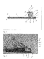
Figure 1 is a schematic vertical section through an assembly according to the invention; -
Figure 2 is a perspective view of the assembly ofFigure 1 having adhesive injected into a passage; -
Figure 3 is a perspective view of part of the assembly ofFigure 2 , inverted; -
Figure 4 is a perspective view of the bonding face of a first component of the assembly ofFigure 2 ; -
Figure 5 is a perspective end view of the assembly ofFigure 2 , connected to a light source, and -
Figure 6 is a diagram of an assembly according to the invention, showing various angles and dimensions. - In
Figure 1 an assembly according to the invention comprises first and second fibre-reinforcedcomposite components 1, 2 each having abonding surface bonding surfaces second components 1, 2 is a layer 6 of epoxy resin adhesive. - Attached to an
exterior surface 7 of the first component 1 is a metal bracket 8. The bracket 8 supports a pair of afibre end connectors 9, 10 (only one of which appears inFigure 1 ) each of which is connected to an end of an optical fibre 11. The optical fibre 11 extends in a loop 12 (see alsoFigures 3 and 4 ) within the joint 5 and has radiusedterminal portions end connectors - Each
radiused terminal portion passage 15. Thepassage 15 has acomponent portion 16, drilled through the first component 1, and abracket portion 17 drilled through the bracket 8. Bothportions bonding surface 3. It will be observed that the passage is of considerably larger diameter than the optical fibre 11, thereby allowing the fibre to curve within the passage. It would clearly be possible to form thepassage 15 with curvature to match the diameter and intended curvature of the optical fibre 11. This could be achieved by laser drilling, for example, or an alternative forming process. However, for simplicity and to save cost, it is simpler simply to drill conventionally a hole for the passage which is of larger diameter. - The point of
entry 24 of the optical fibre 11 into the joint 5 is vulnerable, owing to the transition from it being relatively straight within the joint 5 to the much tighter curvature of theterminal portions passage 15 is therefore required. Theterminal portions passage 15 are also vulnerable and some form of protection is likely to be required. The long term functionality of optical fibre can be compromised if subjected to excessively tight bends. Thus, a suitable bend radius must be calculated. - In this example, a 4.5
mm passage 15 is drilled in the first component 1 at approximately 45° and burrs are removed from the edges of the passage. A length of single mode fibre 11 is then fed through the passage and held in place usingadhesive tape 18. Thetape 18 is to ensure that the fibre 11 emerges from the passage at a shallow angle which will minimise local stresses on the fibre and reduce the risk of it breaking. -
Short lengths 19, 20 of PTFE tubing are then fitted over the fibre 11 on the other side of the first component 1 with their ends being placed into thepassage 15. This tubing should not enter the joint 5. - Referring to
Figure 2 , it can be seen that thepassage 15 is then filled withepoxy adhesive 21, fixing the fibre 11 and thesleeves 19, 20 in place. Once theadhesive 21 has cured, thetape 18 is removed (it should be peeled away in the direction the fibre 11 emerges from the passage 15). This ensures that the fibre is not subjected to sharp bending at the point that it emerges from the substructure hole. Araldite 2014 adhesive was chosen to encapsulate the fibre because of its low shrinkage. - The fibre 11 is then tacked to the
bonding surface 3 of the first component 1. There are two reasons to tack the fibre; firstly, for protection and, secondly, to accurately position the fibre.Figure 4 shows how this would work. The fibre 11 is laid out and held into place using short lengths of tape 22. Then small quantities of epoxy adhesive 23 are applied to several points on the fibre 11 to tack it to the surface 1. - Finally, the two
components 1, 2 are bonded together using epoxy adhesive 6. During the bonding step, weights or vacuum can be applied to compress the joint. - Referring to
Figures 1 and5 , the point at which the fibre 11 enters the joint 5 can be subject to tight bending and lateral forces during the bonding process. The integrity of the optical fibre 11 can be determined using a continuity test. Light is passed down the fibre 11 from acable 24 attached to one 9 of the end connectors and, if light appears at theend connector 10 at the other end of the fibre 11, as shown infigure 5 , the integrity of the joint 5 and of the optical fibre 11 is confirmed. The excess loss associated with incorporating the fibre into the bond line is likely to be of the order of 1.5 dB for the fibre loop. - Optical fibre cannot be subjected to sharp bends for two reasons. Firstly, in time, the optical fibre is likely to break at a sharp bend and, secondly, a sharp bend will cause a significant optical loss. Thus, for best operation of optical fibre, it is best to limit the sharpness of bends. This section quantifies how the features of the
passage 15 determine the bend radius of the optical fibre 11. - Using the equation:

- Where d is the diameter of the passage/hole, θ is the angle of the hole from horizontal
- and l is the longest axis of the hole at its end.

Thus,

Claims (15)
- An assembly having a bonded joint monitored for bond integrity, the assembly comprising first and second components each defining a bonding surface thereon, the joint being formed between the bonding surfaces, the first component defining a passage therethrough from the bonding surface to an exterior of the component, the joint including an optical fibre extending along the joint between the bonding surfaces, through the passage and emerging from the passage to the exterior of the component.
- An assembly according to claim 1, in which the passage is directed and dimensioned whereby to allow the optical fibre to pass therethrough while defining a bend radius which allows light to pass along the optical fibre.
- An assembly according to claim 2, in which the passage is angled with respect to the joint.
- An assembly according to claim 1, 2 or 3, including a support for the emerging optical fibre.
- An assembly according to claim 4, in which the support includes an end connector for the optical fibre attached to the support.
- An assembly according to claim 4 or 5, including a casing for the emerging optical fibre.
- An assembly according to claim 6, in which the casing penetrates the passage.
- An assembly according to any of claims 4 to 7, in which the optical fibre is potted within the passage.
- An assembly according to any preceding claim, in which the optical fibre forms a loop within the joint.
- An assembly according to any preceding claim, including a number of optical fibres passing through a single passage.
- An assembly according to any preceding claim, in which at least one of the first and second components comprises a fibre-reinforced composite structure.
- An assembly according to claim 11, comprising an aircraft structural airframe component.
- A method of constructing an assembly having a bonded joint monitored for bond integrity, the assembly comprising first and second components each defining a bonding surface thereon, the joint being formed between the bonding surfaces, the first component defining a passage therethrough from the bonding surface to an exterior of the component, the joint including an optical fibre extending along the joint between the bonding surfaces, through the passage and emerging from the passage to the exterior of the component, the method including the steps of passing the optical fibre through the passage and adhering the optical fibre to the bonding surface of the first component, bringing the two bonding surfaces together and forming the bond.
- A method according to claim 13, in which the step of adhering the optical fibre to the bonding surface of the first component comprises applying adhesive to adhere the optical fibre to the bonding surface at selected locations on the bonding surface and securing the optical fibre in position while the adhesive sets.
- A method according to claim 14, in which the step of securing the optical fibre in position comprises applying adhesive tape to the bonding surface of the first component whereby to secure the optical fibre in position while the adhesive sets.
Priority Applications (5)
| Application Number | Priority Date | Filing Date | Title |
|---|---|---|---|
| EP13275326.0A EP2887043A1 (en) | 2013-12-19 | 2013-12-19 | Assessing integrity of bonded joints |
| EP14811940.7A EP3084384B1 (en) | 2013-12-19 | 2014-12-15 | Assessing integrity of bonded joints |
| ES14811940T ES2737624T3 (en) | 2013-12-19 | 2014-12-15 | Integrity evaluation of joined couplings |
| US15/105,263 US10359338B2 (en) | 2013-12-19 | 2014-12-15 | Assessing integrity of bonded joints |
| PCT/EP2014/077820 WO2015091390A1 (en) | 2013-12-19 | 2014-12-15 | Assessing integrity of bonded joints |
Applications Claiming Priority (1)
| Application Number | Priority Date | Filing Date | Title |
|---|---|---|---|
| EP13275326.0A EP2887043A1 (en) | 2013-12-19 | 2013-12-19 | Assessing integrity of bonded joints |
Publications (1)
| Publication Number | Publication Date |
|---|---|
| EP2887043A1 true EP2887043A1 (en) | 2015-06-24 |
Family
ID=49920081
Family Applications (1)
| Application Number | Title | Priority Date | Filing Date |
|---|---|---|---|
| EP13275326.0A Ceased EP2887043A1 (en) | 2013-12-19 | 2013-12-19 | Assessing integrity of bonded joints |
Country Status (1)
| Country | Link |
|---|---|
| EP (1) | EP2887043A1 (en) |
Citations (2)
| Publication number | Priority date | Publication date | Assignee | Title |
|---|---|---|---|---|
| US5604836A (en) * | 1995-12-11 | 1997-02-18 | United Technologies Corporation | Optical fiber entry strain relief interface for compression-molded structures |
| WO2000026710A1 (en) * | 1998-10-29 | 2000-05-11 | The Government Of The United States Of America As Represented By The Secretary Of The Navy | Apparatus for ingress and egress of fiber optic sensor leads from the surface of composite parts and a method for the manufacture thereof |
-
2013
- 2013-12-19 EP EP13275326.0A patent/EP2887043A1/en not_active Ceased
Patent Citations (2)
| Publication number | Priority date | Publication date | Assignee | Title |
|---|---|---|---|---|
| US5604836A (en) * | 1995-12-11 | 1997-02-18 | United Technologies Corporation | Optical fiber entry strain relief interface for compression-molded structures |
| WO2000026710A1 (en) * | 1998-10-29 | 2000-05-11 | The Government Of The United States Of America As Represented By The Secretary Of The Navy | Apparatus for ingress and egress of fiber optic sensor leads from the surface of composite parts and a method for the manufacture thereof |
Non-Patent Citations (1)
| Title |
|---|
| KANG H K ET AL: "Development of fibre optic ingress/egress methods for smart composite structures", SMART MATERIALS AND STRUCTURES, IOP PUBLISHING LTD., BRISTOL, GB, vol. 9, no. 2, 1 April 2000 (2000-04-01), pages 149 - 156, XP020071340, ISSN: 0964-1726, DOI: 10.1088/0964-1726/9/2/304 * |
Similar Documents
| Publication | Publication Date | Title |
|---|---|---|
| KR100449399B1 (en) | Surfacial strain sensor and method for confirming of damage proceeding in concrete structure | |
| EP2438403B1 (en) | Sensor assembly and a method of sensing | |
| US20090015272A1 (en) | Self-healing composite material | |
| US4636638A (en) | Remote optical crack sensing system including fiberoptics | |
| WO1993025866A1 (en) | Sensing patches utilising incorporated waveguide sensor | |
| GB2421952A (en) | Fibre-reinforced polymer composite with damage detection system | |
| CN104210641B (en) | Adapter assembly and its assemble method | |
| US20090173139A1 (en) | Method for Detecting Impact Damage in a Structure | |
| US10359338B2 (en) | Assessing integrity of bonded joints | |
| US6173090B1 (en) | Apparatus for ingress and egress of fiber optic sensor leads from the surface of composite parts and a method for the manufacture thereof | |
| EP2957884B1 (en) | Embedding fiber optic cables in rotorcraft composites | |
| JP5265152B2 (en) | Monitoring method of fatigue crack growth in CFRP plate | |
| EP2603824B1 (en) | Method for connecting an optical waveguide, embedded in a fibre composite component, to an external optical waveguide | |
| EP2811289A1 (en) | Thermographic inspection system for composite wind turbine blade | |
| GB2521421A (en) | Assessing Integrity of Bonded Joints | |
| US20070193138A1 (en) | Attachment system for attaching an electric cable to a glass pane to provide electricity thereto | |
| GB2124784A (en) | Apparatus for detecting the onset of cracks or fractures | |
| CN106053474A (en) | Protecting method of optical-fiber grating sensor attached to surface of composite-material structure | |
| JPH11326149A (en) | How to check the progress of damage after reinforcement of concrete structures | |
| US9366618B2 (en) | Stiffening component and method as well as combing tool | |
| Jacobson | Advanced composite joints; design and acoustic fatigue characteristics | |
| GB2145516A (en) | Crack or strain monitors | |
| WO2011154676A1 (en) | Sensor assembly and a method of sensing | |
| JP2016503508A (en) | Indicator pins for monitoring structural joints | |
| JP2001004440A (en) | Optical fiber sensor embedded plate, optical fiber sensor embedded type composite material and method of manufacturing the same |
Legal Events
| Date | Code | Title | Description |
|---|---|---|---|
| PUAI | Public reference made under article 153(3) epc to a published international application that has entered the european phase |
Free format text: ORIGINAL CODE: 0009012 |
|
| 17P | Request for examination filed |
Effective date: 20131219 |
|
| AK | Designated contracting states |
Kind code of ref document: A1 Designated state(s): AL AT BE BG CH CY CZ DE DK EE ES FI FR GB GR HR HU IE IS IT LI LT LU LV MC MK MT NL NO PL PT RO RS SE SI SK SM TR |
|
| AX | Request for extension of the european patent |
Extension state: BA ME |
|
| STAA | Information on the status of an ep patent application or granted ep patent |
Free format text: STATUS: THE APPLICATION HAS BEEN REFUSED |
|
| 18R | Application refused |
Effective date: 20150712 |