EP2886996A1 - Plate heat exchanger with mounting flange - Google Patents
Plate heat exchanger with mounting flange Download PDFInfo
- Publication number
- EP2886996A1 EP2886996A1 EP13198883.4A EP13198883A EP2886996A1 EP 2886996 A1 EP2886996 A1 EP 2886996A1 EP 13198883 A EP13198883 A EP 13198883A EP 2886996 A1 EP2886996 A1 EP 2886996A1
- Authority
- EP
- European Patent Office
- Prior art keywords
- plate
- heat exchanger
- perimeter
- mounting
- mounting plate
- Prior art date
- Legal status (The legal status is an assumption and is not a legal conclusion. Google has not performed a legal analysis and makes no representation as to the accuracy of the status listed.)
- Granted
Links
Images



Classifications
-
- F—MECHANICAL ENGINEERING; LIGHTING; HEATING; WEAPONS; BLASTING
- F28—HEAT EXCHANGE IN GENERAL
- F28D—HEAT-EXCHANGE APPARATUS, NOT PROVIDED FOR IN ANOTHER SUBCLASS, IN WHICH THE HEAT-EXCHANGE MEDIA DO NOT COME INTO DIRECT CONTACT
- F28D9/00—Heat-exchange apparatus having stationary plate-like or laminated conduit assemblies for both heat-exchange media, the media being in contact with different sides of a conduit wall
- F28D9/0031—Heat-exchange apparatus having stationary plate-like or laminated conduit assemblies for both heat-exchange media, the media being in contact with different sides of a conduit wall the conduits for one heat-exchange medium being formed by paired plates touching each other
- F28D9/0043—Heat-exchange apparatus having stationary plate-like or laminated conduit assemblies for both heat-exchange media, the media being in contact with different sides of a conduit wall the conduits for one heat-exchange medium being formed by paired plates touching each other the plates having openings therein for circulation of at least one heat-exchange medium from one conduit to another
- F28D9/005—Heat-exchange apparatus having stationary plate-like or laminated conduit assemblies for both heat-exchange media, the media being in contact with different sides of a conduit wall the conduits for one heat-exchange medium being formed by paired plates touching each other the plates having openings therein for circulation of at least one heat-exchange medium from one conduit to another the plates having openings therein for both heat-exchange media
-
- F—MECHANICAL ENGINEERING; LIGHTING; HEATING; WEAPONS; BLASTING
- F28—HEAT EXCHANGE IN GENERAL
- F28F—DETAILS OF HEAT-EXCHANGE AND HEAT-TRANSFER APPARATUS, OF GENERAL APPLICATION
- F28F9/00—Casings; Header boxes; Auxiliary supports for elements; Auxiliary members within casings
- F28F9/001—Casings in the form of plate-like arrangements; Frames enclosing a heat exchange core
- F28F9/002—Casings in the form of plate-like arrangements; Frames enclosing a heat exchange core with fastening means for other structures
-
- F—MECHANICAL ENGINEERING; LIGHTING; HEATING; WEAPONS; BLASTING
- F28—HEAT EXCHANGE IN GENERAL
- F28F—DETAILS OF HEAT-EXCHANGE AND HEAT-TRANSFER APPARATUS, OF GENERAL APPLICATION
- F28F9/00—Casings; Header boxes; Auxiliary supports for elements; Auxiliary members within casings
- F28F9/007—Auxiliary supports for elements
- F28F9/0075—Supports for plates or plate assemblies
-
- F—MECHANICAL ENGINEERING; LIGHTING; HEATING; WEAPONS; BLASTING
- F28—HEAT EXCHANGE IN GENERAL
- F28F—DETAILS OF HEAT-EXCHANGE AND HEAT-TRANSFER APPARATUS, OF GENERAL APPLICATION
- F28F2280/00—Mounting arrangements; Arrangements for facilitating assembling or disassembling of heat exchanger parts
- F28F2280/06—Adapter frames, e.g. for mounting heat exchanger cores on other structure and for allowing fluidic connections
Definitions
- the present invention relates to a plate heat exchanger that comprises a plurality of heat exchanger plates which are stacked and permanently connected to form a plate package and a mounting structure which is permanently connected to the plate package for releasable attachment of the plate heat exchanger to an external supporting structure.
- the mounting plate When fastened on the piece of equipment, the mounting plate may be subjected to a significant pressure and weight load which tends to deform the mounting plate. To achieve an adequate strength and rigidity, the mounting plate needs to be comparatively thick. Such a thick mounting plate may add significantly to the weight of the heat exchanger. Furthermore, the use of a thick mounting plate leads to a larger consumption of material and a higher cost for the heat exchanger.
- the perimeter of the mounting plate is non-perpendicular to the perimeter of the surrounding external wall at the respective intersection point, as seen in the normal direction to the end surface.
- the mounting plate abuts on and is permanently connected to the end surface along said subset of the concave portion.
- the respective concave portion comprises an inward corner defined by a first radius, said inward corner intersecting the surrounding external wall at the intersection point, as seen in the direction normal to the end surface.
- Each mounting plate 7 defines a mounting flange 9 that projects from the wall 4 and extends around the longitudinal end of the plate package 2. Bores 10 are provided in the mounting flange 9 as a means for fastening the heat exchanger 1 to the external structure. Threaded fasteners or bolts, for example, may be introduced into the bores 10 for engagement with corresponding bores in the external structure.
- Figs 3A-3B illustrate a mounting plate 7 in more detail.
- the mounting plate 7 has essentially planar top and bottom surfaces 12, 13, where the top surface 12 forms an engagement surface to be permanently connected to the end surface 5 on the plate package 2, and the bottom surface 13 forms an engagement surface to be applied and fixed to the external supporting structure.
- the through-holes 8 and bores 10 are formed to extend between the top and bottom surfaces 12, 13.
- the top and bottom surfaces are connected by a peripheral edge surface 14.
- the edge surface 14 is essentially planar and right-angled to the top and bottom surfaces 12, 13 and defines the perimeter of the mounting plate 7.
- the mounting plate 7 is generally elongated and has a concave shape, as seen in plan view.
- the term "concave shape” is used in its ordinary meaning to denote a shape that contains at least one portion that bends inwards, i.e. a concave portion.
- a concave shape is also known as a "non-convex shape".
- each of the concave portions 15 extends between two well-defined limit points C1, C2.
- the limit points C1, C2 are located where a straight mathematical (fictitious) line ML touches the perimeter of the mounting plate 7 so as to bridge the concave portion 15.
- the local inclination is given by the tangent to the perimeter at each individual location on the perimeter, as seen in a normal direction to the end surface 5.
- the angular range is given by a maximum design angle ⁇ max , which is defined with respect to the longitudinal direction L (i.e. the direction of the nearby wall 4). The angular range thus extends from - ⁇ max to ⁇ max .
- the end point P2 is given by the location along the perimeter where the local inclination exceeds the maximum design angle ⁇ max , as indicated in Fig. 5A .
- the constrained perimeter has an overall extent ⁇ L in the longitudinal direction L and an overall extent ⁇ T in the transverse direction T.
- the maximum design angle ⁇ max set to a value of about 65°, although other values are conceivable.
- the maximum design angle ⁇ max generally defines the end point P2, and that the local inclination may be significantly smaller than ⁇ max along a significant portion of the constrained perimeter.
- a further design criterion may be applied to restrict the local inclination to a main angle ⁇ main for at least 30%, and typically at least 50%, of the constrained perimeter.
- the main angle ⁇ main may set the inclination of the linear portion that connects circular arcs (defined by R1, R2 in Fig. 5A ).
- the main angle ⁇ main is smaller than the maximum design angle ⁇ max and may e.g. be set to approximately 55°, 45°, 35°, 25°, 15° or 5°.
- the main angle ⁇ main may even be 0, which means that the constrained perimeter would partially extend in alignment with the wall 4, i.e. along the dashed line 4 in Fig. 5A .
- the radii R1, R2 of the circular arcs, as well as the extent of the line portion (if present) that connects the circular arcs, may be set so as to fulfill the above-described design criteria. It should also be noted that even if an implementation with circular arcs and an essentially linear portion that connects the circular arcs (as in Figs 5A-5B ) may simplify manufacture of the mounting plates 7, other configurations of the inward and outward corners are conceivable.
- Figs 5C-5D are perspective views from above and below, respectively, of the juncture between the mounting plate 7 and the plate package 2 for the embodiment in Fig. 5A , where Fig. 5C is taken within the dashed rectangle 5C in Fig. 1 .
- further structures are located in the interface between the plate package and the mounting plate 7, for the purpose of improving the stability and durability of the heat exchanger 1.
- These structures include a sealing plate 21 which is connected to the stack of heat exchanger plates 3 to define a bottom surface of the plate package 2.
- the sealing plate 21, as shown in Fig. 7 is generally planar and has through-holes 22 at its corners to be mated with corresponding through-holes in the heat exchanger plates 3.
- a simulation of the stress distribution within the structure in Figs 5C-5D indicates that stresses are well-distributed without any significant peaks in the interface between the reinforcement plate 24 and the sealing plate 21.
- the maximum stress levels are distributed along arrow L1, which is co-located with the starting point P1 ( Fig. 5A ).
- the stress values are approximately 80 N/mm 2 (MPa).
- the simulation also indicates that stresses are equally well-distributed in the interface between the mounting plate 7 and the reinforcement plate 24, where maximum stress levels of approximately 50 N/mm 2 are distributed along arrow L2 in Fig. 5D .
- the arrow L2 is co-located with the end point P2.
- the design parameters, and thus ⁇ T/ ⁇ L may be optimized to minimize the maximum stress values for any given width W.
- the structures in Figs 9A-9B have been optimized in this way.
- the optimum ⁇ T/ ⁇ L ⁇ increases with decreasing width W. This can be understood by considering that although the stresses at the starting point P1 will decrease with increasing width W and with decreasing ⁇ T (i.e.
- the reinforcement plate 24, as described and exemplified herein, may also be installed in a plate heat exchanger 1 with convex mounting plates 7, e.g. as shown in Fig. 6 , to increase the stability and durability of the plate heat exchanger 1 and, to a certain degree, counteract stress concentration at the intersection points 11.
- a reinforcement plate 24 may provide supporting flanges 28 that extend beyond the perimeter of the surrounding wall 4 and are permanently connected to the top surface 12 of the mounting plates 7.
- the reinforcement plate 24 may also define the above-described transitions 27, which are located to overlap the perimeter of the respective mounting plate 7 at the intersection points 11 and are shaped to be non-perpendicular to, and preferably co-extending with, the perimeter of the respective mounting plate 7 at the overlap.
Landscapes
- Engineering & Computer Science (AREA)
- Physics & Mathematics (AREA)
- Thermal Sciences (AREA)
- Mechanical Engineering (AREA)
- General Engineering & Computer Science (AREA)
- Heat-Exchange Devices With Radiators And Conduit Assemblies (AREA)
Abstract
Description
- The present invention relates to a plate heat exchanger that comprises a plurality of heat exchanger plates which are stacked and permanently connected to form a plate package and a mounting structure which is permanently connected to the plate package for releasable attachment of the plate heat exchanger to an external supporting structure.
- Heat exchangers are utilized in various technical applications for transferring heat from one fluid to another fluid. Heat exchangers in plate configuration are well-known in the art. In these heat exchangers, a plurality of stacked plates having overlapping peripheral side walls are put together and permanently connected to define a plate package with hollow fluid passages between the plates, usually with different fluids in heat exchange relationship in alternating spaces between the plates. Usually a coherent base plate or mounting plate is directly or indirectly attached to the outermost one of the stacked plates. The mounting plate has an extension that exceeds the stack of plates so as to define a circumferential mounting flange. The mounting flange has holes or fasteners to attach the heat exchanger to a piece of equipment. This type of plate heat exchanger is e.g. known from
US2010/0258095 andUS8181695 . - When fastened on the piece of equipment, the mounting plate may be subjected to a significant pressure and weight load which tends to deform the mounting plate. To achieve an adequate strength and rigidity, the mounting plate needs to be comparatively thick. Such a thick mounting plate may add significantly to the weight of the heat exchanger. Furthermore, the use of a thick mounting plate leads to a larger consumption of material and a higher cost for the heat exchanger.
- The need for a thick mounting plate may be particularly pronounced when the heat exchanger is mounted in an environment which is subjected to vibrations. Such vibrations may e.g. occur when the plate heat exchanger is mounted in a vehicle such as a car, truck, bus, ship or airplane. In these environments, the design of the plate heat exchanger in general, and the design and attachment of the mounting plate in particular, need to take into account the risk for fatigue failure caused by cyclic loading and unloading of the mounting plate by the vibrations. The cyclic stresses in the heat exchanger may cause it to fail due to fatigue, especially in the joints between the plates, even if the nominal stress values are well below the tensile stress limit. The risk for fatigue failure is typically handled by further increasing the thickness of the mounting plate, which will make it even more difficult to keep down the weight and cost of the plate heat exchanger.
- It is an objective of the invention to at least partly overcome one or more limitations of the prior art.
- Another objective is to provide a plate heat exchanger with a relatively low weight and a relatively high strength when mounted to an external supporting structure.
- A further objective is to provide a plate heat exchanger that can be manufactured at low cost.
- Yet another objective is to provide a plate heat exchanger suitable for use in environments subjected to vibrations.
- One or more of these objects, as well as further objects that may appear from the description below, are at least partly achieved by a plate heat exchanger according to the independent claim, embodiments thereof being defined by the dependent claims.
- A first aspect of the invention is a plate heat exchanger, comprising: a plurality of heat exchanger plates which are stacked and permanently connected to form a plate package that defines first and second fluid paths for a first medium and a second medium, respectively, separated by said heat exchanger plates, said plate package defining a surrounding external wall that extends in an axial direction between first and second axial ends; an end plate permanently connected to one of the first and second axial ends so as to provide an end surface that extends between first and second longitudinal ends in a lateral plane which is orthogonal to the axial direction; and two mounting plates permanently connected to a respective surface portion of the end surface at the first longitudinal end and the second longitudinal end, respectively, such that the mounting plates are spaced from each other in a longitudinal direction on the end surface, wherein the respective mounting plate comprises opposing flat engagement surfaces connected by an edge portion that extends along the perimeter of the mounting plate. The respective mounting plate is arranged with one of its engagement surfaces permanently connected to the end surface, such that the perimeter of the mounting plate partially extends beyond the surrounding external wall, so as to define a mounting flange, and partially extends across the end surface in contact with the same within the perimeter of the surrounding external wall. The perimeter of the mounting plate defines a concave shape comprising two concave portions as seen in a normal direction to the end surface, the concave portions being located to intersect the surrounding external wall at a respective intersection point.
- The inventive plate heat exchanger is based on the insight that the coherent mounting plate of the prior art may be replaced by two smaller mounting plates that are located at a respective longitudinal end on the end surface on the plate package to provide a respective mounting flange for the heat exchanger. The use of two smaller, separated mounting plates may reduce the weight of the heat exchanger, and also its manufacturing cost, since material is eliminated in the space between the mounting plates, beneath the end surface of the plate package. The inventive heat exchanger is furthermore based on the insight that the use of two separated mounting plates may lead to local stress concentration in the heat exchanger, which may act to reduce the heat exchanger's ability to sustain loads, and in particular cyclic loads. The concentration of stress has been found to originate in the region where the edge portion of the mounting plate intersects the surrounding wall of the plate package. To counteract stress concentration in a simple and efficient way, the perimeter of the mounting plate is shaped with two concave portions which are located to intersect the surrounding wall at a respective intersection point. An improved distribution of stress is enabled since the concave portions increase the extent of the perimeter of the mounting plate in a region at and around the intersection points and since the concave portions may orient the perimeter of the mounting plate to the surrounding wall so as to distribute stress.
- The distribution of stress may be controlled further by optimizing the design parameters of the heat exchanger in general, and the mounting plates in particular, for example according to the following embodiments.
- In one embodiment, a subset of the respective concave portion is located at or within the surrounding external wall and is non-perpendicular to the perimeter of the surrounding external wall at the respective intersection point, as seen in the normal direction to the end surface. The subset of the respective concave portion may extend from a starting point to an end point on the concave portion, such that the local inclination of the concave portion, given by a tangential line, along said subset is less than a maximum design angle, and the end point may be located where the local inclination exceeds the maximum design angle.
- In one embodiment, the maximum design angle is defined between the tangential line and the longitudinal direction and has a value of approximately 65°.
- In one embodiment, the subset comprises an essentially linear portion within at least 30% of the subset, said linear portion having a predefined angle, to the longitudinal direction, which is less that the maximum design angle.
- In one embodiment, the subset of the respective concave portion has a first extent in the longitudinal direction and a second extent in a transverse direction, which is orthogonal to the longitudinal direction in the plane of the mounting plate, wherein the ratio of the second extent to the first extent is equal to or less than approximately 2, and preferably equal to or less than approximately 1 or approximately 0.5.
- In one embodiment, the predefined starting point of the subset is located within a maximum design distance, in the transverse direction, from the respective intersection point, wherein the maximum design distance is 20% of the first extent.
- In one embodiment, the starting point essentially coincides with the respective intersection point.
- In one embodiment, the end point is located on an outward corner of the mounting plate, the outward corner being defined by a second radius.
- In one embodiment, the perimeter of the mounting plate is non-perpendicular to the perimeter of the surrounding external wall at the respective intersection point, as seen in the normal direction to the end surface.
- In one embodiment, the mounting plate abuts on and is permanently connected to the end surface along said subset of the concave portion.
- In one embodiment, the respective concave portion comprises an inward corner defined by a first radius, said inward corner intersecting the surrounding external wall at the intersection point, as seen in the direction normal to the end surface.
- In one embodiment, the respective concave portion extends between two limit points on the perimeter of the mounting plate, said limit points being defined by a mathematical line which intersects the perimeter of the mounting plate only at the limit points and which extends beyond the perimeter of the mounting plate intermediate the limit points, as seen in the direction normal to the end surface.
- In one embodiment, the end plate is a sealing plate which is permanently and sealingly connected to one of the heat exchanger plates at one of said first and second axial ends.
- In an alternative embodiment, the end plate is a reinforcement plate which is permanently connected to a sealing plate on the plate package, wherein the end plate has at least two supporting flanges that extend beyond the perimeter of the surrounding external wall so as to abut on the mounting flange defined by the respective mounting plate. Further, the end plate may comprise, along its perimeter and as seen in the normal direction of the end surface, concave or beveled surfaces adjacent to the supporting flanges, wherein the concave or beveled surfaces may be located to overlap the perimeter of the respective mounting plate at the intersection points, and the respective concave or beveled surface may be non-perpendicular to, and preferably co-extending with, the perimeter of the mounting plate at the overlap, as seen in the normal direction to the end surface.
- In one embodiment, at least one of the mounting plates defines at least one through hole that extends between the engagement surfaces and is aligned with a corresponding through hole defined in the end plate and an internal channel defined in the plate package, so as to form an inlet or an outlet for the first or the second medium.
- In one embodiment, the mounting flange comprises a plurality of mounting holes adapted to receive bolts or pins for fastening the plate heat exchanger.
- In one embodiment, the heat exchanger plates are permanently joined to each other through melting of metallic material.
- Still other objectives, features, aspects and advantages of the present invention will appear from the following detailed description, from the attached claims as well as from the drawings.
- Embodiments of the invention will now be described in more detail with reference to the accompanying schematic drawings.
-
Fig. 1 is a perspective view of a plate heat exchanger according to an embodiment of the invention. -
Fig. 2 is a bottom plan view of the plate heat exchanger inFig. 1 . -
Figs 3A-3B are perspective views from two directions of a mounting plate included in the plate heat exchanger inFig. 1 . -
Fig. 4 is a bottom plan view of the mounting plate inFigs 3A-3B . -
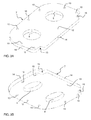
Fig. 5A is an enlarged view of a portion inFig. 2 to illustrate a set of design parameters for the mounting plate included in the plate heat exchanger,Fig. 5B is a view corresponding toFig. 5A to illustrate design parameters in an alternative configuration, andFigs 5C-5D are perspective views from above and below, respectively, of the portion shown inFig. 5A . -
Fig. 6 is a partial perspective view of a plate heat exchanger with a convex mounting plate. -
Fig. 7 is a perspective view of a sealing plate included in the plate heat exchanger ofFig. 1 . -
Fig. 8 is a perspective view of a reinforcement plate included in the plate heat exchanger ofFig. 1 . -
Figs 9A-9B are partial plan views of a plate heat exchanger with concave mounting plates of alternative configuration. - Embodiments of the present invention relate to configurations of a mounting structure on a plate heat exchanger. Corresponding elements are designated by the same reference numerals.
-
Figs 1-2 disclose an embodiment of aplate heat exchanger 1 according to the invention. Theplate heat exchanger 1 comprises a plurality of plates which are stacked one on top of the other to form aplate package 2. Theplate package 2 may be of any conventional design. Generally theplate package 2 comprises a plurality ofheat exchanger plates 3 with corrugated heat transfer portions that define flow passages (Internal channels) for a first and second fluid between theheat exchanger plates 3 such that heat is transferred through the heat transfer portions from one fluid to the other. Theheat exchanger plates 3 may be single-walled or double-walled. Theheat exchanger plates 3 are only schematically indicated inFig. 1 , since they are well-known to the person skilled in the art and their configuration is not essential for the present invention. Theplate package 2 has the general shape of a rectangular cuboid, albeit with rounded corners. Other shapes are conceivable. Generally, theplate package 2 defines a surroundingexternal wall 4 which extends in a height or axial direction A between a top axial end and a bottom axial end. Thewall 4 has a given perimeter or contour at its bottom axial end. In the illustrated example, thewall 4 has essentially the same contour along its extent in the axial direction A. The bottom axial end of theplate package 2 comprises or is provided with an essentially planar end surface 5 (Fig. 2 ), which may but need not conform to the contour of thewall 4 at the bottom axial end. Theend surface 5 extends in a lateral plane. Generally, theplate package 2, and theend surface 5, extends between two longitudinal ends in a longitudinal direction L and between two transverse ends in a transverse direction T (Fig. 2 ). - Although not shown on the drawings, the
heat transfer plates 3 have in their corner portions through-openings, which form inlet channels and outlet channels in communication with the flow passages for the first fluid and the second fluid. These inlet and outlet channels open in theend surface 5 of theplate package 2 to define separate portholes for inlet and outlet of the first and second fluids, respectively. In the illustrated example, theend surface 5 has four portholes 6 (Fig. 2 ). - The
plate package 2 is permanently connected to two identical (in this example) mountingplates 7, which are arranged on a respective end portion of theend surface 5. The mountingplates 7 are thereby separated in the longitudinal direction L, leaving a space free of material beneath the center portion of theplate package 2. Compared to using a single mounting plate that extends beneath theentire plate package 2, the illustrated configuration saves weight and material of theheat exchanger 1, and thereby also cost. Each mountingplate 7 has two through-holes 8 which are mated with a respective pair of theportholes 6 of theplate package 2 to define inlet and outlet ports of theheat exchanger 1. The mountingplates 7 are configured for attaching theheat exchanger 1 to an external suspension structure (not shown) such that the inlet and outlet ports mate with corresponding supply ports for the first and second medium on the external structure. Optionally, one or more seals (not shown) may be provided in the interface between the mountingplate 7 and the external structure. - Each mounting
plate 7 defines a mountingflange 9 that projects from thewall 4 and extends around the longitudinal end of theplate package 2.Bores 10 are provided in the mountingflange 9 as a means for fastening theheat exchanger 1 to the external structure. Threaded fasteners or bolts, for example, may be introduced into thebores 10 for engagement with corresponding bores in the external structure. - The
plate package 2 and the mountingplates 7 are made of metal, such as stainless steel or aluminum. All the plates in theheat exchanger 1 are permanently connected to each other, preferably through melting of a metallic material, such as brazing, welding or a combination of brazing and welding. The plates in theplate package 2 may alternatively be permanently connected by gluing. - The mounting
plates 7 are dimensioned, with respect to material, thickness and extent in the longitudinal and transverse directions, so as to have an adequate strength and stiffness to the static load that is applied to the mountingplates 7 when fastened on the external structure. The static load, which tends to deform the mountingplates 7, may originate from a combination of the weight of theheat exchanger 1, internal pressure applied by the media in theheat exchanger 1 and transferred to the mountingplates 7, and compression forces applied to the mountingplates 7, e.g. at the above-mentioned seals, via the fasteners and thebores 10. This static load tend to deform the mountingplates 7. As seen inFigs 1-3 , the mountingplates 7 are generally designed to have a significant thickness. As a non-limiting example, the thickness may be 15-40 mm. The bottom of theplate package 2, on the other hand, is normally made of much thinner material. - If the
heat exchanger 1 is installed in an environment where vibrations are transferred to the mountingplate 7 via the external structure, theheat exchanger 1 also needs to be designed to account for the mechanical stresses caused by the cyclic loading of the vibrations, i.e. cyclic stresses. For example, such vibrations occur for heat exchangers that are mounted in vehicles, such as cars, trucks and ships. In one non-limiting example, theheat exchanger 1 is an oil cooler for an engine. When cyclic stresses are applied to a material, even though the stresses do not cause plastic deformation, the material may fail due to fatigue especially in local regions with high stress concentration. The use of stiffthick mounting plates 7 connected to aplate package 2 with a relatively thin bottom is likely to lead to high concentrations of cyclic stress at the interface between the mountingplates 7 and theplate package 2, and possibly also within theplate package 2. - Embodiments of the present invention are designed to counteract stress concentration that may lead to fatigue failure. To this end, the mounting
plates 7 have a perimeter withconcave portions 15, which are located so as to intersect the perimeter of the surroundingwall 4 of theplate package 2, as seen in the normal direction to theend surface 5. As used herein, the "perimeter" designates the outer contour as seen in plan view. In the plan view ofFig. 2 , intersection points 11 between the perimeters of the mountingplates 7 and thewall 4 are indicated by black dots. By providing theconcave portions 15 at the intersection points 11, the perimeter of the mountingplate 7 is given an increased extent in a region at and around the intersection points 11. The increased extent favors distribution of stress. Furthermore, theconcave portions 15 generally define more favorable angles between the perimeter of the mountingplate 7 and the surroundingwall 4 for counteracting stress concentration. -
Figs 3A-3B illustrate a mountingplate 7 in more detail. The mountingplate 7 has essentially planar top andbottom surfaces top surface 12 forms an engagement surface to be permanently connected to theend surface 5 on theplate package 2, and thebottom surface 13 forms an engagement surface to be applied and fixed to the external supporting structure. The through-holes 8 and bores 10 are formed to extend between the top andbottom surfaces plate 7, the top and bottom surfaces are connected by aperipheral edge surface 14. Theedge surface 14 is essentially planar and right-angled to the top andbottom surfaces plate 7. - The mounting
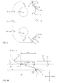
plate 7 is generally elongated and has a concave shape, as seen in plan view. The term "concave shape" is used in its ordinary meaning to denote a shape that contains at least one portion that bends inwards, i.e. a concave portion. A concave shape is also known as a "non-convex shape". In a geometric sense, as shown inFig. 4 , each of theconcave portions 15 extends between two well-defined limit points C1, C2. The limit points C1, C2 are located where a straight mathematical (fictitious) line ML touches the perimeter of the mountingplate 7 so as to bridge theconcave portion 15. The respective line ML thus intersects the perimeter of the mountingplate 7 at only two locations (at C1 and C2) and is spaced from the perimeter of the mountingplate 7 between these two locations. As seen inFig. 4 , the respectiveconcave portion 15 extends to an inward corner between a distal outward corner, containing the limit point C1, and a proximate outward corner, containing the limit point C2. - In plan view, the
concave portions 15 of the mountingplate 7 are connected by an essentially straight contour line that extends across theend surface 5. This design is selected to minimize the width of the mountingplates 7 in the longitudinal direction L (Fig. 2 ). Other designs are conceivable. -
Fig. 5A is taken within the dashedrectangle 5A in the bottom plan view ofFig. 2 and illustrates a region of overlap between the perimeter of the mountingplate 7 and theplate package 2 near the surroundingwall 4. Thewall 4 is hidden from view by intermediate structures (see below), but its location is indicated by a dashed line. In the illustrated example, the inward corner follows an arc of a circle with radius R1. Similarly, the proximate outward corner, which is located on and attached to theend surface 5, follows an arc of a circle with radius R2. In the illustrated example, the inward corner and the proximate outward corner are connected by an essentially straight (linear) line portion. - Simulations indicate that a more uniform distribution of stress is favored by constraining the angles between the
concave portion 15 and the surroundingwall 4 where theconcave portion 15 overlaps the plate package, i.e. at and within the perimeter of the surroundingwall 4. The present Applicant has identified a constraint that may be applied to a subset of theconcave portion 15 that overlaps the plate package. This subset is denoted "constrained perimeter" in the following. In the example ofFig. 5A , the constrained perimeter extends from a starting point P1, which coincides with theintersection point 11, to a well-defined end point P2. Along the extent of the constrained perimeter, the local inclination of the perimeter is constrained to be within a predefined angular range. The local inclination is given by the tangent to the perimeter at each individual location on the perimeter, as seen in a normal direction to theend surface 5. The angular range is given by a maximum design angle αmax, which is defined with respect to the longitudinal direction L (i.e. the direction of the nearby wall 4). The angular range thus extends from -αmax to αmax. The end point P2 is given by the location along the perimeter where the local inclination exceeds the maximum design angle αmax, as indicated inFig. 5A . The constrained perimeter has an overall extent ΔL in the longitudinal direction L and an overall extent ΔT in the transverse direction T. The present Applicant has found that a favorable distribution of stress is achieved by designing theconcave portion 15 with a constrained perimeter such that ΔT/ΔL ≤ 2. For example, it may be desirable to configure theconcave portion 15 with ΔT/ΔL ≤ 1.5, ΔT/ΔL ≤ 1 or ΔT/ΔL ≤ 0.5. - Although not clearly shown in
Fig. 5A , the mountingplate 7 abuts on and is attached to theend surface 5 along the entire extent of the constrained perimeter. This configuration may improve the stability and durability of the heat exchanger. - It is currently believed that a favorable distribution of stress is achieved with the maximum design angle αmax set to a value of about 65°, although other values are conceivable. It should also be noted that the maximum design angle αmax generally defines the end point P2, and that the local inclination may be significantly smaller than αmax along a significant portion of the constrained perimeter. Such an example is seen in
Fig. 5A . Thus, a further design criterion may be applied to restrict the local inclination to a main angle αmain for at least 30%, and typically at least 50%, of the constrained perimeter. For example, the main angle αmain may set the inclination of the linear portion that connects circular arcs (defined by R1, R2 inFig. 5A ). The main angle αmain is smaller than the maximum design angle αmax and may e.g. be set to approximately 55°, 45°, 35°, 25°, 15° or 5°. The main angle αmain may even be 0, which means that the constrained perimeter would partially extend in alignment with thewall 4, i.e. along the dashedline 4 inFig. 5A . - It is realized that the radii R1, R2 of the circular arcs, as well as the extent of the line portion (if present) that connects the circular arcs, may be set so as to fulfill the above-described design criteria. It should also be noted that even if an implementation with circular arcs and an essentially linear portion that connects the circular arcs (as in
Figs 5A-5B ) may simplify manufacture of the mountingplates 7, other configurations of the inward and outward corners are conceivable. - It is currently believed that the stress distribution is favored by locating the starting point P1 of the constrained perimeter at the
intersection point 11, as shown inFig. 5A . However, this means that the local inclination of the perimeter at theintersection point 11 should not exceed the maximum design angle αmax. However, it is conceivable that other design considerations call for a greater freedom to locate the constrained perimeter. Simulations indicate that a comparable stress distribution is achieved even if the starting point P1 is shifted from theintersection point 11.Fig. 5B illustrates an example of aconcave portion 15 that extends across thewall 4 at right angles, whereby the starting point P1 is set to the location where the local inclination equals the maximum design angle αmax. This means that the starting point P1 is shifted from theintersection point 11 in both the transverse direction T and the longitudinal direction L. According to one design criterion, the transverse spacing δT between the starting point P1 and theintersection point 11 fulfills δT/ΔL ≤ 0.2, and preferably δT/ΔL ≤ 0.1. In a practical implementation, this may correspond to a transverse spacing δT of less than about 5 mm. - It should be noted, though, that even if it is possible for the
concave portion 15 to intersect thewall 4 at right angles, the distribution of stress is generally favored by a non-perpendicular intersection, e.g. as shown inFig. 5A . - For reference, it may be noted that the configuration in
Fig. 5A is designed with αmain = 15°, ΔT/ΔL ≤ = 4.75/12.21 = 0.39, δT = 0, R1 = 10 mm, R2 = 4 mm. The configuration inFig. 5B is designed with αmain = 15°, ΔT/ΔL ≤ = 8.6/18 = 0.48, δT/ΔL = 2/18 = 0.11, R1 = 1 mm, R2 = 10 mm. -
Figs 5C-5D are perspective views from above and below, respectively, of the juncture between the mountingplate 7 and theplate package 2 for the embodiment inFig. 5A , whereFig. 5C is taken within the dashed rectangle 5C inFig. 1 . In this particular example, further structures are located in the interface between the plate package and the mountingplate 7, for the purpose of improving the stability and durability of theheat exchanger 1. These structures include a sealingplate 21 which is connected to the stack ofheat exchanger plates 3 to define a bottom surface of theplate package 2. The sealingplate 21, as shown inFig. 7 , is generally planar and has through-holes 22 at its corners to be mated with corresponding through-holes in theheat exchanger plates 3. The perimeter of the sealingplate 21 is bent upwards to form a surroundingflange 23 which adapted to abut on and be fixed to a corresponding flange of an overlying heat exchanger plate, as is known in the art. The material thickness of the sealingplate 21 typically exceeds the material thickness of the heat exchanger plates, and thus the surroundingflange 23 may project slightly beyond the perimeter of the surrounding wall 4 (by 1-2 mm). This is illustrated in the bottom plan views ofFigs 5A-5B . In certain embodiments, the mountingplates 7 may be directly attached to the sealingplate 21. In such embodiments, the sealingplate 21 is an end plate that defines theend surface 5. - However, in the illustrated embodiment, an
additional plate 24 is attached intermediate the sealingplate 21 and the mountingplate 7 for the purpose of reinforcing the bottom surface of theplate package 2. Thus, theend surface 5 is defined by this additional reinforcement or supportingplate 24. The use of such areinforcement plate 24 may be advantageous when the working pressure of one or both of the media conveyed through theheat exchanger 1 is high or when the working pressure for one or both of the media varies over time. Thereinforcement plate 24, which is shown in greater detail inFig. 8 , has a uniform thickness and defines through-holes 25 which are matched to the portholes in theplate package 2. The perimeter of thereinforcement plate 24 may be essentially level with the perimeter of the sealingplate 21 or the perimeter of thewall 4 of theplate package 2. However, in the illustrated example, thereinforcement plate 24 is adapted to locally project from the perimeter of thewall 4. Specifically, thereinforcement plate 24 is provided withcutouts 26 that are located to extend in the longitudinal direction between the intersection points 11 on a respective transverse side of theplate package 2 so as to be essentially level with theaxial wall 4. InFigs 5A-5B , however, thecutouts 26 are slightly displaced inwardly from theaxial wall 4. The longitudinal end points of thecutouts 26 define arespective transition 27 to a projectingtab portion 28. In the example ofFigs 5C-5D , thetransitions 27 are located to overlap the perimeter of the mountingplate 7 in proximity to the intersection points 11 and are shaped to be non-perpendicular to the perimeter of the mountingplate 7 at the overlap, as seen in a direction towards the bottom of theheat exchanger 1. This configuration of thereinforcement plate 24 will locally decrease the stress in thereinforcement plate 24 at the intersection points 11. Thetransitions 27 may e.g. form a bevel or a curve from thecutout 26 to thetab 28. InFigs 5C-5D , thetransitions 27 are further configured to essentially co-extend with perimeter of the mountingplate 7 at the overlap. Further, as seen inFigs 5C-5D , thetab portions 28 protrude from theplate package 2 to essentially co-extend with and abut against arespective mounting plate 7. This has been found to result in a favorable distribution of stress between the mountingplate 7, thereinforcement plate 24 and the sealingplate 21 especially at the corners of theplate package 2. It will also increase the strength of the joint between thereinforcement plate 24 and the mountingplate 7 due to the increased contact area between them. In an alternative implementation, not shown, thereinforcement plate 24 projects from theplate package 2 around its entire perimeter except for small notches that are located in the proximity of the intersection points 11 to providetransitions 27 that are appropriately shaped to be non-perpendicular to, and preferably co-extending with, the perimeter of the mountingplate 7. - The design of the mounting
plate 7, and thereinforcement plate 24 if present, may be optimized based on the general principles outlined above, by simulating the distribution of stress in the heat exchanger structure. Such simulations may serve to adapt one or more of the thickness of the mountingplates 7, the width of the mountingplate 7 in the longitudinal direction L, the shape and location of theconcave portions 15, as well as further design parameters for theconcave portions 15, such as the extents ΔL, ΔT (for a given αmax), the transverse spacing δT, the radii R1, R2, and the main angle αmain. The simulations may be based on any known technique for numerical approximation of stress, such as the finite element method, the finite difference method, and the boundary element method. - A few non-limiting examples of alternative configurations of the
concave portion 15 is shown inFigs 9A-9B . The configuration inFig. 9A is designed with αmain = 6°, ΔT/ΔL ≤ = 10.4/29.6 = 0.35, δT = 0, R1 = 10 mm, R2 = 15 mm. The configuration inFig. 9B is designed with αmain = 60°, ΔT/ΔL ≤ = 1.7, δT = 0, R1 = 10 mm, R2 = 15 mm. - A simulation of the stress distribution within the structure in
Figs 5C-5D , for one specific vibration load condition, indicates that stresses are well-distributed without any significant peaks in the interface between thereinforcement plate 24 and the sealingplate 21. For this particular simulation, the maximum stress levels are distributed along arrow L1, which is co-located with the starting point P1 (Fig. 5A ). Here, the stress values are approximately 80 N/mm2 (MPa). The simulation also indicates that stresses are equally well-distributed in the interface between the mountingplate 7 and thereinforcement plate 24, where maximum stress levels of approximately 50 N/mm2 are distributed along arrow L2 inFig. 5D . Incidentally, the arrow L2 is co-located with the end point P2. Corresponding simulations for the structure inFig. 9A indicates corresponding maximum stress levels with a similar distribution. Simulations for the structure inFig. 9B indicate maximum stress levels of approximately 110 N/mm2 around the starting point P1 and approximately 60 N/mm2 around the end point P2. For comparison, the stress distribution has also been simulated, for the same vibration load condition, within a heat exchanger provided with aconvex mounting plate 7, i.e. a mountingplate 7 without concave portions, as shown inFig. 6 . In this example, thereinforcement plate 24 has the same extension as the sealingplate 21. The simulation indicated a significant stress concentration at the juncture of the mountingplate 7 and thereinforcement plate 24, with a maximum stress value of about 310 N/mm2 in region L3. - It should be understood that the design of the mounting
plates 7 is subject to several design considerations. For example, the width of the mountingplates 7 in the longitudinal direction L may be set to minimize weight and/or cost of the heat exchanger. Such a constraint may also limit the available width W of theconcave portion 15 in the longitudinal direction L. The width W is generally indicated inFigs 9A-9B . In principle, the width W should be as long as possible so as to distribute stress over a longer perimeter. As noted, the width W is typically limited in practice. The above-described design criteria stipulate that ΔT/ΔL ≤ 2 for effective suppression of stress concentration. This does not necessarily mean that it is optimal to minimize ΔT/ΔL. Instead, the design parameters, and thus ΔT/ΔL, may be optimized to minimize the maximum stress values for any given width W. The structures inFigs 9A-9B have been optimized in this way. Thus, the maximum stress values are minimized at ΔT/ΔL ≤ = 0.35 for the structure inFig. 9A , and at ΔT/ΔL ≤ = 1.7 for the structure inFig. 9B . Generally, the optimum ΔT/ΔL ≤ increases with decreasing width W. This can be understood by considering that although the stresses at the starting point P1 will decrease with increasing width W and with decreasing ΔT (i.e. as the constricted perimeter is being more parallel to the longitudinal direction L), significant stresses are formed at and around the end point P2 if located close to the surroundingwall 4, when the width W is limited. Thus, the possible optimization with respect to ΔT/ΔL ≤ is aimed at balancing the stresses formed at the starting point P1 and the stresses formed at the end point P2. Generally, with decreasing width W, the optimum is found by moving the end point P2 away from thewall 4, i.e. by increasing ΔT, e.g. by increasing the main angle αmain and/or the radius R2. The foregoing discussion is only given to explain the relevance of the ratio ΔT/ΔL ≤ and does not imply that the design parameters of theconcave portion 15 need to be optimized for a specific width W. - While the invention has been described in connection with what is presently considered to be the most practical and preferred embodiments, it is to be understood that the invention is not to be limited to the disclosed embodiments, but on the contrary, is intended to cover various modifications and equivalent arrangements included within the spirit and the scope of the appended claims.
- For example, the
edge surface 14 may have any shape and angle to the top andbottom surfaces plate 7. - The
reinforcement plate 24, as described and exemplified herein, may also be installed in aplate heat exchanger 1 withconvex mounting plates 7, e.g. as shown inFig. 6 , to increase the stability and durability of theplate heat exchanger 1 and, to a certain degree, counteract stress concentration at the intersection points 11. Such areinforcement plate 24 may provide supportingflanges 28 that extend beyond the perimeter of the surroundingwall 4 and are permanently connected to thetop surface 12 of the mountingplates 7. Thereinforcement plate 24 may also define the above-describedtransitions 27, which are located to overlap the perimeter of the respective mountingplate 7 at the intersection points 11 and are shaped to be non-perpendicular to, and preferably co-extending with, the perimeter of the respective mountingplate 7 at the overlap. - As used herein, "top", "bottom", "vertical", "horizontal", etc merely refer to directions in the drawings and does not imply any particular positioning of the
heat exchanger 1. Nor does this terminology imply that the mountingplates 7 need to be arranged on any particular end of theplate package 2. Reverting toFig. 1 , the mounting plates may alternatively be arranged on the top axial end of theplate package 2 and may be permanently connected either to a sealing plate or to a reinforcement plate overlying the sealing plate. Furthermore, the mountingplates 7 may be arranged on an end of theplate package 2 that lacks portholes or on which each or at least oneporthole 6 is located intermediate the mountingplates 7.
Claims (19)
- A plate heat exchanger, comprising:a plurality of heat exchanger plates (3) which are stacked and permanently connected to form a plate package (2) that defines first and second fluid paths for a first medium and a second medium, respectively, separated by said heat exchanger plates (3), said plate package (2) defining a surrounding external wall (4) that extends in an axial direction (A) between first and second axial ends,an end plate (21; 24) permanently connected to one of the first and second axial ends so as to provide an end surface (5) that extends between first and second longitudinal ends in a lateral plane which is orthogonal to the axial direction (A), andtwo mounting plates (7) permanently connected to a respective surface portion of the end surface (5) at the first longitudinal end and the second longitudinal end, respectively, such that the mounting plates (7) are spaced from each other in a longitudinal direction (L) on the end surface (5), wherein the respective mounting plate (7) comprises opposing flat engagement surfaces (12, 13) connected by an edge portion that extends along the perimeter of the mounting plate (7),wherein the respective mounting plate (7) is arranged with one of its engagement surfaces (12, 13) permanently connected to the end surface (5), such that the perimeter of the mounting plate (7) partially extends beyond the surrounding external wall (4), so as to define a mounting flange (9), and partially extends across the end surface (5) in contact with the same within the perimeter of the surrounding external wall (4), andwherein the perimeter of the mounting plate (7) defines a concave shape comprising two concave portions (15) as seen in a normal direction to the end surface (5), the concave portions (15) being located to intersect the surrounding external wall (4) at a respective intersection point (11).
- The plate heat exchanger of claim 1, wherein a subset of the respective concave portion (15) is located at or within the surrounding external wall (4) and is non-perpendicular to the perimeter of the surrounding external wall (4) at the respective intersection point (11), as seen in the normal direction to the end surface (5).
- The plate heat exchanger of claim 2, wherein said subset of the respective concave portion (15) extends from a starting point (P1) to an end point (P2) on the concave portion (15), such that the local inclination of the concave portion, given by a tangential line, along said subset is less than a maximum design angle (αmax), and wherein the end point (P2) is located where the local inclination exceeds the maximum design angle (αmax).
- The plate heat exchanger of claim 3, wherein the maximum design angle is defined between the tangential line and the longitudinal direction (L) and has a value of approximately 65°.
- The plate heat exchanger of claim 3 or 4, wherein said subset comprises an essentially linear portion within at least 30% of said subset, said linear portion having a predefined angle (αmain), to the longitudinal direction (L), which is less that the maximum design angle (αmax).
- The plate heat exchanger of any one of claims 3-5, wherein said subset of the respective concave portion (15) has a first extent (ΔL) in the longitudinal direction (L) and a second extent (ΔT) in a transverse direction (T), which is orthogonal to the longitudinal direction (L) in the plane of the mounting plate (7), wherein the ratio of the second extent (ΔT) to the first extent (ΔL) is equal to or less than approximately 2, and preferably equal to or less than approximately 1 or approximately 0.5.
- The plate heat exchanger of any one of claims 3-6, wherein the predefined starting point (P1) of said subset is located within a maximum design distance (δT), in the transverse direction (T), from the respective intersection point (11), wherein the maximum design distance (δT) is 20% of the first extent (ΔL).
- The plate heat exchanger of any one of claims 3-7, wherein the starting point (P1) essentially coincides with the respective intersection point (11).
- The plate heat exchanger of any preceding claim, wherein said end point (P2) is located on an outward corner of the mounting plate (7), said outward corner being defined by a second radius (R2).
- The plate heat exchanger of any preceding claim, wherein the perimeter of the mounting plate (7) is non-perpendicular to the perimeter of the surrounding external wall (4) at the respective intersection point (11), as seen in the normal direction to the end surface (5).
- The plate heat exchanger of any preceding claim, wherein the mounting plate (7) abuts on and is permanently connected to the end surface (5) along said subset of the concave portion (15).
- The plate heat exchanger of any preceding claim, wherein the respective concave portion (15) comprises an inward corner defined by a first radius (R1), said inward corner intersecting the surrounding external wall (4) at the intersection point (11), as seen in the direction normal to the end surface (5).
- The plate heat exchanger of any preceding claim, wherein the respective concave portion (15) extends between two limit points (C1, C2) on the perimeter of the mounting plate (7), said limit points (C1, C2) being defined by a mathematical line (ML) which intersects the perimeter of the mounting plate (7) only at the limit points (C1, C2) and which extends beyond the perimeter of the mounting plate (7) intermediate the limit points (C1, C2), as seen in the direction normal to the end surface (5).
- The plate heat exchanger of any preceding claim, wherein the end plate (21) is a sealing plate which is permanently and sealingly connected to one of the heat exchanger plates (3) at one of said first and second axial ends.
- The plate heat exchanger of any one of claims 1-13, wherein the end plate (24) is a reinforcement plate (24) which is permanently connected to a sealing plate (21) on the plate package (2), wherein the end plate (24) has at least two supporting flanges (28) that extend beyond the perimeter of the surrounding external wall (4) so as to abut on the mounting flange (9) defined by the respective mounting plate (7).
- The plate heat exchanger of claim 15, wherein the end plate (24) comprises, along its perimeter and as seen in the normal direction of the end surface (5), concave or beveled surfaces (27) adjacent to the supporting flanges (28), wherein the concave or beveled surfaces (27) are located to overlap the perimeter of the respective mounting plate (7) at the intersection points (11), and wherein the respective concave or beveled surface (27) is non-perpendicular to, and preferably co-extending with, the perimeter of the mounting plate (7) at the overlap, as seen in the normal direction to the end surface (5).
- The plate heat exchanger of any preceding claim, wherein at least one of the mounting plates (7) defines at least one through hole (8) that extends between the engagement surfaces (12, 13) and is aligned with a corresponding through hole (22; 25) defined in the end plate (21; 24) and an internal channel defined in the plate package (2), so as to form an inlet or an outlet for the first or the second medium.
- The plate heat exchanger of any preceding claim, wherein the mounting flange (9) comprises a plurality of mounting holes (10) adapted to receive bolts or pins for fastening the plate heat exchanger.
- The plate heat exchanger of any preceding claim, wherein the heat exchanger plates (3) are permanently joined to each other through melting of metallic material.
Priority Applications (4)
| Application Number | Priority Date | Filing Date | Title |
|---|---|---|---|
| EP13198883.4A EP2886996B1 (en) | 2013-12-20 | 2013-12-20 | Plate heat exchanger with mounting flange |
| SE1650782A SE1650782A1 (en) | 2013-12-20 | 2014-12-11 | Plate heat exchanger with mounting flange |
| PCT/EP2014/077423 WO2015091215A1 (en) | 2013-12-20 | 2014-12-11 | Plate heat exchanger with mounting flange |
| TW103144274A TWI539135B (en) | 2013-12-20 | 2014-12-18 | Plate heat exchanger with mounting flange |
Applications Claiming Priority (1)
| Application Number | Priority Date | Filing Date | Title |
|---|---|---|---|
| EP13198883.4A EP2886996B1 (en) | 2013-12-20 | 2013-12-20 | Plate heat exchanger with mounting flange |
Publications (2)
| Publication Number | Publication Date |
|---|---|
| EP2886996A1 true EP2886996A1 (en) | 2015-06-24 |
| EP2886996B1 EP2886996B1 (en) | 2016-07-13 |
Family
ID=49841588
Family Applications (1)
| Application Number | Title | Priority Date | Filing Date |
|---|---|---|---|
| EP13198883.4A Active EP2886996B1 (en) | 2013-12-20 | 2013-12-20 | Plate heat exchanger with mounting flange |
Country Status (4)
| Country | Link |
|---|---|
| EP (1) | EP2886996B1 (en) |
| SE (1) | SE1650782A1 (en) |
| TW (1) | TWI539135B (en) |
| WO (1) | WO2015091215A1 (en) |
Citations (8)
| Publication number | Priority date | Publication date | Assignee | Title |
|---|---|---|---|---|
| US20050121182A1 (en) * | 2003-10-10 | 2005-06-09 | Jurgen Hummel | Heat exchanger, especially oil cooler |
| DE102007008459A1 (en) * | 2006-02-22 | 2007-12-13 | Behr Gmbh & Co. Kg | Stacked plate heat-exchanger, has reinforcement disk connected with base plate, where baseplate formed as single piece with reinforcement disk is connected at base disk with defined reinforcement structure |
| CN201285244Y (en) * | 2008-10-21 | 2009-08-05 | 宁波路润冷却器制造有限公司 | Plate type finned oil cooler |
| US20100258095A1 (en) | 2009-03-13 | 2010-10-14 | Christian Saumweber | Heat exchanger |
| WO2011009412A1 (en) * | 2009-07-23 | 2011-01-27 | Caterpillar Inc. | Heat exchanger assembly and machine using the same |
| US8181695B2 (en) | 2005-10-05 | 2012-05-22 | Dana Canada Corporation | Reinforcement for dish plate heat exchangers |
| DE202012007775U1 (en) * | 2012-04-26 | 2012-10-15 | Dana Canada Corporation | Heat exchanger with adapter module |
| DE102011080824A1 (en) * | 2011-08-11 | 2013-02-14 | Mahle International Gmbh | Plate heat exchanger |
-
2013
- 2013-12-20 EP EP13198883.4A patent/EP2886996B1/en active Active
-
2014
- 2014-12-11 WO PCT/EP2014/077423 patent/WO2015091215A1/en not_active Ceased
- 2014-12-11 SE SE1650782A patent/SE1650782A1/en not_active Application Discontinuation
- 2014-12-18 TW TW103144274A patent/TWI539135B/en active
Patent Citations (8)
| Publication number | Priority date | Publication date | Assignee | Title |
|---|---|---|---|---|
| US20050121182A1 (en) * | 2003-10-10 | 2005-06-09 | Jurgen Hummel | Heat exchanger, especially oil cooler |
| US8181695B2 (en) | 2005-10-05 | 2012-05-22 | Dana Canada Corporation | Reinforcement for dish plate heat exchangers |
| DE102007008459A1 (en) * | 2006-02-22 | 2007-12-13 | Behr Gmbh & Co. Kg | Stacked plate heat-exchanger, has reinforcement disk connected with base plate, where baseplate formed as single piece with reinforcement disk is connected at base disk with defined reinforcement structure |
| CN201285244Y (en) * | 2008-10-21 | 2009-08-05 | 宁波路润冷却器制造有限公司 | Plate type finned oil cooler |
| US20100258095A1 (en) | 2009-03-13 | 2010-10-14 | Christian Saumweber | Heat exchanger |
| WO2011009412A1 (en) * | 2009-07-23 | 2011-01-27 | Caterpillar Inc. | Heat exchanger assembly and machine using the same |
| DE102011080824A1 (en) * | 2011-08-11 | 2013-02-14 | Mahle International Gmbh | Plate heat exchanger |
| DE202012007775U1 (en) * | 2012-04-26 | 2012-10-15 | Dana Canada Corporation | Heat exchanger with adapter module |
Also Published As
| Publication number | Publication date |
|---|---|
| WO2015091215A1 (en) | 2015-06-25 |
| EP2886996B1 (en) | 2016-07-13 |
| SE1650782A1 (en) | 2016-06-03 |
| TW201525408A (en) | 2015-07-01 |
| TWI539135B (en) | 2016-06-21 |
Similar Documents
| Publication | Publication Date | Title |
|---|---|---|
| US10260822B2 (en) | Plate heat exchanger with mounting flange | |
| US8128099B2 (en) | Gasket | |
| EP1350993B1 (en) | Metallic gasket | |
| US8646517B2 (en) | Plate and gasket for plate heat exchanger | |
| CN101317069B (en) | Reinforcements for dish plate heat exchangers | |
| US8636162B2 (en) | Fuel tank shell with structural support | |
| US20180128556A1 (en) | Heat exchanger and heat exchanger tank | |
| EP3126771B1 (en) | Heat exchanger and method of making a heat exchanger | |
| CN103867334A (en) | Gasket and cylinder head gasket | |
| EP2886996B1 (en) | Plate heat exchanger with mounting flange | |
| EP2886995B1 (en) | Plate heat exchanger with mounting flange | |
| EP2626228A1 (en) | Fuel tank for vehicle | |
| CN111981877B (en) | Plate heat exchanger | |
| JP2012207727A (en) | Cylinder head gasket | |
| KR20130064207A (en) | Cross section structure for ship | |
| WO2019056114A1 (en) | Localized reinforcement of stacked dish plate heat exchangers | |
| CN107524543A (en) | Internal combustion engine | |
| JP2008111540A (en) | Cylinder head gasket |
Legal Events
| Date | Code | Title | Description |
|---|---|---|---|
| PUAI | Public reference made under article 153(3) epc to a published international application that has entered the european phase |
Free format text: ORIGINAL CODE: 0009012 |
|
| 17P | Request for examination filed |
Effective date: 20140312 |
|
| AK | Designated contracting states |
Kind code of ref document: A1 Designated state(s): AL AT BE BG CH CY CZ DE DK EE ES FI FR GB GR HR HU IE IS IT LI LT LU LV MC MK MT NL NO PL PT RO RS SE SI SK SM TR |
|
| AX | Request for extension of the european patent |
Extension state: BA ME |
|
| GRAP | Despatch of communication of intention to grant a patent |
Free format text: ORIGINAL CODE: EPIDOSNIGR1 |
|
| INTG | Intention to grant announced |
Effective date: 20160302 |
|
| GRAS | Grant fee paid |
Free format text: ORIGINAL CODE: EPIDOSNIGR3 |
|
| GRAA | (expected) grant |
Free format text: ORIGINAL CODE: 0009210 |
|
| AK | Designated contracting states |
Kind code of ref document: B1 Designated state(s): AL AT BE BG CH CY CZ DE DK EE ES FI FR GB GR HR HU IE IS IT LI LT LU LV MC MK MT NL NO PL PT RO RS SE SI SK SM TR |
|
| REG | Reference to a national code |
Ref country code: GB Ref legal event code: FG4D |
|
| REG | Reference to a national code |
Ref country code: AT Ref legal event code: REF Ref document number: 812696 Country of ref document: AT Kind code of ref document: T Effective date: 20160715 Ref country code: CH Ref legal event code: EP |
|
| REG | Reference to a national code |
Ref country code: IE Ref legal event code: FG4D |
|
| REG | Reference to a national code |
Ref country code: DE Ref legal event code: R096 Ref document number: 602013009314 Country of ref document: DE |
|
| REG | Reference to a national code |
Ref country code: SE Ref legal event code: TRGR |
|
| REG | Reference to a national code |
Ref country code: LT Ref legal event code: MG4D |
|
| REG | Reference to a national code |
Ref country code: NL Ref legal event code: MP Effective date: 20160713 |
|
| REG | Reference to a national code |
Ref country code: AT Ref legal event code: MK05 Ref document number: 812696 Country of ref document: AT Kind code of ref document: T Effective date: 20160713 |
|
| PG25 | Lapsed in a contracting state [announced via postgrant information from national office to epo] |
Ref country code: HR Free format text: LAPSE BECAUSE OF FAILURE TO SUBMIT A TRANSLATION OF THE DESCRIPTION OR TO PAY THE FEE WITHIN THE PRESCRIBED TIME-LIMIT Effective date: 20160713 Ref country code: IT Free format text: LAPSE BECAUSE OF FAILURE TO SUBMIT A TRANSLATION OF THE DESCRIPTION OR TO PAY THE FEE WITHIN THE PRESCRIBED TIME-LIMIT Effective date: 20160713 Ref country code: IS Free format text: LAPSE BECAUSE OF FAILURE TO SUBMIT A TRANSLATION OF THE DESCRIPTION OR TO PAY THE FEE WITHIN THE PRESCRIBED TIME-LIMIT Effective date: 20161113 Ref country code: FI Free format text: LAPSE BECAUSE OF FAILURE TO SUBMIT A TRANSLATION OF THE DESCRIPTION OR TO PAY THE FEE WITHIN THE PRESCRIBED TIME-LIMIT Effective date: 20160713 Ref country code: NL Free format text: LAPSE BECAUSE OF FAILURE TO SUBMIT A TRANSLATION OF THE DESCRIPTION OR TO PAY THE FEE WITHIN THE PRESCRIBED TIME-LIMIT Effective date: 20160713 Ref country code: LT Free format text: LAPSE BECAUSE OF FAILURE TO SUBMIT A TRANSLATION OF THE DESCRIPTION OR TO PAY THE FEE WITHIN THE PRESCRIBED TIME-LIMIT Effective date: 20160713 Ref country code: RS Free format text: LAPSE BECAUSE OF FAILURE TO SUBMIT A TRANSLATION OF THE DESCRIPTION OR TO PAY THE FEE WITHIN THE PRESCRIBED TIME-LIMIT Effective date: 20160713 Ref country code: NO Free format text: LAPSE BECAUSE OF FAILURE TO SUBMIT A TRANSLATION OF THE DESCRIPTION OR TO PAY THE FEE WITHIN THE PRESCRIBED TIME-LIMIT Effective date: 20161013 |
|
| PG25 | Lapsed in a contracting state [announced via postgrant information from national office to epo] |
Ref country code: ES Free format text: LAPSE BECAUSE OF FAILURE TO SUBMIT A TRANSLATION OF THE DESCRIPTION OR TO PAY THE FEE WITHIN THE PRESCRIBED TIME-LIMIT Effective date: 20160713 Ref country code: PT Free format text: LAPSE BECAUSE OF FAILURE TO SUBMIT A TRANSLATION OF THE DESCRIPTION OR TO PAY THE FEE WITHIN THE PRESCRIBED TIME-LIMIT Effective date: 20161114 Ref country code: PL Free format text: LAPSE BECAUSE OF FAILURE TO SUBMIT A TRANSLATION OF THE DESCRIPTION OR TO PAY THE FEE WITHIN THE PRESCRIBED TIME-LIMIT Effective date: 20160713 Ref country code: LV Free format text: LAPSE BECAUSE OF FAILURE TO SUBMIT A TRANSLATION OF THE DESCRIPTION OR TO PAY THE FEE WITHIN THE PRESCRIBED TIME-LIMIT Effective date: 20160713 Ref country code: BE Free format text: LAPSE BECAUSE OF FAILURE TO SUBMIT A TRANSLATION OF THE DESCRIPTION OR TO PAY THE FEE WITHIN THE PRESCRIBED TIME-LIMIT Effective date: 20160713 Ref country code: AT Free format text: LAPSE BECAUSE OF FAILURE TO SUBMIT A TRANSLATION OF THE DESCRIPTION OR TO PAY THE FEE WITHIN THE PRESCRIBED TIME-LIMIT Effective date: 20160713 Ref country code: GR Free format text: LAPSE BECAUSE OF FAILURE TO SUBMIT A TRANSLATION OF THE DESCRIPTION OR TO PAY THE FEE WITHIN THE PRESCRIBED TIME-LIMIT Effective date: 20161014 |
|
| REG | Reference to a national code |
Ref country code: DE Ref legal event code: R026 Ref document number: 602013009314 Country of ref document: DE |
|
| PLBI | Opposition filed |
Free format text: ORIGINAL CODE: 0009260 |
|
| PG25 | Lapsed in a contracting state [announced via postgrant information from national office to epo] |
Ref country code: RO Free format text: LAPSE BECAUSE OF FAILURE TO SUBMIT A TRANSLATION OF THE DESCRIPTION OR TO PAY THE FEE WITHIN THE PRESCRIBED TIME-LIMIT Effective date: 20160713 Ref country code: EE Free format text: LAPSE BECAUSE OF FAILURE TO SUBMIT A TRANSLATION OF THE DESCRIPTION OR TO PAY THE FEE WITHIN THE PRESCRIBED TIME-LIMIT Effective date: 20160713 |
|
| 26 | Opposition filed |
Opponent name: MAHLE INTERNATIONAL GMBH Effective date: 20170411 |
|
| PLAX | Notice of opposition and request to file observation + time limit sent |
Free format text: ORIGINAL CODE: EPIDOSNOBS2 |
|
| PG25 | Lapsed in a contracting state [announced via postgrant information from national office to epo] |
Ref country code: DK Free format text: LAPSE BECAUSE OF FAILURE TO SUBMIT A TRANSLATION OF THE DESCRIPTION OR TO PAY THE FEE WITHIN THE PRESCRIBED TIME-LIMIT Effective date: 20160713 Ref country code: BG Free format text: LAPSE BECAUSE OF FAILURE TO SUBMIT A TRANSLATION OF THE DESCRIPTION OR TO PAY THE FEE WITHIN THE PRESCRIBED TIME-LIMIT Effective date: 20161013 Ref country code: SK Free format text: LAPSE BECAUSE OF FAILURE TO SUBMIT A TRANSLATION OF THE DESCRIPTION OR TO PAY THE FEE WITHIN THE PRESCRIBED TIME-LIMIT Effective date: 20160713 Ref country code: CZ Free format text: LAPSE BECAUSE OF FAILURE TO SUBMIT A TRANSLATION OF THE DESCRIPTION OR TO PAY THE FEE WITHIN THE PRESCRIBED TIME-LIMIT Effective date: 20160713 Ref country code: SM Free format text: LAPSE BECAUSE OF FAILURE TO SUBMIT A TRANSLATION OF THE DESCRIPTION OR TO PAY THE FEE WITHIN THE PRESCRIBED TIME-LIMIT Effective date: 20160713 |
|
| REG | Reference to a national code |
Ref country code: DE Ref legal event code: R119 Ref document number: 602013009314 Country of ref document: DE |
|
| REG | Reference to a national code |
Ref country code: CH Ref legal event code: PL |
|
| PG25 | Lapsed in a contracting state [announced via postgrant information from national office to epo] |
Ref country code: SI Free format text: LAPSE BECAUSE OF FAILURE TO SUBMIT A TRANSLATION OF THE DESCRIPTION OR TO PAY THE FEE WITHIN THE PRESCRIBED TIME-LIMIT Effective date: 20160713 |
|
| PG25 | Lapsed in a contracting state [announced via postgrant information from national office to epo] |
Ref country code: MC Free format text: LAPSE BECAUSE OF FAILURE TO SUBMIT A TRANSLATION OF THE DESCRIPTION OR TO PAY THE FEE WITHIN THE PRESCRIBED TIME-LIMIT Effective date: 20160713 |
|
| REG | Reference to a national code |
Ref country code: FR Ref legal event code: ST Effective date: 20170831 |
|
| PLBB | Reply of patent proprietor to notice(s) of opposition received |
Free format text: ORIGINAL CODE: EPIDOSNOBS3 |
|
| REG | Reference to a national code |
Ref country code: IE Ref legal event code: MM4A |
|
| PG25 | Lapsed in a contracting state [announced via postgrant information from national office to epo] |
Ref country code: LI Free format text: LAPSE BECAUSE OF NON-PAYMENT OF DUE FEES Effective date: 20161231 Ref country code: FR Free format text: LAPSE BECAUSE OF NON-PAYMENT OF DUE FEES Effective date: 20170102 Ref country code: LU Free format text: LAPSE BECAUSE OF NON-PAYMENT OF DUE FEES Effective date: 20161220 Ref country code: CH Free format text: LAPSE BECAUSE OF NON-PAYMENT OF DUE FEES Effective date: 20161231 |
|
| PG25 | Lapsed in a contracting state [announced via postgrant information from national office to epo] |
Ref country code: IE Free format text: LAPSE BECAUSE OF NON-PAYMENT OF DUE FEES Effective date: 20161220 Ref country code: DE Free format text: LAPSE BECAUSE OF NON-PAYMENT OF DUE FEES Effective date: 20170701 |
|
| PG25 | Lapsed in a contracting state [announced via postgrant information from national office to epo] |
Ref country code: HU Free format text: LAPSE BECAUSE OF FAILURE TO SUBMIT A TRANSLATION OF THE DESCRIPTION OR TO PAY THE FEE WITHIN THE PRESCRIBED TIME-LIMIT; INVALID AB INITIO Effective date: 20131220 |
|
| PG25 | Lapsed in a contracting state [announced via postgrant information from national office to epo] |
Ref country code: CY Free format text: LAPSE BECAUSE OF FAILURE TO SUBMIT A TRANSLATION OF THE DESCRIPTION OR TO PAY THE FEE WITHIN THE PRESCRIBED TIME-LIMIT Effective date: 20160713 Ref country code: MK Free format text: LAPSE BECAUSE OF FAILURE TO SUBMIT A TRANSLATION OF THE DESCRIPTION OR TO PAY THE FEE WITHIN THE PRESCRIBED TIME-LIMIT Effective date: 20160713 |
|
| GBPC | Gb: european patent ceased through non-payment of renewal fee |
Effective date: 20171220 |
|
| PG25 | Lapsed in a contracting state [announced via postgrant information from national office to epo] |
Ref country code: MT Free format text: LAPSE BECAUSE OF NON-PAYMENT OF DUE FEES Effective date: 20161220 |
|
| PG25 | Lapsed in a contracting state [announced via postgrant information from national office to epo] |
Ref country code: TR Free format text: LAPSE BECAUSE OF FAILURE TO SUBMIT A TRANSLATION OF THE DESCRIPTION OR TO PAY THE FEE WITHIN THE PRESCRIBED TIME-LIMIT Effective date: 20160713 Ref country code: AL Free format text: LAPSE BECAUSE OF FAILURE TO SUBMIT A TRANSLATION OF THE DESCRIPTION OR TO PAY THE FEE WITHIN THE PRESCRIBED TIME-LIMIT Effective date: 20160713 |
|
| PG25 | Lapsed in a contracting state [announced via postgrant information from national office to epo] |
Ref country code: GB Free format text: LAPSE BECAUSE OF NON-PAYMENT OF DUE FEES Effective date: 20171220 |
|
| PLCK | Communication despatched that opposition was rejected |
Free format text: ORIGINAL CODE: EPIDOSNREJ1 |
|
| STAA | Information on the status of an ep patent application or granted ep patent |
Free format text: STATUS: THE PATENT HAS BEEN GRANTED |
|
| APBM | Appeal reference recorded |
Free format text: ORIGINAL CODE: EPIDOSNREFNO |
|
| APBP | Date of receipt of notice of appeal recorded |
Free format text: ORIGINAL CODE: EPIDOSNNOA2O |
|
| APAH | Appeal reference modified |
Free format text: ORIGINAL CODE: EPIDOSCREFNO |
|
| APBQ | Date of receipt of statement of grounds of appeal recorded |
Free format text: ORIGINAL CODE: EPIDOSNNOA3O |
|
| REG | Reference to a national code |
Ref country code: DE Ref legal event code: R100 Ref document number: 602013009314 Country of ref document: DE |
|
| APBU | Appeal procedure closed |
Free format text: ORIGINAL CODE: EPIDOSNNOA9O |
|
| PLBN | Opposition rejected |
Free format text: ORIGINAL CODE: 0009273 |
|
| STAA | Information on the status of an ep patent application or granted ep patent |
Free format text: STATUS: OPPOSITION REJECTED |
|
| 27O | Opposition rejected |
Effective date: 20220211 |
|
| P01 | Opt-out of the competence of the unified patent court (upc) registered |
Effective date: 20230419 |
|
| PGFP | Annual fee paid to national office [announced via postgrant information from national office to epo] |
Ref country code: SE Payment date: 20251001 Year of fee payment: 13 |