EP2886980A1 - Side-by-side refrigerator - Google Patents
Side-by-side refrigerator Download PDFInfo
- Publication number
- EP2886980A1 EP2886980A1 EP13829429.3A EP13829429A EP2886980A1 EP 2886980 A1 EP2886980 A1 EP 2886980A1 EP 13829429 A EP13829429 A EP 13829429A EP 2886980 A1 EP2886980 A1 EP 2886980A1
- Authority
- EP
- European Patent Office
- Prior art keywords
- door
- door body
- pedal member
- shaft
- pedal
- Prior art date
- Legal status (The legal status is an assumption and is not a legal conclusion. Google has not performed a legal analysis and makes no representation as to the accuracy of the status listed.)
- Granted
Links
Images




Classifications
-
- E—FIXED CONSTRUCTIONS
- E05—LOCKS; KEYS; WINDOW OR DOOR FITTINGS; SAFES
- E05B—LOCKS; ACCESSORIES THEREFOR; HANDCUFFS
- E05B17/00—Accessories in connection with locks
- E05B17/0025—Devices for forcing the wing firmly against its seat or to initiate the opening of the wing
- E05B17/0033—Devices for forcing the wing firmly against its seat or to initiate the opening of the wing for opening only
-
- E—FIXED CONSTRUCTIONS
- E05—LOCKS; KEYS; WINDOW OR DOOR FITTINGS; SAFES
- E05B—LOCKS; ACCESSORIES THEREFOR; HANDCUFFS
- E05B53/00—Operation or control of locks by mechanical transmissions, e.g. from a distance
- E05B53/001—Foot-operation
-
- F—MECHANICAL ENGINEERING; LIGHTING; HEATING; WEAPONS; BLASTING
- F25—REFRIGERATION OR COOLING; COMBINED HEATING AND REFRIGERATION SYSTEMS; HEAT PUMP SYSTEMS; MANUFACTURE OR STORAGE OF ICE; LIQUEFACTION SOLIDIFICATION OF GASES
- F25D—REFRIGERATORS; COLD ROOMS; ICE-BOXES; COOLING OR FREEZING APPARATUS NOT OTHERWISE PROVIDED FOR
- F25D23/00—General constructional features
- F25D23/02—Doors; Covers
-
- F—MECHANICAL ENGINEERING; LIGHTING; HEATING; WEAPONS; BLASTING
- F25—REFRIGERATION OR COOLING; COMBINED HEATING AND REFRIGERATION SYSTEMS; HEAT PUMP SYSTEMS; MANUFACTURE OR STORAGE OF ICE; LIQUEFACTION SOLIDIFICATION OF GASES
- F25D—REFRIGERATORS; COLD ROOMS; ICE-BOXES; COOLING OR FREEZING APPARATUS NOT OTHERWISE PROVIDED FOR
- F25D2400/00—General features of, or devices for refrigerators, cold rooms, ice-boxes, or for cooling or freezing apparatus not covered by any other subclass
- F25D2400/06—Refrigerators with a vertical mullion
Definitions
- Embodiments of the present invention seek to solve at least one of the problems existing in the related art to at least some extent, or to provide a consumer with a useful commercial choice. Accordingly, an object of the present invention is to provide a side-by-side refrigerator, of which a door is easy and convenient to open.
- embodiments of the present invention provide a side-by-side refrigerator, including: a refrigerator body; a left door body and a right door body rotatably disposed on the refrigerator body; a left door member disposed on the refrigerator body and movable between a left opening position in which the left door body is opened and a left closing position in which the left door body is allowed to be closed; a right door member disposed on the refrigerator body and movable between a right opening position in which the right door body is opened and a right closing position in which the right door body is allowed to be closed; a left pedal member connected with the right door member, corresponding to the left door body in an up and down direction and movable between a left stepping position and a left lifting position, wherein when the left pedal member moves from the left lifting position to the left stepping position, the right door member is driven to move from the right closing position to the right opening position; and a right pedal member connected with the left door member, corresponding to the right door body in the up and down direction and
- the left door member and the left pedal member are adjacent to a right edge of the left door body, and the right door member and the right pedal member are adjacent to a left edge of the right door body.
- the left door member is away from a left hinge and the right door member is away from a right hinge, such that the left door member and the left pedal member can be arranged compactly, the right door member and the right pedal member can be arranged compactly and it is easy for the user to open the left door body and the right door body with less effort.
- the bracket includes: a rear frame with a L-shaped cross-section and having a first vertical portion and a first horizontal portion, and a first support plate being disposed on the first vertical portion and defining a first clamping groove and a second clamping groove; and a front frame with an inverted L-shaped cross-section and having a second vertical portion and a second horizontal portion, a second support plate being disposed on the second vertical portion and spaced from the first support plate in a right and left direction, and the second support plate defining a third clamping groove and a fourth clamping groove, in which the first shaft is pivotally fitted in the first clamping groove and the third clamping groove, the second shaft is pivotally fitted in the second clamping groove and the fourth clamping groove, a left door member window and a right door member window are formed in the second horizontal portion, a left pedal member window and a right pedal member window are formed in the second vertical portion, a free end of the left door member is extended upwards and passed through the left door member window and a free
- a left boss is disposed on a lower surface of the left door body, and the free end of the left door member is located between the left boss and a front surface of the refrigerator body;
- a right boss is disposed on a lower surface of the right door body, and the free end of the right door member is located between the right boss and the front surface of the refrigerator body. Therefore, the left door body and the right door body will not be damaged after having been opened for many times, thus increasing a working life of the left door body and the right door body, i.e., increasing a working life of the side-by-side refrigerator.
- the left pedal member and the second left door arm are adjacent to a right edge of the left door body, and the right pedal member and the second right door arm are adjacent to a left edge of the right door body.
- the left pedal member and the second left door arm are adjacent to a right edge of the left door body, and the right pedal member and the second right door arm are adjacent to a left edge of the right door body.
- the side-by-side refrigerator 1 includes a refrigerator body 100, a left door body 200, a right door body 300, a left door member 500, a right door member 600, a left pedal member 700 and a right pedal member 800.
- the user may step the right pedal member 800 with his foot to move the right pedal member from the right lifting position to the right stepping position, such that the right pedal member 800 may drive the left door member 500 to move from the left closing position to the left opening position so as to open the left door 200.
- the right pedal member 800 when the right pedal member 800 is in the right lifting position, the left door member 500 is in the left closing position and the left door 200 is closed; when the right pedal member 800 is in the right stepping position, the left door member 500 is in the left opening position and the left door 200 is open.
- the left door body 200 may be opened by stepping the right pedal member 800 and the right door body 300 may be opened by stepping the left pedal member 700, so that in the processes of opening the left door body 200 and the right door body 300, the left door body 200 and the right door body 300 will not interfere with feet or legs of the user, and thus it is easier and more convenient for the user to open the left door body 200 and the right door body 300.
- the left door body 200 may be disposed on the refrigerator body 100 via a left hinge
- the right door body 300 may be disposed on the refrigerator body 100 via a right hinge.
- the side-by-side refrigerator 1 further includes a bracket 400, in which the left door member 500, the right door member 600, the left pedal member 700 and the right pedal member 800 are disposed on the bracket 400 respectively.
- a bracket 400 By disposing the bracket 400 on the refrigerator body 100, it is easy and convenient to dispose the left door member 500, the right door member 600, the left pedal member 700 and the right pedal member 800 on the refrigerator body 100.
- the side-by-side refrigerator 1 may further includes a first shaft 900 and a second shaft 1000.
- the first shaft 900 and the second shaft 1000 may be pivotally disposed on the bracket 400 and be spaced from each other in the front and rear direction and in the up and down direction, the second shaft 1000 defines a left end connected with the left door member 500 and a right end connected with the right pedal member 800, and the first shaft 900 defines a right end connected with the right door member 600 and a left end connected with the left pedal member 700.
- antiskid stripes 1100 may be formed in an upper surface of the left pedal member 700 and may also be formed in an upper surface of the right pedal member 800, such that friction forces between the user's feet and the left pedal member 700 and between the user's feet and the right pedal member 800 can be improved, thus performing a skid resistance function and further making it easier for the user to operate.
- a space configured to receive a part of the left door member 500, a part of the right door member 600, a part of the left pedal member 700, a part of the right pedal member 800, the first shaft 900 and the second shaft 1000 is defined, such that the side-by-side refrigerator 1 has a simple and artistic appearance and the left door member 500, the right door member 600, the left pedal member 700, the right pedal member 800, the first shaft 900 and the second shaft 1000 can be protected.
- first clamping groove 414 and the second clamping groove 415 in the first support plate 412 of the rear frame 410 and defining the third clamping groove 423 and the fourth clamping groove 424 in the second support plate 422 of the front frame 420 it is much easier to dispose the first shaft 900 and the second shaft 1000 on the bracket pivotally.
- a rear end of the second horizontal portion 427 of the front frame 420 contacts with an upper end of the first vertical portion 411 of the rear frame 410, and a lower end of the second vertical portion 421 of the front frame 420 contacts with a front end of the horizontal portion 413 of the rear frame 410, and thus a chamber with a general rectangle shape is defined by the rear frame 410 with the L-shaped cross-section and the front frame 420 with the inverted L-shaped cross-section.
- the first support plate 412 is disposed on a front surface of the first vertical portion 411 of the rear frame 410 (a surface of the first vertical portion 411 close to the user) and is extended forwards.
- lower ends of the left pedal window 425 and the right pedal window 426 are open, such that it is easy to dispose the left pedal member 700 and the right pedal member 800, i.e., it is easy to dispose the left power-assisted opening mechanism and the right power-assisted opening mechanism.
- the side-by-side refrigerator 1 further includes a bottom beam cover 1200 disposed on a bottom beam 140 of the refrigerator body 100 and formed with the front frame 420 integrally.
- the bottom beam cover 1200 is formed with the front frame 420 by injection molding integrally, and thus the structural strength is improved, the producing process is simplified and the producing cost is reduced.
- the side-by-side refrigerator 1 includes a first elastic member (not shown) and a second elastic member 1300.
- the first elastic member is disposed between the left pedal member 700 and the bracket 400 and is configured to push the left pedal member 700 from the left stepping position to the left lifting position.
- the second elastic member 1300 is disposed between the right pedal member 800 and the bracket 400 and is configured to push the right pedal member 800 to the right lifting position from the right stepping position.
- the left boss is disposed on the lower surface of the left door body 200 detachably, and the right boss is disposed on the lower surface of the right door body 300 detachably.
- the left boss and the right boss are damaged, they can be replaced.
- a cost of replacing the left boss and the right boss is much less than that of replaying the left door body 200 and the right door body 300.
- the side-by-side refrigerator 1 may further includes a first shaft 900 and a second shaft 1000.
- the first shaft 900 and the second shaft 1000 may be pivotally disposed on the bracket 400 and be spaced from each other in the up and down direction, the second shaft 1000 is connected with the left door member 500 and defines a right end connected with the right pedal member 80, and the first shaft 900 is connected with the right door member 600 and defines a left end connected with the left pedal member 700.
- the left door member 500 is disposed on the bracket 400 and rotated between the left opening position and the left closing position
- the right door member 600 is disposed on the bracket 400 and rotated between the right opening position and the right closing position
- the left pedal member 700 is rotated between the left stepping position and the left lifting position
- the right pedal member 800 is rotated between the right stepping position and the right lifting position.
- the first shaft 900 and the second shaft 1000 are spaced from each other both in the up and down direction, and thus the first shaft 900 and the second shaft 1000 are prevented from interfering with the left pedal member 700 and the right pedal member 800.
- a fixed end of the left door member 500 (a lower end of the left door member 500) may be connected with a left end of the second shaft 1000, a free end of the left door member 500 (an upper end of the left door member 500) may be extended upwards and located between a lower portion of the left door body 200 and the refrigerator body 100.
- a fixed end of the right door member 600 (a lower end of the right door member 600) may be connected with a right end of the first shaft 900, a free end of the right door member 600 (an upper end of the right door member 600) may be extended upwards and located between a lower portion of the right door body 300 and the refrigerator body 100.
- the free end of the left door member 500 may contact with the lower portion of the left door body 200 and the free end of the right door member 600 may contact with the lower portion of the right door body 300.
- the first shaft 900 is located below the second shaft 1000, the left compartment is a freezing chamber and the right compartment is a refrigerating chamber.
- a left power-assisted opening mechanism consists of the left door member 500, the second shaft 1000 and the right pedal member 800, and a right power-assisted opening mechanism consists of the right door member 600, the first shaft 900 and the left pedal member 700.
- the left door member 500, the second shaft 1000, and the right pedal member 800 are formed integrally, and the right door member 600, the first shaft 900 and the left pedal member 700 are formed integrally.
- structural strengths of the left power-assisted opening mechanism and the right power-assisted opening mechanism can be improved, producing processes of the left power-assisted opening mechanism and the right power-assisted opening mechanism can be simplified and producing costs of the left power-assisted opening mechanism and the right power-assisted opening mechanism can be reduced.
- the left door member 500 is adjacent to a left edge 230 of the left door body 200
- the right door member 600 is adjacent to a right edge 330 of the right door body 300, such that the left door member 500 is adjacent to the left hinge and the right door member 600 is adjacent to the right hinge.
- the left door body 200 can be opened with a larger angle by the left door member 500
- the right door body 300 can be opened with a larger angle by the right door member 600.
- the left door body 200 and the right door body 300 have larger power-assisted travels.
- the left door body 200 can have the maximum power-assisted travel, i.e., the left door body 200 is opened with the maximum angle.
- the right door body 300 can have the maximum power-assisted travel, i.e., the right door body 300 is opened with the maximum angle.
- the left pedal member 700 is adjacent to the right edge 240 of the left door body 200
- the right pedal member 800 is adjacent to the left edge 340 of the right door body 300.
- the left door member 500 includes a first left door arm 520 and a second left door arm 530.
- the first left door arm 520 is connected with the left end of the second shaft 1000 and is adjacent to the left edge 230 of the left door body 200 and the second left door arm 530 is connected with the second shaft 1000 and is located between the first left door arm 520 and the right pedal member 800.
- the right door member 600 includes a first right door arm 620 and a second right door arm 630.
- the first right door arm 620 is connected with the right end of the first shaft 900 and is adjacent to the right edge 330 of the right door body 300 and the second right door arm 630 is connected with the first shaft 900 and is located between the first right door arm 620 and the left pedal member 700.
- each of the first left door arm 520 and the second left door arm 530 may be disposed on the bracket 400 and rotated between the left opening position and the left closing position
- each of the first right door arm 620 and the second right door arm 630 may be disposed on the bracket 400 and rotated between the right opening position and the right closing position.
- the user may step the right pedal member 800 with his foot to move the right pedal member 800 from the right lifting position to the right stepping position, such that the right pedal member 800 may drive the first left door arm 520 and the second left door arm 530 to move from the left closing position to the left opening position so as to open the left door 200.
- the user may step the left pedal member 700 with his foot to move the left pedal member from the left lifting position to the left stepping position, such that the left pedal member 700 may drive the first right door arm 620 and the second right door arm 630 to move from the right closing position to the right opening position so as to open the right door 300.
- the left door body 200 can be opened with a larger angle by the first left door arm 520 and the right door 300 can be opened with a larger angle by the first right door arm 620.
- the left door body 200 and the right door body 300 have larger power-assisted travels.
- the second left door arm 530 is away from to the left edge 230 of the left door body 200 and the second right door arm 630 is away from to the right edge 330 of the right door body 300 (i.e., the second left door arm 530 is away from to the left hinge and the second right door arm 630 is away to the right hinge)
- an action point of a force acted on the left door body 200 by the second left door arm 530 is away from the left hinge
- an action point of a force acted on the right door body 300 by the second right door arm 630 is away from the right hinge, and thus the user can open the left door 200 and the right door 300 with a little effort.
- first left door arm 520 adjacent to the left edge 230 of the left door body 200 and disposing the second left door arm 530 away from to the left edge 230 of the left door body 200
- first right door arm 620 adjacent to the right edge 330 of the right door body 300 and disposing the second right door arm 630 away from to the right edge 330 of the right door body 300
- first right door arm 620 adjacent to the right edge 330 of the right door body 300
- second right door arm 630 away from to the right edge 330 of the right door body 300, not only the user can open the right door 300 with a little effort, but also the right door body 300 can have a larger power-assisted travel.
- the second left door arm 530 contacts with the left door body 200 and the first left door arm 520 is spaced from the left door body 200 with a certain distance (such as 3mm to 20mm, preferably 10mm); in the right closing position, the second right door arm 630 contacts with the right door body 300 and the first right door arm 620 is spaced from the right door body 300 with a certain distance (such as 3mm to 20mm, preferably 10mm).
- the first left door arm 520 and the second left door arm 530 are rotated forwards (i.e., swung forwards). Since the second left door arm 530 contacts with the left door body 200, the left door body 200 is opened with a certain angle (such as 3 degrees to 5 degrees) by the second left door arm 530, and thus the left door 200 is beyond a magnetism scope of a door gasket.
- the second left door arm 530 separates from the left door body 200 and the first left door body contacts with the left door body 200 so as to continuously open the left door body 200 (at the moment, the left door 200 has been beyond the magnetism scope of the door gasket and has a certain initial velocity, and thus the left door body 200 has a small opening resistance), until the first left door arm 520 separates from the left door body 200.
- the left door body 200 can be opened with an angle of 5 degrees to 20 degrees and even be opened with an angle larger than 90 degrees by means of inertance thereof.
- the process of opening the right door body 300 is the same with that of opening the left door body 200 and is omitted herein.
- the left pedal member 700 and the second left door arm 530 may be adjacent to the right edge 240 of the left door body 200, and the right pedal member 800 and the second right door arm 630 may be adjacent to left edge 340 of the right door body 300.
- the force acted on the left door body 200 by the second left door arm 530 has the longest force arm, and thus the user can open the left door body 200 with a little effort.
- the force acted on the right door body 300 by the second right door arm 630 has the longest force arm, and thus the user can open the right door body 300 with a little effort.
- the left pedal member 700 in a position adjacent to the right edge 240 of the left door body 200 and disposing the right pedal member 800 in a position adjacent to the left edge 340 of the right door body 300, the left pedal member 700, the second left door arm 530, the right pedal member 800 and the second right door arm 630 can be arranged compactly.
- the first left door arm 520, the second left door arm 530, the first right door arm 620 and the second right door arm 630 may be configured as rods.
- the left pedal member 700 includes a left support rod 720 connected with the left end of the first shaft 900 and a left pedal 730 disposed on the left support rod 720
- the right pedal member 800 includes a right support rod 820 connected with the right end of the second shaft 1000 and a right pedal 830 disposed on the right support rod 820.
- the first left door arm 520, the second shaft 1000 and the right support rod 820 are formed integrally
- the first right door arm 620, the first shaft 900 and the left support rod 720 are formed integrally.
- the left pedal member 700 and the right pedal member 800 have artistic appearances, and the contact areas between the user's feet and the right pedal member 800 and the left pedal member 700 are increased, such that it is easier for the user to step the right pedal member 800 and the left pedal member 700.
- antiskid stripes may be formed in an upper surface of the left pedal 730 and may also be formed in an upper surface of the right pedal 830, such that friction forces between the user's feet and the left pedal 730 and between the user's feet and the right pedal 830 can be improved, thus performing a skid resistance function and further making it easier for the user to operate.
- the first left door arm 520, the second shaft 1000 and the right support rod 820 are made of a steel bar with a diameter of 8mm by bending, and a first end of the steel bar is bent forwards with an angle of 90 degrees so as to from the right support rod 820, and a second end of the steel bar is bent upwards with an angle of 90 degrees so as to form the first left door arm 520.
- the first right door arm 620, the first shaft 900 and the left support rod 720 also are made of a steel bar with a diameter of 8mm by bending, and a manufacturing method thereof is the same with that in above descriptions.
- the second left door arm 530 and the second right door arm 630 are made of steel, and the second left door arm 530 is welded on the second shaft 1000 and the second right door arm 630 is welded on the first shaft 900.
- the first left door arm 520 and the second left door arm 530 are oriented in the up and down direction; in the right closing position, the first right door arm 620 and the second right door arm 630 are oriented in the up and down direction.
- the left support rod 720 and the left pedal 730 are oriented in a front and rear position; in the right lifting position, the right support rod 820 and the right pedal 830 are oriented in the front and rear direction.
- the second shaft 1000 is orthogonal to each of the first left door arm 520, the second left door arm 530, the right support rod 820 and the right pedal 830, and the first shaft 900 is orthogonal to each of the first right door arm 620, the second right door arm 630, the left support rod 720 and the left pedal 730.
- a first left boss 250 and a second left boss 260 are disposed on a lower surface 220 of the left door body 200, a free end 521 of the first left door arm 520 is located between the first left boss 250 and a front surface 110 of the refrigerator body 100, and a free end 531 of the second left door arm 530 is located between the second left boss 260 and the front surface 110 of the refrigerator body 100.
- a first right boss 350 and a second right boss 360 are disposed on a lower surface 320 of the right door body 300, a free end 621 of the first right door arm 620 is located between the first right boss 360 and the front surface 110 of the refrigerator body 100, and a free end 631 of the second right door arm 630 is located between the second right boss 360 and the front surface 110 of the refrigerator body 100.
- the first left door arm 520 applies a force to the first left boss 250 and the second left door arm 530 applies a force to the second left boss 260
- the first right door arm 620 applies a force to the first right boss 350
- the second right door arm 630 applies a force to the second right boss 360.
- the first left boss 250 and the second left boss 260 are prevented from applying a force to the left door body 200 directly; by disposing the first right boss 350 and the second left door boss 360 on the lower surface 320 of the right door body 300, the first right door arm 620 and the second left door arm 630 are prevented from applying a force to the right door body 300 directly. Therefore, the left door body 200 and the right door body 300 will not be damaged after having been opened for many times, thus increasing a working life of the left door body 200 and the right door body 300, i.e., increasing a working life of the side-by-side refrigerator 1.
- the first left boss 250 and the second left boss 260 are disposed on the lower surface 220 of the left door body 200 detachably, and the first right boss 350 and the second right boss 360 are disposed on the lower surface 320 of the right door body 300 detachably.
- the first left boss 250, the second left boss 260, the first right boss 350 and the second right boss 360 are damaged, they can be replaced.
- a cost of replacing the first left boss 250, the second left boss 260, the first right boss 350 and the second right boss 360 is much less than that of replaying the left door body 200 and the right door body 300.
- the second left door arm 530 contacts with the second left boss 260 and the first left door arm 520 is spaced from the first left boos 250 with a certain distance (such as 3mm-20mm, preferably 10mm); in the right closing position, the second right door arm 630 contacts with the second right boss 360 and the first right door arm 620 is spaced from the first right boss 350 with a certain distance (such as 3mm-20mm, preferably 10mm).
- the bracket 400 includes a first support 470, a second support 480 and a third support 490.
- the first support 470 is located below the left door body 200 and is adjacent to the left edge 230 of the left door body 200.
- the second support 480 is located below the left door body 200 and/or the right door body 300.
- the third support 490 is located below the right door body 300 and is adjacent to the right edge 330 of the right door body 300.
- the right end of the first shaft 900 is supported on the third support 490
- the left end of the second shaft 1000 is supported on the first support 470
- the left end of the first shaft 900 and the right end of the second shaft 1000 are supported on the second support 480.
- each of the first support 470, the second support 480 and the third support 490 includes a third vertical portion and a third horizontal portion.
- the third vertical portion is disposed on a front surface of the bottom beam 140 of the refrigerator body 100, and a first shaft hole 481 and a second shaft hole 482 penetrated through the third vertical portion in the left and right direction are spaced from each other in the up and down direction.
- the third horizontal portion is disposed on a lower face of the refrigerator body 100, and a front edge of the third horizontal portion is connected with a lower edge of the third vertical portion.
- the side-by-side refrigerator 1 further includes a first reinforcer, a second reinforcer and a third reinforcer.
- the first reinforcer, the second reinforcer and the third reinforcer may be disposed on a rear surface of the bottom beam 140 of the refrigerator body 100 and spaced from one another.
- the first support 470 may be disposed on the bottom beam 140 of the refrigerator body 100 and the first reinforcer by a first fastener.
- the second support 480 may be disposed on the bottom beam 140 of the refrigerator body 100 and the second reinforcer by a second fastener.
- the third support 490 may be disposed on the bottom beam 140 of the refrigerator body 100 and the third reinforcer by a third fastener.
- first reinforcer By disposing the first reinforcer, the second reinforcer and the third reinforcer, the first support 470, the second support 480, the third support 490 can be disposed on the bottom beam 140 of the refrigerator body 100 stably and can bear larger forces.
- the first fastener, the second fastener and the third fastener may be screws.
- the side-by-side refrigerator 1 further includes a decoration cover 1400 disposed on the bottom beam 140 of the refrigerator body 100.
- a first gap 1411 and a second gap 1422 are formed in a rear edge of an upper surface 1410 of the decoration cover 1400, and a third gap 1421 and a fourth gap 1422 are formed in a lower edge of a front surface 1420 of the decoration cover 1400.
- the free end 510 of the left door member 500 is extended upwards and passed through the first gap 1411
- the free end 610 of the right door member 600 is extended upwards and passed through the second gap 1412
- the free end 710 of the left pedal member 700 is extended forwards and passed through the third gap 1421
- the free end 810 of the right pedal member 800 is extended forwards and passed through the fourth gap 1422.
- the decoration cover 1400 By disposing the decoration cover 1400 on the bottom beam 140 of the refrigerator body 100, the left door member 500, the right door member 600, the left pedal member 700 and the right pedal member 800 can be covered up, thus providing an artistic appearance with the side-by-side refrigerator 1.
- a first opening 1423 and a second opening 1424 are formed in the decoration cover 1400.
- the free end 521 of the first left door arm 520 is extended upwards and passed through the first gap 1411
- the free end 531 of the second left door arm 530 is extended upwards and institutions through the first opening 1423
- the free end 621 of the first right door arm 620 is extended upwards and passed through the second gap 1412
- the free end 632 of the second right door arm 630 is extended upwards and passed through the second opening 1424.
Landscapes
- Engineering & Computer Science (AREA)
- Chemical & Material Sciences (AREA)
- Combustion & Propulsion (AREA)
- Physics & Mathematics (AREA)
- Mechanical Engineering (AREA)
- Thermal Sciences (AREA)
- General Engineering & Computer Science (AREA)
- Refrigerator Housings (AREA)
Abstract
Description
- Embodiments of the present invention generally relate to a household appliance, and more particularly, to a side-by-side refrigerator.
- Currently, due to a large area of a door of a side-by-side refrigerator and an adsorption force between a door gasket and a refrigerator body of the side-by-side refrigerator, it takes a lot of effort for a user to open the door, and particularly when it is required for the user with both hands fully occupied to open the door, it is extremely inconvenient. In order to solve the problem, an power-assisted pedal is provided, however in actual operation, the door of the side-by-side refrigerator always interferes with a foot or leg of the user, which obstructs the door from being opened, thus resulting in much inconvenience for the user to use it.
- Embodiments of the present invention seek to solve at least one of the problems existing in the related art to at least some extent, or to provide a consumer with a useful commercial choice. Accordingly, an object of the present invention is to provide a side-by-side refrigerator, of which a door is easy and convenient to open.
- In order to achieve above object, embodiments of the present invention provide a side-by-side refrigerator, including: a refrigerator body; a left door body and a right door body rotatably disposed on the refrigerator body; a left door member disposed on the refrigerator body and movable between a left opening position in which the left door body is opened and a left closing position in which the left door body is allowed to be closed; a right door member disposed on the refrigerator body and movable between a right opening position in which the right door body is opened and a right closing position in which the right door body is allowed to be closed; a left pedal member connected with the right door member, corresponding to the left door body in an up and down direction and movable between a left stepping position and a left lifting position, wherein when the left pedal member moves from the left lifting position to the left stepping position, the right door member is driven to move from the right closing position to the right opening position; and a right pedal member connected with the left door member, corresponding to the right door body in the up and down direction and movable between a right stepping position and a right lifting position, wherein when the right pedal member moves from the right lifting position to the right stepping position, the left door member is driven to move from the left closing position to the left opening position.
- With the side-by-side refrigerator according to embodiments of the present invention, by forming a linkage between the light pedal member and the left door member and a linkage between the left pedal member and the right door member, the left door body may be opened by stepping the right pedal member and the right door body may be opened by stepping the left pedal member, so that in processes of opening the left door body and the right door body, the left door body and the right door body will not interfere with feet or legs of the user, and thus it is easier and more convenient for the user to open the left door body and the right door body. Moreover, since the user opens the left door body by stepping the right pedal member and opens the right door body by stepping the left pedal member, hands of the user can be freed, on the other hand, it is much easier for the user to open the left door body and the right door body. In particular, when the user holds heavy things with his hands, it is easier and more convenient for the user to open the left door body and the right door body. Thus, the door of the side-by-side refrigerator according to embodiments of the present invention is easy and convenient to be opened.
- In some embodiments, the refrigerator further includes a bracket, and the left door member, the right door member, the left pedal member and the right pedal member are disposed on the bracket respectively. By disposing the bracket on the refrigerator body, it is easy and convenient to dispose the left door member, the right door member, the left pedal member and the right pedal member on the refrigerator body.
- In some embodiments, the bracket is disposed on a front surface of the refrigerator body and is located below the left door body and the right door body.
- In some embodiments, the left door member and the left pedal member are adjacent to a right edge of the left door body, and the right door member and the right pedal member are adjacent to a left edge of the right door body. Thus, the left door member is away from a left hinge and the right door member is away from a right hinge, such that the left door member and the left pedal member can be arranged compactly, the right door member and the right pedal member can be arranged compactly and it is easy for the user to open the left door body and the right door body with less effort.
- In some embodiments, the side-by-side refrigerator further includes: a first shaft and a second shaft pivotally disposed on the bracket and spaced from each other in a front and rear direction and in the up and down direction, the second shaft defining a left end connected with the left door member and a right end connected with the right pedal member, the first shaft defining a right end connected with the right door member and a left end connected with the left pedal member. By disposing the first shaft and the second shaft, it is easier to dispose the left pedal member, the right pedal member, the left door member and the right door member on the bracket pivotally.
- In some embodiments, the left pedal member and the right pedal member are configured as pedals, the left door member and the right door member are configured as plates, the right pedal member is aligned with the right door member and the left pedal member is aligned with the left door member. Thus, contact areas between the user's feet and the right and left pedal members are improved, such that it is easier for the user to step the right pedal member and the left pedal member.
- In some embodiments, the left pedal member, the right door member and the first shaft are formed integrally, and the right pedal member, the left door member and the second shaft are formed integrally.
- In some embodiments, the bracket includes: a rear frame with a L-shaped cross-section and having a first vertical portion and a first horizontal portion, and a first support plate being disposed on the first vertical portion and defining a first clamping groove and a second clamping groove; and a front frame with an inverted L-shaped cross-section and having a second vertical portion and a second horizontal portion, a second support plate being disposed on the second vertical portion and spaced from the first support plate in a right and left direction, and the second support plate defining a third clamping groove and a fourth clamping groove, in which the first shaft is pivotally fitted in the first clamping groove and the third clamping groove, the second shaft is pivotally fitted in the second clamping groove and the fourth clamping groove, a left door member window and a right door member window are formed in the second horizontal portion, a left pedal member window and a right pedal member window are formed in the second vertical portion, a free end of the left door member is extended upwards and passed through the left door member window and a free end of the right door member is extended upwards and passed through the right door member window, and a free end of the left pedal member is extended forwards and passed through the left pedal member window and a free end of the right pedal member is extended forwards and passed through the right pedal member window. Thus, the side-by-side refrigerator has a simple and artistic appearance, and the left door member, the right door member, the left pedal member, the right pedal member, the first shaft and the second shaft can be protected. Moreover, it is easier to dispose the first shaft and the second shaft on the bracket pivotally.
- In some embodiments, lower ends of the left pedal window and the right pedal window are open. Thus, it is easier to dispose the left pedal member and the right pedal member, i.e., it is easier to dispose a left power-assisted opening mechanism and a right power-assisted opening mechanism.
- In some embodiments, the rear frame includes a first side plate, the front frame includes a second side plate, one of the first side plate and the second side plate defines a sliding groove and the other thereof has a sliding rail fitted in the sliding groove and movable in a front and rear direction within the sliding groove. Thus, it is easy and convenient to assembly the rear frame and the front frame detachably.
- In some embodiments, the side-by-side refrigerator further includes a bottom beam cover disposed on a bottom beam of the refrigerator body and formed with the front frame integrally. Thus, a structural strength can be improved, a production process can be simplified and a manufacturing cost can be reduced.
- In some embodiments, the side-by-side refrigerator further includes a first elastic member disposed between the left pedal member and the bracket and configured to push the left pedal member from the left stepping position to the left lifting position; and a second elastic member disposed between the right pedal member and the bracket and configured to push the right pedal member to the right lifting position from the right stepping position. By disposing the first elastic member and the second elastic member, the left pedal member and the right door member can be reset when the user's feet are removed from the left pedal member, and the right pedal member and the left door member can be reset when the user's feet are removed from the right pedal member.
- In some embodiments, a left boss is disposed on a lower surface of the left door body, and the free end of the left door member is located between the left boss and a front surface of the refrigerator body; a right boss is disposed on a lower surface of the right door body, and the free end of the right door member is located between the right boss and the front surface of the refrigerator body. Therefore, the left door body and the right door body will not be damaged after having been opened for many times, thus increasing a working life of the left door body and the right door body, i.e., increasing a working life of the side-by-side refrigerator.
- In some embodiments, the side-by-side refrigerator further includes a first shaft and a second shaft pivotally disposed on the bracket and spaced from each other in the up and down direction, in which the second shaft is connected with the left door member and defines a right end connected with the right pedal member and a left end, the first shaft is connected with the right door member and defines a left end connected with the left pedal member and a right end. Thus, it is easier to dispose the left pedal member, the right pedal member, the left door member and the right door member on the bracket pivotally.
- In some embodiments, the left door member is adjacent to a left edge of the left door body, and the right door member is adjacent to a right edge of the right door body. Thus, the left door body can be opened with a larger angle by the left door member, and the right door body can be opened with a larger angle by the right door member.
- In some embodiments, the left pedal member is adjacent to a right edge of the left door body, and the right pedal member is adjacent to a left edge of the right door body. Thus, the left pedal member and the right pedal member can be arranged compactly.
- In some embodiments, the left door member includes a first left door arm connected with the left end of the second shaft and adjacent to the left edge of the left door body and a second left door arm connected with the second shaft and located between the first left door arm and the right pedal member; in which the right door member comprises a first right door arm connected with the right end of the first shaft and adjacent to the right edge of the right door body and a second right door arm connected with the first shaft and located between the first right door arm and the left pedal member.
- By disposing the first left door arm and the second left door arm, the user can open the left door body with a little effort and the left door body can also obtain a larger power-assisted travel. By disposing the first right door arm and the second right door arm, the user can open the right door body with a little effort and the right door body can also obtain a larger power-assisted travel.
- In some embodiments, the left pedal member and the second left door arm are adjacent to a right edge of the left door body, and the right pedal member and the second right door arm are adjacent to a left edge of the right door body. Thus, it is easier for the user to open the left door body and the right door body with less effort.
- In some embodiments, the first left door arm, the second left door arm, the first right door and the second right door arm are configured as rods, in which the left pedal member includes a left support rod connected with the left end of the first shaft and a left pedal disposed on the left support rod, the right pedal member includes a right support rod connected with the right end of the second shaft and a right pedal disposed on the right support rod, and the first left door arm, the second shaft and the right support rod are formed integrally, and the first right door arm, the first shaft and the left support rod are formed integrally. Thus, the left pedal member and the right pedal member have artistic appearances, the contact areas between the user's feet and the right and left pedal members are increased, such that it is easier for the user to step the right pedal member and the left pedal member.
- In some embodiments, a first left boss and a second left boss are disposed on a lower surface of the left door body, a free end of the first left door arm is located between the first left boss and a front surface of the refrigerator body, and a free end of the second left door arm is located between the second left boss and the front surface of the refrigerator body; a first right boss and a second right boos are disposed on a lower surface of the right door body, a free end of the first right door arm is located between the first right boss and the front surface of the refrigerator body, and a free end of the second right door arm is located between the second right boss and the front surface of the refrigerator body. Therefore, the left door body and the right door body will not be damaged after having been opened for many times, thus increasing a working life of the left door body and the right door body, i.e., increasing a working life of the side-by-side refrigerator.
- In some embodiments, the bracket includes: a first support located below the left door body and adjacent to the left edge of the left door body; a second support locate below the left door body and/or the right door body; and a third support located below the right door body and adjacent to the right edge of the right door body, in which the right end of the first shaft is supported on the third support, the left end of the second shaft is supported on the first support, and the left end of the first shaft and the right end of the second shaft are supported on the second support. By disposing the first support, the second support and the third support, the first shaft and the second shaft can be disposed on the side-by-side refrigerator stably.
- In some embodiments, the side-by-side refrigerator further includes a decoration cover disposed on a bottom beam of the refrigerator body, in which a first gap and a second gap are formed in a rear edge of an upper surface of the decoration cover, and a third gap and a fourth gap are formed in a lower edge of a front surface of the decoration cover; a free end of the left door member is extended upwards and passed through the first gap, a free end of the right door member is extended upwards and passed through the second gap, a free end of the left pedal member is extended forwards and passed through the third gap, and a free end of the right pedal member is extended forwards and passed through the fourth gap.
- Therefore, the left door member, the right door member, the left pedal member and the right pedal member can be covered up, thus providing an artistic appearance with the side-by-side refrigerator.
- Additional aspects and advantages of embodiments of present invention will be given in part in the following descriptions, become apparent in part from the following descriptions, or be learned from the practice of the embodiments of the present invention.
- These and other aspects and advantages of embodiments of the present invention will become apparent and more readily appreciated from the following descriptions made with reference to the accompanying drawings, in which:
-
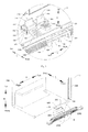
Fig. 1 is a partially schematic view of a side-by-side refrigerator according to an embodiment of the present invention; -
Fig. 2 is a partially exploded view of a side-by-side refrigerator according to an embodiment of the present invention; -
Fig. 3 is an enlarged view of region D inFig. 2 ; -
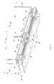
Fig. 4 a partially exploded rear view of a side-by-side refrigerator according to an embodiment of the present invention; -
Fig. 5 is an enlarged view of region E inFig. 4 ; -
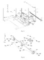
Fig. 6 is a partially exploded view of a side-by-side refrigerator according to an embodiment of the present invention; -
Fig. 7 is a partially exploded view of a side-by-side refrigerator according to an embodiment of the present invention; -
Fig. 8 is a partially sectional view of a side-by-side refrigerator according to an embodiment of the present invention; -
Fig. 9 is an exploded view of a bracket of a side-by-side refrigerator according to an embodiment of the present invention; -
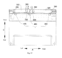
Fig. 10 is a partially schematic view of a side-by-side refrigerator according to another embodiment of the present invention; -
Fig. 11 is a partially schematic view of a side-by-side refrigerator according to another embodiment of the present invention; -
Fig. 12 is a partially schematic view of a side-by-side refrigerator according to another embodiment of the present invention; -
Fig. 13 is a partially schematic view of a side-by-side refrigerator according to another embodiment of the present invention; -
Fig. 14 is a partially schematic view of a side-by-side refrigerator according to another embodiment of the present invention; -
Fig. 15 is a partially exploded view of a side-by-side refrigerator according to another embodiment of the present invention; -
Fig. 16 is a partially schematic view of a side-by-side refrigerator according to another embodiment of the present invention; -
Fig. 17 is a bottom view of a side-by-side refrigerator according to another embodiment of the present invention; -
Fig. 18 is a front view of a side-by-side refrigerator according to another embodiment of the present invention; -
Fig. 19 is a sectional view of the side-by-side refrigerator along a direction of F-F inFig. 18 therein; -
Fig. 20 is a sectional view of the side-by-side refrigerator along a direction of G-G inFig. 18 ; -
Fig. 21 is a sectional view of the side-by-side refrigerator along a direction of H-H inFig. 18 ; -
Fig. 22 is a sectional view of the side-by-side refrigerator along a direction of I-I inFig. 18 ; -
Fig. 23 is a schematic view of a decoration cover of a side-by-side refrigerator according to another embodiment of the present invention. - Reference will be made in detail to embodiments of the present invention. Embodiments of the present invention will be shown in drawings, in which the same or similar elements and the elements having same or similar functions are denoted by like reference numerals throughout the descriptions. The embodiments described herein according to drawings are explanatory and illustrative, not construed to limit the present invention.
- In the specification, unless specified or limited otherwise, relative terms such as "central", "longitudinal", "lateral", "up", "down", "front", "rear", "right", "left", "vertical", "horizontal", "top", "bottom", "inner", "outer", as well as derivative thereof (e.g., "horizontally", "downwardly", "upwardly", etc.) should be construed to refer to the orientation as then described or as shown in the drawings under discussion. These relative terms are for convenience of description and do not require that the present invention be constructed or operated in a particular orientation. In addition, terms such as "first" and "second" are used herein for purposes of description and are not intended to indicate or imply relative importance or significance. Thus, features limited by "first" and "second" are intended to indicate or imply including one or more than one these features. In the description of the present invention, "a plurality of" relates to two or more than two.
- In the description of the present invention, unless specified or limited otherwise, it should be noted that, terms "mounted," "connected" and "coupled" may be understood broadly, such as permanent connection or detachable connection, electronic connection or mechanical connection, direct connection or indirect connection via intermediary, inner communication or interreaction between two elements. These having ordinary skills in the art should understand the specific meanings in the present invention according to specific situations.
- A side-by-
side refrigerator 1 according to embodiments of the present invention will be described in the following with reference toFigs. 1-8 andFigs. 10-22 . As shown inFigs. 1-8 andFigs. 10-22 , the side-by-side refrigerator 1 according to embodiments of the present invention includes arefrigerator body 100, aleft door body 200, aright door body 300, aleft door member 500, aright door member 600, aleft pedal member 700 and aright pedal member 800. - The
left door body 200 and theright door body 300 are rotatably disposed on therefrigerator body 100. Theleft door member 500 is disposed on therefrigerator body 100 and is movable between a left opening position in which theleft door body 200 is opened and a left closing position in which theleft door body 200 is allowed to be closed. Theright door member 600 is disposed on therefrigerator body 100 and is movable between a right opening position in which theright door body 300 is opened and a right closing position in which theright door body 300 is allowed to be closed. - The
left pedal member 700 is connected with theright door member 600 and corresponding to theleft door body 200 in an up and down direction, and theleft pedal member 700 is movable between a left stepping position and a left lifting position. When theleft pedal member 700 moves from the left lifting position to the left stepping position, theright door member 600 is driven to move from the right closing position to the right opening position. Theright pedal member 800 is connected with theleft door member 500 and corresponding to theright door body 300 in the up and down direction, and theright pedal member 800 is movable between a right stepping position and a right lifting position. When theright pedal member 800 moves from the right lifting position to the right stepping position, theleft door member 500 is driven to move from the left closing position to the left opening position. - The left and right direction is illustrated by the arrows A in
Figs. 1-7 ,9-18 and23 . The up and down direction is illustrated by the arrows B inFigs. 1-16 and18-23 . The front and rear direction is illustrated by the arrows C inFigs. 1-17 and19-23 . - Processes of opening the
left door body 200 and theright door body 300 of the side-by-side refrigerator 1 according to embodiments of the present invention will be described in the following with reference toFigs. 1-8 and10-22 . - When a user needs to open the left door body 200 (for example, the user needs to put stuff into a left compartment of the side-by-
side refrigerator 1 or take stuff out of the left compartment of the side-by-side refrigerator 1), the user may step theright pedal member 800 with his foot to move the right pedal member from the right lifting position to the right stepping position, such that theright pedal member 800 may drive theleft door member 500 to move from the left closing position to the left opening position so as to open theleft door 200. In other words, when theright pedal member 800 is in the right lifting position, theleft door member 500 is in the left closing position and theleft door 200 is closed; when theright pedal member 800 is in the right stepping position, theleft door member 500 is in the left opening position and theleft door 200 is open. - When the user needs to open the right door body 300 (for example, the user needs to put stuff into a right compartment of the side-by-
side refrigerator 1 or take stuff out of the right compartment of the side-by-side refrigerator 1), the user may step theleft pedal member 700 with his foot to move the left pedal member from the left lifting position to the left stepping position, such that theleft pedal member 700 may drive theright door member 600 to move from the right closing position to the right opening position so as to open theright door 300. In other words, when theleft pedal member 700 is in the left lifting position, theright door member 600 is in the right closing position and theright door 300 is closed; when theleft pedal member 700 is in the left stepping position, theright door member 600 is in the right opening position and theright door 300 is open. - With the side-by-
side refrigerator 1 according to embodiments of the present invention, by forming a linkage between thelight pedal member 800 and theleft door member 500 and the a linkage between theleft pedal member 700 and theright door member 600, theleft door body 200 may be opened by stepping theright pedal member 800 and theright door body 300 may be opened by stepping theleft pedal member 700, so that in the processes of opening theleft door body 200 and theright door body 300, theleft door body 200 and theright door body 300 will not interfere with feet or legs of the user, and thus it is easier and more convenient for the user to open theleft door body 200 and theright door body 300. Moreover, since the user opens theleft door body 200 by stepping theright pedal member 800 and opens theright door body 300 by stepping theleft pedal member 700, hands of the user can be freed, on the other hand, it is much easier for the user to open theleft door body 200 and theright door body 300. In particular, when the user holds heavy things with his hands, it is easier and more convenient for the user to open theleft door body 200 and theright door body 300. Thus, the door of the side-by-side refrigerator 1 according to embodiments of the present invention is easy and convenient to be opened. - In some embodiments, the
right pedal member 800 is corresponding to theright door body 300 in the up and down direction, i.e., theright pedal member 800 may be located below theright door body 300. In other words, theright pedal member 800 may be located outside of a horizontal projection of theleft door body 200 and may be located within a horizontal projection of theright door body 300. Specifically, theright pedal member 800 may be located at a right side of the horizontal projection of theleft door body 200. Thus, when the user opens theleft door body 200 by stepping theright pedal member 800, theleft door body 200 will not interfere with the user's feet, i.e., theleft door body 200 will not hit the user's feet in the processing of opening theleft door body 200. - Similarly, the
left pedal member 700 is corresponding to theleft door body 200 in the up and down direction, i.e., theleft pedal member 700 may be located below theleft door body 200. In other words, theleft pedal member 700 may be located outside of the horizontal projection of theright door body 300 and may be located within the horizontal projection of theleft door body 200. Specifically, theleft pedal member 700 may be located at a left side of the horizontal projection of theright door body 300. Thus, when the user opens theright door body 300 by stepping theleft pedal member 700, theright door body 300 will not interfere with the user's feet, i.e., theright door body 300 will not hit the user's feet in the processing of opening theright door body 300. - When the
left door body 200 is closed, theleft door body 200 drives theleft door member 500 to move from the left opening position to the left closing position, and thus theleft door member 500 can drive theright pedal member 800 to move from the right stepping position to the right lifting position. When theright door body 300 is closed, theright door body 300 drives theright door member 600 to move from the right opening position to the right closing position, and thus theright door member 600 can drive theleft pedal member 700 to move from the left stepping position to the left lifting position. - Specifically, the
left door body 200 may be disposed on therefrigerator body 100 via a left hinge, and theright door body 300 may be disposed on therefrigerator body 100 via a right hinge. - As shown in
Figs. 1-23 , in some embodiments of the present invention, the side-by-side refrigerator 1 further includes abracket 400, in which theleft door member 500, theright door member 600, theleft pedal member 700 and theright pedal member 800 are disposed on thebracket 400 respectively. By disposing thebracket 400 on therefrigerator body 100, it is easy and convenient to dispose theleft door member 500, theright door member 600, theleft pedal member 700 and theright pedal member 800 on therefrigerator body 100. - In an embodiment of the present invention, the
bracket 400 may be disposed on afront surface 110 of therefrigerator body 100 and may be located below theleft door body 200 and theright door body 300. In other words, thebracket 400 may be disposed on thefront surface 110 of a lower portion of therefrigerator body 100. - As shown in
Figs. 1-8 , in an embodiment of the present invention, theleft door member 500 and theleft pedal member 700 are adjacent to aright edge 240 of theleft door body 200, and theright door member 600 and theright pedal member 800 are adjacent to aleft edge 340 of theright door body 300. Thus, theleft door member 500 is away from the left hinge and theright door member 600 is away from the right hinge, such that theleft door member 500 and theleft pedal member 700 can be arranged compactly, theright door member 600 and theright pedal member 800 can be arranged compactly and it is easy for the user to open theleft door body 200 and theright door body 300 with less effort. - Specifically, since the
left door member 500 is adjacent to theright edge 240 of theleft door body 200, when the user steps theright pedal member 800 to open theleft door body 200, an action point of a force acted on theleft door body 200 by theleft door member 500 is away from the left hinge, such that the force acted on theleft door body 200 by theleft door member 500 has the maximum force arm, and thus the user can open theleft door body 200 with a little effort. - Similarly, since the
right door member 600 is adjacent to theleft edge 340 of theright door body 300, when the user steps theleft pedal member 700 to open theright door body 300, an action point of a force acted on theright door body 300 by theright door member 600 is away from the right hinge, such that the force acted on theright door body 300 by theright door member 600 has the maximum force arm, and thus the user can open theright door body 300 with a little effort. - As shown in
Figs. 1-8 , in some embodiments of the present invention, the side-by-side refrigerator 1 may further includes afirst shaft 900 and asecond shaft 1000. Thefirst shaft 900 and thesecond shaft 1000 may be pivotally disposed on thebracket 400 and be spaced from each other in the front and rear direction and in the up and down direction, thesecond shaft 1000 defines a left end connected with theleft door member 500 and a right end connected with theright pedal member 800, and thefirst shaft 900 defines a right end connected with theright door member 600 and a left end connected with theleft pedal member 700. - In other words, the
left door member 500 is disposed on thebracket 400 and rotated between the left opening position and the left closing position, and theright door member 600 is disposed on thebracket 400 and rotated between the right opening position and the right closing position, and theleft pedal member 700 is rotated between the left stepping position and the left lifting position and theright pedal member 800 is rotated between the right stepping position and the right lifting position. With thefirst shaft 900 and thesecond shaft 1000 being spaced from each other both in the up and down direction and in the front and rear direction, thefirst shaft 900 and thesecond shaft 1000 are prevented from interfering with theleft pedal member 700, theleft door member 500, theright pedal member 800 and theright door member 600. By disposing thefirst shaft 900 and thesecond shaft 1000, it is easier to dispose theleft pedal member 700, theleft door member 500, theright pedal member 800 and theright door member 600 on thebracket 400. In an embodiment of the present invention, thefirst shaft 900 may be parallel with thesecond shaft 1000, andfirst shaft 900 and thesecond shaft 1000 are extended in the left and right direction. - A fixed end of the left door member 500 (a lower end of the left door member 500) may be connected with a left end of the
second shaft 1000, a free end of the left door member 500 (an upper end of the left door member 500) may be extended upwards and located between a lower portion of theleft door body 200 and therefrigerator body 100. A fixed end of the right door member 600 (a lower end of the right door member 600) may be connected with a right end of thefirst shaft 900, a free end of the right door member 600 (an upper end of the right door member 600) may be extended upwards and located between a lower portion of theright door body 300 and therefrigerator body 100. In an embodiment of the present invention, the free end of theleft door member 500 may contact with the lower portion of theleft door body 200 and the free end of theright door member 600 may contact with the lower portion of theright door body 300. - Specifically, as shown in
Fig. 7 , thefirst shaft 900 is located above thesecond shaft 1000, the left compartment is a freezing chamber and the right compartment is a refrigerating chamber. A left power-assisted opening mechanism consists of theleft door member 500, thesecond shaft 1000 and the right pedal member, and a right power-assisted opening mechanism consists of theright door member 600, thefirst shaft 900 and theleft pedal member 700. - In an embodiment of the present invention, the
left door member 500, thesecond shaft 1000, and theright pedal member 800 are formed integrally, and theright door member 600, thefirst shaft 900 and theleft pedal member 700 are formed integrally. Thus, structural strengths of the left power-assisted opening mechanism and the right power-assisted opening mechanism can be improved, producing processes of the left power-assisted opening mechanism and the right power-assisted opening mechanism can be simplified and producing costs of the left power-assisted opening mechanism and the right power-assisted opening mechanism can be reduced. Specifically, theleft door member 500, thesecond shaft 1000, and theright pedal member 800 are formed by integral injection molding, and theright door member 600, thefirst shaft 900 and theleft pedal member 700 are formed by integral injection molding. - As shown in
Figs. 1-7 , in an embodiment of the present invention, theleft pedal member 700 and theright pedal member 800 may be configured as pedals (i.e., the left pedal member is a pedal and the right pedal member also may be a pedal), theleft door member 500 and theright door member 600 may be configured as plates (i.e., theleft door member 500 is a plate and theright door member 600 is a plate), theright pedal member 800 is aligned with theright door member 600 and theleft pedal member 700 is aligned with theleft door member 500. - By configuring the
left pedal member 700 and theright pedal member 800 as pedals, contact areas between the user's feet and theleft pedal member 700 and between the user's feet and theright pedal member 800 can be increased, and thus it is easier for the user to step the left pedal member and theright pedal member 800. By configuring theleft door member 500 and theright door member 600 as plates, contact areas between theleft door member 500 and theleft door body 200 and between theright door member 600 and theright door body 300 can be increased, and thus it is much easier for the user to open theleft door body 200 and theright door body 300. By aligning theright pedal member 800 with theright door member 600 and theleft pedal member 700 with the left door member 500 (i.e., aligning theright pedal member 800 with theright door member 600 in the left and right direction and aligning theleft pedal member 700 with theleft door member 500 in the left and right direction), theleft door member 500 and theleft pedal member 700 are arranged compactly, and theright door member 600 and theright pedal member 800 are arranged compactly. - In an embodiment of the present invention,
antiskid stripes 1100 may be formed in an upper surface of theleft pedal member 700 and may also be formed in an upper surface of theright pedal member 800, such that friction forces between the user's feet and theleft pedal member 700 and between the user's feet and theright pedal member 800 can be improved, thus performing a skid resistance function and further making it easier for the user to operate. - As shown in
Figs. 2-9 , in some embodiments of the present invention, thebracket 400 further includes arear frame 410 and afront frame 420. Therear frame 410 has an L-shaped cross-section and has a firstvertical portion 411 and a firsthorizontal portion 413, and afirst support plate 412 is disposed on the firstvertical portion 411 and defines afirst clamping groove 414 and asecond clamping groove 415. - The
front frame 420 has an inverted L-shaped cross-section and has a secondvertical portion 421 and a secondhorizontal portion 427, asecond support plate 422 is disposed on the secondvertical portion 421 and is spaced from thefirst support plate 412 in the right and left direction, and thesecond support plate 422 defines athird clamping groove 423 and afourth clamping groove 424. Thefirst shaft 900 is pivotally fitted in thefirst clamping groove 414 and thethird clamping groove 423, thesecond shaft 1000 is pivotally fitted in thesecond clamping groove 415 and thefourth clamping groove 424. A leftdoor member window 428 and a rightdoor member window 429 are formed in the secondhorizontal portion 427, a leftpedal member window 425 and a rightpedal member window 426 are formed in the secondvertical portion 421, afree end 510 of theleft door member 500 is extended upwards and passed through the leftdoor member window 428 and afree end 610 of theright door member 600 is extended upwards and passed through the rightdoor member window 429, and afree end 710 of the left pedal member 710 (a front end of the left pedal member 700) is extended forwards and passed through the leftpedal member window 425 and afree end 810 of the right pedal member 800 (a front end of the right pedal member 800) is extended forwards and passed through the rightpedal member window 426. - By disposing the
rear frame 410 and thefront frame 420, a space configured to receive a part of theleft door member 500, a part of theright door member 600, a part of theleft pedal member 700, a part of theright pedal member 800, thefirst shaft 900 and thesecond shaft 1000 is defined, such that the side-by-side refrigerator 1 has a simple and artistic appearance and theleft door member 500, theright door member 600, theleft pedal member 700, theright pedal member 800, thefirst shaft 900 and thesecond shaft 1000 can be protected. Moreover, by defining thefirst clamping groove 414 and thesecond clamping groove 415 in thefirst support plate 412 of therear frame 410 and defining thethird clamping groove 423 and thefourth clamping groove 424 in thesecond support plate 422 of thefront frame 420, it is much easier to dispose thefirst shaft 900 and thesecond shaft 1000 on the bracket pivotally. - Specifically, a rear end of the second
horizontal portion 427 of thefront frame 420 contacts with an upper end of the firstvertical portion 411 of therear frame 410, and a lower end of the secondvertical portion 421 of thefront frame 420 contacts with a front end of thehorizontal portion 413 of therear frame 410, and thus a chamber with a general rectangle shape is defined by therear frame 410 with the L-shaped cross-section and thefront frame 420 with the inverted L-shaped cross-section. Thefirst support plate 412 is disposed on a front surface of the firstvertical portion 411 of the rear frame 410 (a surface of the firstvertical portion 411 close to the user) and is extended forwards. Thesecond support plate 422 is disposed on a rear surface of the secondvertical portion 421 of the front frame 420 (a surface of the vertical portion away from the user) and is extended backwards. Thefirst clamping groove 414 and thesecond clamping groove 415 may be formed in thefirst support plate 412 and spaced from each other in the up and down direction, and thethird clamping groove 423 and thefourth clamping groove 424 may be formed in thesecond support plate 422 and spaced from each other in the up and down direction. - In an embodiment of the present invention, as shown in
Fig. 9 , both thefirst support plate 412 and thesecond support plate 422 may be oriented in the front and rear direction, rear ends of thefirst clamping groove 414 and thesecond clamping groove 415 may be configured as semicircles, and front ends of thethird clamping groove 423 and thefourth clamping groove 424 may be configured as semicircles, such that thefirst shalt 900 can be fitted in thefirst clamping groove 414 and thethird clamping groove 423 stably and thesecond shaft 1000 may be fitted in thesecond clamping groove 415 and thefourth clamping groove 424 stably. - There may be a plurality of
first support plates 412, and the plurality offirst support plates 412 are disposed on the firstvertical portion 411 of therear frame 410 and spaced from each other in the left and right direction. There may be a plurality ofsecond support plates 422, and the plurality ofsecond support plates 422 are disposed on the secondvertical portion 421 of thefront frame 420 and spaced from each other in the left and right direction. Eachfirst support plate 412 is spaced from eachsecond support 422 in the left and right direction. By disposing the plurality offirst support plates 412 andsecond support plates 422, thefirst shaft 900 and thesecond shaft 1000 can be supported stably. - In an embodiment of the present invention, the
first support plate 412 and therear frame 410 are formed integrally, and thesecond support plate 422 and thefront frame 420 are formed integrally. Specifically, thefirst support plate 412 and therear frame 410 are integrally formed by injection molding, and thesecond support plate 422 and thefront frame 420 are integrally formed by injection molding, and thus the structural strength is improved, the producing process is simplified and the producing cost is reduced. - As shown in
Fig.5 , in an embodiment of the present invention, lower ends of theleft pedal window 425 and theright pedal window 426 are open, such that it is easy to dispose theleft pedal member 700 and theright pedal member 800, i.e., it is easy to dispose the left power-assisted opening mechanism and the right power-assisted opening mechanism. - As shown in
Figs. 3 and5 , in an embodiment of the present invention, therear frame 410 further includes afirst side plate 430, thefront frame 420 further includes asecond side plate 440, one of thefirst side plate 430 and thesecond side plate 440 defines a slidinggroove 450 and the other thereof has a slidingrail 460 which is fitted in the slidinggroove 450 and movable in the front and rear direction within the slidinggroove 450. By disposing thefirst side plate 430, thesecond side plate 440, the slidinggroove 450 and the slidingrail 460, it is easy and convenient to assembly therear frame 410 and thefront frame 420 detachably. - Specifically, there may be two
first side plates 430, and one is disposed at a left side of therear frame 410 and the other one is disposed at a right side of therear frame 410; there may be twosecond side plates 440, one is disposed at a left side of thefront frame 420 and the other one is disposed at a right side of thefront frame 420. - In an embodiment of the present invention, the
first side plate 430 and therear frame 410 are formed integrally, and thesecond side plate 440 and thefront frame 420 are formed integrally. Specifically, thefirst side plate 430 and therear frame 410 are integrally formed by injection molding, and thesecond side plate 440 and thefront frame 420 are integrally formed by injection molding, and thus the structural strength is improved, the producing process is simplified and the producing cost is reduced. - As shown in
Figs. 1-7 , in an embodiment of the present invention, the side-by-side refrigerator 1 further includes abottom beam cover 1200 disposed on abottom beam 140 of therefrigerator body 100 and formed with thefront frame 420 integrally. Specifically, thebottom beam cover 1200 is formed with thefront frame 420 by injection molding integrally, and thus the structural strength is improved, the producing process is simplified and the producing cost is reduced. - As shown in
Fig. 8 , in an embodiment of the present invention, the side-by-side refrigerator 1 includes a first elastic member (not shown) and a secondelastic member 1300. The first elastic member is disposed between theleft pedal member 700 and thebracket 400 and is configured to push theleft pedal member 700 from the left stepping position to the left lifting position. The secondelastic member 1300 is disposed between theright pedal member 800 and thebracket 400 and is configured to push theright pedal member 800 to the right lifting position from the right stepping position. - In other words, when the user steps the
left pedal member 700, i.e., when theleft pedal member 700 is in the left stepping position, the first elastic member is compressed; when the user's feet are removed from theleft pedal member 700, the first elastic member moves theleft pedal member 700 from the left stepping position to the left lifting position. Likewise, when the user steps theright pedal member 800, i.e., when theright pedal member 800 is in the right stepping position, the secondelastic member 1300 is compressed; when the user's feet are removed from theright pedal member 800, the secondelastic member 1300 moves theright pedal member 800 from the right stepping position to the right lifting position. - By disposing the first elastic member and the second
elastic member 1300, theleft pedal member 700 and theright door member 600 can be reset when the user's feet are removed from theleft pedal member 700, and theright pedal member 800 and theleft door member 500 can be reset when the user's feet are removed from theright pedal member 800. - Specifically, a first end of the first elastic member is connected with a lower surface of the
left pedal member 700 and a second end of the first elastic member is connected with an upper surface of the firsthorizontal portion 413 of therear frame 410. The first end of the second elastic member 1300 (an upper end of the secondelastic member 1300 inFig. 8 ) is connected with a lower surface of theright pedal member 800 and a second end of the second elastic member 1300 (a lower end of the secondelastic member 1300 inFig. 8 ) is connected with the upper surface of the firsthorizontal portion 413 of therear frame 410. - In an embodiment of the present invention, a left boss is disposed on a lower surface of the
left door body 200, and thefree end 510 of theleft door member 500 is located between the left boss and thefront surface 110 of therefrigerator body 100; a right boss is disposed on a lower surface of theright door body 300, and thefree end 610 of theright door member 600 is located between the right boss and thefront surface 110 of therefrigerator body 100. - Thus, when the user opens the
left door body 200 via theleft door member 500 and opens theright door body 300 via theright door member 600, theleft door member 500 applies a force to the left boss and theright door member 600 applies a force to the right boss. In other words, by disposing the left boss on the lower surface of theleft door body 200, theleft door member 500 is prevented from applying a force to the left door body directly; by disposing the right boss on the lower surface of theright door body 300, theright door member 600 is prevented from applying a force to theright door body 300 directly. Therefore, theleft door body 200 and theright door body 300 will not be damaged after having been opened for many times, thus increasing a working life of theleft door body 200 and theright door body 300, i.e., increasing a working life of the side-by-side refrigerator 1. - In an embodiment of the present invention, the left boss is disposed on the lower surface of the
left door body 200 detachably, and the right boss is disposed on the lower surface of theright door body 300 detachably. Thus, if the left boss and the right boss are damaged, they can be replaced. In addition, a cost of replacing the left boss and the right boss is much less than that of replaying theleft door body 200 and theright door body 300. - As shown in
Figs. 10-22 , in other embodiments of the present invention, the side-by-side refrigerator 1 may further includes afirst shaft 900 and asecond shaft 1000. Thefirst shaft 900 and thesecond shaft 1000 may be pivotally disposed on thebracket 400 and be spaced from each other in the up and down direction, thesecond shaft 1000 is connected with theleft door member 500 and defines a right end connected with the right pedal member 80, and thefirst shaft 900 is connected with theright door member 600 and defines a left end connected with theleft pedal member 700. - In other words, the
left door member 500 is disposed on thebracket 400 and rotated between the left opening position and the left closing position, and theright door member 600 is disposed on thebracket 400 and rotated between the right opening position and the right closing position, and theleft pedal member 700 is rotated between the left stepping position and the left lifting position and theright pedal member 800 is rotated between the right stepping position and the right lifting position. Thefirst shaft 900 and thesecond shaft 1000 are spaced from each other both in the up and down direction, and thus thefirst shaft 900 and thesecond shaft 1000 are prevented from interfering with theleft pedal member 700 and theright pedal member 800. - By disposing the
first shaft 900 and thesecond shaft 1000, it is easier to dispose theleft pedal member 700, theleft door member 500, theright pedal member 800 and theright door member 600 on thebracket 400. In an embodiment of the present invention, thefirst shaft 900 may be parallel with thesecond shaft 1000, andfirst shaft 900 and thesecond shaft 1000 are extended in the left and right direction. - A fixed end of the left door member 500 (a lower end of the left door member 500) may be connected with a left end of the
second shaft 1000, a free end of the left door member 500 (an upper end of the left door member 500) may be extended upwards and located between a lower portion of theleft door body 200 and therefrigerator body 100. A fixed end of the right door member 600 (a lower end of the right door member 600) may be connected with a right end of thefirst shaft 900, a free end of the right door member 600 (an upper end of the right door member 600) may be extended upwards and located between a lower portion of theright door body 300 and therefrigerator body 100. In an embodiment of the present invention, the free end of theleft door member 500 may contact with the lower portion of theleft door body 200 and the free end of theright door member 600 may contact with the lower portion of theright door body 300. - Specifically, as shown in
Figs. 10-12 and16 , thefirst shaft 900 is located below thesecond shaft 1000, the left compartment is a freezing chamber and the right compartment is a refrigerating chamber. A left power-assisted opening mechanism consists of theleft door member 500, thesecond shaft 1000 and theright pedal member 800, and a right power-assisted opening mechanism consists of theright door member 600, thefirst shaft 900 and theleft pedal member 700. - In an embodiment of the present invention, the
left door member 500, thesecond shaft 1000, and theright pedal member 800 are formed integrally, and theright door member 600, thefirst shaft 900 and theleft pedal member 700 are formed integrally. Thus, structural strengths of the left power-assisted opening mechanism and the right power-assisted opening mechanism can be improved, producing processes of the left power-assisted opening mechanism and the right power-assisted opening mechanism can be simplified and producing costs of the left power-assisted opening mechanism and the right power-assisted opening mechanism can be reduced. - As shown in
Figs. 10-18 , in another embodiment of the present invention, theleft door member 500 is adjacent to aleft edge 230 of theleft door body 200, and theright door member 600 is adjacent to aright edge 330 of theright door body 300, such that theleft door member 500 is adjacent to the left hinge and theright door member 600 is adjacent to the right hinge. Thus, theleft door body 200 can be opened with a larger angle by theleft door member 500, and theright door body 300 can be opened with a larger angle by theright door member 600. In other words, theleft door body 200 and theright door body 300 have larger power-assisted travels. - Specifically, by disposing the
left door member 500 in a position adjacent to theleft edge 230 of theleft door body 200, when theright pedal member 800 is stepped to open theleft door body 200, in a case that theleft door member 500 is rotated a certain angle, theleft door body 200 can have the maximum power-assisted travel, i.e., theleft door body 200 is opened with the maximum angle. Likewise, by disposing theright door member 600 in a position adjacent to theright edge 330 of theright door body 300, when theleft pedal member 700 is stepped to open theright door body 300, in a case that theright door member 600 is rotated a certain angle, theright door body 300 can have the maximum power-assisted travel, i.e., theright door body 300 is opened with the maximum angle. - Specifically, as shown in
Figs. 10-18 , theleft pedal member 700 is adjacent to theright edge 240 of theleft door body 200, and theright pedal member 800 is adjacent to theleft edge 340 of theright door body 300. By disposing theleft pedal member 700 in a position adjacent to theright edge 240 of theleft door body 200 and disposing theright pedal member 800 in a position adjacent to theleft edge 340 of theright door body 300, theleft pedal member 700 and theright pedal member 800 can be arranged compactly. - As shown in
Figs. 10-18 , in some embodiments of the present invention, theleft door member 500 includes a firstleft door arm 520 and a secondleft door arm 530. The firstleft door arm 520 is connected with the left end of thesecond shaft 1000 and is adjacent to theleft edge 230 of theleft door body 200 and the secondleft door arm 530 is connected with thesecond shaft 1000 and is located between the firstleft door arm 520 and theright pedal member 800. Theright door member 600 includes a firstright door arm 620 and a secondright door arm 630. The firstright door arm 620 is connected with the right end of thefirst shaft 900 and is adjacent to theright edge 330 of theright door body 300 and the secondright door arm 630 is connected with thefirst shaft 900 and is located between the firstright door arm 620 and theleft pedal member 700. - In other words, each of the first
left door arm 520 and the secondleft door arm 530 may be disposed on thebracket 400 and rotated between the left opening position and the left closing position, and each of the firstright door arm 620 and the secondright door arm 630 may be disposed on thebracket 400 and rotated between the right opening position and the right closing position. - Processes of opening the
left door 200 and theright door 300 of the side-by-side refrigerator 1 according to embodiments of the present invention will be described in the following with reference toFigs. 10-22 . - When the user needs to open the left door body 200 (for example, the user needs to put stuff into a left compartment of the side-by-
side refrigerator 1 or get stuff out of the left compartment of the side-by-side refrigerator 1), the user may step theright pedal member 800 with his foot to move theright pedal member 800 from the right lifting position to the right stepping position, such that theright pedal member 800 may drive the firstleft door arm 520 and the secondleft door arm 530 to move from the left closing position to the left opening position so as to open theleft door 200. In other words, when theright pedal member 800 is in the right lifting position, the firstleft door arm 520 and the secondleft door arm 530 are in the left closing position and theleft door 200 is closed; when theright pedal member 800 is in the right stepping position, the firstleft door arm 520 and the secondleft door arm 530 are in the left opening position and theleft door 200 is open. - When the user needs to open the right door body 300 (for example, the user needs to put stuff into a right compartment of the side-by-
side refrigerator 1 or get stuff out of the right compartment of the side-by-side refrigerator 1), the user may step theleft pedal member 700 with his foot to move the left pedal member from the left lifting position to the left stepping position, such that theleft pedal member 700 may drive the firstright door arm 620 and the secondright door arm 630 to move from the right closing position to the right opening position so as to open theright door 300. In other words, when theleft pedal member 700 is in the left lifting position, the firstright door arm 620 and the secondright door arm 630 are in the right closing position and theright door 300 is closed; when theleft pedal member 700 is in the left stepping position, the firstright door arm 620 and the secondright door arm 630 are in the right opening position and theright door 300 is open. - Since the first
left door arm 520 is adjacent to theleft edge 230 of theleft door body 200 and the firstright door arm 620 is adjacent to theright edge 330 of the right door body 300 (i.e., the firstleft door arm 520 is adjacent to the left hinge and the firstright door arm 620 is adjacent to the right hinge), theleft door body 200 can be opened with a larger angle by the firstleft door arm 520 and theright door 300 can be opened with a larger angle by the firstright door arm 620. In other words, theleft door body 200 and theright door body 300 have larger power-assisted travels. Since the secondleft door arm 530 is away from to theleft edge 230 of theleft door body 200 and the secondright door arm 630 is away from to theright edge 330 of the right door body 300 (i.e., the secondleft door arm 530 is away from to the left hinge and the secondright door arm 630 is away to the right hinge), an action point of a force acted on theleft door body 200 by the secondleft door arm 530 is away from the left hinge, and an action point of a force acted on theright door body 300 by the secondright door arm 630 is away from the right hinge, and thus the user can open theleft door 200 and theright door 300 with a little effort. - Therefore, by disposing the first
left door arm 520 adjacent to theleft edge 230 of theleft door body 200 and disposing the secondleft door arm 530 away from to theleft edge 230 of theleft door body 200, not only the user can open theleft door 200 with a little effort, but also theleft door body 200 can have a larger power-assisted travel. By disposing the firstright door arm 620 adjacent to theright edge 330 of theright door body 300 and disposing the secondright door arm 630 away from to theright edge 330 of theright door body 300, not only the user can open theright door 300 with a little effort, but also theright door body 300 can have a larger power-assisted travel. - In some embodiments of the present invention, in the left closing position, the second
left door arm 530 contacts with theleft door body 200 and the firstleft door arm 520 is spaced from theleft door body 200 with a certain distance (such as 3mm to 20mm, preferably 10mm); in the right closing position, the secondright door arm 630 contacts with theright door body 300 and the firstright door arm 620 is spaced from theright door body 300 with a certain distance (such as 3mm to 20mm, preferably 10mm). - The process of opening the
left door body 200 of the side-by-side of therefrigerator 1 according to embodiments of the present invention will be described in the following with reference toFigs. 10-22 . - When the user steps the
right pedal member 800 to move theright pedal member 800 from the right lifting position to the right stepping position, the firstleft door arm 520 and the secondleft door arm 530 are rotated forwards (i.e., swung forwards). Since the secondleft door arm 530 contacts with theleft door body 200, theleft door body 200 is opened with a certain angle (such as 3 degrees to 5 degrees) by the secondleft door arm 530, and thus theleft door 200 is beyond a magnetism scope of a door gasket. As theleft door body 200 is opened, the secondleft door arm 530 separates from theleft door body 200 and the first left door body contacts with theleft door body 200 so as to continuously open the left door body 200 (at the moment, theleft door 200 has been beyond the magnetism scope of the door gasket and has a certain initial velocity, and thus theleft door body 200 has a small opening resistance), until the firstleft door arm 520 separates from theleft door body 200. Finally, theleft door body 200 can be opened with an angle of 5 degrees to 20 degrees and even be opened with an angle larger than 90 degrees by means of inertance thereof. The process of opening theright door body 300 is the same with that of opening theleft door body 200 and is omitted herein. - In an embodiment of the present invention, the
left pedal member 700 and the secondleft door arm 530 may be adjacent to theright edge 240 of theleft door body 200, and theright pedal member 800 and the secondright door arm 630 may be adjacent to leftedge 340 of theright door body 300. By disposing the secondleft door arm 530 in a position adjacent to theright edge 240 of theleft door body 200, the force acted on theleft door body 200 by the secondleft door arm 530 has the longest force arm, and thus the user can open theleft door body 200 with a little effort. Likewise, by disposing the secondright door arm 630 in a position adjacent to theleft edge 340 of theright door body 300, the force acted on theright door body 300 by the secondright door arm 630 has the longest force arm, and thus the user can open theright door body 300 with a little effort. - Moreover, by disposing the
left pedal member 700 in a position adjacent to theright edge 240 of theleft door body 200 and disposing theright pedal member 800 in a position adjacent to theleft edge 340 of theright door body 300, theleft pedal member 700, the secondleft door arm 530, theright pedal member 800 and the secondright door arm 630 can be arranged compactly. - As shown in
Figs. 10-13 andFigs. 15-16 , in some embodiments of the present invention, the firstleft door arm 520, the secondleft door arm 530, the firstright door arm 620 and the secondright door arm 630 may be configured as rods. Theleft pedal member 700 includes aleft support rod 720 connected with the left end of thefirst shaft 900 and aleft pedal 730 disposed on theleft support rod 720, theright pedal member 800 includes aright support rod 820 connected with the right end of thesecond shaft 1000 and aright pedal 830 disposed on theright support rod 820. The firstleft door arm 520, thesecond shaft 1000 and theright support rod 820 are formed integrally, and the firstright door arm 620, thefirst shaft 900 and theleft support rod 720 are formed integrally. - By disposing the
right pedal 830 on theright support rod 820 and disposing theleft pedal 730 on theleft support rod 720, theleft pedal member 700 and theright pedal member 800 have artistic appearances, and the contact areas between the user's feet and theright pedal member 800 and theleft pedal member 700 are increased, such that it is easier for the user to step theright pedal member 800 and theleft pedal member 700. In some embodiments, antiskid stripes may be formed in an upper surface of theleft pedal 730 and may also be formed in an upper surface of theright pedal 830, such that friction forces between the user's feet and theleft pedal 730 and between the user's feet and theright pedal 830 can be improved, thus performing a skid resistance function and further making it easier for the user to operate. - Specifically, the first
left door arm 520, thesecond shaft 1000 and theright support rod 820 are made of a steel bar with a diameter of 8mm by bending, and a first end of the steel bar is bent forwards with an angle of 90 degrees so as to from theright support rod 820, and a second end of the steel bar is bent upwards with an angle of 90 degrees so as to form the firstleft door arm 520. The firstright door arm 620, thefirst shaft 900 and theleft support rod 720 also are made of a steel bar with a diameter of 8mm by bending, and a manufacturing method thereof is the same with that in above descriptions. In addition, the secondleft door arm 530 and the secondright door arm 630 are made of steel, and the secondleft door arm 530 is welded on thesecond shaft 1000 and the secondright door arm 630 is welded on thefirst shaft 900. - In the left closing position, the first
left door arm 520 and the secondleft door arm 530 are oriented in the up and down direction; in the right closing position, the firstright door arm 620 and the secondright door arm 630 are oriented in the up and down direction. In the left lifting position, theleft support rod 720 and theleft pedal 730 are oriented in a front and rear position; in the right lifting position, theright support rod 820 and theright pedal 830 are oriented in the front and rear direction. Thesecond shaft 1000 is orthogonal to each of the firstleft door arm 520, the secondleft door arm 530, theright support rod 820 and theright pedal 830, and thefirst shaft 900 is orthogonal to each of the firstright door arm 620, the secondright door arm 630, theleft support rod 720 and theleft pedal 730. - As shown in
Figs. 10-15 ,17 and19-22 , in some embodiments of the present invention, a firstleft boss 250 and a secondleft boss 260 are disposed on alower surface 220 of theleft door body 200, afree end 521 of the firstleft door arm 520 is located between the firstleft boss 250 and afront surface 110 of therefrigerator body 100, and afree end 531 of the secondleft door arm 530 is located between the secondleft boss 260 and thefront surface 110 of therefrigerator body 100. A firstright boss 350 and a secondright boss 360 are disposed on alower surface 320 of theright door body 300, afree end 621 of the firstright door arm 620 is located between the firstright boss 360 and thefront surface 110 of therefrigerator body 100, and afree end 631 of the secondright door arm 630 is located between the secondright boss 360 and thefront surface 110 of therefrigerator body 100. - Therefore, when the user opens the
left door body 200 with the firstleft door arm 520 and the secondleft door arm 530 and opens theright door body 300 with the firstright door arm 620 and the secondright door arm 630, the firstleft door arm 520 applies a force to the firstleft boss 250 and the secondleft door arm 530 applies a force to the secondleft boss 260, and the firstright door arm 620 applies a force to the firstright boss 350 and the secondright door arm 630 applies a force to the secondright boss 360. In other words, by disposing the firstleft boss 250 and the secondleft boss 260 on thelower surface 220 of theleft door body 200, the firstleft door arm 520 and the secondleft door arm 530 are prevented from applying a force to theleft door body 200 directly; by disposing the firstright boss 350 and the secondleft door boss 360 on thelower surface 320 of theright door body 300, the firstright door arm 620 and the secondleft door arm 630 are prevented from applying a force to theright door body 300 directly. Therefore, theleft door body 200 and theright door body 300 will not be damaged after having been opened for many times, thus increasing a working life of theleft door body 200 and theright door body 300, i.e., increasing a working life of the side-by-side refrigerator 1. - In an embodiment of the present invention, the first
left boss 250 and the secondleft boss 260 are disposed on thelower surface 220 of theleft door body 200 detachably, and the firstright boss 350 and the secondright boss 360 are disposed on thelower surface 320 of theright door body 300 detachably. Thus, if the firstleft boss 250, the secondleft boss 260, the firstright boss 350 and the secondright boss 360 are damaged, they can be replaced. In addition, a cost of replacing the firstleft boss 250, the secondleft boss 260, the firstright boss 350 and the secondright boss 360 is much less than that of replaying theleft door body 200 and theright door body 300. - Specifically, in the left closing position, the second
left door arm 530 contacts with the secondleft boss 260 and the firstleft door arm 520 is spaced from the firstleft boos 250 with a certain distance (such as 3mm-20mm, preferably 10mm); in the right closing position, the secondright door arm 630 contacts with the secondright boss 360 and the firstright door arm 620 is spaced from the firstright boss 350 with a certain distance (such as 3mm-20mm, preferably 10mm). - In an embodiment of the present invention, the
bracket 400 includes afirst support 470, asecond support 480 and athird support 490. Thefirst support 470 is located below theleft door body 200 and is adjacent to theleft edge 230 of theleft door body 200. Thesecond support 480 is located below theleft door body 200 and/or theright door body 300. Thethird support 490 is located below theright door body 300 and is adjacent to theright edge 330 of theright door body 300. The right end of thefirst shaft 900 is supported on thethird support 490, the left end of thesecond shaft 1000 is supported on thefirst support 470, and the left end of thefirst shaft 900 and the right end of thesecond shaft 1000 are supported on thesecond support 480. By disposing thefirst support 470, thesecond support 480 and thethird support 490, thefirst shaft 900 and thesecond shaft 1000 can be disposed on the side-by-side refrigerator 1 stably. - Specifically, each of the
first support 470, thesecond support 480 and thethird support 490 includes a third vertical portion and a third horizontal portion. The third vertical portion is disposed on a front surface of thebottom beam 140 of therefrigerator body 100, and afirst shaft hole 481 and asecond shaft hole 482 penetrated through the third vertical portion in the left and right direction are spaced from each other in the up and down direction. The third horizontal portion is disposed on a lower face of therefrigerator body 100, and a front edge of the third horizontal portion is connected with a lower edge of the third vertical portion. By forming thefirst shaft hole 481 and thesecond shaft hole 482 in each of thefirst support 470, thesecond support 480 and thethird support 490, a product standardization level can be improved and kinds of components and parts can be reduced. - In an embodiment of the present invention, the side-by-
side refrigerator 1 further includes a first reinforcer, a second reinforcer and a third reinforcer. The first reinforcer, the second reinforcer and the third reinforcer may be disposed on a rear surface of thebottom beam 140 of therefrigerator body 100 and spaced from one another. Thefirst support 470 may be disposed on thebottom beam 140 of therefrigerator body 100 and the first reinforcer by a first fastener. Thesecond support 480 may be disposed on thebottom beam 140 of therefrigerator body 100 and the second reinforcer by a second fastener. Thethird support 490 may be disposed on thebottom beam 140 of therefrigerator body 100 and the third reinforcer by a third fastener. By disposing the first reinforcer, the second reinforcer and the third reinforcer, thefirst support 470, thesecond support 480, thethird support 490 can be disposed on thebottom beam 140 of therefrigerator body 100 stably and can bear larger forces. The first fastener, the second fastener and the third fastener may be screws. - As shown in
Figs. 14-15 and23 , the side-by-side refrigerator 1 further includes adecoration cover 1400 disposed on thebottom beam 140 of therefrigerator body 100. Afirst gap 1411 and asecond gap 1422 are formed in a rear edge of anupper surface 1410 of thedecoration cover 1400, and athird gap 1421 and afourth gap 1422 are formed in a lower edge of afront surface 1420 of thedecoration cover 1400. Thefree end 510 of theleft door member 500 is extended upwards and passed through thefirst gap 1411, thefree end 610 of theright door member 600 is extended upwards and passed through thesecond gap 1412, thefree end 710 of theleft pedal member 700 is extended forwards and passed through thethird gap 1421, and thefree end 810 of theright pedal member 800 is extended forwards and passed through thefourth gap 1422. - By disposing the
decoration cover 1400 on thebottom beam 140 of therefrigerator body 100, theleft door member 500, theright door member 600, theleft pedal member 700 and theright pedal member 800 can be covered up, thus providing an artistic appearance with the side-by-side refrigerator 1. - In an embodiment of the present invention, a
first opening 1423 and asecond opening 1424 are formed in thedecoration cover 1400. Thefree end 521 of the firstleft door arm 520 is extended upwards and passed through thefirst gap 1411, thefree end 531 of the secondleft door arm 530 is extended upwards and passé through thefirst opening 1423, thefree end 621 of the firstright door arm 620 is extended upwards and passed through thesecond gap 1412, and the free end 632 of the secondright door arm 630 is extended upwards and passed through thesecond opening 1424. - With the side-by-
side refrigerator 1 according to embodiments of the present invention, it is easy and convenient for the user to open the doors thereof. - Reference throughout this specification to "an embodiment," "some embodiments," "one embodiment", "another example," "an example," "a specific example," or "some examples," means that a particular feature, structure, material, or characteristic described in connection with the embodiment or example is included in at least one embodiment or example of the present invention. Thus, the appearances of the phrases such as "in some embodiments," "in one embodiment", "in an embodiment", "in another example," "in an example," "in a specific example," or "in some examples," in various places throughout this specification are not necessarily referring to the same embodiment or example of the present invention. Furthermore, the particular features, structures, materials, or characteristics may be combined in any suitable manner in one or more embodiments or examples.
- Although explanatory embodiments have been shown and described, it would be appreciated by those skilled in the art that the above embodiments cannot be construed to limit the present invention, and changes, alternatives, and modifications can be made in the embodiments without departing from spirit, principles and scope of the present invention.
Claims (22)
- A side-by-side refrigerator, comprising:a refrigerator body;a left door body and a right door body rotatably disposed on the refrigerator body;a left door member disposed on the refrigerator body and movable between a left opening position in which the left door body is opened and a left closing position in which the left door body is allowed to be closed;a right door member disposed on the refrigerator body and movable between a right opening position in which the right door body is opened and a right closing position in which the right door body is allowed to be closed;a left pedal member connected with the right door member, corresponding to the left door body in an up and down direction and movable between a left stepping position and a left lifting position, wherein when the left pedal member moves from the left lifting position to the left stepping position, the right door member is driven to move from the right closing position to the right opening position; anda right pedal member connected with the left door member, corresponding to the right door body in the up and down direction and movable between a right stepping position and a right lifting position, wherein when the right pedal member moves from the right lifting position to the right stepping position, the left door member is driven to move from the left closing position to the left opening position.
- The refrigerator according to claim 1, further comprising a bracket, wherein the left door member, the right door member, the left pedal member and the right pedal member are disposed on the bracket respectively.
- The refrigerator according to claim 2, wherein the bracket is disposed on a front surface of the refrigerator body and is located below the left door body and the right door body.
- The refrigerator according to claim 2, wherein the left door member and the left pedal member are adjacent to a right edge of the left door body, and the right door member and the right pedal member are adjacent to a left edge of the right door body.
- The refrigerator according to claim 2, further comprising: a first shaft and a second shaft pivotally disposed on the bracket and spaced from each other in a front and rear direction and in the up and down direction, the second shaft defining a left end connected with the left door member and a right end connected with the right pedal member, the first shaft defining a right end connected with the right door member and a left end connected with the left pedal member.
- The refrigerator according to claim 5, wherein the left pedal member and the right pedal member are configured as pedals, the left door member and the right door member are configured as plates, the right pedal member is aligned with the right door member and the left pedal member is aligned with the left door member.
- The refrigerator according to claim 5, wherein the left pedal member, the right door member and the first shaft are formed integrally, and the right pedal member, the left door member and the second shaft are formed integrally.
- The refrigerator according to claim 2, wherein the bracket comprises:a rear frame with an L-shaped cross-section and having a first vertical portion and a first horizontal portion, and a first support plate being disposed on the first vertical portion and defining a first clamping groove and a second clamping groove; anda front frame with an inverted L-shaped cross-section and having a second vertical portion and a second horizontal portion, a second support plate being disposed on the second vertical portion and spaced from the first support plate in a right and left direction, and the second support plate defining a third clamping groove and a fourth clamping groove,wherein the first shaft is pivotally fitted in the first clamping groove and the third clamping groove, the second shaft is pivotally fitted in the second clamping groove and the fourth clamping groove, a left door member window and a right door member window are formed in the second horizontal portion, a left pedal member window and a right pedal member window are formed in the second vertical portion, a free end of the left door member is extended upwards and passed through the left door member window and a free end of the right door member is extended upwards and passed through the right door member window, and a free end of the left pedal member is extended forwards and passed through the left pedal member window and a free end of the right pedal member is extended forwards and passed through the right pedal member window.
- The refrigerator according to claim 8, wherein lower ends of the left pedal window and the right pedal window are open.
- The refrigerator according to claim 8, wherein the rear frame comprises a first side plate, the front frame comprises a second side plate, one of the first side plate and the second side plate defines a sliding groove and the other thereof has a sliding rail fitted in the sliding groove and movable in a front and rear direction within the sliding groove.
- The refrigerator according to claim 8, further comprising a bottom beam cover disposed on a bottom beam of the refrigerator body and formed with the front frame integrally.
- The refrigerator according to any one of claims 2-11, further comprising:a first elastic member disposed between the left pedal member and the bracket and configured to push the left pedal member from the left stepping position to the left lifting position; anda second elastic member disposed between the right pedal member and the bracket and configured to push the right pedal member to the right lifting position from the right stepping position.
- The refrigerator according to claim 4, wherein a left boss is disposed on a lower surface of the left door body, and the free end of the left door member is located between the left boss and the front surface of the refrigerator body; a right boss is disposed on a lower surface of the right door body, and the free end of the right door member is located between the right boss and the front surface of the refrigerator body.
- The refrigerator according to claim 2, further comprising a first shaft and a second shaft pivotally disposed on the bracket and spaced from each other in the up and down direction,
wherein the second shaft is connected with the left door member and defines a right end connected with the right pedal member and a left end, the first shaft is connected with the right door member and defines a left end connected with the left pedal member and a right end. - The refrigerator according to claim 14, wherein the left door member is adjacent to a left edge of the left door body, and the right door member is adjacent to a right edge of the right door body.
- The refrigerator according to claim 15, wherein the left pedal member is adjacent to a right edge of the left door body, and the right pedal member is adjacent to a left edge of the right door body.
- The refrigerator according to claim 15, wherein the left door member comprises a first left door arm connected with the left end of the second shaft and adjacent to the left edge of the left door body and a second left door arm connected with the second shaft and located between the first left door arm and the right pedal member;
wherein the right door member comprises a first right door arm connected with the right end of the first shaft and adjacent to the right edge of the right door body and a second right door arm connected with the first shaft and located between the first right door arm and the left pedal member. - The refrigerator according to claim 17, wherein the left pedal member and the second left door arm are adjacent to a right edge of the left door body, and the right pedal member and the second right door arm are adjacent to a left edge of the right door body.
- The refrigerator according to claim 17, wherein the first left door arm, the second left door arm, the first right door and the second right door arm are configured as rods,
wherein the left pedal member comprises a left support rod connected with the left end of the first shaft and a left pedal disposed on the left support rod, the right pedal member comprises a right support rod connected with the right end of the second shaft and a right pedal disposed on the right support rod,
wherein the first left door arm, the second shaft and the right support rod are formed integrally, and the first right door arm, the first shaft and the left support rod are formed integrally. - The refrigerator according to claim 17, wherein a first left boss and a second left boss are disposed on a lower surface of the left door body, a free end of the first left door arm is located between the first left boss and a front surface of the refrigerator body, and a free end of the second left door arm is located between the second left boss and the front surface of the refrigerator body;
wherein a first right boss and a second right boos are disposed on a lower surface of the right door body, a free end of the first right door arm is located between the first right boss and the front surface of the refrigerator body, and a free end of the second right door arm is located between the second right boss and the front surface of the refrigerator body. - The refrigerator according to claim 14, wherein the bracket comprises:a first support located below the left door body and adjacent to the left edge of the left door body;a second support located below the left door body and/or the right door body; anda third support located below the right door body and adjacent to the right edge of the right door body,wherein the right end of the first shaft is supported on the third support, the left end of the second shaft is supported on the first support, and the left end of the first shaft and the right end of the second shaft are supported on the second support.
- The refrigerator according to claim 14, further comprising a decoration cover disposed on a bottom beam of the refrigerator body,
wherein a first gap and a second gap are formed in a rear edge of an upper surface of the decoration cover, and a third gap and a fourth gap are formed in a lower edge of a front surface of the decoration cover,
wherein a free end of the left door member is extended upwards and passed through the first gap, a free end of the right door member is extended upwards and passed through the second gap, a free end of the left pedal member is extended forwards and passed through the third gap, and a free end of the right pedal member is extended forwards and passed through the fourth gap.
Applications Claiming Priority (3)
| Application Number | Priority Date | Filing Date | Title |
|---|---|---|---|
| CN201220407254.1U CN202885388U (en) | 2012-02-27 | 2012-08-16 | Side-by-side combination refrigerator |
| CN201210292365.7A CN103017435B (en) | 2012-02-27 | 2012-08-16 | Side by side combination refrigerator |
| PCT/CN2013/077764 WO2014026506A1 (en) | 2012-08-16 | 2013-06-24 | Side-by-side refrigerator |
Publications (3)
| Publication Number | Publication Date |
|---|---|
| EP2886980A1 true EP2886980A1 (en) | 2015-06-24 |
| EP2886980A4 EP2886980A4 (en) | 2016-04-20 |
| EP2886980B1 EP2886980B1 (en) | 2017-09-20 |
Family
ID=50101273
Family Applications (1)
| Application Number | Title | Priority Date | Filing Date |
|---|---|---|---|
| EP13829429.3A Not-in-force EP2886980B1 (en) | 2012-08-16 | 2013-06-24 | Side-by-side refrigerator |
Country Status (2)
| Country | Link |
|---|---|
| EP (1) | EP2886980B1 (en) |
| WO (1) | WO2014026506A1 (en) |
Families Citing this family (2)
| Publication number | Priority date | Publication date | Assignee | Title |
|---|---|---|---|---|
| DE102015006213A1 (en) * | 2015-05-13 | 2016-11-17 | Liebherr-Hausgeräte Lienz Gmbh | Fridge and / or freezer |
| US10100566B1 (en) * | 2016-09-14 | 2018-10-16 | Suwandi Chandra | Concealed door opening system |
Family Cites Families (8)
| Publication number | Priority date | Publication date | Assignee | Title |
|---|---|---|---|---|
| US5622416A (en) * | 1995-05-15 | 1997-04-22 | Hoshizaki America Inc. | Foot pedal door opener device for a two-door reach-in cabinet |
| US6328392B1 (en) * | 1999-12-14 | 2001-12-11 | Hoshizaki America, Inc. | Foot pedal door opener device for a reach-in cabinet and method of mounting same |
| CN2438071Y (en) * | 2000-05-24 | 2001-07-04 | 海尔集团公司 | Pedal type door opening device for electric refrigerator |
| CN100398949C (en) * | 2003-05-22 | 2008-07-02 | 乐金电子(天津)电器有限公司 | Kimchi making refrigerator |
| KR20090043972A (en) * | 2007-10-30 | 2009-05-07 | 엘지전자 주식회사 | Refrigerator |
| CN201412998Y (en) * | 2009-04-03 | 2010-02-24 | 潘舒伟 | Opening-assisting device of fridge freezing door pedal |
| CN201628440U (en) * | 2009-12-23 | 2010-11-10 | 华磁科技(宁波)有限公司 | Refrigerator door opening device |
| CN102538337A (en) * | 2012-02-27 | 2012-07-04 | 合肥美的荣事达电冰箱有限公司 | Refrigerator |
-
2013
- 2013-06-24 EP EP13829429.3A patent/EP2886980B1/en not_active Not-in-force
- 2013-06-24 WO PCT/CN2013/077764 patent/WO2014026506A1/en not_active Ceased
Also Published As
| Publication number | Publication date |
|---|---|
| EP2886980A4 (en) | 2016-04-20 |
| WO2014026506A1 (en) | 2014-02-20 |
| EP2886980B1 (en) | 2017-09-20 |
Similar Documents
| Publication | Publication Date | Title |
|---|---|---|
| AU2008203266B2 (en) | Refrigerator | |
| EP2385330A2 (en) | Refrigerator and door thereof | |
| CN202885388U (en) | Side-by-side combination refrigerator | |
| CN207277989U (en) | Power-assisted handle | |
| CN104727629B (en) | Refrigeration plant | |
| CN105486013B (en) | A kind of power-assisted handle structure and refrigerator | |
| EP2886980B1 (en) | Side-by-side refrigerator | |
| CN201983567U (en) | Freezer or refrigerator with door locking mechanism | |
| CN221279767U (en) | Refrigerator with a refrigerator body | |
| CN204177070U (en) | Refrigerator | |
| CN208704275U (en) | a power handle | |
| CN204899436U (en) | Refrigeration device | |
| CN203605598U (en) | Refrigerator | |
| CN208251902U (en) | A kind of subway shield door fault detection means | |
| CN106522658B (en) | Door handle | |
| CN201818182U (en) | Safe door handle | |
| JP5606490B2 (en) | Refrigerator door | |
| CN203947902U (en) | A kind of two-way type plane control lock | |
| CN208347460U (en) | Door lock transmission device and intelligent door lock | |
| CN222203410U (en) | New energy battery storage box | |
| CN224046113U (en) | Foot-operated dustbin | |
| CN203129712U (en) | Assisting door handle for freezer | |
| CN220115215U (en) | Buckling connection structure and storage box using same | |
| CN202632405U (en) | Attachment receiving module based on financial terminal | |
| CN220504752U (en) | Handle assembly for refrigerator and refrigerator |
Legal Events
| Date | Code | Title | Description |
|---|---|---|---|
| PUAI | Public reference made under article 153(3) epc to a published international application that has entered the european phase |
Free format text: ORIGINAL CODE: 0009012 |
|
| 17P | Request for examination filed |
Effective date: 20150310 |
|
| AK | Designated contracting states |
Kind code of ref document: A1 Designated state(s): AL AT BE BG CH CY CZ DE DK EE ES FI FR GB GR HR HU IE IS IT LI LT LU LV MC MK MT NL NO PL PT RO RS SE SI SK SM TR |
|
| AX | Request for extension of the european patent |
Extension state: BA ME |
|
| DAX | Request for extension of the european patent (deleted) | ||
| RA4 | Supplementary search report drawn up and despatched (corrected) |
Effective date: 20160322 |
|
| RIC1 | Information provided on ipc code assigned before grant |
Ipc: F25D 11/00 20060101AFI20160316BHEP Ipc: F25D 23/02 20060101ALI20160316BHEP |
|
| GRAP | Despatch of communication of intention to grant a patent |
Free format text: ORIGINAL CODE: EPIDOSNIGR1 |
|
| STAA | Information on the status of an ep patent application or granted ep patent |
Free format text: STATUS: GRANT OF PATENT IS INTENDED |
|
| INTG | Intention to grant announced |
Effective date: 20170323 |
|
| GRAS | Grant fee paid |
Free format text: ORIGINAL CODE: EPIDOSNIGR3 |
|
| GRAA | (expected) grant |
Free format text: ORIGINAL CODE: 0009210 |
|
| STAA | Information on the status of an ep patent application or granted ep patent |
Free format text: STATUS: THE PATENT HAS BEEN GRANTED |
|
| RAP1 | Party data changed (applicant data changed or rights of an application transferred) |
Owner name: HEFEI HUALING CO., LTD. Owner name: HEFEI MIDEA REFRIGERATOR CO., LTD. |
|
| RAP1 | Party data changed (applicant data changed or rights of an application transferred) |
Owner name: HEFEI MIDEA REFRIGERATOR CO., LTD. Owner name: HEFEI HUALING CO., LTD. |
|
| AK | Designated contracting states |
Kind code of ref document: B1 Designated state(s): AL AT BE BG CH CY CZ DE DK EE ES FI FR GB GR HR HU IE IS IT LI LT LU LV MC MK MT NL NO PL PT RO RS SE SI SK SM TR |
|
| REG | Reference to a national code |
Ref country code: GB Ref legal event code: FG4D |
|
| REG | Reference to a national code |
Ref country code: CH Ref legal event code: EP |
|
| REG | Reference to a national code |
Ref country code: AT Ref legal event code: REF Ref document number: 930487 Country of ref document: AT Kind code of ref document: T Effective date: 20171015 |
|
| REG | Reference to a national code |
Ref country code: IE Ref legal event code: FG4D |
|
| REG | Reference to a national code |
Ref country code: DE Ref legal event code: R096 Ref document number: 602013026957 Country of ref document: DE |
|
| REG | Reference to a national code |
Ref country code: ES Ref legal event code: FG2A Ref document number: 2650469 Country of ref document: ES Kind code of ref document: T3 Effective date: 20180118 |
|
| REG | Reference to a national code |
Ref country code: NL Ref legal event code: MP Effective date: 20170920 |
|
| PG25 | Lapsed in a contracting state [announced via postgrant information from national office to epo] |
Ref country code: FI Free format text: LAPSE BECAUSE OF FAILURE TO SUBMIT A TRANSLATION OF THE DESCRIPTION OR TO PAY THE FEE WITHIN THE PRESCRIBED TIME-LIMIT Effective date: 20170920 Ref country code: NO Free format text: LAPSE BECAUSE OF FAILURE TO SUBMIT A TRANSLATION OF THE DESCRIPTION OR TO PAY THE FEE WITHIN THE PRESCRIBED TIME-LIMIT Effective date: 20171220 Ref country code: SE Free format text: LAPSE BECAUSE OF FAILURE TO SUBMIT A TRANSLATION OF THE DESCRIPTION OR TO PAY THE FEE WITHIN THE PRESCRIBED TIME-LIMIT Effective date: 20170920 Ref country code: HR Free format text: LAPSE BECAUSE OF FAILURE TO SUBMIT A TRANSLATION OF THE DESCRIPTION OR TO PAY THE FEE WITHIN THE PRESCRIBED TIME-LIMIT Effective date: 20170920 Ref country code: LT Free format text: LAPSE BECAUSE OF FAILURE TO SUBMIT A TRANSLATION OF THE DESCRIPTION OR TO PAY THE FEE WITHIN THE PRESCRIBED TIME-LIMIT Effective date: 20170920 |
|
| REG | Reference to a national code |
Ref country code: LT Ref legal event code: MG4D |
|
| REG | Reference to a national code |
Ref country code: AT Ref legal event code: MK05 Ref document number: 930487 Country of ref document: AT Kind code of ref document: T Effective date: 20170920 |
|
| PG25 | Lapsed in a contracting state [announced via postgrant information from national office to epo] |
Ref country code: BG Free format text: LAPSE BECAUSE OF FAILURE TO SUBMIT A TRANSLATION OF THE DESCRIPTION OR TO PAY THE FEE WITHIN THE PRESCRIBED TIME-LIMIT Effective date: 20171220 Ref country code: GR Free format text: LAPSE BECAUSE OF FAILURE TO SUBMIT A TRANSLATION OF THE DESCRIPTION OR TO PAY THE FEE WITHIN THE PRESCRIBED TIME-LIMIT Effective date: 20171221 Ref country code: RS Free format text: LAPSE BECAUSE OF FAILURE TO SUBMIT A TRANSLATION OF THE DESCRIPTION OR TO PAY THE FEE WITHIN THE PRESCRIBED TIME-LIMIT Effective date: 20170920 Ref country code: LV Free format text: LAPSE BECAUSE OF FAILURE TO SUBMIT A TRANSLATION OF THE DESCRIPTION OR TO PAY THE FEE WITHIN THE PRESCRIBED TIME-LIMIT Effective date: 20170920 |
|
| PG25 | Lapsed in a contracting state [announced via postgrant information from national office to epo] |
Ref country code: NL Free format text: LAPSE BECAUSE OF FAILURE TO SUBMIT A TRANSLATION OF THE DESCRIPTION OR TO PAY THE FEE WITHIN THE PRESCRIBED TIME-LIMIT Effective date: 20170920 |
|
| PG25 | Lapsed in a contracting state [announced via postgrant information from national office to epo] |
Ref country code: CZ Free format text: LAPSE BECAUSE OF FAILURE TO SUBMIT A TRANSLATION OF THE DESCRIPTION OR TO PAY THE FEE WITHIN THE PRESCRIBED TIME-LIMIT Effective date: 20170920 Ref country code: RO Free format text: LAPSE BECAUSE OF FAILURE TO SUBMIT A TRANSLATION OF THE DESCRIPTION OR TO PAY THE FEE WITHIN THE PRESCRIBED TIME-LIMIT Effective date: 20170920 Ref country code: PL Free format text: LAPSE BECAUSE OF FAILURE TO SUBMIT A TRANSLATION OF THE DESCRIPTION OR TO PAY THE FEE WITHIN THE PRESCRIBED TIME-LIMIT Effective date: 20170920 |
|
| PG25 | Lapsed in a contracting state [announced via postgrant information from national office to epo] |
Ref country code: SM Free format text: LAPSE BECAUSE OF FAILURE TO SUBMIT A TRANSLATION OF THE DESCRIPTION OR TO PAY THE FEE WITHIN THE PRESCRIBED TIME-LIMIT Effective date: 20170920 Ref country code: EE Free format text: LAPSE BECAUSE OF FAILURE TO SUBMIT A TRANSLATION OF THE DESCRIPTION OR TO PAY THE FEE WITHIN THE PRESCRIBED TIME-LIMIT Effective date: 20170920 Ref country code: SK Free format text: LAPSE BECAUSE OF FAILURE TO SUBMIT A TRANSLATION OF THE DESCRIPTION OR TO PAY THE FEE WITHIN THE PRESCRIBED TIME-LIMIT Effective date: 20170920 Ref country code: IS Free format text: LAPSE BECAUSE OF FAILURE TO SUBMIT A TRANSLATION OF THE DESCRIPTION OR TO PAY THE FEE WITHIN THE PRESCRIBED TIME-LIMIT Effective date: 20180120 Ref country code: AT Free format text: LAPSE BECAUSE OF FAILURE TO SUBMIT A TRANSLATION OF THE DESCRIPTION OR TO PAY THE FEE WITHIN THE PRESCRIBED TIME-LIMIT Effective date: 20170920 |
|
| REG | Reference to a national code |
Ref country code: DE Ref legal event code: R097 Ref document number: 602013026957 Country of ref document: DE |
|
| REG | Reference to a national code |
Ref country code: FR Ref legal event code: PLFP Year of fee payment: 6 |
|
| PLBE | No opposition filed within time limit |
Free format text: ORIGINAL CODE: 0009261 |
|
| STAA | Information on the status of an ep patent application or granted ep patent |
Free format text: STATUS: NO OPPOSITION FILED WITHIN TIME LIMIT |
|
| PG25 | Lapsed in a contracting state [announced via postgrant information from national office to epo] |
Ref country code: DK Free format text: LAPSE BECAUSE OF FAILURE TO SUBMIT A TRANSLATION OF THE DESCRIPTION OR TO PAY THE FEE WITHIN THE PRESCRIBED TIME-LIMIT Effective date: 20170920 |
|
| 26N | No opposition filed |
Effective date: 20180621 |
|
| PG25 | Lapsed in a contracting state [announced via postgrant information from national office to epo] |
Ref country code: SI Free format text: LAPSE BECAUSE OF FAILURE TO SUBMIT A TRANSLATION OF THE DESCRIPTION OR TO PAY THE FEE WITHIN THE PRESCRIBED TIME-LIMIT Effective date: 20170920 |
|
| REG | Reference to a national code |
Ref country code: CH Ref legal event code: PL |
|
| REG | Reference to a national code |
Ref country code: BE Ref legal event code: MM Effective date: 20180630 |
|
| REG | Reference to a national code |
Ref country code: IE Ref legal event code: MM4A |
|
| PG25 | Lapsed in a contracting state [announced via postgrant information from national office to epo] |
Ref country code: MC Free format text: LAPSE BECAUSE OF FAILURE TO SUBMIT A TRANSLATION OF THE DESCRIPTION OR TO PAY THE FEE WITHIN THE PRESCRIBED TIME-LIMIT Effective date: 20170920 Ref country code: LU Free format text: LAPSE BECAUSE OF NON-PAYMENT OF DUE FEES Effective date: 20180624 |
|
| PG25 | Lapsed in a contracting state [announced via postgrant information from national office to epo] |
Ref country code: CH Free format text: LAPSE BECAUSE OF NON-PAYMENT OF DUE FEES Effective date: 20180630 Ref country code: LI Free format text: LAPSE BECAUSE OF NON-PAYMENT OF DUE FEES Effective date: 20180630 Ref country code: IE Free format text: LAPSE BECAUSE OF NON-PAYMENT OF DUE FEES Effective date: 20180624 |
|
| PG25 | Lapsed in a contracting state [announced via postgrant information from national office to epo] |
Ref country code: BE Free format text: LAPSE BECAUSE OF NON-PAYMENT OF DUE FEES Effective date: 20180630 |
|
| PG25 | Lapsed in a contracting state [announced via postgrant information from national office to epo] |
Ref country code: MT Free format text: LAPSE BECAUSE OF NON-PAYMENT OF DUE FEES Effective date: 20180624 |
|
| PG25 | Lapsed in a contracting state [announced via postgrant information from national office to epo] |
Ref country code: TR Free format text: LAPSE BECAUSE OF FAILURE TO SUBMIT A TRANSLATION OF THE DESCRIPTION OR TO PAY THE FEE WITHIN THE PRESCRIBED TIME-LIMIT Effective date: 20170920 |
|
| PG25 | Lapsed in a contracting state [announced via postgrant information from national office to epo] |
Ref country code: PT Free format text: LAPSE BECAUSE OF FAILURE TO SUBMIT A TRANSLATION OF THE DESCRIPTION OR TO PAY THE FEE WITHIN THE PRESCRIBED TIME-LIMIT Effective date: 20170920 |
|
| PG25 | Lapsed in a contracting state [announced via postgrant information from national office to epo] |
Ref country code: CY Free format text: LAPSE BECAUSE OF FAILURE TO SUBMIT A TRANSLATION OF THE DESCRIPTION OR TO PAY THE FEE WITHIN THE PRESCRIBED TIME-LIMIT Effective date: 20170920 Ref country code: MK Free format text: LAPSE BECAUSE OF NON-PAYMENT OF DUE FEES Effective date: 20170920 Ref country code: HU Free format text: LAPSE BECAUSE OF FAILURE TO SUBMIT A TRANSLATION OF THE DESCRIPTION OR TO PAY THE FEE WITHIN THE PRESCRIBED TIME-LIMIT; INVALID AB INITIO Effective date: 20130624 |
|
| PG25 | Lapsed in a contracting state [announced via postgrant information from national office to epo] |
Ref country code: AL Free format text: LAPSE BECAUSE OF FAILURE TO SUBMIT A TRANSLATION OF THE DESCRIPTION OR TO PAY THE FEE WITHIN THE PRESCRIBED TIME-LIMIT Effective date: 20170920 |
|
| PGFP | Annual fee paid to national office [announced via postgrant information from national office to epo] |
Ref country code: FR Payment date: 20230626 Year of fee payment: 11 Ref country code: DE Payment date: 20230628 Year of fee payment: 11 |
|
| PGFP | Annual fee paid to national office [announced via postgrant information from national office to epo] |
Ref country code: IT Payment date: 20230622 Year of fee payment: 11 Ref country code: GB Payment date: 20230626 Year of fee payment: 11 Ref country code: ES Payment date: 20230704 Year of fee payment: 11 |
|
| REG | Reference to a national code |
Ref country code: DE Ref legal event code: R119 Ref document number: 602013026957 Country of ref document: DE |
|
| GBPC | Gb: european patent ceased through non-payment of renewal fee |
Effective date: 20240624 |
|
| PG25 | Lapsed in a contracting state [announced via postgrant information from national office to epo] |
Ref country code: DE Free format text: LAPSE BECAUSE OF NON-PAYMENT OF DUE FEES Effective date: 20250101 |
|
| PG25 | Lapsed in a contracting state [announced via postgrant information from national office to epo] |
Ref country code: FR Free format text: LAPSE BECAUSE OF NON-PAYMENT OF DUE FEES Effective date: 20240630 |
|
| PG25 | Lapsed in a contracting state [announced via postgrant information from national office to epo] |
Ref country code: GB Free format text: LAPSE BECAUSE OF NON-PAYMENT OF DUE FEES Effective date: 20240624 Ref country code: IT Free format text: LAPSE BECAUSE OF NON-PAYMENT OF DUE FEES Effective date: 20240624 |
|
| REG | Reference to a national code |
Ref country code: ES Ref legal event code: FD2A Effective date: 20250801 |
|
| PG25 | Lapsed in a contracting state [announced via postgrant information from national office to epo] |
Ref country code: ES Free format text: LAPSE BECAUSE OF NON-PAYMENT OF DUE FEES Effective date: 20240625 |