EP2886947A1 - Mounting device for mounting an electrical devcie on a ceiling beam - Google Patents
Mounting device for mounting an electrical devcie on a ceiling beam Download PDFInfo
- Publication number
- EP2886947A1 EP2886947A1 EP13198934.5A EP13198934A EP2886947A1 EP 2886947 A1 EP2886947 A1 EP 2886947A1 EP 13198934 A EP13198934 A EP 13198934A EP 2886947 A1 EP2886947 A1 EP 2886947A1
- Authority
- EP
- European Patent Office
- Prior art keywords
- mounting device
- electrical
- suspended beam
- ceiling suspended
- load bearing
- Prior art date
- Legal status (The legal status is an assumption and is not a legal conclusion. Google has not performed a legal analysis and makes no representation as to the accuracy of the status listed.)
- Granted
Links
- 239000000463 material Substances 0.000 claims description 6
- 238000004378 air conditioning Methods 0.000 description 3
- 230000008094 contradictory effect Effects 0.000 description 3
- 239000002861 polymer material Substances 0.000 description 2
- 239000000779 smoke Substances 0.000 description 2
- 229910000831 Steel Inorganic materials 0.000 description 1
- 229910052782 aluminium Inorganic materials 0.000 description 1
- XAGFODPZIPBFFR-UHFFFAOYSA-N aluminium Chemical compound [Al] XAGFODPZIPBFFR-UHFFFAOYSA-N 0.000 description 1
- 238000010616 electrical installation Methods 0.000 description 1
- 238000012423 maintenance Methods 0.000 description 1
- 229910052751 metal Inorganic materials 0.000 description 1
- 239000002184 metal Substances 0.000 description 1
- 239000007769 metal material Substances 0.000 description 1
- 238000009428 plumbing Methods 0.000 description 1
- 229920000642 polymer Polymers 0.000 description 1
- 230000035939 shock Effects 0.000 description 1
- 239000010959 steel Substances 0.000 description 1
- 239000000725 suspension Substances 0.000 description 1
- 239000002023 wood Substances 0.000 description 1
Images



Classifications
-
- E—FIXED CONSTRUCTIONS
- E04—BUILDING
- E04B—GENERAL BUILDING CONSTRUCTIONS; WALLS, e.g. PARTITIONS; ROOFS; FLOORS; CEILINGS; INSULATION OR OTHER PROTECTION OF BUILDINGS
- E04B9/00—Ceilings; Construction of ceilings, e.g. false ceilings; Ceiling construction with regard to insulation
- E04B9/006—Ceilings; Construction of ceilings, e.g. false ceilings; Ceiling construction with regard to insulation with means for hanging lighting fixtures or other appliances to the framework of the ceiling
-
- F—MECHANICAL ENGINEERING; LIGHTING; HEATING; WEAPONS; BLASTING
- F21—LIGHTING
- F21V—FUNCTIONAL FEATURES OR DETAILS OF LIGHTING DEVICES OR SYSTEMS THEREOF; STRUCTURAL COMBINATIONS OF LIGHTING DEVICES WITH OTHER ARTICLES, NOT OTHERWISE PROVIDED FOR
- F21V21/00—Supporting, suspending, or attaching arrangements for lighting devices; Hand grips
- F21V21/02—Wall, ceiling, or floor bases; Fixing pendants or arms to the bases
- F21V21/03—Ceiling bases, e.g. ceiling roses
-
- F—MECHANICAL ENGINEERING; LIGHTING; HEATING; WEAPONS; BLASTING
- F21—LIGHTING
- F21V—FUNCTIONAL FEATURES OR DETAILS OF LIGHTING DEVICES OR SYSTEMS THEREOF; STRUCTURAL COMBINATIONS OF LIGHTING DEVICES WITH OTHER ARTICLES, NOT OTHERWISE PROVIDED FOR
- F21V23/00—Arrangement of electric circuit elements in or on lighting devices
- F21V23/06—Arrangement of electric circuit elements in or on lighting devices the elements being coupling devices, e.g. connectors
Definitions
- the present invention relates to mounting devices for mounting electrical devices to a ceiling.
- An inner ceiling system for commercial and industrial applications typically consists of a plurality of ceiling suspended beams positioned at a distance from the actual ceiling, placed under elements of air-conditioning, plumbing and electrical installations.
- the inner ceiling system many times also serve as suspension system for electrical device, such as lighting devices and loud speakers, in which case the ceiling suspended beams serve as channels hiding the electrical cables.
- cables needs to travel from the secure placing in the channel to the electrical devices suspended under the ceiling suspended beams. These electrical cables create cable loops in which other objects may be trapped.
- the electrical cables may be injured by for example forklifts or melted by for example hot spotlight, which may cause short circuits or in the worst case that maintenance personnel receives electrical shocks when contacting the electrical devices or ceiling suspended beams.
- a mounting device for mounting an electrical device to a ceiling suspended beam comprises an internal portion adapted to be positioned on a first side of a sheet portion of the ceiling suspended beam and an external portion adapted to be positioned on a second side of the sheet portion of the ceiling suspended beam.
- the external portion comprises a fixating structure for fixating the electrical device.
- the mounting device further comprises a load bearing portion, adapted to be placed external to the ceiling suspended beam, connecting the internal portion to the external portion.
- the load bearing portion comprises an engaging surface adapted to engage an upwards facing edge surface of the sheet portion of the ceiling suspended beam and transfer at least some of the weight of the electrical device to the ceiling suspended beam.
- the load bearing portion of the mounting device is hollow and comprises an integrated electrical conduit extending within said hollow load bearing portion from the internal portion to the external portion.
- the load bearing portion comprising an electrical conduit
- electrical power can be transferred from the internal portion to the external portion while the electrical conduit remains concealed and protected by the mounting device.
- the mounting device is adapted to be mounted to a ceiling suspended beam being a channel, which may be a channel with a U-shaped cross-section, adapted to contain electrical cables, such that the cables remain protected and concealed in the channel while supplying electrical power to electrical devices mounted by means of the mounting device.
- the mounting device is adapted to be mounted to a sheet portion having the first side being located on the inside of the channel, and the second side being located on the outside of the channel.
- the integrated electrical conduit is connected to an electrical connect integrated in the internal portion, such that the integrated electrical conduit can be connected to a power source.
- the electrical connect may be a standard electrical connect
- the electrical device can be replaced together with the mounting device without removing the electrical cable from the channel, which enables faster exchange of electrical devices.
- the electrical device is an electrical lighting device.
- the internal portion comprises a protrusion adapted to engage a protruding portion of the sheet portion, on the first side thereof, such that the mounting device is locked to the ceiling suspended beam at least in an upwards direction, which enables the mounting device to be moved along the ceiling suspended beam, while remaining locked to the ceiling suspended beam.
- the external portion of the mounting device comprises a planar surface adapted to engage a planar surface on the second side of the sheet portion of the ceiling suspended beam, such that the mounting device is stabilized by the planar surface of the ceiling suspended beam.
- the engaging surface of the load bearing portion is adapted to engage the upwards facing surface of the sheet portion along a longitudinal extension of the ceiling suspended beam, such that the mounting device can be suspended by the upwards facing surface of the ceiling suspended beam while being movable along the longitudinal extension of the beam.
- At least a portion of the internal portion, the external portion and the load bearing portion are portions of the same piece of material.
- a mounting device for mounting an electrical device to a ceiling suspended beam is provided.
- a ceiling suspended beam is to be understood as any form of ceiling suspended element forming part of an inner ceiling or functioning as a structure for mounting objects.
- a ceiling suspended beam could for example be a beam having a U-shaped cross section and thus forming a channel in which for example electrical cables may be placed such that they are hidden from viewers watching the inner ceiling from underneath.
- An electrical device capable of being mounted using the mounting device is to be understood as any electrical device relevant to mount in a ceiling suspended beam.
- Electrical device includes, but are not limited to, lighting devices (such as for example spot lights), loud speakers, fans, air conditioning equipment, surveillance cameras, infrared detectors and smoke and/or heat detectors.
- the ceiling suspended beam typically consists of sheet material, such as metal (typically steel or aluminum), a polymer material or wood, which has been joined, bent, corrugated or extruded to form a beam.
- the mounting device comprises an internal portion adapted to be positioned on a first side of a sheet portion of the ceiling suspended beam, and an external portion adapted to be positioned on a second side of the sheet portion of the ceiling suspended beam.
- the first side of the sheet portion is the side facing the inside of the channel, whereas the second side of the sheet portion is the side on the outside of the channel.
- the external portion of the mounting device comprises a fixating structure for fixating the electrical device, which for example could be a hook, a protrusion, a recess or cavity, or a portion comprising inner or outer threads.
- the external portion further comprises a load bearing portion, adapted to be placed external to the ceiling suspended beam, connecting the internal portion to the external portion.
- the load bearing portion in turn comprises an engaging surface adapted to engage an upwards facing surface of the sheet portion of the ceiling suspended beam, and the load bearing surface is thus adapted to transfer at least some of the weight of the electrical device to the ceiling suspended beam, such that the electrical device is at least partly suspended by the ceiling suspended beam.
- the load bearing portion is hollow and comprises an integrated electrical conduit extending within said hollow load bearing portion from the internal portion to the external portion.
- the electrical conduit can be adapted to transfer electrical energy and/or electrical signals containing information from the internal portion to the external portion. As the electrical conduit is placed within the load bearing portion, the electrical conduit is protected and concealed from the environment and already securely in place when the mounting device is mounted onto the ceiling suspended beam.
- the electrical device may be at least partly suspended by the ceiling suspended beam, which could mean that the electrical device additionally is supported by for example additional hooks or fixating screws.
- Fig. 1 shows a schematic side view of a mounting device 10' for mounting an electrical device 15 to a ceiling suspended beam 20', according to one embodiment.
- the mounting 10' device comprises an internal portion 11 adapted to be positioned on a first side F of a sheet portion 13 of the ceiling suspended beam 20'and an external portion 12 adapted to be positioned on a second side S of the sheet portion 13 of the ceiling suspended beam 20'.
- the external portion 12 comprises a fixating structure 14 for fixating the electrical device 15.
- the mounting device 10' further comprises a load bearing portion 16 placed external to the ceiling suspended beam connecting the internal portion 11 to the external portion 12.
- the load bearing portion 16 comprises an engaging surface 17 adapted to engage an upwards facing edge surface 18 of the sheet portion 13 of the ceiling suspended beam 20' and transfer at least some of the weight of the electrical device 15 to the ceiling suspended beam 20'.
- the load bearing portion 16 is hollow and comprises an integrated electrical conduit 19 extending within said hollow load bearing portion 16 from the internal portion 11 to the external portion 12.
- the ceiling suspended beam 20' is a channel 20' having a U-shaped cross section and being adapted to contain electrical cables, and the first side F of the sheet portion 13 is located on the inside of the channel 20', and the second side S of the sheet portion 13 is located on the outside of the channel 20'.
- the electrical device is an electrical lighting device.
- the electrical device is another type of electrical device, such as for example a loud speaker, a fan, air conditioning equipment, a surveillance camera, an infrared detector or a smoke or heat detector.
- the external portion 12 of the mounting device 10' comprises a planar surface P1 adapted to engage a planar surface P2 on the second side S of the sheet portion 13 of the ceiling suspended beam 20'.
- the planar surfaces P1, P2 engages each other when the mounting device is at rest in its mounting position, such that the electrical device 15 is stabilized by the connection of the planar surfaces and suspended in the ceiling suspended beam 20'.
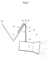
- Fig. 2 schematically shows an embodiment of the mounting device 10" when mounted to a ceiling suspended beam 20", similar to the embodiment described with reference to fig. 1 .
- the ceiling suspended beam of fig. 2 has a V-shaped cross section and is made from a sheet material with only one bend.
- the external portion 12 of the mounting device 10" is not in contact with the sheet portion 13 of the ceiling suspended beam 20", and is thus entirely suspended and stabilized by the internal portion 11, which is in contact with the inner surface of the sheet portion 13, and the load bearing portion 16, which is in contact with an upwards facing surface 18 of the sheet portion 13.
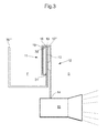
- Fig. 3 schematically shows an embodiment of the mounting device 10''' similar to the embodiment shown with reference to fig. 1 , with the difference that the internal portion 11 of the mounting device 10''' of fig. 3 comprises a protrusion 31 adapted to engage a protruding portion 32 of the sheet portion 13, on the first side thereof F, such that the mounting device 10''' is locked to the ceiling suspended beam 20''' in the upwards direction and the mounting device 10''' thus needs to be tilted counter clockwise and moved towards the inside of the channel 20''', such that the protrusion 31 can pass the protruding portion 32 of the sheet portion 13, such that the mounting device 10''' can be removed from the ceiling suspended beam 20'''.
- the internal portion 11 of the mounting device 10''' of fig. 3 comprises a protrusion 31 adapted to engage a protruding portion 32 of the sheet portion 13, on the first side thereof F, such that the mounting device 10''' is locked to the ceiling suspended beam 20''' in the
- Fig. 4 schematically shows an embodiment of the mounting device 10'''' similar to the embodiment shown in fig. 1 , the difference being that the ceiling suspended beam 20''''' has an L-shaped cross-section and thus do not form a channel.
- the embodiment of fig. 4 shows that the shape of the ceiling suspended beam 20'''' is not crucial to the design of the mounting device 10'''' and can be altered without creating a need to alter or adapt the design of the mounting device 10''''.
- Fig. 5 shows a side view of a mounting device 10 for mounting an electrical device to a ceiling suspended beam, according to one embodiment.
- the mounting device 10 comprises an internal portion 11 adapted to be positioned on a first side of a sheet portion of the ceiling suspended beam (as shown in fig. 6 ) and an external portion 12 adapted to be positioned on a second side of the sheet portion.
- the external portion 12 comprises a fixating structure 14 for fixating the electrical device (such as shown in figs 1 - 4 ).
- the fixating structure comprises a protruding pipe portion comprising an outer thread 53 adapted to receive an electrical device comprising a sleeve having an inner thread corresponding to the outer thread 53 of the fixating structure 14.
- the mounting device 10 further comprises a load bearing portion 16 connecting the internal portion 11 to the external portion 12.
- the load bearing portion 16 comprises an engaging surface 17 adapted to engage an upwards facing surface (shown as 18 in fig. 6 ) of the sheet portion of the ceiling suspended beam (as shown in fig. 6 ) and transfer at least some of the weight of the electrical device to the ceiling suspended beam.
- the internal portion 11 of the embodiment of fig. 5 further comprises an electrical connect 51, shown in the embodiment of fig. 5 as a standardized electrical plug.
- the load bearing portion 16 is hollow and comprises an integrated electrical conduit 19 extending within said hollow load bearing portion 16 from the electrical connect 51 of the internal portion 11 to the fixating structure 14 of the external portion 12, such that the electrical device can be powered via the integrated electrical conduit 19 concealed and protected by the mounting device 10.
- the electrical connect 51 of the internal portion 11 may be a standard electrical connect 51, the electrical device can be replaced together with the mounting device 10, without removing the electrical cable from the channel, which enables faster exchange of electrical devices.
- the internal portion 11 comprises a substantially rectangular portion comprising the electrical connect 51.
- the rectangular portion transfers into a slanted portion extending towards the load bearing portion 16 which in turn travels over the sheet portion of the ceiling suspended beam (as shown in fig. 6 ) and turns downwards transferring into the external portion 12 comprising a planar surface P1 extending vertically, aligned with a planar surface of a ceiling suspended beam (again, as shown in fig. 6 ), and a slanted planar surface P3 forming the external surface of the external portion 12.
- the slanted planar surface P3 extends until the slanted planar surface P3 reaches the lowermost portion of the external portion 12 which is substantially rectangular and comprises the threaded 53 fixating structure 14.
- the load bearing portion 16 being placed external to the ceiling suspended beam is to be understood as the load bearing portion 16 not travelling through a hole of the ceiling suspended beam, which means that the mounting device 10 can be removed from the ceiling suspended beam while remaining intact.
- the mounting device 10 of the embodiment shown in fig. 5 further comprises a protrusion 31 adapted to engage a protruding portion of the sheet portion of the ceiling suspended beam (shown as 32 in fig. 6 ), such that the mounting device 10 is locked to the ceiling suspended beam in the upwards (vertical) direction and the mounting device 10 thus needs to be tilted counter clockwise and moved to the left, such that the protrusion 31 clears the protruding portion of the sheet portion, such that the mounting device 10 can be removed from the ceiling suspended beam.
- a protrusion 31 adapted to engage a protruding portion of the sheet portion of the ceiling suspended beam (shown as 32 in fig. 6 ), such that the mounting device 10 is locked to the ceiling suspended beam in the upwards (vertical) direction and the mounting device 10 thus needs to be tilted counter clockwise and moved to the left, such that the protrusion 31 clears the protruding portion of the sheet portion, such that the mounting device 10 can be removed from the ceiling suspended beam.
- Fig. 6 shows the mounting device 10 according to the embodiment described with reference to fig. 5 , when mounted to a ceiling suspended beam 20.
- the engaging surface (shown as 17 in fig. 5 ) of the load bearing portion 16 is adapted to engage the upwards facing edge surface 18 of the sheet portion 13 along a longitudinal extension L of the ceiling suspended beam 20.
- the mounting device further comprises a protrusion (in fig. 6 concealed by the sheet portion 13) adapted to engage a protruding portion 32 of the sheet portion 13 of the ceiling suspended beam 20, which is a bent portion of the upper most portion of the sheet portion 13 which is somewhat slanted towards the inside and bottom of the channel, at a proximal angle to the sheet portion of 45°.
- a protrusion in fig. 6 concealed by the sheet portion 13
- the mounting device 10 is locked to the ceiling suspended beam 20 in the upwards (vertical) direction and the mounting device 10 thus needs to be tilted counter clockwise and moved to the left in fig.
- the mounting device 10 When being mounted, and thus vertically locked, the mounting device 10 may still be moved horizontally in the longitudinal extension L of the ceiling suspended beam 20, and the position of electrical devices mounted to the ceiling suspended beam 20 can thus be adjusted without the removal of the mounting device 10 from the ceiling suspended beam 20.
- the internal portion, load bearing portion and external portion are made from the same piece of homogenous material, which for example could be a polymer or metal material casted to form the mounting device.
- the mounting device is made from two casted portions 54a, 54b which are joined by means of screws.
- the hollow inside, in which the electrical conduit extends can thus be accessed by separating the two casted portions 54a, 54b.
- the mounting device 10 is made as a single piece from the same material and that access to the hollow inside of the mounting device is made possible by means of an access opening or small hatch in the mounting device 10.
- the electrical connect 51 positioned on the inside of the channel formed by the beam 20 may be connected to electrical cables adapted to be placed in the channel and connected to a power source, such as grid connection and/or a transformer or a battery.
- the mounting device 10 thus keeps cables securely placed inside of the channel and securely transfers electrical power from inside of the channel to an electrical device fixated to the mounting device 10.
Landscapes
- Engineering & Computer Science (AREA)
- General Engineering & Computer Science (AREA)
- Architecture (AREA)
- Physics & Mathematics (AREA)
- Electromagnetism (AREA)
- Civil Engineering (AREA)
- Structural Engineering (AREA)
- Installation Of Indoor Wiring (AREA)
Abstract
Description
- The present invention relates to mounting devices for mounting electrical devices to a ceiling.
- An inner ceiling system for commercial and industrial applications typically consists of a plurality of ceiling suspended beams positioned at a distance from the actual ceiling, placed under elements of air-conditioning, plumbing and electrical installations.
- The inner ceiling system many times also serve as suspension system for electrical device, such as lighting devices and loud speakers, in which case the ceiling suspended beams serve as channels hiding the electrical cables.
- As the electrical devices suspended in the ceiling suspended beams typically are placed beneath the ceiling suspended beams, cables needs to travel from the secure placing in the channel to the electrical devices suspended under the ceiling suspended beams. These electrical cables create cable loops in which other objects may be trapped.
- Also, as the electrical cables are exposed, they may be injured by for example forklifts or melted by for example hot spotlight, which may cause short circuits or in the worst case that maintenance personnel receives electrical shocks when contacting the electrical devices or ceiling suspended beams.
- A mounting device for mounting an electrical device to a ceiling suspended beam is provided. The mounting device comprises an internal portion adapted to be positioned on a first side of a sheet portion of the ceiling suspended beam and an external portion adapted to be positioned on a second side of the sheet portion of the ceiling suspended beam. The external portion comprises a fixating structure for fixating the electrical device.
- The mounting device further comprises a load bearing portion, adapted to be placed external to the ceiling suspended beam, connecting the internal portion to the external portion. The load bearing portion comprises an engaging surface adapted to engage an upwards facing edge surface of the sheet portion of the ceiling suspended beam and transfer at least some of the weight of the electrical device to the ceiling suspended beam. The load bearing portion of the mounting device is hollow and comprises an integrated electrical conduit extending within said hollow load bearing portion from the internal portion to the external portion.
- By the load bearing portion comprising an electrical conduit, electrical power can be transferred from the internal portion to the external portion while the electrical conduit remains concealed and protected by the mounting device.
- According to one embodiment, the mounting device is adapted to be mounted to a ceiling suspended beam being a channel, which may be a channel with a U-shaped cross-section, adapted to contain electrical cables, such that the cables remain protected and concealed in the channel while supplying electrical power to electrical devices mounted by means of the mounting device.
- According to one embodiment, the mounting device is adapted to be mounted to a sheet portion having the first side being located on the inside of the channel, and the second side being located on the outside of the channel.
- According to one embodiment of the mounting device, the integrated electrical conduit is connected to an electrical connect integrated in the internal portion, such that the integrated electrical conduit can be connected to a power source. As the electrical connect may be a standard electrical connect, the electrical device can be replaced together with the mounting device without removing the electrical cable from the channel, which enables faster exchange of electrical devices.
- According to one embodiment, the electrical device is an electrical lighting device.
- According to one embodiment, the internal portion comprises a protrusion adapted to engage a protruding portion of the sheet portion, on the first side thereof, such that the mounting device is locked to the ceiling suspended beam at least in an upwards direction, which enables the mounting device to be moved along the ceiling suspended beam, while remaining locked to the ceiling suspended beam.
- According to one embodiment, the external portion of the mounting device comprises a planar surface adapted to engage a planar surface on the second side of the sheet portion of the ceiling suspended beam, such that the mounting device is stabilized by the planar surface of the ceiling suspended beam.
- According to one embodiment, the engaging surface of the load bearing portion is adapted to engage the upwards facing surface of the sheet portion along a longitudinal extension of the ceiling suspended beam, such that the mounting device can be suspended by the upwards facing surface of the ceiling suspended beam while being movable along the longitudinal extension of the beam.
- According to one embodiment, at least a portion of the internal portion, the external portion and the load bearing portion are portions of the same piece of material.
- Please note that the embodiments herein could be combined in any way unless clearly contradictory.
- The invention is now described, by way of example, with reference to the accompanying drawings, in which:
-
Fig. 1 is a schematic side view of a mounting device according to one embodiment, when mounted to a ceiling suspended beam having a U-shaped cross-section. -
Fig. 2 is a schematic side view of a mounting device according to one embodiment, when mounted to a ceiling suspended beam having a V-shaped cross-section. -
Fig. 3 is a schematic side view of a mounting device according to an embodiment in which the mounting device is locked to a ceiling suspended beam in the vertical direction. -
Fig. 4 is a schematic side view of a mounting device according to one embodiment, when mounted to a ceiling suspended beam having a L-shaped cross-section. -
Fig. 5 is a detailed side view of a mounting device comprising an electrical connect and a fixating structure. -
Fig. 6 is a detailed elevated perspective view of the mounting device offig. 5 , when mounted to a ceiling suspended beam. - In the following a detailed description of embodiments of the invention will be given with reference to the accompanying drawings. It will be appreciated that the drawings are for illustration only and are not in any way restricting the scope of the invention. Thus, any references to directions, such as "up" or "down", are only referring to the directions shown in the figures. It should be noted that the features having the same reference numerals have the same function, a feature in one embodiment could thus be exchanged for a feature from another embodiment having the same reference numeral, unless clearly contradictory. The descriptions of the features having the same reference numerals should thus be seen as complementing each other in describing the fundamental idea of the feature and thereby showing the features versatility.
- To alleviate at least some of the drawbacks of mounting devices of the prior art, a mounting device for mounting an electrical device to a ceiling suspended beam is provided. A ceiling suspended beam is to be understood as any form of ceiling suspended element forming part of an inner ceiling or functioning as a structure for mounting objects. A ceiling suspended beam could for example be a beam having a U-shaped cross section and thus forming a channel in which for example electrical cables may be placed such that they are hidden from viewers watching the inner ceiling from underneath.
- An electrical device capable of being mounted using the mounting device is to be understood as any electrical device relevant to mount in a ceiling suspended beam. Electrical device includes, but are not limited to, lighting devices (such as for example spot lights), loud speakers, fans, air conditioning equipment, surveillance cameras, infrared detectors and smoke and/or heat detectors.
- The ceiling suspended beam typically consists of sheet material, such as metal (typically steel or aluminum), a polymer material or wood, which has been joined, bent, corrugated or extruded to form a beam.
- According to one embodiment, the mounting device comprises an internal portion adapted to be positioned on a first side of a sheet portion of the ceiling suspended beam, and an external portion adapted to be positioned on a second side of the sheet portion of the ceiling suspended beam. In embodiments where the beam forms a channel, the first side of the sheet portion is the side facing the inside of the channel, whereas the second side of the sheet portion is the side on the outside of the channel.
- The external portion of the mounting device comprises a fixating structure for fixating the electrical device, which for example could be a hook, a protrusion, a recess or cavity, or a portion comprising inner or outer threads.
- The external portion further comprises a load bearing portion, adapted to be placed external to the ceiling suspended beam, connecting the internal portion to the external portion. The load bearing portion in turn comprises an engaging surface adapted to engage an upwards facing surface of the sheet portion of the ceiling suspended beam, and the load bearing surface is thus adapted to transfer at least some of the weight of the electrical device to the ceiling suspended beam, such that the electrical device is at least partly suspended by the ceiling suspended beam. The load bearing portion is hollow and comprises an integrated electrical conduit extending within said hollow load bearing portion from the internal portion to the external portion. The electrical conduit can be adapted to transfer electrical energy and/or electrical signals containing information from the internal portion to the external portion. As the electrical conduit is placed within the load bearing portion, the electrical conduit is protected and concealed from the environment and already securely in place when the mounting device is mounted onto the ceiling suspended beam.
- As previously mentioned the electrical device may be at least partly suspended by the ceiling suspended beam, which could mean that the electrical device additionally is supported by for example additional hooks or fixating screws.
-
Fig. 1 shows a schematic side view of a mounting device 10' for mounting anelectrical device 15 to a ceiling suspended beam 20', according to one embodiment. The mounting 10' device comprises aninternal portion 11 adapted to be positioned on a first side F of asheet portion 13 of the ceiling suspended beam 20'and anexternal portion 12 adapted to be positioned on a second side S of thesheet portion 13 of the ceiling suspended beam 20'. Theexternal portion 12 comprises afixating structure 14 for fixating theelectrical device 15. The mounting device 10' further comprises aload bearing portion 16 placed external to the ceiling suspended beam connecting theinternal portion 11 to theexternal portion 12. Theload bearing portion 16 comprises anengaging surface 17 adapted to engage an upwards facingedge surface 18 of thesheet portion 13 of the ceiling suspended beam 20' and transfer at least some of the weight of theelectrical device 15 to the ceiling suspended beam 20'. - The
load bearing portion 16 is hollow and comprises an integratedelectrical conduit 19 extending within said hollowload bearing portion 16 from theinternal portion 11 to theexternal portion 12. - According to the embodiment shown in
fig. 1 , the ceiling suspended beam 20' is a channel 20' having a U-shaped cross section and being adapted to contain electrical cables, and the first side F of thesheet portion 13 is located on the inside of the channel 20', and the second side S of thesheet portion 13 is located on the outside of the channel 20'. - According to the embodiments described with reference to
figs. 1 - 4 , the electrical device is an electrical lighting device. However, it is equally conceivable that the electrical device is another type of electrical device, such as for example a loud speaker, a fan, air conditioning equipment, a surveillance camera, an infrared detector or a smoke or heat detector. - According to the embodiment shown in
fig. 1 , theexternal portion 12 of the mounting device 10' comprises a planar surface P1 adapted to engage a planar surface P2 on the second side S of thesheet portion 13 of the ceiling suspended beam 20'. The planar surfaces P1, P2 engages each other when the mounting device is at rest in its mounting position, such that theelectrical device 15 is stabilized by the connection of the planar surfaces and suspended in the ceiling suspended beam 20'. -
Fig. 2 schematically shows an embodiment of the mountingdevice 10" when mounted to a ceiling suspendedbeam 20", similar to the embodiment described with reference tofig. 1 . The difference being that the ceiling suspended beam offig. 2 has a V-shaped cross section and is made from a sheet material with only one bend. In the embodiment offig. 2 theexternal portion 12 of the mountingdevice 10" is not in contact with thesheet portion 13 of the ceiling suspendedbeam 20", and is thus entirely suspended and stabilized by theinternal portion 11, which is in contact with the inner surface of thesheet portion 13, and theload bearing portion 16, which is in contact with an upwards facingsurface 18 of thesheet portion 13. -
Fig. 3 schematically shows an embodiment of the mounting device 10''' similar to the embodiment shown with reference tofig. 1 , with the difference that theinternal portion 11 of the mounting device 10''' offig. 3 comprises aprotrusion 31 adapted to engage a protrudingportion 32 of thesheet portion 13, on the first side thereof F, such that the mounting device 10''' is locked to the ceiling suspended beam 20''' in the upwards direction and the mounting device 10''' thus needs to be tilted counter clockwise and moved towards the inside of the channel 20''', such that theprotrusion 31 can pass the protrudingportion 32 of thesheet portion 13, such that the mounting device 10''' can be removed from the ceiling suspended beam 20'''. -
Fig. 4 schematically shows an embodiment of the mounting device 10'''' similar to the embodiment shown infig. 1 , the difference being that the ceiling suspended beam 20'''' has an L-shaped cross-section and thus do not form a channel. The embodiment offig. 4 shows that the shape of the ceiling suspended beam 20'''' is not crucial to the design of the mounting device 10'''' and can be altered without creating a need to alter or adapt the design of the mounting device 10''''. -
Fig. 5 shows a side view of a mountingdevice 10 for mounting an electrical device to a ceiling suspended beam, according to one embodiment. The mountingdevice 10 comprises aninternal portion 11 adapted to be positioned on a first side of a sheet portion of the ceiling suspended beam (as shown infig. 6 ) and anexternal portion 12 adapted to be positioned on a second side of the sheet portion. - The
external portion 12 comprises a fixatingstructure 14 for fixating the electrical device (such as shown infigs 1 - 4 ). In the embodiment shown infig. 5 , the fixating structure comprises a protruding pipe portion comprising anouter thread 53 adapted to receive an electrical device comprising a sleeve having an inner thread corresponding to theouter thread 53 of the fixatingstructure 14. - The mounting
device 10 further comprises aload bearing portion 16 connecting theinternal portion 11 to theexternal portion 12. Theload bearing portion 16 comprises an engagingsurface 17 adapted to engage an upwards facing surface (shown as 18 infig. 6 ) of the sheet portion of the ceiling suspended beam (as shown infig. 6 ) and transfer at least some of the weight of the electrical device to the ceiling suspended beam. Theinternal portion 11 of the embodiment offig. 5 further comprises anelectrical connect 51, shown in the embodiment offig. 5 as a standardized electrical plug. Theload bearing portion 16 is hollow and comprises an integratedelectrical conduit 19 extending within said hollowload bearing portion 16 from theelectrical connect 51 of theinternal portion 11 to the fixatingstructure 14 of theexternal portion 12, such that the electrical device can be powered via the integratedelectrical conduit 19 concealed and protected by the mountingdevice 10. - As the
electrical connect 51 of theinternal portion 11 may be a standardelectrical connect 51, the electrical device can be replaced together with the mountingdevice 10, without removing the electrical cable from the channel, which enables faster exchange of electrical devices. - Turning to the structure of the mounting
device 10, theinternal portion 11 comprises a substantially rectangular portion comprising theelectrical connect 51. The rectangular portion transfers into a slanted portion extending towards theload bearing portion 16 which in turn travels over the sheet portion of the ceiling suspended beam (as shown infig. 6 ) and turns downwards transferring into theexternal portion 12 comprising a planar surface P1 extending vertically, aligned with a planar surface of a ceiling suspended beam (again, as shown infig. 6 ), and a slanted planar surface P3 forming the external surface of theexternal portion 12. The slanted planar surface P3 extends until the slanted planar surface P3 reaches the lowermost portion of theexternal portion 12 which is substantially rectangular and comprises the threaded 53 fixatingstructure 14. Theload bearing portion 16 being placed external to the ceiling suspended beam is to be understood as theload bearing portion 16 not travelling through a hole of the ceiling suspended beam, which means that the mountingdevice 10 can be removed from the ceiling suspended beam while remaining intact. - The mounting
device 10 of the embodiment shown infig. 5 further comprises aprotrusion 31 adapted to engage a protruding portion of the sheet portion of the ceiling suspended beam (shown as 32 infig. 6 ), such that the mountingdevice 10 is locked to the ceiling suspended beam in the upwards (vertical) direction and the mountingdevice 10 thus needs to be tilted counter clockwise and moved to the left, such that theprotrusion 31 clears the protruding portion of the sheet portion, such that the mountingdevice 10 can be removed from the ceiling suspended beam. -
Fig. 6 shows the mountingdevice 10 according to the embodiment described with reference tofig. 5 , when mounted to a ceiling suspendedbeam 20. The engaging surface (shown as 17 infig. 5 ) of theload bearing portion 16 is adapted to engage the upwards facingedge surface 18 of thesheet portion 13 along a longitudinal extension L of the ceiling suspendedbeam 20. - As shown in
fig. 5 , the mounting device further comprises a protrusion (infig. 6 concealed by the sheet portion 13) adapted to engage a protrudingportion 32 of thesheet portion 13 of the ceiling suspendedbeam 20, which is a bent portion of the upper most portion of thesheet portion 13 which is somewhat slanted towards the inside and bottom of the channel, at a proximal angle to the sheet portion of 45°. By means of theprotrusions device 10 is locked to the ceiling suspendedbeam 20 in the upwards (vertical) direction and the mountingdevice 10 thus needs to be tilted counter clockwise and moved to the left infig. 6 (towards the inside of the channel of the beam 20), such that the protrusion of the mountingdevice 10 clears the protrudingportion 32 of thesheet portion 13, such that the mounting device can be removed from the ceiling suspended beam. When being mounted, and thus vertically locked, the mountingdevice 10 may still be moved horizontally in the longitudinal extension L of the ceiling suspendedbeam 20, and the position of electrical devices mounted to the ceiling suspendedbeam 20 can thus be adjusted without the removal of the mountingdevice 10 from the ceiling suspendedbeam 20. - According to the embodiment of the mounting device shown in
figs. 5 and6 , the internal portion, load bearing portion and external portion are made from the same piece of homogenous material, which for example could be a polymer or metal material casted to form the mounting device. In the particular embodiment shown infig. 6 , the mounting device is made from twocasted portions fig. 5 ), can thus be accessed by separating the twocasted portions device 10 is made as a single piece from the same material and that access to the hollow inside of the mounting device is made possible by means of an access opening or small hatch in the mountingdevice 10. - The
electrical connect 51 positioned on the inside of the channel formed by thebeam 20 may be connected to electrical cables adapted to be placed in the channel and connected to a power source, such as grid connection and/or a transformer or a battery. The mountingdevice 10 thus keeps cables securely placed inside of the channel and securely transfers electrical power from inside of the channel to an electrical device fixated to the mountingdevice 10. - Any detailed description should be interpreted in its broadest outline as a general summary of the invention, and please note that any embodiment or part of embodiment could be combined in any way unless clearly contradictory.
Claims (10)
- Mounting device (10) for mounting an electrical device (15) to a ceiling suspended beam (20), the mounting device comprising:- an internal portion (11) adapted to be positioned on a first side (F) of a sheet portion (13) of the ceiling suspended beam (20),- an external portion (12) adapted to be positioned on a second side (S) of the sheet portion (13) of the ceiling suspended beam (20), the external portion (12) comprising a fixating structure (14) for fixating the electrical device (15), and- a load bearing portion (16) adapted to be placed external to the ceiling suspended beam (20), connecting the internal portion (11) to the external portion (12), wherein the load bearing portion (16) comprises an engaging surface (17) adapted to engage an upwards facing edge surface (18) of the sheet portion (13) of the ceiling suspended beam (20) and transfer at least some of the weight of the electrical device (15) to the ceiling suspended beam (20), characterized in that the load bearing portion (16) is hollow and comprises an integrated electrical conduit (19) extending within said hollow load bearing portion (16) from the internal portion (11) to the external portion (12).
- The mounting device according to claim 1, wherein the mounting device is adapted to be mounted to a ceiling suspended beam (20) being a channel adapted to contain electrical cables.
- The mounting device according to claim 2, wherein the mounting device is adapted to be mounted to a sheet portion (13) having the first side (F) being located on the inside of the channel, and the second side (S) being located on the outside of the channel.
- The mounting device according to any one of claims 2 and 3, wherein the mounting device is adapted to be mounted to a channel having a substantially U-shaped cross-section
- The mounting device according to any one of the preceding claims, wherein the integrated electrical conduit (19) is connected to an electrical connect (52) integrated in the internal portion (11), such that the integrated electrical conduit (19) can be connected to a power source.
- The mounting device according to any one of the preceding claims, wherein the electrical device (15) is an electrical lighting device (15).
- The mounting device according to any one of the preceding claims, wherein the internal portion (11) comprises a protrusion (31) adapted to engage a protruding portion (32) of the sheet portion (13), on the first side (F) thereof, such that the mounting device (10) is locked to the ceiling suspended beam (20) at least in an upwards direction
- The mounting device according to any one of the preceding claims, wherein the external portion (12) comprises a planar surface (P1) adapted to engage a planar surface (P2) on the second side (S) of the sheet portion (13) of the ceiling suspended beam (20).
- The mounting device according to any one of the preceding claims, wherein the engaging surface (17) of the load bearing portion (16) is adapted to engage the upwards facing edge surface (18) of the sheet portion (13) along a longitudinal extension (L) of the ceiling suspended beam (20).
- The mounting device according to any one of the preceding claims, wherein at least a portion of the internal portion (11), the external portion (12) and the load bearing portion (16) are portions of the same piece of material.
Priority Applications (1)
| Application Number | Priority Date | Filing Date | Title |
|---|---|---|---|
| EP13198934.5A EP2886947B1 (en) | 2013-12-20 | 2013-12-20 | Mounting device for mounting an electrical devcie on a ceiling beam |
Applications Claiming Priority (1)
| Application Number | Priority Date | Filing Date | Title |
|---|---|---|---|
| EP13198934.5A EP2886947B1 (en) | 2013-12-20 | 2013-12-20 | Mounting device for mounting an electrical devcie on a ceiling beam |
Publications (2)
| Publication Number | Publication Date |
|---|---|
| EP2886947A1 true EP2886947A1 (en) | 2015-06-24 |
| EP2886947B1 EP2886947B1 (en) | 2018-06-06 |
Family
ID=49918445
Family Applications (1)
| Application Number | Title | Priority Date | Filing Date |
|---|---|---|---|
| EP13198934.5A Not-in-force EP2886947B1 (en) | 2013-12-20 | 2013-12-20 | Mounting device for mounting an electrical devcie on a ceiling beam |
Country Status (1)
| Country | Link |
|---|---|
| EP (1) | EP2886947B1 (en) |
Citations (9)
| Publication number | Priority date | Publication date | Assignee | Title |
|---|---|---|---|---|
| US2712590A (en) * | 1953-03-17 | 1955-07-05 | James W Doble | Portable heater |
| US3429538A (en) * | 1967-04-11 | 1969-02-25 | Natale Machine & Tool Co | Lamp bracket assembly |
| US4122762A (en) * | 1977-03-07 | 1978-10-31 | Williams Arthur C | Air-slot spacer clip |
| CA1113913A (en) * | 1981-03-04 | 1981-12-08 | Jean B. Le May | Clip for hanging articles from suspended ceilings |
| US4971279A (en) * | 1989-07-03 | 1990-11-20 | George Warren T | Hanger clip |
| JPH0993840A (en) * | 1995-09-28 | 1997-04-04 | Matsushita Electric Works Ltd | Non-connection feeder structure in system ceiling |
| US6479750B1 (en) * | 2000-02-14 | 2002-11-12 | Planet Wattohm | Adapter for interconnecting two wiring ducts on opposite sides of a suspended ceiling |
| US6565048B1 (en) * | 1999-08-03 | 2003-05-20 | Thomas & Betts International, Inc. | Cable support bracket assembly |
| US20130207552A1 (en) * | 2010-10-22 | 2013-08-15 | Koninklijke Philips Electronics N.V. | Integral troffer motion detector |
Family Cites Families (2)
| Publication number | Priority date | Publication date | Assignee | Title |
|---|---|---|---|---|
| US1222669A (en) * | 1916-05-03 | 1917-04-17 | John W Purnell | Electric bath-tub heater. |
| US2789201A (en) * | 1954-05-03 | 1957-04-16 | Sherwin George Frank | Immersion heaters for bathroom tanks |
-
2013
- 2013-12-20 EP EP13198934.5A patent/EP2886947B1/en not_active Not-in-force
Patent Citations (9)
| Publication number | Priority date | Publication date | Assignee | Title |
|---|---|---|---|---|
| US2712590A (en) * | 1953-03-17 | 1955-07-05 | James W Doble | Portable heater |
| US3429538A (en) * | 1967-04-11 | 1969-02-25 | Natale Machine & Tool Co | Lamp bracket assembly |
| US4122762A (en) * | 1977-03-07 | 1978-10-31 | Williams Arthur C | Air-slot spacer clip |
| CA1113913A (en) * | 1981-03-04 | 1981-12-08 | Jean B. Le May | Clip for hanging articles from suspended ceilings |
| US4971279A (en) * | 1989-07-03 | 1990-11-20 | George Warren T | Hanger clip |
| JPH0993840A (en) * | 1995-09-28 | 1997-04-04 | Matsushita Electric Works Ltd | Non-connection feeder structure in system ceiling |
| US6565048B1 (en) * | 1999-08-03 | 2003-05-20 | Thomas & Betts International, Inc. | Cable support bracket assembly |
| US6479750B1 (en) * | 2000-02-14 | 2002-11-12 | Planet Wattohm | Adapter for interconnecting two wiring ducts on opposite sides of a suspended ceiling |
| US20130207552A1 (en) * | 2010-10-22 | 2013-08-15 | Koninklijke Philips Electronics N.V. | Integral troffer motion detector |
Also Published As
| Publication number | Publication date |
|---|---|
| EP2886947B1 (en) | 2018-06-06 |
Similar Documents
| Publication | Publication Date | Title |
|---|---|---|
| US10408396B2 (en) | Junction box for regressed light module | |
| US9732904B1 (en) | Adjustable hanger bar assembly for luminaires | |
| US7154040B1 (en) | Support bracket for electrical junction box | |
| US10281122B2 (en) | Luminaire junction box housing | |
| US9739464B2 (en) | Plaster frame for luminaires | |
| US9239131B1 (en) | Adjustable hanger bars with detachment stop | |
| US11050230B1 (en) | Electrical box for mounting an electrical device or fixture on a suspended ceiling T-bar or intersection of a T-bar grid | |
| US20090244880A1 (en) | Concealed emergency lighting equipment with complete retrofit housing and method of installation | |
| US7673842B2 (en) | Captive retaining spring | |
| US20140029271A1 (en) | Fire barrier recesssed lighting fixture | |
| US9157619B1 (en) | Reversible pole or wall mounting bracket | |
| KR101589365B1 (en) | Lighting device | |
| US8393763B2 (en) | Thermal insulation detector | |
| EP2886947A1 (en) | Mounting device for mounting an electrical devcie on a ceiling beam | |
| US20200032955A1 (en) | Apparatuses Including Fixtures and/or Fixture Mounts and Related Methods | |
| KR101522389B1 (en) | Raceway for installing lighting apparatus or CCTV camera | |
| US10571094B2 (en) | Movable tray for a suspended light fixture | |
| US11901718B1 (en) | Mono-point ceiling suspended device connector with integral plumbing and orientation alignment mechanism | |
| US20250180189A1 (en) | Fire-rated downlight housing | |
| KR20190053376A (en) | Protection duct for cable | |
| KR100726424B1 (en) | Surveillance Camera Fixture | |
| EP3382276A1 (en) | Light | |
| US20160238233A1 (en) | Modular light fixture | |
| KR101621351B1 (en) | Distributing case installed in an overhead electric power line | |
| EP3587692B1 (en) | System for partitioning a space |
Legal Events
| Date | Code | Title | Description |
|---|---|---|---|
| PUAI | Public reference made under article 153(3) epc to a published international application that has entered the european phase |
Free format text: ORIGINAL CODE: 0009012 |
|
| 17P | Request for examination filed |
Effective date: 20131220 |
|
| AK | Designated contracting states |
Kind code of ref document: A1 Designated state(s): AL AT BE BG CH CY CZ DE DK EE ES FI FR GB GR HR HU IE IS IT LI LT LU LV MC MK MT NL NO PL PT RO RS SE SI SK SM TR |
|
| AX | Request for extension of the european patent |
Extension state: BA ME |
|
| R17P | Request for examination filed (corrected) |
Effective date: 20151216 |
|
| RBV | Designated contracting states (corrected) |
Designated state(s): AL AT BE BG CH CY CZ DE DK EE ES FI FR GB GR HR HU IE IS IT LI LT LU LV MC MK MT NL NO PL PT RO RS SE SI SK SM TR |
|
| STAA | Information on the status of an ep patent application or granted ep patent |
Free format text: STATUS: EXAMINATION IS IN PROGRESS |
|
| 17Q | First examination report despatched |
Effective date: 20170214 |
|
| GRAP | Despatch of communication of intention to grant a patent |
Free format text: ORIGINAL CODE: EPIDOSNIGR1 |
|
| STAA | Information on the status of an ep patent application or granted ep patent |
Free format text: STATUS: GRANT OF PATENT IS INTENDED |
|
| GRAJ | Information related to disapproval of communication of intention to grant by the applicant or resumption of examination proceedings by the epo deleted |
Free format text: ORIGINAL CODE: EPIDOSDIGR1 |
|
| STAA | Information on the status of an ep patent application or granted ep patent |
Free format text: STATUS: EXAMINATION IS IN PROGRESS |
|
| INTG | Intention to grant announced |
Effective date: 20171205 |
|
| INTC | Intention to grant announced (deleted) | ||
| GRAP | Despatch of communication of intention to grant a patent |
Free format text: ORIGINAL CODE: EPIDOSNIGR1 |
|
| STAA | Information on the status of an ep patent application or granted ep patent |
Free format text: STATUS: GRANT OF PATENT IS INTENDED |
|
| INTG | Intention to grant announced |
Effective date: 20180213 |
|
| GRAS | Grant fee paid |
Free format text: ORIGINAL CODE: EPIDOSNIGR3 |
|
| GRAA | (expected) grant |
Free format text: ORIGINAL CODE: 0009210 |
|
| STAA | Information on the status of an ep patent application or granted ep patent |
Free format text: STATUS: THE PATENT HAS BEEN GRANTED |
|
| AK | Designated contracting states |
Kind code of ref document: B1 Designated state(s): AL AT BE BG CH CY CZ DE DK EE ES FI FR GB GR HR HU IE IS IT LI LT LU LV MC MK MT NL NO PL PT RO RS SE SI SK SM TR |
|
| REG | Reference to a national code |
Ref country code: GB Ref legal event code: FG4D |
|
| REG | Reference to a national code |
Ref country code: CH Ref legal event code: EP Ref country code: AT Ref legal event code: REF Ref document number: 1006497 Country of ref document: AT Kind code of ref document: T Effective date: 20180615 |
|
| REG | Reference to a national code |
Ref country code: IE Ref legal event code: FG4D |
|
| REG | Reference to a national code |
Ref country code: DE Ref legal event code: R096 Ref document number: 602013038515 Country of ref document: DE |
|
| REG | Reference to a national code |
Ref country code: SE Ref legal event code: TRGR |
|
| REG | Reference to a national code |
Ref country code: NL Ref legal event code: MP Effective date: 20180606 |
|
| REG | Reference to a national code |
Ref country code: LT Ref legal event code: MG4D |
|
| PG25 | Lapsed in a contracting state [announced via postgrant information from national office to epo] |
Ref country code: LT Free format text: LAPSE BECAUSE OF FAILURE TO SUBMIT A TRANSLATION OF THE DESCRIPTION OR TO PAY THE FEE WITHIN THE PRESCRIBED TIME-LIMIT Effective date: 20180606 Ref country code: CY Free format text: LAPSE BECAUSE OF FAILURE TO SUBMIT A TRANSLATION OF THE DESCRIPTION OR TO PAY THE FEE WITHIN THE PRESCRIBED TIME-LIMIT Effective date: 20180606 Ref country code: ES Free format text: LAPSE BECAUSE OF FAILURE TO SUBMIT A TRANSLATION OF THE DESCRIPTION OR TO PAY THE FEE WITHIN THE PRESCRIBED TIME-LIMIT Effective date: 20180606 Ref country code: BG Free format text: LAPSE BECAUSE OF FAILURE TO SUBMIT A TRANSLATION OF THE DESCRIPTION OR TO PAY THE FEE WITHIN THE PRESCRIBED TIME-LIMIT Effective date: 20180906 Ref country code: NO Free format text: LAPSE BECAUSE OF FAILURE TO SUBMIT A TRANSLATION OF THE DESCRIPTION OR TO PAY THE FEE WITHIN THE PRESCRIBED TIME-LIMIT Effective date: 20180906 Ref country code: FI Free format text: LAPSE BECAUSE OF FAILURE TO SUBMIT A TRANSLATION OF THE DESCRIPTION OR TO PAY THE FEE WITHIN THE PRESCRIBED TIME-LIMIT Effective date: 20180606 |
|
| PG25 | Lapsed in a contracting state [announced via postgrant information from national office to epo] |
Ref country code: GR Free format text: LAPSE BECAUSE OF FAILURE TO SUBMIT A TRANSLATION OF THE DESCRIPTION OR TO PAY THE FEE WITHIN THE PRESCRIBED TIME-LIMIT Effective date: 20180907 Ref country code: LV Free format text: LAPSE BECAUSE OF FAILURE TO SUBMIT A TRANSLATION OF THE DESCRIPTION OR TO PAY THE FEE WITHIN THE PRESCRIBED TIME-LIMIT Effective date: 20180606 Ref country code: HR Free format text: LAPSE BECAUSE OF FAILURE TO SUBMIT A TRANSLATION OF THE DESCRIPTION OR TO PAY THE FEE WITHIN THE PRESCRIBED TIME-LIMIT Effective date: 20180606 Ref country code: RS Free format text: LAPSE BECAUSE OF FAILURE TO SUBMIT A TRANSLATION OF THE DESCRIPTION OR TO PAY THE FEE WITHIN THE PRESCRIBED TIME-LIMIT Effective date: 20180606 |
|
| REG | Reference to a national code |
Ref country code: AT Ref legal event code: MK05 Ref document number: 1006497 Country of ref document: AT Kind code of ref document: T Effective date: 20180606 |
|
| PG25 | Lapsed in a contracting state [announced via postgrant information from national office to epo] |
Ref country code: NL Free format text: LAPSE BECAUSE OF FAILURE TO SUBMIT A TRANSLATION OF THE DESCRIPTION OR TO PAY THE FEE WITHIN THE PRESCRIBED TIME-LIMIT Effective date: 20180606 |
|
| PG25 | Lapsed in a contracting state [announced via postgrant information from national office to epo] |
Ref country code: PL Free format text: LAPSE BECAUSE OF FAILURE TO SUBMIT A TRANSLATION OF THE DESCRIPTION OR TO PAY THE FEE WITHIN THE PRESCRIBED TIME-LIMIT Effective date: 20180606 Ref country code: SK Free format text: LAPSE BECAUSE OF FAILURE TO SUBMIT A TRANSLATION OF THE DESCRIPTION OR TO PAY THE FEE WITHIN THE PRESCRIBED TIME-LIMIT Effective date: 20180606 Ref country code: RO Free format text: LAPSE BECAUSE OF FAILURE TO SUBMIT A TRANSLATION OF THE DESCRIPTION OR TO PAY THE FEE WITHIN THE PRESCRIBED TIME-LIMIT Effective date: 20180606 Ref country code: CZ Free format text: LAPSE BECAUSE OF FAILURE TO SUBMIT A TRANSLATION OF THE DESCRIPTION OR TO PAY THE FEE WITHIN THE PRESCRIBED TIME-LIMIT Effective date: 20180606 Ref country code: IS Free format text: LAPSE BECAUSE OF FAILURE TO SUBMIT A TRANSLATION OF THE DESCRIPTION OR TO PAY THE FEE WITHIN THE PRESCRIBED TIME-LIMIT Effective date: 20181006 Ref country code: AT Free format text: LAPSE BECAUSE OF FAILURE TO SUBMIT A TRANSLATION OF THE DESCRIPTION OR TO PAY THE FEE WITHIN THE PRESCRIBED TIME-LIMIT Effective date: 20180606 Ref country code: EE Free format text: LAPSE BECAUSE OF FAILURE TO SUBMIT A TRANSLATION OF THE DESCRIPTION OR TO PAY THE FEE WITHIN THE PRESCRIBED TIME-LIMIT Effective date: 20180606 |
|
| PG25 | Lapsed in a contracting state [announced via postgrant information from national office to epo] |
Ref country code: SM Free format text: LAPSE BECAUSE OF FAILURE TO SUBMIT A TRANSLATION OF THE DESCRIPTION OR TO PAY THE FEE WITHIN THE PRESCRIBED TIME-LIMIT Effective date: 20180606 Ref country code: IT Free format text: LAPSE BECAUSE OF FAILURE TO SUBMIT A TRANSLATION OF THE DESCRIPTION OR TO PAY THE FEE WITHIN THE PRESCRIBED TIME-LIMIT Effective date: 20180606 |
|
| REG | Reference to a national code |
Ref country code: DE Ref legal event code: R097 Ref document number: 602013038515 Country of ref document: DE |
|
| PLBE | No opposition filed within time limit |
Free format text: ORIGINAL CODE: 0009261 |
|
| STAA | Information on the status of an ep patent application or granted ep patent |
Free format text: STATUS: NO OPPOSITION FILED WITHIN TIME LIMIT |
|
| 26N | No opposition filed |
Effective date: 20190307 |
|
| PG25 | Lapsed in a contracting state [announced via postgrant information from national office to epo] |
Ref country code: SI Free format text: LAPSE BECAUSE OF FAILURE TO SUBMIT A TRANSLATION OF THE DESCRIPTION OR TO PAY THE FEE WITHIN THE PRESCRIBED TIME-LIMIT Effective date: 20180606 Ref country code: DK Free format text: LAPSE BECAUSE OF FAILURE TO SUBMIT A TRANSLATION OF THE DESCRIPTION OR TO PAY THE FEE WITHIN THE PRESCRIBED TIME-LIMIT Effective date: 20180606 |
|
| REG | Reference to a national code |
Ref country code: CH Ref legal event code: PL |
|
| GBPC | Gb: european patent ceased through non-payment of renewal fee |
Effective date: 20181220 |
|
| PG25 | Lapsed in a contracting state [announced via postgrant information from national office to epo] |
Ref country code: LU Free format text: LAPSE BECAUSE OF NON-PAYMENT OF DUE FEES Effective date: 20181220 Ref country code: MC Free format text: LAPSE BECAUSE OF FAILURE TO SUBMIT A TRANSLATION OF THE DESCRIPTION OR TO PAY THE FEE WITHIN THE PRESCRIBED TIME-LIMIT Effective date: 20180606 |
|
| REG | Reference to a national code |
Ref country code: IE Ref legal event code: MM4A |
|
| REG | Reference to a national code |
Ref country code: BE Ref legal event code: MM Effective date: 20181231 |
|
| PG25 | Lapsed in a contracting state [announced via postgrant information from national office to epo] |
Ref country code: IE Free format text: LAPSE BECAUSE OF NON-PAYMENT OF DUE FEES Effective date: 20181220 Ref country code: FR Free format text: LAPSE BECAUSE OF NON-PAYMENT OF DUE FEES Effective date: 20181231 |
|
| PG25 | Lapsed in a contracting state [announced via postgrant information from national office to epo] |
Ref country code: BE Free format text: LAPSE BECAUSE OF NON-PAYMENT OF DUE FEES Effective date: 20181231 Ref country code: AL Free format text: LAPSE BECAUSE OF FAILURE TO SUBMIT A TRANSLATION OF THE DESCRIPTION OR TO PAY THE FEE WITHIN THE PRESCRIBED TIME-LIMIT Effective date: 20180606 |
|
| PG25 | Lapsed in a contracting state [announced via postgrant information from national office to epo] |
Ref country code: GB Free format text: LAPSE BECAUSE OF NON-PAYMENT OF DUE FEES Effective date: 20181220 Ref country code: LI Free format text: LAPSE BECAUSE OF NON-PAYMENT OF DUE FEES Effective date: 20181231 Ref country code: CH Free format text: LAPSE BECAUSE OF NON-PAYMENT OF DUE FEES Effective date: 20181231 |
|
| PG25 | Lapsed in a contracting state [announced via postgrant information from national office to epo] |
Ref country code: MT Free format text: LAPSE BECAUSE OF NON-PAYMENT OF DUE FEES Effective date: 20181220 |
|
| PG25 | Lapsed in a contracting state [announced via postgrant information from national office to epo] |
Ref country code: TR Free format text: LAPSE BECAUSE OF FAILURE TO SUBMIT A TRANSLATION OF THE DESCRIPTION OR TO PAY THE FEE WITHIN THE PRESCRIBED TIME-LIMIT Effective date: 20180606 |
|
| PG25 | Lapsed in a contracting state [announced via postgrant information from national office to epo] |
Ref country code: PT Free format text: LAPSE BECAUSE OF FAILURE TO SUBMIT A TRANSLATION OF THE DESCRIPTION OR TO PAY THE FEE WITHIN THE PRESCRIBED TIME-LIMIT Effective date: 20180606 |
|
| PG25 | Lapsed in a contracting state [announced via postgrant information from national office to epo] |
Ref country code: MK Free format text: LAPSE BECAUSE OF NON-PAYMENT OF DUE FEES Effective date: 20180606 Ref country code: HU Free format text: LAPSE BECAUSE OF FAILURE TO SUBMIT A TRANSLATION OF THE DESCRIPTION OR TO PAY THE FEE WITHIN THE PRESCRIBED TIME-LIMIT; INVALID AB INITIO Effective date: 20131220 |
|
| PGFP | Annual fee paid to national office [announced via postgrant information from national office to epo] |
Ref country code: SE Payment date: 20211115 Year of fee payment: 9 Ref country code: DE Payment date: 20211116 Year of fee payment: 9 |
|
| REG | Reference to a national code |
Ref country code: DE Ref legal event code: R119 Ref document number: 602013038515 Country of ref document: DE |
|
| REG | Reference to a national code |
Ref country code: SE Ref legal event code: EUG |
|
| PG25 | Lapsed in a contracting state [announced via postgrant information from national office to epo] |
Ref country code: SE Free format text: LAPSE BECAUSE OF NON-PAYMENT OF DUE FEES Effective date: 20221221 Ref country code: DE Free format text: LAPSE BECAUSE OF NON-PAYMENT OF DUE FEES Effective date: 20230701 |