EP2886878A1 - Hydraulic control valve for construction machinery - Google Patents
Hydraulic control valve for construction machinery Download PDFInfo
- Publication number
- EP2886878A1 EP2886878A1 EP12891371.2A EP12891371A EP2886878A1 EP 2886878 A1 EP2886878 A1 EP 2886878A1 EP 12891371 A EP12891371 A EP 12891371A EP 2886878 A1 EP2886878 A1 EP 2886878A1
- Authority
- EP
- European Patent Office
- Prior art keywords
- port
- pilot
- pilot pressure
- control valve
- pump
- Prior art date
- Legal status (The legal status is an assumption and is not a legal conclusion. Google has not performed a legal analysis and makes no representation as to the accuracy of the status listed.)
- Granted
Links
Images
Classifications
-
- E—FIXED CONSTRUCTIONS
- E02—HYDRAULIC ENGINEERING; FOUNDATIONS; SOIL SHIFTING
- E02F—DREDGING; SOIL-SHIFTING
- E02F9/00—Component parts of dredgers or soil-shifting machines, not restricted to one of the kinds covered by groups E02F3/00 - E02F7/00
- E02F9/20—Drives; Control devices
- E02F9/22—Hydraulic or pneumatic drives
- E02F9/2264—Arrangements or adaptations of elements for hydraulic drives
- E02F9/2267—Valves or distributors
-
- F—MECHANICAL ENGINEERING; LIGHTING; HEATING; WEAPONS; BLASTING
- F15—FLUID-PRESSURE ACTUATORS; HYDRAULICS OR PNEUMATICS IN GENERAL
- F15B—SYSTEMS ACTING BY MEANS OF FLUIDS IN GENERAL; FLUID-PRESSURE ACTUATORS, e.g. SERVOMOTORS; DETAILS OF FLUID-PRESSURE SYSTEMS, NOT OTHERWISE PROVIDED FOR
- F15B13/00—Details of servomotor systems ; Valves for servomotor systems
- F15B13/02—Fluid distribution or supply devices characterised by their adaptation to the control of servomotors
- F15B13/04—Fluid distribution or supply devices characterised by their adaptation to the control of servomotors for use with a single servomotor
- F15B13/042—Fluid distribution or supply devices characterised by their adaptation to the control of servomotors for use with a single servomotor operated by fluid pressure
- F15B13/0426—Fluid distribution or supply devices characterised by their adaptation to the control of servomotors for use with a single servomotor operated by fluid pressure with fluid-operated pilot valves, i.e. multiple stage valves
-
- F—MECHANICAL ENGINEERING; LIGHTING; HEATING; WEAPONS; BLASTING
- F15—FLUID-PRESSURE ACTUATORS; HYDRAULICS OR PNEUMATICS IN GENERAL
- F15B—SYSTEMS ACTING BY MEANS OF FLUIDS IN GENERAL; FLUID-PRESSURE ACTUATORS, e.g. SERVOMOTORS; DETAILS OF FLUID-PRESSURE SYSTEMS, NOT OTHERWISE PROVIDED FOR
- F15B13/00—Details of servomotor systems ; Valves for servomotor systems
- F15B13/02—Fluid distribution or supply devices characterised by their adaptation to the control of servomotors
- F15B13/04—Fluid distribution or supply devices characterised by their adaptation to the control of servomotors for use with a single servomotor
- F15B13/042—Fluid distribution or supply devices characterised by their adaptation to the control of servomotors for use with a single servomotor operated by fluid pressure
- F15B13/043—Fluid distribution or supply devices characterised by their adaptation to the control of servomotors for use with a single servomotor operated by fluid pressure with electrically-controlled pilot valves
-
- E—FIXED CONSTRUCTIONS
- E02—HYDRAULIC ENGINEERING; FOUNDATIONS; SOIL SHIFTING
- E02F—DREDGING; SOIL-SHIFTING
- E02F9/00—Component parts of dredgers or soil-shifting machines, not restricted to one of the kinds covered by groups E02F3/00 - E02F7/00
- E02F9/20—Drives; Control devices
- E02F9/22—Hydraulic or pneumatic drives
- E02F9/2278—Hydraulic circuits
- E02F9/2285—Pilot-operated systems
-
- F—MECHANICAL ENGINEERING; LIGHTING; HEATING; WEAPONS; BLASTING
- F15—FLUID-PRESSURE ACTUATORS; HYDRAULICS OR PNEUMATICS IN GENERAL
- F15B—SYSTEMS ACTING BY MEANS OF FLUIDS IN GENERAL; FLUID-PRESSURE ACTUATORS, e.g. SERVOMOTORS; DETAILS OF FLUID-PRESSURE SYSTEMS, NOT OTHERWISE PROVIDED FOR
- F15B13/00—Details of servomotor systems ; Valves for servomotor systems
- F15B13/02—Fluid distribution or supply devices characterised by their adaptation to the control of servomotors
- F15B13/025—Pressure reducing valves
-
- F—MECHANICAL ENGINEERING; LIGHTING; HEATING; WEAPONS; BLASTING
- F15—FLUID-PRESSURE ACTUATORS; HYDRAULICS OR PNEUMATICS IN GENERAL
- F15B—SYSTEMS ACTING BY MEANS OF FLUIDS IN GENERAL; FLUID-PRESSURE ACTUATORS, e.g. SERVOMOTORS; DETAILS OF FLUID-PRESSURE SYSTEMS, NOT OTHERWISE PROVIDED FOR
- F15B13/00—Details of servomotor systems ; Valves for servomotor systems
- F15B13/02—Fluid distribution or supply devices characterised by their adaptation to the control of servomotors
- F15B13/04—Fluid distribution or supply devices characterised by their adaptation to the control of servomotors for use with a single servomotor
- F15B13/042—Fluid distribution or supply devices characterised by their adaptation to the control of servomotors for use with a single servomotor operated by fluid pressure
- F15B13/0422—Fluid distribution or supply devices characterised by their adaptation to the control of servomotors for use with a single servomotor operated by fluid pressure with manually-operated pilot valves, e.g. joysticks
-
- F—MECHANICAL ENGINEERING; LIGHTING; HEATING; WEAPONS; BLASTING
- F15—FLUID-PRESSURE ACTUATORS; HYDRAULICS OR PNEUMATICS IN GENERAL
- F15B—SYSTEMS ACTING BY MEANS OF FLUIDS IN GENERAL; FLUID-PRESSURE ACTUATORS, e.g. SERVOMOTORS; DETAILS OF FLUID-PRESSURE SYSTEMS, NOT OTHERWISE PROVIDED FOR
- F15B20/00—Safety arrangements for fluid actuator systems; Applications of safety devices in fluid actuator systems; Emergency measures for fluid actuator systems
- F15B20/005—Leakage; Spillage; Hose burst
-
- F—MECHANICAL ENGINEERING; LIGHTING; HEATING; WEAPONS; BLASTING
- F15—FLUID-PRESSURE ACTUATORS; HYDRAULICS OR PNEUMATICS IN GENERAL
- F15B—SYSTEMS ACTING BY MEANS OF FLUIDS IN GENERAL; FLUID-PRESSURE ACTUATORS, e.g. SERVOMOTORS; DETAILS OF FLUID-PRESSURE SYSTEMS, NOT OTHERWISE PROVIDED FOR
- F15B13/00—Details of servomotor systems ; Valves for servomotor systems
- F15B13/02—Fluid distribution or supply devices characterised by their adaptation to the control of servomotors
- F15B13/04—Fluid distribution or supply devices characterised by their adaptation to the control of servomotors for use with a single servomotor
- F15B13/042—Fluid distribution or supply devices characterised by their adaptation to the control of servomotors for use with a single servomotor operated by fluid pressure
- F15B2013/0428—Fluid distribution or supply devices characterised by their adaptation to the control of servomotors for use with a single servomotor operated by fluid pressure with switchable internal or external pilot pressure source
-
- F—MECHANICAL ENGINEERING; LIGHTING; HEATING; WEAPONS; BLASTING
- F15—FLUID-PRESSURE ACTUATORS; HYDRAULICS OR PNEUMATICS IN GENERAL
- F15B—SYSTEMS ACTING BY MEANS OF FLUIDS IN GENERAL; FLUID-PRESSURE ACTUATORS, e.g. SERVOMOTORS; DETAILS OF FLUID-PRESSURE SYSTEMS, NOT OTHERWISE PROVIDED FOR
- F15B2211/00—Circuits for servomotor systems
- F15B2211/30—Directional control
- F15B2211/305—Directional control characterised by the type of valves
- F15B2211/30525—Directional control valves, e.g. 4/3-directional control valve
-
- F—MECHANICAL ENGINEERING; LIGHTING; HEATING; WEAPONS; BLASTING
- F15—FLUID-PRESSURE ACTUATORS; HYDRAULICS OR PNEUMATICS IN GENERAL
- F15B—SYSTEMS ACTING BY MEANS OF FLUIDS IN GENERAL; FLUID-PRESSURE ACTUATORS, e.g. SERVOMOTORS; DETAILS OF FLUID-PRESSURE SYSTEMS, NOT OTHERWISE PROVIDED FOR
- F15B2211/00—Circuits for servomotor systems
- F15B2211/30—Directional control
- F15B2211/32—Directional control characterised by the type of actuation
- F15B2211/329—Directional control characterised by the type of actuation actuated by fluid pressure
-
- F—MECHANICAL ENGINEERING; LIGHTING; HEATING; WEAPONS; BLASTING
- F15—FLUID-PRESSURE ACTUATORS; HYDRAULICS OR PNEUMATICS IN GENERAL
- F15B—SYSTEMS ACTING BY MEANS OF FLUIDS IN GENERAL; FLUID-PRESSURE ACTUATORS, e.g. SERVOMOTORS; DETAILS OF FLUID-PRESSURE SYSTEMS, NOT OTHERWISE PROVIDED FOR
- F15B2211/00—Circuits for servomotor systems
- F15B2211/30—Directional control
- F15B2211/355—Pilot pressure control
-
- F—MECHANICAL ENGINEERING; LIGHTING; HEATING; WEAPONS; BLASTING
- F15—FLUID-PRESSURE ACTUATORS; HYDRAULICS OR PNEUMATICS IN GENERAL
- F15B—SYSTEMS ACTING BY MEANS OF FLUIDS IN GENERAL; FLUID-PRESSURE ACTUATORS, e.g. SERVOMOTORS; DETAILS OF FLUID-PRESSURE SYSTEMS, NOT OTHERWISE PROVIDED FOR
- F15B2211/00—Circuits for servomotor systems
- F15B2211/60—Circuit components or control therefor
- F15B2211/635—Circuits providing pilot pressure to pilot pressure-controlled fluid circuit elements
- F15B2211/6355—Circuits providing pilot pressure to pilot pressure-controlled fluid circuit elements having valve means
-
- Y—GENERAL TAGGING OF NEW TECHNOLOGICAL DEVELOPMENTS; GENERAL TAGGING OF CROSS-SECTIONAL TECHNOLOGIES SPANNING OVER SEVERAL SECTIONS OF THE IPC; TECHNICAL SUBJECTS COVERED BY FORMER USPC CROSS-REFERENCE ART COLLECTIONS [XRACs] AND DIGESTS
- Y10—TECHNICAL SUBJECTS COVERED BY FORMER USPC
- Y10T—TECHNICAL SUBJECTS COVERED BY FORMER US CLASSIFICATION
- Y10T137/00—Fluid handling
- Y10T137/7722—Line condition change responsive valves
- Y10T137/7758—Pilot or servo controlled
- Y10T137/7762—Fluid pressure type
Definitions
- the present invention relates to a hydraulic control valve for a construction machine. More particularly, the present invention relates to a hydraulic control valve for a construction machine in which when a shifting device is pressedly rotated to drive a traveling motor or the like, a secondary pilot pressure formed in proportion to the shifting amount of the shifting device can be prevented from exceeding a preset pressure of a pilot pump.
- a hydraulic control valve for a construction machine in accordance with the prior art as shown in Figs. 3 to 5 includes:
- a hydraulic circuit used for embodying a hydraulic control valve in accordance with the prior art as shown in Figs. 1 and 2 includes:
- a high pressure is generated in the main control valve 10 that controls a hydraulic fluid supplied to the hydraulic actuator 9 from the hydraulic pump 7.
- a hydraulic fluid from an external connection device e.g., a hydraulic port of the main control valve
- the secondary pilot pressure port C can back-flow to the secondary pilot pressure port C via shifting signal paths a and b, and the signal pressure path 11.
- the present invention has been made to solve the aforementioned problems occurring in the prior art, and it is an object of the present invention to provide a hydraulic control valve for a construction machine in which when a high pressure hydraulic fluid back-flows to a secondary pilot pressure port due to leakage of a hydraulic fluid in a main control valve that controls the hydraulic fluid supplied to a hydraulic actuator, a secondary pilot pressure can be maintained below a preset pressure of a relief valve for a pilot pump.
- a hydraulic control valve for a construction machine including:
- a traveling pedal may be used as the shifting device.
- an excavator may be used as the construction machine provided with the traveling pedal.
- the hydraulic control valve for a construction machine in accordance with an embodiment of the present invention as constructed above has the following advantages.
- the secondary pilot pressure can be maintained below the preset pressure of the relief valve for the pilot pump, so that damage or failure of pilot hydraulic parts is prevented, thereby ensuring reliability of the machine.
- a hydraulic control valve for a construction machine in accordance with an embodiment of the present invention as shown in Figs. 6 to 8 includes:
- a traveling pedal may be used as the shifting device 3.
- an excavator may be used as the construction machine provided with the traveling pedal.
- a configuration of the hydraulic control valve for a construction machine in accordance with the present invention is substantially the same as that of the hydraulic control valve for a construction machine in accordance with the prior art, except the pilot path 18 and the check poppet 19.
- the detailed description of the same configuration and operation thereof will be omitted to avoid redundancy, and the same elements of the hydraulic control valve are denoted by the same reference numerals.
- a main control valve 10 is shifted by the secondary pilot pressure formed in signal pressure path 11 to control a hydraulic fluid supplied to a hydraulic actuator 9 from a hydraulic pump 7, when leakage of the hydraulic fluid occurs through a gap defined between a valve body and a spool of the main control valve 10, a hydraulic fluid from a hydraulic port of the main control valve 10 can back-flow to the secondary pilot pressure port C via shifting signal paths a and b, and the signal pressure path 11.
- a high pressure hydraulic fluid of the secondary pilot pressure port C side causes the check poppet 19 the pilot path 18 to be shifted to the right on the drawing sheet so as to open the pilot path 18.
- the secondary pilot pressure port C and the port Pi for the pilot pump fluidically communicate with each other, the high pressure hydraulic fluid that has back-flowed to the secondary pilot pressure port C from the main control valve 10 is moved to a path 8a of the pilot pump 8.
- the high pressure hydraulic fluid moved to the path 8a exceeds a preset pressure
- the high pressure hydraulic fluid is drained to a hydraulic tank.
- the signal pressure path 11 can maintain the preset pressure of a relief valve 14.
- the check poppet 19 does not allow the pilot pressure to be moved toward the secondary pilot pressure port C from the port Pi for the pilot pump.
- the secondary pilot pressure formed in proportion to the shifting amount of the shifting device can be maintained below the preset pressure of the pilot pump.
Landscapes
- Engineering & Computer Science (AREA)
- General Engineering & Computer Science (AREA)
- Physics & Mathematics (AREA)
- Fluid Mechanics (AREA)
- Mechanical Engineering (AREA)
- Mining & Mineral Resources (AREA)
- Civil Engineering (AREA)
- Structural Engineering (AREA)
- Operation Control Of Excavators (AREA)
- Fluid-Pressure Circuits (AREA)
Abstract
Description
- The present invention relates to a hydraulic control valve for a construction machine. More particularly, the present invention relates to a hydraulic control valve for a construction machine in which when a shifting device is pressedly rotated to drive a traveling motor or the like, a secondary pilot pressure formed in proportion to the shifting amount of the shifting device can be prevented from exceeding a preset pressure of a pilot pump.
- A hydraulic control valve for a construction machine in accordance with the prior art as shown in
Figs. 3 to 5 includes: - a valve body 1 that includes a port Pi for a pilot pump, through which a pilot pressure is introduced, a tank port T through which the pilot pressure is drained, and a secondary pilot pressure port C configured to selectively fluidically communicate with the port Pi for the pilot pump or the tank port T;
- a shifting device 3 (e.g., traveling pedal) that is rotatably mounted on the valve body 1 by means of a fixing pin 2;
- a
rod 4 that is configured to be shifted in cooperation with the shifting device 3 when the shifting device 3 is pressedly rotated ; - a
spool 5 that is configured to be shifted in response to the shifting of therod 4 to cause the port Pi for the pilot pump and the secondary pilot pressure port C to fluidically communicate with each other to set a secondary pilot pressure in proportion to a shifting amount of the shifting device 3; and - a
valve spring 6 that is configured to elastically support thespool 5 to cause the secondary pilot pressure port C and the tank port T to fluidically communicate with each other. - A hydraulic circuit used for embodying a hydraulic control valve in accordance with the prior art as shown in
Figs. 1 and 2 includes: - a main hydraulic pump 7 (hereinafter, referred to as "hydraulic pump") and a pilot pump 8, which are connected to an engine (not shown);
- a hydraulic actuator 9 (e.g., traveling motor) that is connected to the hydraulic pump 7;
- a main control valve (MCV) 10 that is installed in a path between the hydraulic pump 7 and the hydraulic actuator 9 and is configured to be shifted to control a start, a stop, and a direction change of the hydraulic actuator 9;
- a
control valve 12 that is installed in asignal pressure path 11 connected to apath 8a of the pilot pump 8 and is configured to be shifted to shift a spool of themain control valve 10 in a direction where thecontrol valve 12 is shifted; - a
pilot control valve 13 that is installed in the pilot pump 8 and thecontrol valve 12 and is configured to set a secondary pilot pressure in proportion to the pressed rotation of the shifting device 3 during the shifting of thespool 5; and - a
relief valve 14 that is installed in thepath 8a of the pilot pump 8 and is configured to set a discharge pressure of the pilot pump 8. - When the shifting device 3 is pressedly rotated about a fixing pin 2 in a counter-clockwise direction on the drawing sheet of
Fig. 7 to drive a hydraulic actuator 9, therod 4 is shifted to the bottom on the drawing sheet in cooperation with the shifting device to cause thespool 5 to be shifted to the bottom on the drawing sheet. At this point, thevalve spring 6 receives a compressive force. For this reason, a hydraulic fluid of the port Pi side for the pilot pump 8 is transferred to the secondary pilot pressure port C after sequentially passing through anorifice 15, afirst path 16, and asecond path 17 in this order, so that a secondary pilot pressure is formed in asignal pressure path 11. In other words, the secondary pilot pressure formed in thesignal pressure path 11 rises in proportion to a shifting amount of the shifting device 3 when the shifting device 3 is pressedly rotated downwardly. - As mentioned above, in case of the hydraulic control valve that forms the secondary pilot pressure in the
signal pressure path 11 in proportion to the shifting amount of the shifting device 3, a high pressure is generated in themain control valve 10 that controls a hydraulic fluid supplied to the hydraulic actuator 9 from the hydraulic pump 7. In this case, when leakage of the hydraulic fluid occurs through a gap defined between a valve body and a spool of themain control valve 10, a hydraulic fluid from an external connection device (e.g., a hydraulic port of the main control valve) connected to the secondary pilot pressure port C can back-flow to the secondary pilot pressure port C via shifting signal paths a and b, and thesignal pressure path 11. In this case, there is caused a problem in that the pilot hydraulic parts (e.g., thesignal pressure path 11, a spool cap of themain control valve 10, and the like) to which the pilot pressure is supplied are damaged or a failure thereof is induced due to the high pressure formed in the secondary pilot pressure port C. - Accordingly, the present invention has been made to solve the aforementioned problems occurring in the prior art, and it is an object of the present invention to provide a hydraulic control valve for a construction machine in which when a high pressure hydraulic fluid back-flows to a secondary pilot pressure port due to leakage of a hydraulic fluid in a main control valve that controls the hydraulic fluid supplied to a hydraulic actuator, a secondary pilot pressure can be maintained below a preset pressure of a relief valve for a pilot pump.
- To achieve the above object, in accordance with an embodiment of the present invention, there is provided a hydraulic control valve for a construction machine, including:
- a valve body including a port for a pilot pump, through which a pilot pressure is introduced, a tank port through which the pilot pressure is drained, and a secondary pilot pressure port configured to selectively fluidically communicate with the port of the pilot pump or the tank port;
- a shifting device rotatably mounted on the valve body;
- a rod configured to be shifted in cooperation with the shifting device when the shifting device is pressedly rotated;
- a pilot control valve including a spool configured to be shifted in response to the shifting of the rod to cause the port for the pilot pump and the secondary pilot pressure port to fluidically communicate with each other to set a secondary pilot pressure in proportion to a shifting amount of the shifting device;
- a valve spring configured to elastically support the spool to cause the secondary pilot pressure port and the tank port to fluidically communicate with each other;
- a pilot path including an inlet that fluidically communicates with the secondary pilot pressure port and an outlet that fluidically communicates with the port of the pilot pump ; and
- a check poppet openably or closably installed in the pilot path so as to allow for the uni-directional movement of a hydraulic fluid from the secondary pilot pressure port to the port of the pilot pump.
- In accordance with a preferred embodiment of the present invention, a traveling pedal may be used as the shifting device.
- In addition, an excavator may be used as the construction machine provided with the traveling pedal.
- The hydraulic control valve for a construction machine in accordance with an embodiment of the present invention as constructed above has the following advantages.
- Even when the high pressure hydraulic fluid back-flows to the secondary pilot pressure port due to leakage of the hydraulic fluid in the main control valve, the secondary pilot pressure can be maintained below the preset pressure of the relief valve for the pilot pump, so that damage or failure of pilot hydraulic parts is prevented, thereby ensuring reliability of the machine.
- The above objects, other features and advantages of the present invention will become more apparent by describing the preferred embodiments thereof with reference to the accompanying drawings, in which:
-
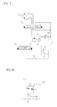
Fig. 1 is a diagram illustrating a hydraulic circuit used for embodying a hydraulic control valve for a construction machine in accordance with the prior art; -
Fig. 2 is an exploded view of a region A shown inFig. 1 ; -
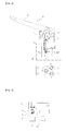
Fig. 3 is a schematic and bottom view illustrating a hydraulic control valve for a construction machine in accordance with the prior art; -
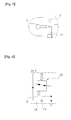
Fig. 4 is an exploded view of a region B shown inFig. 3 ; -
Fig. 5 is a cross-sectional view taken along the line A-A shown inFig. 3 ; -
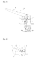
Fig. 6 is a diagram illustrating a hydraulic circuit used for embodying a hydraulic control valve for a construction machine in accordance with an embodiment of the present invention; -
Fig. 7 is a schematic view illustrating a hydraulic control valve for a construction machine in accordance with an embodiment of the present invention; and -
Fig. 8 is a cross-sectional view taken along the line B-B shown inFig. 7 . -
- 1: valve body
- 2: fixing pin
- 3: shifting device
- 4: rod
- 5: spool
- 6: valve spring
- 7: main hydraulic pump
- 8: pilot pump
- 9: hydraulic actuator
- 10: main control valve
- 11: signal pressure path
- 12: control valve
- 13: pilot control valve
- 14: relief valve
- 15: orifice
- 16: first path
- 17: second pat
- 18: pilot path
- 19: check poppet
- 20: pilot control valve
- Now, preferred embodiments of the present invention will be described in detail with reference to the accompanying drawings. The matters defined in the description, such as the detailed construction and elements, are nothing but specific details provided to assist those of ordinary skill in the art in a comprehensive understanding of the invention, and the present invention is not limited to the embodiments disclosed hereinafter.
- A hydraulic control valve for a construction machine in accordance with an embodiment of the present invention as shown in
Figs. 6 to 8 includes: - a valve body 1 that includes a port Pi for a pilot pump, through which a pilot pressure is introduced, a tank port T through which the pilot pressure is drained, and a secondary pilot pressure port C configured to selectively fluidically communicate with the port Pi for the pilot pump or the tank port T;
- a shifting device 3 that is rotatably mounted on the valve body 1 by means of a fixing pin 2;
- a
rod 4 that is configured to be shifted in cooperation with the shifting device 3 when the shifting device 3 is pressedly rotated about the fixing pin 2; - a
pilot control valve 20 that includes aspool 5 that is configured to be shifted in response to the shifting of therod 4 to cause the port Pi for the pilot pump and the secondary pilot pressure port C to fluidically communicate with each other to set a secondary pilot pressure in proportion to a shifting amount of the shifting device 3; - a
valve spring 6 that is configured to elastically support thespool 5 to cause the secondary pilot pressure port C and the tank port T to fluidically communicate with each other; - a
pilot path 18 that includes an inlet that fluidically communicates with the secondary pilot pressure port C and an outlet that fluidically communicates with the port Pi for the pilot pump ; and - a
check poppet 19 that is openably or closably installed in thepilot path 18 so as to allow for the uni-directional movement of a hydraulic fluid from the secondary pilot pressure port C to the port Pi for the pilot pump. - In accordance with a preferred embodiment of the present invention, a traveling pedal may be used as the shifting device 3.
- In addition, an excavator may be used as the construction machine provided with the traveling pedal.
- In this case, a configuration of the hydraulic control valve for a construction machine in accordance with the present invention is substantially the same as that of the hydraulic control valve for a construction machine in accordance with the prior art, except the
pilot path 18 and thecheck poppet 19. Thus, the detailed description of the same configuration and operation thereof will be omitted to avoid redundancy, and the same elements of the hydraulic control valve are denoted by the same reference numerals. - Hereinafter, the use example of a hydraulic control valve for a construction machine in accordance with an embodiment of the present invention will be described in detail with reference to the accompanying drawings.
- As shown in
Figs. 1 , and6 to 8 , when the shifting device 3 is pressedly rotated about a fixing pin 2 in a counter-clockwise direction on the drawing sheet ofFig. 7 to drive a hydraulic actuator 9, therod 4 is shifted to the bottom on the drawing sheet in cooperation with the shifting device to cause thespool 5 to be shifted to the bottom on the drawing sheet. At this point, thevalve spring 6 receives a compressive force. For this reason, a hydraulic fluid of the port Pi side for the pilot pump 8 is transferred to the secondary pilot pressure port C after sequentially passing through anorifice 15, afirst path 16, and asecond path 17 in this order, so that a secondary pilot pressure in proportion to a shifting amount of the shifting device 3 is formed in asignal pressure path 11. - In this case, in the case where a
main control valve 10 is shifted by the secondary pilot pressure formed insignal pressure path 11 to control a hydraulic fluid supplied to a hydraulic actuator 9 from a hydraulic pump 7, when leakage of the hydraulic fluid occurs through a gap defined between a valve body and a spool of themain control valve 10, a hydraulic fluid from a hydraulic port of themain control valve 10 can back-flow to the secondary pilot pressure port C via shifting signal paths a and b, and thesignal pressure path 11. - In this case, as shown in
Fig. 8 , a high pressure hydraulic fluid of the secondary pilot pressure port C side causes thecheck poppet 19 thepilot path 18 to be shifted to the right on the drawing sheet so as to open thepilot path 18. In other words, since the secondary pilot pressure port C and the port Pi for the pilot pump fluidically communicate with each other, the high pressure hydraulic fluid that has back-flowed to the secondary pilot pressure port C from themain control valve 10 is moved to apath 8a of the pilot pump 8. - Accordingly, when the pressure of the high pressure hydraulic fluid moved to the
path 8a exceeds a preset pressure, the high pressure hydraulic fluid is drained to a hydraulic tank. Thus, even when the high pressure hydraulic fluid that back-flows to the secondary pilot pressure port C from themain control valve 10, thesignal pressure path 11 can maintain the preset pressure of arelief valve 14. In the meantime, thecheck poppet 19 does not allow the pilot pressure to be moved toward the secondary pilot pressure port C from the port Pi for the pilot pump. - As mentioned above, even when leakage of the hydraulic fluid occurs due to high pressure generated in the
main control valve 10 to cause the hydraulic fluid to back-flow to the secondary pilot pressure port C, a secondary pilot pressure generated from thepilot control valve 20 maintains the preset pressure of therelief valve 14. Resultantly, it is possible to prevent damage or failure of pilot hydraulic parts due to generation of abnormal high pressure in themain control valve 10. - In accordance with the present invention having the above-mentioned configuration, when the shifting device is pressedly rotated to drive a traveling motor or the like, the secondary pilot pressure formed in proportion to the shifting amount of the shifting device can be maintained below the preset pressure of the pilot pump.
- While the present invention has been described in connection with the specific embodiments illustrated in the drawings, they are merely illustrative, and the invention is not limited to these embodiments. It is to be understood that various equivalent modifications and variations of the embodiments can be made by a person having an ordinary skill in the art without departing from the spirit and scope of the present invention. Therefore, the true technical scope of the present invention should not be defined by the above-mentioned embodiments but should be defined by the appended claims and equivalents thereof.
Claims (3)
Applications Claiming Priority (1)
| Application Number | Priority Date | Filing Date | Title |
|---|---|---|---|
| PCT/KR2012/006507 WO2014027706A1 (en) | 2012-08-16 | 2012-08-16 | Hydraulic control valve for construction machinery |
Publications (3)
| Publication Number | Publication Date |
|---|---|
| EP2886878A1 true EP2886878A1 (en) | 2015-06-24 |
| EP2886878A4 EP2886878A4 (en) | 2016-04-06 |
| EP2886878B1 EP2886878B1 (en) | 2020-12-09 |
Family
ID=50685624
Family Applications (1)
| Application Number | Title | Priority Date | Filing Date |
|---|---|---|---|
| EP12891371.2A Not-in-force EP2886878B1 (en) | 2012-08-16 | 2012-08-16 | Hydraulic control valve for construction machinery |
Country Status (6)
| Country | Link |
|---|---|
| US (1) | US9759238B2 (en) |
| EP (1) | EP2886878B1 (en) |
| KR (1) | KR101718836B1 (en) |
| CN (1) | CN104520595B (en) |
| CA (1) | CA2880733C (en) |
| WO (1) | WO2014027706A1 (en) |
Families Citing this family (2)
| Publication number | Priority date | Publication date | Assignee | Title |
|---|---|---|---|---|
| JP6475522B2 (en) * | 2015-03-13 | 2019-02-27 | 川崎重工業株式会社 | Hydraulic system |
| CN114076129B (en) * | 2020-08-11 | 2024-10-01 | 徐州徐工液压件有限公司 | Signal control valve and engineering machinery |
Family Cites Families (18)
| Publication number | Priority date | Publication date | Assignee | Title |
|---|---|---|---|---|
| GB1167703A (en) * | 1967-01-17 | 1969-10-22 | Kyoei Kaihatsu Kabushiki Kaish | A Pilot-Operated Valve Having a Short Delay in Opening |
| WO1988002071A1 (en) * | 1986-09-09 | 1988-03-24 | Hitachi Construction Machinary Co., Ltd | Valve device |
| JP2749611B2 (en) * | 1989-02-10 | 1998-05-13 | 日立建機株式会社 | Hydraulic drive using load sensing system |
| US5333449A (en) * | 1991-09-02 | 1994-08-02 | Hitachi Construction Machinery Co., Ltd. | Pressure compensating valve assembly |
| JPH08121408A (en) * | 1994-10-18 | 1996-05-14 | Nishina Kogyo Kk | Pilot valve |
| JP3670718B2 (en) * | 1995-07-10 | 2005-07-13 | 日立建機株式会社 | Hydraulic control device for hydraulic traveling vehicle |
| KR100193679B1 (en) | 1996-07-08 | 1999-06-15 | 김형벽 | Engine control of wheeled excavator |
| JP2002213609A (en) * | 2001-01-15 | 2002-07-31 | Komatsu Ltd | Hydraulic circuit |
| US6907902B2 (en) * | 2001-11-08 | 2005-06-21 | Komatsu Ltd. | Hydraulic signal output device |
| JP2005207499A (en) * | 2004-01-22 | 2005-08-04 | Hitachi Constr Mach Co Ltd | Hydraulic circuit for construction machinery |
| JP2006125627A (en) * | 2004-09-29 | 2006-05-18 | Kobelco Contstruction Machinery Ltd | Hydraulic circuit of construction machinery |
| DE102005005928A1 (en) * | 2004-12-10 | 2006-06-14 | Bosch Rexroth Aktiengesellschaft | Control arrangement e.g. for controlling hydraulic directional valve, has two pilot valves connected over control pressure pipe where actuating pressure adjusts selector valve |
| DE102006007935A1 (en) * | 2006-02-21 | 2007-10-25 | Liebherr France Sas | Control device and hydraulic pilot control |
| JP4855124B2 (en) * | 2006-04-06 | 2012-01-18 | 株式会社小松製作所 | Bulldozer, work machine and free-fall method of blade |
| KR20100012008A (en) | 2008-07-26 | 2010-02-04 | 볼보 컨스트럭션 이키프먼트 홀딩 스웨덴 에이비 | Pipe layer of having swing speed adjustable system |
| JP5203131B2 (en) * | 2008-10-21 | 2013-06-05 | 日立建機株式会社 | Hydraulic circuit for construction machinery |
| KR101088754B1 (en) * | 2009-10-20 | 2011-12-01 | 볼보 컨스트럭션 이큅먼트 에이비 | Hydraulic control valve |
| EP2644905A4 (en) | 2010-11-25 | 2018-01-10 | Volvo Construction Equipment AB | Flow control valve for construction machine |
-
2012
- 2012-08-16 KR KR1020157003721A patent/KR101718836B1/en not_active Expired - Fee Related
- 2012-08-16 CN CN201280075146.1A patent/CN104520595B/en not_active Expired - Fee Related
- 2012-08-16 WO PCT/KR2012/006507 patent/WO2014027706A1/en not_active Ceased
- 2012-08-16 US US14/419,829 patent/US9759238B2/en not_active Expired - Fee Related
- 2012-08-16 EP EP12891371.2A patent/EP2886878B1/en not_active Not-in-force
- 2012-08-16 CA CA2880733A patent/CA2880733C/en active Active
Also Published As
| Publication number | Publication date |
|---|---|
| EP2886878A4 (en) | 2016-04-06 |
| KR101718836B1 (en) | 2017-03-22 |
| US9759238B2 (en) | 2017-09-12 |
| KR20150040926A (en) | 2015-04-15 |
| EP2886878B1 (en) | 2020-12-09 |
| CA2880733C (en) | 2017-07-18 |
| CN104520595A (en) | 2015-04-15 |
| CN104520595B (en) | 2016-02-10 |
| WO2014027706A1 (en) | 2014-02-20 |
| US20150204360A1 (en) | 2015-07-23 |
| CA2880733A1 (en) | 2014-02-20 |
Similar Documents
| Publication | Publication Date | Title |
|---|---|---|
| JP6603568B2 (en) | Hydraulic drive system | |
| US9651063B2 (en) | Priority control system for construction machine | |
| US9810244B2 (en) | Flow control valve for construction machinery | |
| EP2719902A1 (en) | Hydraulic system for construction machinery | |
| US20130333367A1 (en) | Hydraulic circuit for pipe layer | |
| JP2017110672A5 (en) | ||
| US20160017898A1 (en) | Merging circuit of hydraulic apparatus | |
| US9085875B2 (en) | Hydraulic control valve for construction machinery | |
| JP2005265062A (en) | Hydraulic control device for work machine | |
| JP6514522B2 (en) | Hydraulic drive system of unloading valve and hydraulic shovel | |
| JP6463649B2 (en) | Hydraulic drive system for construction machinery | |
| EP3026181B1 (en) | Hydraulic circuit for construction machine | |
| CN107250563A (en) | Flow control valve for building machinery | |
| KR101716591B1 (en) | Fluid pressure control device for power shovel | |
| JP2017089865A (en) | Hydraulic drive | |
| US9605693B2 (en) | Hydraulic pressure control device for swing motor for construction machinery | |
| CN107532619B (en) | Fluid pressure control device | |
| CN103052755B (en) | Devices for controlling construction equipment | |
| US9759238B2 (en) | Hydraulic control valve for construction machinery | |
| WO2015162993A1 (en) | Control valve device | |
| US20170030053A1 (en) | Control device for confluence flow rate of working device for construction machinery and control method therefor | |
| JP2019010963A (en) | Steering control system | |
| JP2014040909A5 (en) | ||
| JP5768181B2 (en) | Power shovel control valve device | |
| JP2010048396A (en) | Pump control circuit of construction machine |
Legal Events
| Date | Code | Title | Description |
|---|---|---|---|
| PUAI | Public reference made under article 153(3) epc to a published international application that has entered the european phase |
Free format text: ORIGINAL CODE: 0009012 |
|
| 17P | Request for examination filed |
Effective date: 20150209 |
|
| AK | Designated contracting states |
Kind code of ref document: A1 Designated state(s): AL AT BE BG CH CY CZ DE DK EE ES FI FR GB GR HR HU IE IS IT LI LT LU LV MC MK MT NL NO PL PT RO RS SE SI SK SM TR |
|
| AX | Request for extension of the european patent |
Extension state: BA ME |
|
| DAX | Request for extension of the european patent (deleted) | ||
| REG | Reference to a national code |
Ref country code: DE Ref legal event code: R079 Ref document number: 602012073694 Country of ref document: DE Free format text: PREVIOUS MAIN CLASS: F15B0013043000 Ipc: F15B0013042000 |
|
| RA4 | Supplementary search report drawn up and despatched (corrected) |
Effective date: 20160307 |
|
| RIC1 | Information provided on ipc code assigned before grant |
Ipc: F15B 13/02 20060101ALI20160301BHEP Ipc: F15B 13/042 20060101AFI20160301BHEP Ipc: F15B 20/00 20060101ALI20160301BHEP Ipc: E02F 9/22 20060101ALI20160301BHEP |
|
| GRAP | Despatch of communication of intention to grant a patent |
Free format text: ORIGINAL CODE: EPIDOSNIGR1 |
|
| STAA | Information on the status of an ep patent application or granted ep patent |
Free format text: STATUS: GRANT OF PATENT IS INTENDED |
|
| INTG | Intention to grant announced |
Effective date: 20200803 |
|
| GRAS | Grant fee paid |
Free format text: ORIGINAL CODE: EPIDOSNIGR3 |
|
| GRAA | (expected) grant |
Free format text: ORIGINAL CODE: 0009210 |
|
| STAA | Information on the status of an ep patent application or granted ep patent |
Free format text: STATUS: THE PATENT HAS BEEN GRANTED |
|
| AK | Designated contracting states |
Kind code of ref document: B1 Designated state(s): AL AT BE BG CH CY CZ DE DK EE ES FI FR GB GR HR HU IE IS IT LI LT LU LV MC MK MT NL NO PL PT RO RS SE SI SK SM TR |
|
| REG | Reference to a national code |
Ref country code: GB Ref legal event code: FG4D |
|
| REG | Reference to a national code |
Ref country code: AT Ref legal event code: REF Ref document number: 1343737 Country of ref document: AT Kind code of ref document: T Effective date: 20201215 Ref country code: CH Ref legal event code: EP |
|
| REG | Reference to a national code |
Ref country code: DE Ref legal event code: R096 Ref document number: 602012073694 Country of ref document: DE |
|
| REG | Reference to a national code |
Ref country code: IE Ref legal event code: FG4D |
|
| PG25 | Lapsed in a contracting state [announced via postgrant information from national office to epo] |
Ref country code: GR Free format text: LAPSE BECAUSE OF FAILURE TO SUBMIT A TRANSLATION OF THE DESCRIPTION OR TO PAY THE FEE WITHIN THE PRESCRIBED TIME-LIMIT Effective date: 20210310 Ref country code: NO Free format text: LAPSE BECAUSE OF FAILURE TO SUBMIT A TRANSLATION OF THE DESCRIPTION OR TO PAY THE FEE WITHIN THE PRESCRIBED TIME-LIMIT Effective date: 20210309 Ref country code: FI Free format text: LAPSE BECAUSE OF FAILURE TO SUBMIT A TRANSLATION OF THE DESCRIPTION OR TO PAY THE FEE WITHIN THE PRESCRIBED TIME-LIMIT Effective date: 20201209 Ref country code: RS Free format text: LAPSE BECAUSE OF FAILURE TO SUBMIT A TRANSLATION OF THE DESCRIPTION OR TO PAY THE FEE WITHIN THE PRESCRIBED TIME-LIMIT Effective date: 20201209 |
|
| REG | Reference to a national code |
Ref country code: AT Ref legal event code: MK05 Ref document number: 1343737 Country of ref document: AT Kind code of ref document: T Effective date: 20201209 |
|
| PG25 | Lapsed in a contracting state [announced via postgrant information from national office to epo] |
Ref country code: SE Free format text: LAPSE BECAUSE OF FAILURE TO SUBMIT A TRANSLATION OF THE DESCRIPTION OR TO PAY THE FEE WITHIN THE PRESCRIBED TIME-LIMIT Effective date: 20201209 Ref country code: LV Free format text: LAPSE BECAUSE OF FAILURE TO SUBMIT A TRANSLATION OF THE DESCRIPTION OR TO PAY THE FEE WITHIN THE PRESCRIBED TIME-LIMIT Effective date: 20201209 Ref country code: BG Free format text: LAPSE BECAUSE OF FAILURE TO SUBMIT A TRANSLATION OF THE DESCRIPTION OR TO PAY THE FEE WITHIN THE PRESCRIBED TIME-LIMIT Effective date: 20210309 |
|
| REG | Reference to a national code |
Ref country code: NL Ref legal event code: MP Effective date: 20201209 |
|
| PG25 | Lapsed in a contracting state [announced via postgrant information from national office to epo] |
Ref country code: NL Free format text: LAPSE BECAUSE OF FAILURE TO SUBMIT A TRANSLATION OF THE DESCRIPTION OR TO PAY THE FEE WITHIN THE PRESCRIBED TIME-LIMIT Effective date: 20201209 Ref country code: HR Free format text: LAPSE BECAUSE OF FAILURE TO SUBMIT A TRANSLATION OF THE DESCRIPTION OR TO PAY THE FEE WITHIN THE PRESCRIBED TIME-LIMIT Effective date: 20201209 |
|
| REG | Reference to a national code |
Ref country code: LT Ref legal event code: MG9D |
|
| PG25 | Lapsed in a contracting state [announced via postgrant information from national office to epo] |
Ref country code: SK Free format text: LAPSE BECAUSE OF FAILURE TO SUBMIT A TRANSLATION OF THE DESCRIPTION OR TO PAY THE FEE WITHIN THE PRESCRIBED TIME-LIMIT Effective date: 20201209 Ref country code: PT Free format text: LAPSE BECAUSE OF FAILURE TO SUBMIT A TRANSLATION OF THE DESCRIPTION OR TO PAY THE FEE WITHIN THE PRESCRIBED TIME-LIMIT Effective date: 20210409 Ref country code: RO Free format text: LAPSE BECAUSE OF FAILURE TO SUBMIT A TRANSLATION OF THE DESCRIPTION OR TO PAY THE FEE WITHIN THE PRESCRIBED TIME-LIMIT Effective date: 20201209 Ref country code: LT Free format text: LAPSE BECAUSE OF FAILURE TO SUBMIT A TRANSLATION OF THE DESCRIPTION OR TO PAY THE FEE WITHIN THE PRESCRIBED TIME-LIMIT Effective date: 20201209 Ref country code: SM Free format text: LAPSE BECAUSE OF FAILURE TO SUBMIT A TRANSLATION OF THE DESCRIPTION OR TO PAY THE FEE WITHIN THE PRESCRIBED TIME-LIMIT Effective date: 20201209 Ref country code: EE Free format text: LAPSE BECAUSE OF FAILURE TO SUBMIT A TRANSLATION OF THE DESCRIPTION OR TO PAY THE FEE WITHIN THE PRESCRIBED TIME-LIMIT Effective date: 20201209 Ref country code: CZ Free format text: LAPSE BECAUSE OF FAILURE TO SUBMIT A TRANSLATION OF THE DESCRIPTION OR TO PAY THE FEE WITHIN THE PRESCRIBED TIME-LIMIT Effective date: 20201209 |
|
| PG25 | Lapsed in a contracting state [announced via postgrant information from national office to epo] |
Ref country code: AT Free format text: LAPSE BECAUSE OF FAILURE TO SUBMIT A TRANSLATION OF THE DESCRIPTION OR TO PAY THE FEE WITHIN THE PRESCRIBED TIME-LIMIT Effective date: 20201209 Ref country code: PL Free format text: LAPSE BECAUSE OF FAILURE TO SUBMIT A TRANSLATION OF THE DESCRIPTION OR TO PAY THE FEE WITHIN THE PRESCRIBED TIME-LIMIT Effective date: 20201209 |
|
| REG | Reference to a national code |
Ref country code: DE Ref legal event code: R097 Ref document number: 602012073694 Country of ref document: DE |
|
| PG25 | Lapsed in a contracting state [announced via postgrant information from national office to epo] |
Ref country code: IS Free format text: LAPSE BECAUSE OF FAILURE TO SUBMIT A TRANSLATION OF THE DESCRIPTION OR TO PAY THE FEE WITHIN THE PRESCRIBED TIME-LIMIT Effective date: 20210409 |
|
| PLBE | No opposition filed within time limit |
Free format text: ORIGINAL CODE: 0009261 |
|
| STAA | Information on the status of an ep patent application or granted ep patent |
Free format text: STATUS: NO OPPOSITION FILED WITHIN TIME LIMIT |
|
| PG25 | Lapsed in a contracting state [announced via postgrant information from national office to epo] |
Ref country code: AL Free format text: LAPSE BECAUSE OF FAILURE TO SUBMIT A TRANSLATION OF THE DESCRIPTION OR TO PAY THE FEE WITHIN THE PRESCRIBED TIME-LIMIT Effective date: 20201209 Ref country code: IT Free format text: LAPSE BECAUSE OF FAILURE TO SUBMIT A TRANSLATION OF THE DESCRIPTION OR TO PAY THE FEE WITHIN THE PRESCRIBED TIME-LIMIT Effective date: 20201209 |
|
| 26N | No opposition filed |
Effective date: 20210910 |
|
| PG25 | Lapsed in a contracting state [announced via postgrant information from national office to epo] |
Ref country code: DK Free format text: LAPSE BECAUSE OF FAILURE TO SUBMIT A TRANSLATION OF THE DESCRIPTION OR TO PAY THE FEE WITHIN THE PRESCRIBED TIME-LIMIT Effective date: 20201209 Ref country code: SI Free format text: LAPSE BECAUSE OF FAILURE TO SUBMIT A TRANSLATION OF THE DESCRIPTION OR TO PAY THE FEE WITHIN THE PRESCRIBED TIME-LIMIT Effective date: 20201209 |
|
| PG25 | Lapsed in a contracting state [announced via postgrant information from national office to epo] |
Ref country code: ES Free format text: LAPSE BECAUSE OF FAILURE TO SUBMIT A TRANSLATION OF THE DESCRIPTION OR TO PAY THE FEE WITHIN THE PRESCRIBED TIME-LIMIT Effective date: 20201209 |
|
| REG | Reference to a national code |
Ref country code: CH Ref legal event code: PL |
|
| PG25 | Lapsed in a contracting state [announced via postgrant information from national office to epo] |
Ref country code: MC Free format text: LAPSE BECAUSE OF FAILURE TO SUBMIT A TRANSLATION OF THE DESCRIPTION OR TO PAY THE FEE WITHIN THE PRESCRIBED TIME-LIMIT Effective date: 20201209 |
|
| REG | Reference to a national code |
Ref country code: BE Ref legal event code: MM Effective date: 20210831 |
|
| PG25 | Lapsed in a contracting state [announced via postgrant information from national office to epo] |
Ref country code: LI Free format text: LAPSE BECAUSE OF NON-PAYMENT OF DUE FEES Effective date: 20210831 Ref country code: CH Free format text: LAPSE BECAUSE OF NON-PAYMENT OF DUE FEES Effective date: 20210831 |
|
| PG25 | Lapsed in a contracting state [announced via postgrant information from national office to epo] |
Ref country code: IS Free format text: LAPSE BECAUSE OF FAILURE TO SUBMIT A TRANSLATION OF THE DESCRIPTION OR TO PAY THE FEE WITHIN THE PRESCRIBED TIME-LIMIT Effective date: 20210409 Ref country code: LU Free format text: LAPSE BECAUSE OF NON-PAYMENT OF DUE FEES Effective date: 20210816 |
|
| PG25 | Lapsed in a contracting state [announced via postgrant information from national office to epo] |
Ref country code: IE Free format text: LAPSE BECAUSE OF NON-PAYMENT OF DUE FEES Effective date: 20210816 Ref country code: FR Free format text: LAPSE BECAUSE OF NON-PAYMENT OF DUE FEES Effective date: 20210831 Ref country code: BE Free format text: LAPSE BECAUSE OF NON-PAYMENT OF DUE FEES Effective date: 20210831 |
|
| PG25 | Lapsed in a contracting state [announced via postgrant information from national office to epo] |
Ref country code: HU Free format text: LAPSE BECAUSE OF FAILURE TO SUBMIT A TRANSLATION OF THE DESCRIPTION OR TO PAY THE FEE WITHIN THE PRESCRIBED TIME-LIMIT; INVALID AB INITIO Effective date: 20120816 Ref country code: CY Free format text: LAPSE BECAUSE OF FAILURE TO SUBMIT A TRANSLATION OF THE DESCRIPTION OR TO PAY THE FEE WITHIN THE PRESCRIBED TIME-LIMIT Effective date: 20201209 |
|
| PGFP | Annual fee paid to national office [announced via postgrant information from national office to epo] |
Ref country code: GB Payment date: 20230822 Year of fee payment: 12 |
|
| PGFP | Annual fee paid to national office [announced via postgrant information from national office to epo] |
Ref country code: DE Payment date: 20230828 Year of fee payment: 12 |
|
| PG25 | Lapsed in a contracting state [announced via postgrant information from national office to epo] |
Ref country code: MK Free format text: LAPSE BECAUSE OF FAILURE TO SUBMIT A TRANSLATION OF THE DESCRIPTION OR TO PAY THE FEE WITHIN THE PRESCRIBED TIME-LIMIT Effective date: 20201209 |
|
| PG25 | Lapsed in a contracting state [announced via postgrant information from national office to epo] |
Ref country code: MT Free format text: LAPSE BECAUSE OF FAILURE TO SUBMIT A TRANSLATION OF THE DESCRIPTION OR TO PAY THE FEE WITHIN THE PRESCRIBED TIME-LIMIT Effective date: 20201209 |
|
| REG | Reference to a national code |
Ref country code: DE Ref legal event code: R119 Ref document number: 602012073694 Country of ref document: DE |
|
| GBPC | Gb: european patent ceased through non-payment of renewal fee |
Effective date: 20240816 |
|
| PG25 | Lapsed in a contracting state [announced via postgrant information from national office to epo] |
Ref country code: DE Free format text: LAPSE BECAUSE OF NON-PAYMENT OF DUE FEES Effective date: 20250301 |
|
| PG25 | Lapsed in a contracting state [announced via postgrant information from national office to epo] |
Ref country code: GB Free format text: LAPSE BECAUSE OF NON-PAYMENT OF DUE FEES Effective date: 20240816 |
|
| PG25 | Lapsed in a contracting state [announced via postgrant information from national office to epo] |
Ref country code: TR Free format text: LAPSE BECAUSE OF FAILURE TO SUBMIT A TRANSLATION OF THE DESCRIPTION OR TO PAY THE FEE WITHIN THE PRESCRIBED TIME-LIMIT Effective date: 20201209 |