EP2886877A1 - Power beyond valve assembly for an agricultural implement - Google Patents
Power beyond valve assembly for an agricultural implement Download PDFInfo
- Publication number
- EP2886877A1 EP2886877A1 EP14197255.4A EP14197255A EP2886877A1 EP 2886877 A1 EP2886877 A1 EP 2886877A1 EP 14197255 A EP14197255 A EP 14197255A EP 2886877 A1 EP2886877 A1 EP 2886877A1
- Authority
- EP
- European Patent Office
- Prior art keywords
- hydraulic
- pressure
- hydraulic fluid
- fluid
- compensation spool
- Prior art date
- Legal status (The legal status is an assumption and is not a legal conclusion. Google has not performed a legal analysis and makes no representation as to the accuracy of the status listed.)
- Granted
Links
Images


Classifications
-
- E—FIXED CONSTRUCTIONS
- E02—HYDRAULIC ENGINEERING; FOUNDATIONS; SOIL SHIFTING
- E02F—DREDGING; SOIL-SHIFTING
- E02F9/00—Component parts of dredgers or soil-shifting machines, not restricted to one of the kinds covered by groups E02F3/00 - E02F7/00
- E02F9/20—Drives; Control devices
- E02F9/22—Hydraulic or pneumatic drives
- E02F9/2278—Hydraulic circuits
- E02F9/2285—Pilot-operated systems
-
- F—MECHANICAL ENGINEERING; LIGHTING; HEATING; WEAPONS; BLASTING
- F15—FLUID-PRESSURE ACTUATORS; HYDRAULICS OR PNEUMATICS IN GENERAL
- F15B—SYSTEMS ACTING BY MEANS OF FLUIDS IN GENERAL; FLUID-PRESSURE ACTUATORS, e.g. SERVOMOTORS; DETAILS OF FLUID-PRESSURE SYSTEMS, NOT OTHERWISE PROVIDED FOR
- F15B11/00—Servomotor systems without provision for follow-up action ; Circuits therefor
- F15B11/02—Systems essentially incorporating special features for controlling the speed or the actuating force of an output member
- F15B11/028—Systems essentially incorporating special features for controlling the speed or the actuating force of an output member for controlling the actuating force
-
- F—MECHANICAL ENGINEERING; LIGHTING; HEATING; WEAPONS; BLASTING
- F15—FLUID-PRESSURE ACTUATORS; HYDRAULICS OR PNEUMATICS IN GENERAL
- F15B—SYSTEMS ACTING BY MEANS OF FLUIDS IN GENERAL; FLUID-PRESSURE ACTUATORS, e.g. SERVOMOTORS; DETAILS OF FLUID-PRESSURE SYSTEMS, NOT OTHERWISE PROVIDED FOR
- F15B13/00—Details of servomotor systems ; Valves for servomotor systems
- F15B13/02—Fluid distribution or supply devices characterised by their adaptation to the control of servomotors
- F15B13/025—Pressure reducing valves
-
- F—MECHANICAL ENGINEERING; LIGHTING; HEATING; WEAPONS; BLASTING
- F16—ENGINEERING ELEMENTS AND UNITS; GENERAL MEASURES FOR PRODUCING AND MAINTAINING EFFECTIVE FUNCTIONING OF MACHINES OR INSTALLATIONS; THERMAL INSULATION IN GENERAL
- F16H—GEARING
- F16H61/00—Control functions within control units of change-speed- or reversing-gearings for conveying rotary motion ; Control of exclusively fluid gearing, friction gearing, gearings with endless flexible members or other particular types of gearing
- F16H61/12—Detecting malfunction or potential malfunction, e.g. fail safe ; Circumventing or fixing failures
-
- F—MECHANICAL ENGINEERING; LIGHTING; HEATING; WEAPONS; BLASTING
- F16—ENGINEERING ELEMENTS AND UNITS; GENERAL MEASURES FOR PRODUCING AND MAINTAINING EFFECTIVE FUNCTIONING OF MACHINES OR INSTALLATIONS; THERMAL INSULATION IN GENERAL
- F16H—GEARING
- F16H61/00—Control functions within control units of change-speed- or reversing-gearings for conveying rotary motion ; Control of exclusively fluid gearing, friction gearing, gearings with endless flexible members or other particular types of gearing
- F16H61/38—Control of exclusively fluid gearing
- F16H61/40—Control of exclusively fluid gearing hydrostatic
- F16H61/4008—Control of circuit pressure
- F16H61/4017—Control of high pressure, e.g. avoiding excess pressure by a relief valve
-
- F—MECHANICAL ENGINEERING; LIGHTING; HEATING; WEAPONS; BLASTING
- F16—ENGINEERING ELEMENTS AND UNITS; GENERAL MEASURES FOR PRODUCING AND MAINTAINING EFFECTIVE FUNCTIONING OF MACHINES OR INSTALLATIONS; THERMAL INSULATION IN GENERAL
- F16H—GEARING
- F16H61/00—Control functions within control units of change-speed- or reversing-gearings for conveying rotary motion ; Control of exclusively fluid gearing, friction gearing, gearings with endless flexible members or other particular types of gearing
- F16H61/38—Control of exclusively fluid gearing
- F16H61/40—Control of exclusively fluid gearing hydrostatic
- F16H61/4078—Fluid exchange between hydrostatic circuits and external sources or consumers
-
- F—MECHANICAL ENGINEERING; LIGHTING; HEATING; WEAPONS; BLASTING
- F16—ENGINEERING ELEMENTS AND UNITS; GENERAL MEASURES FOR PRODUCING AND MAINTAINING EFFECTIVE FUNCTIONING OF MACHINES OR INSTALLATIONS; THERMAL INSULATION IN GENERAL
- F16H—GEARING
- F16H61/00—Control functions within control units of change-speed- or reversing-gearings for conveying rotary motion ; Control of exclusively fluid gearing, friction gearing, gearings with endless flexible members or other particular types of gearing
- F16H61/38—Control of exclusively fluid gearing
- F16H61/40—Control of exclusively fluid gearing hydrostatic
- F16H61/46—Automatic regulation in accordance with output requirements
- F16H61/47—Automatic regulation in accordance with output requirements for achieving a target output speed
-
- F—MECHANICAL ENGINEERING; LIGHTING; HEATING; WEAPONS; BLASTING
- F15—FLUID-PRESSURE ACTUATORS; HYDRAULICS OR PNEUMATICS IN GENERAL
- F15B—SYSTEMS ACTING BY MEANS OF FLUIDS IN GENERAL; FLUID-PRESSURE ACTUATORS, e.g. SERVOMOTORS; DETAILS OF FLUID-PRESSURE SYSTEMS, NOT OTHERWISE PROVIDED FOR
- F15B2211/00—Circuits for servomotor systems
- F15B2211/50—Pressure control
- F15B2211/505—Pressure control characterised by the type of pressure control means
- F15B2211/50554—Pressure control characterised by the type of pressure control means the pressure control means controlling a pressure downstream of the pressure control means, e.g. pressure reducing valve
-
- F—MECHANICAL ENGINEERING; LIGHTING; HEATING; WEAPONS; BLASTING
- F15—FLUID-PRESSURE ACTUATORS; HYDRAULICS OR PNEUMATICS IN GENERAL
- F15B—SYSTEMS ACTING BY MEANS OF FLUIDS IN GENERAL; FLUID-PRESSURE ACTUATORS, e.g. SERVOMOTORS; DETAILS OF FLUID-PRESSURE SYSTEMS, NOT OTHERWISE PROVIDED FOR
- F15B2211/00—Circuits for servomotor systems
- F15B2211/50—Pressure control
- F15B2211/515—Pressure control characterised by the connections of the pressure control means in the circuit
- F15B2211/5158—Pressure control characterised by the connections of the pressure control means in the circuit being connected to a pressure source and an output member
-
- F—MECHANICAL ENGINEERING; LIGHTING; HEATING; WEAPONS; BLASTING
- F15—FLUID-PRESSURE ACTUATORS; HYDRAULICS OR PNEUMATICS IN GENERAL
- F15B—SYSTEMS ACTING BY MEANS OF FLUIDS IN GENERAL; FLUID-PRESSURE ACTUATORS, e.g. SERVOMOTORS; DETAILS OF FLUID-PRESSURE SYSTEMS, NOT OTHERWISE PROVIDED FOR
- F15B2211/00—Circuits for servomotor systems
- F15B2211/50—Pressure control
- F15B2211/52—Pressure control characterised by the type of actuation
- F15B2211/526—Pressure control characterised by the type of actuation electrically or electronically
-
- F—MECHANICAL ENGINEERING; LIGHTING; HEATING; WEAPONS; BLASTING
- F15—FLUID-PRESSURE ACTUATORS; HYDRAULICS OR PNEUMATICS IN GENERAL
- F15B—SYSTEMS ACTING BY MEANS OF FLUIDS IN GENERAL; FLUID-PRESSURE ACTUATORS, e.g. SERVOMOTORS; DETAILS OF FLUID-PRESSURE SYSTEMS, NOT OTHERWISE PROVIDED FOR
- F15B2211/00—Circuits for servomotor systems
- F15B2211/50—Pressure control
- F15B2211/52—Pressure control characterised by the type of actuation
- F15B2211/528—Pressure control characterised by the type of actuation actuated by fluid pressure
-
- F—MECHANICAL ENGINEERING; LIGHTING; HEATING; WEAPONS; BLASTING
- F15—FLUID-PRESSURE ACTUATORS; HYDRAULICS OR PNEUMATICS IN GENERAL
- F15B—SYSTEMS ACTING BY MEANS OF FLUIDS IN GENERAL; FLUID-PRESSURE ACTUATORS, e.g. SERVOMOTORS; DETAILS OF FLUID-PRESSURE SYSTEMS, NOT OTHERWISE PROVIDED FOR
- F15B2211/00—Circuits for servomotor systems
- F15B2211/60—Circuit components or control therefor
- F15B2211/635—Circuits providing pilot pressure to pilot pressure-controlled fluid circuit elements
- F15B2211/6355—Circuits providing pilot pressure to pilot pressure-controlled fluid circuit elements having valve means
-
- F—MECHANICAL ENGINEERING; LIGHTING; HEATING; WEAPONS; BLASTING
- F15—FLUID-PRESSURE ACTUATORS; HYDRAULICS OR PNEUMATICS IN GENERAL
- F15B—SYSTEMS ACTING BY MEANS OF FLUIDS IN GENERAL; FLUID-PRESSURE ACTUATORS, e.g. SERVOMOTORS; DETAILS OF FLUID-PRESSURE SYSTEMS, NOT OTHERWISE PROVIDED FOR
- F15B2211/00—Circuits for servomotor systems
- F15B2211/60—Circuit components or control therefor
- F15B2211/665—Methods of control using electronic components
-
- F—MECHANICAL ENGINEERING; LIGHTING; HEATING; WEAPONS; BLASTING
- F15—FLUID-PRESSURE ACTUATORS; HYDRAULICS OR PNEUMATICS IN GENERAL
- F15B—SYSTEMS ACTING BY MEANS OF FLUIDS IN GENERAL; FLUID-PRESSURE ACTUATORS, e.g. SERVOMOTORS; DETAILS OF FLUID-PRESSURE SYSTEMS, NOT OTHERWISE PROVIDED FOR
- F15B2211/00—Circuits for servomotor systems
- F15B2211/60—Circuit components or control therefor
- F15B2211/665—Methods of control using electronic components
- F15B2211/6653—Pressure control
-
- F—MECHANICAL ENGINEERING; LIGHTING; HEATING; WEAPONS; BLASTING
- F15—FLUID-PRESSURE ACTUATORS; HYDRAULICS OR PNEUMATICS IN GENERAL
- F15B—SYSTEMS ACTING BY MEANS OF FLUIDS IN GENERAL; FLUID-PRESSURE ACTUATORS, e.g. SERVOMOTORS; DETAILS OF FLUID-PRESSURE SYSTEMS, NOT OTHERWISE PROVIDED FOR
- F15B2211/00—Circuits for servomotor systems
- F15B2211/60—Circuit components or control therefor
- F15B2211/67—Methods for controlling pilot pressure
-
- F—MECHANICAL ENGINEERING; LIGHTING; HEATING; WEAPONS; BLASTING
- F15—FLUID-PRESSURE ACTUATORS; HYDRAULICS OR PNEUMATICS IN GENERAL
- F15B—SYSTEMS ACTING BY MEANS OF FLUIDS IN GENERAL; FLUID-PRESSURE ACTUATORS, e.g. SERVOMOTORS; DETAILS OF FLUID-PRESSURE SYSTEMS, NOT OTHERWISE PROVIDED FOR
- F15B2211/00—Circuits for servomotor systems
- F15B2211/70—Output members, e.g. hydraulic motors or cylinders or control therefor
- F15B2211/705—Output members, e.g. hydraulic motors or cylinders or control therefor characterised by the type of output members or actuators
- F15B2211/7058—Rotary output members
-
- Y—GENERAL TAGGING OF NEW TECHNOLOGICAL DEVELOPMENTS; GENERAL TAGGING OF CROSS-SECTIONAL TECHNOLOGIES SPANNING OVER SEVERAL SECTIONS OF THE IPC; TECHNICAL SUBJECTS COVERED BY FORMER USPC CROSS-REFERENCE ART COLLECTIONS [XRACs] AND DIGESTS
- Y10—TECHNICAL SUBJECTS COVERED BY FORMER USPC
- Y10T—TECHNICAL SUBJECTS COVERED BY FORMER US CLASSIFICATION
- Y10T137/00—Fluid handling
- Y10T137/8593—Systems
- Y10T137/87169—Supply and exhaust
- Y10T137/87193—Pilot-actuated
-
- Y—GENERAL TAGGING OF NEW TECHNOLOGICAL DEVELOPMENTS; GENERAL TAGGING OF CROSS-SECTIONAL TECHNOLOGIES SPANNING OVER SEVERAL SECTIONS OF THE IPC; TECHNICAL SUBJECTS COVERED BY FORMER USPC CROSS-REFERENCE ART COLLECTIONS [XRACs] AND DIGESTS
- Y10—TECHNICAL SUBJECTS COVERED BY FORMER USPC
- Y10T—TECHNICAL SUBJECTS COVERED BY FORMER US CLASSIFICATION
- Y10T137/00—Fluid handling
- Y10T137/8593—Systems
- Y10T137/87169—Supply and exhaust
- Y10T137/87193—Pilot-actuated
- Y10T137/87209—Electric
Definitions
- the invention relates generally to agricultural implements, and more particularly to a power beyond valve assembly for an agricultural implement.
- a wide range of agricultural implements are known, are presently in use, and are particularly designed for towing behind a work vehicle, such as a tractor.
- a work vehicle such as a tractor.
- a wide swath of ground is tilled, planted, or otherwise worked via one or more passes of the implement.
- the implements may be hydraulically connected to the work vehicle, thereby enabling the work vehicle to drive various components of the implement, such as a hydraulic motor. Hydraulic fluid flow to the components of the implement may be provided by a power beyond system.
- Certain implements may include seed drives, fan drives, and so forth that may be driven by hydraulic fluid.
- the work vehicle may supply the hydraulic fluid to the hydraulic systems of the implement via the power beyond system to facilitate operation of varying hydraulic functions of the implement.
- Operators typically set the power beyond system to output the maximum expected hydraulic pressure and fluid flow rate to the hydraulic system of the implement, thereby oversupplying hydraulic fluid when the hydraulic system is operating at a reduced load.
- an oversupply of hydraulic fluid and pressure to the hydraulic system may generate excess heat in the work vehicle.
- an oversupply of hydraulic fluid may reduce power available to operate other elements of the implement or the work vehicle.
- a power beyond valve assembly for an agricultural implement includes a pressure compensation spool that receives hydraulic fluid from a hydraulic supply and selectively provides the hydraulic fluid to a hydraulic system of the agricultural implement.
- the position of the pressure compensation spool is adjustable between an open position configured to facilitate flow of the hydraulic fluid to the hydraulic system and a closed position configured to block flow of the hydraulic fluid to the hydraulic system.
- a first fluid connection provides the hydraulic fluid from an inlet of the hydraulic system to a first end of the pressure compensation spool to urge the pressure compensation spool toward the closed position.
- a second fluid connection provides the hydraulic fluid from an outlet of the hydraulic system to a second end of the pressure compensation spool to urge the pressure compensation spool toward the open position.
- a pressure relief valve is fluidly coupled to the the outlet of the hydraulic system, and the pressure relief valve is adjustable to vary hydraulic pressure within the hydraulic system and within the second fluid connection.
- a power beyond valve assembly for an agricultural implement includes a valve block.
- the valve block includes a housing and a pressure compensation spool disposed within the housing and moveable between an open position and a closed position. Additionally, the pressure compensation spool receives hydraulic fluid from a hydraulic supply, to provide the hydraulic fluid to a hydraulic system of the agricultural implement while the pressure compensation spool is in the open position, and to block the hydraulic fluid to the hydraulic system while the pressure compensation spool is in the closed position. Further, a first fluid connection extending through the housing provides the hydraulic fluid from an inlet of the hydraulic system to a first end of the pressure compensation spool to urge the pressure compensation spool toward the closed position.
- a second fluid connection extending through the housing provides the hydraulic fluid from an outlet of the hydraulic system to a second end of the pressure compensation spool to urge the pressure compensation spool toward the open position.
- a pressure relief valve disposed within the housing is fluidly coupled to the outlet of the hydraulic system, and the pressure relief value is adjustable to vary hydraulic pressure within the hydraulic system and within the second fluid connection.
- a power beyond valve assembly for an agricultural implement includes a pressure relief valve fluidly coupled to an outlet of a hydraulic system.
- the pressure relief valve is adjustable to vary hydraulic pressure within the hydraulic system and at the outlet.
- the power beyond valve assembly includes a pressure compensation spool fluidly coupled to an inlet of the hydraulic system. Further, the pressure compensation spool blocks flow of hydraulic fluid to the inlet while the hydraulic pressure at the inlet exceeds the hydraulic pressure at the outlet by a threshold value. Furthermore, the pressure compensation spool facilitates flow of the hydraulic fluid to the inlet.
- Embodiments of the power beyond valve assembly described herein may facilitate control of a hydraulic fluid flow between a hydraulic pump in a work vehicle and a hydraulic motor within an agricultural implement.
- the hydraulic pump of the work vehicle directs hydraulic fluid to the hydraulic motor of the implement to drive a hydraulically powered function of the agricultural implement (e.g., a seed drive, a fan drive, a vacuum system, etc.).
- the hydraulic motor may rotate at a desired speed based on a flow rate and/or a pressure of hydraulic fluid through the motor.
- a pressure compensation spool of the power beyond valve assembly receives the hydraulic fluid from a hydraulic supply and selectively distributes the hydraulic fluid to a hydraulic system of the agricultural implement, which includes the hydraulic motor.
- the hydraulic motor of the hydraulic system receives the hydraulic fluid, utilizes the energy of the fluid to drive the motor to rotate, and returns the hydraulic fluid to the work vehicle.
- a pressure within a line that receives the hydraulic fluid from the motor may be controlled via a relief valve.
- the relief valve enables a user to regulate the pressure of the hydraulic fluid within the hydraulic motor using a pressure compensation spool.
- a pressure differential between an input of the hydraulic motor and the output of the hydraulic motor urges the pressure compensation spool to move from an open position to a closed position. While the pressure compensation spool is in the closed position, the hydraulic fluid from the power beyond system stops flowing until the pressure compensation spool moves back to an open position.
- Control of the hydraulic flow rate and hydraulic pressure increases efficiency of the agricultural implement and the respective hydraulic components by decreasing energy losses (e.g., in the form of heat generation, vibration, etc.) from an oversupply of hydraulic fluid flow. Accordingly, the power beyond valve assembly may reduce the wear on the work vehicle, the agricultural implement, and the respective hydraulic components, and/or increase fuel efficiency of the work vehicle.
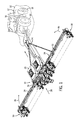
- FIG. 1 is a perspective view of an embodiment of an agricultural implement 10 and a work vehicle 12.
- the illustrated work vehicle 12 has a body 14 that houses an engine, transmission (e.g., gear box), cooling system, and power train.
- the work vehicle 12 has a cabin 16 where an operator may sit or stand to operate the vehicle 12.
- the work vehicle 12 has two front wheels 18 and two rear wheels 20 that rotate to move the work vehicle 12 along the ground 22 at a ground speed.
- the work vehicle 12 may have tracks rather than one or both sets of wheels 18, 20.
- the agricultural implement 10 (e.g., planter) is towed behind the work vehicle 12 across the ground 22, as shown in FIG. 1 .
- the work vehicle 12 supplies a working fluid (e.g., hydraulic fluid) to the agricultural implement via one or more fluid lines 24.
- One or more motors e.g., hydraulic motors
- one or more hydraulic motors may drive a fan and/or seed drive to direct agricultural material (e.g., seeds, fertilizer, etc.) along supply lines 26 from tanks 28 to multiple row units 30 distributed along a frame assembly 32.
- Each row unit 30 may be configured to deposit seeds at a desired depth beneath the soil surface, thereby establishing rows of planted seeds.
- the agricultural implement 10 may have a variety of systems driven by the working fluid (e.g., hydraulic fluid) supplied by the work vehicle 12.
- motors of the agricultural implement may be driven by the working fluid to facilitate delivery of the agricultural product and/or may establish a vacuum pressure within the tanks 28 or supply lines.
- the frame assembly 32 of the agricultural implement 10 may be adjustable to fold into a transport configuration (e.g., via rotation of wings about joints 34) as shown by arrows 36 and/or to pivot and align the frame assembly 32 with a direction of travel 38.
- FIG. 2 is a diagrammatical representation of an embodiment of a hydraulic circuit that may be employed within the work vehicle 12 and the agricultural implement 10.
- the work vehicle 12 includes a hydraulic pump 42, which provides hydraulic fluid flow to the hydraulic components of the agricultural implement 10.
- the work vehicle 12 also includes a hydraulic fluid supply 44, which provides the hydraulic fluid to the hydraulic pump 42.
- the hydraulic pump 42 and the hydraulic fluid supply 44 are fluidly coupled by a fluid line 24.
- the work vehicle 12 provides the hydraulic fluid flow to the agricultural implement 10 via a power beyond valve assembly 40.
- the power beyond valve assembly 40 may be used to control functions on the agricultural implement 10, including seed drives, fan drives, and so forth.
- the hydraulic fluid flows from the work vehicle 12 to the agricultural implement 10 via fluid lines 24 coupled to the power beyond valve assembly 40.
- the power beyond valve assembly 40 facilitates hydraulic coupling of the agricultural implement 10 to the work vehicle 12.
- the hydraulic fluid flows through the power beyond valve assembly 40 to the hydraulic system 46 of the agricultural implement 10.
- the power beyond valve assembly 40 may provide a mechanism that allows the agricultural implement 10 to limit the hydraulic fluid flow and pressure received from the power beyond system of the work vehicle 12. As such, limiting the hydraulic flow and pressure entering the agricultural implement 10 may provide an increase in power in the agricultural implement 10, and it may reduce energy lost through heat generation caused by the inefficiencies of receiving hydraulic fluid flow and pressure beyond an ideal hydraulic fluid flow and pressure for the agricultural implement 10.
- the hydraulic system 46 distributes hydraulic fluid to a hydraulic motor 48 of the agricultural implement 10 via a fluid line 24 at a flow rate sufficient to drive the hydraulic motor 48.
- the hydraulic motor 48 may power at least one function of the agricultural implement 10, such as a seed drive, a fan drive, a vacuum system, and so forth.
- the hydraulic fluid After the hydraulic fluid drives the hydraulic motor 48, the hydraulic fluid returns to the hydraulic system 46 via a fluid line 24. From the hydraulic system 46, the hydraulic fluid may return to the hydraulic fluid supply 44 of the work vehicle 12 through the fluid lines 24 by way of the power beyond valve assembly 40.
- power beyond valve assembly 40 is described herein as being between the work vehicle 12 and the agricultural implement 10, it may be noted that the power beyond valve assembly 40 may be part of the agricultural implement 10, the work vehicle 12, or it may be positioned at any other suitable location between the work vehicle 12 and the agricultural implement 10.
- FIG. 3 is a schematic diagram of an embodiment of the hydraulic system 46.
- the power beyond valve assembly 40 may include a valve block that controls hydraulic fluid flow and pressure to the hydraulic system 46.
- the power beyond valve assembly 40 may be coupled to the agricultural implement 10, the work vehicle 12, or any suitable location between the agricultural implement 10 and the work vehicle 12.
- the hydraulic pump 42 provides the hydraulic fluid flow to the power beyond valve assembly 40 via the fluid line 24.
- a hydraulic line 49 of the power beyond valve assembly 40 receives the hydraulic fluid from the line 24 and directs the hydraulic fluid toward a pressure compensation spool 50.
- the pressure compensation spool 50 may be linearly moveable between an open position and a closed position. In another embodiment, the pressure compensation spool 50 may be rotationally moveable between the open and closed positions. The open position enables hydraulic fluid to flow to the hydraulic system 46. On the other hand, while the pressure compensation spool 50 is in the closed position, the hydraulic fluid flow into the hydraulic system 46 is blocked, thereby enabling excess pressure within the hydraulic system to be discharged through an outlet.
- a pilot line 54 extends from the hydraulic line 53 to a first end of the pressure compensation spool 50.
- Pressure in the pilot line 54 after passing through a flow restrictor 56, urges the pressure compensation spool 50 to move toward the closed position.
- a force associated with the pressure in the pilot line 54 exceeds the combined force of a spring 52 and a force associated with a pressure in a pilot line 60 extending between the hydraulic system 46 outlet and a spring chamber of the pressure compensation spool 50, the pressure compensation spool 50 is driven to the closed position, thereby blocking flow to the hydraulic system 46 inlet.
- the spring 52 provides a force that urges the pressure compensation spool 50 into the open position. Accordingly, the pressure compensation spool 50 may remain in the open position while the force associated with the pressure in the hydraulic line 53 remains below the force contributed by the spring 52 and the force associated with the pressure in the pilot line 60, thereby enabling flow of the hydraulic fluid to the hydraulic system inlet.
- check valves 58 and 59 are configured to limit the hydraulic fluid flow to one direction.
- a first check valve 58 blocks fluid flow from flowing from the hydraulic system 46 inlet to the pressure compensation spool 50, while facilitating flow from the pressure compensation spool 50 to the hydraulic system 46 inlet.
- the second check valve 59 blocks fluid flow from flowing from the spring chamber of the pressure compensation spool 50 to the hydraulic system 46 outlet, while facilitating flow from the hydraulic system 46 outlet to the spring chamber.
- the check valves 58 and 59 may include any suitable check valve configuration to facilitate one-way flow of the hydraulic fluid. As such, the check valves 58 and 59 may be standard ball check valves, spring-loaded ball check valves, diaphragm check valves, and so forth.
- the hydraulic fluid flows through the hydraulic system 46 to the hydraulic motor 48, thereby driving the hydraulic motor 48 in rotation.
- the hydraulic fluid then returns to the hydraulic system 46, and the hydraulic fluid is expelled from the hydraulic system 46 via the outlet.
- the hydraulic fluid flows toward a relief valve 62 via pilot lines 60 and 63.
- the pilot line 63 is in hydraulic communication with the pilot line 60.
- a pressure within the pilot line 63 may be equal to the pressure within the pilot line 60.
- the relief valve 62 is configured to vary the hydraulic fluid pressure within the hydraulic system 46 by controlling pressure within the pilot lines 60 and 63.
- the relief valve 62 may reduce the pressure in the pilot lines 60 and 63 by enabling a substantial portion of the hydraulic fluid to return to the hydraulic fluid supply.
- the relief valve 62 is adjusted toward a closed position, the pressure in the pilot lines 60 and 63 increases, thereby increasing pressure within the hydraulic system.
- the pressure in the pilot lines 60 and 63 urges the pressure compensation spool 50 toward the open position.
- increasing the pressure of the pilot lines 60 and 63 by adjusting the relief valve 62 toward the closed position increases the pressure of the pilot line 54 and the hydraulic line 53 going into the inlet of the hydraulic system 46.
- An increase in the pressure of the pilot line 54 urges the pressure compensation spool 50 into the closed position.
- the relief valve 62 in at least the illustrated embodiment, is controlled manually by an adjustable pressure spring 64.
- a force exerted on the relief valve 62 by the adjustable pressure spring 64 may be controlled by an operator of the work vehicle 12 based on a desired hydraulic pressure within the hydraulic system 46 of the agricultural implement 10.
- the relief valve 62 may open at a higher or lower pressure, thereby controlling the pressure within the pilot lines 60, 63, and 54.
- the pressure relief valve 62 may control hydraulic fluid pressure within the hydraulic motor 48, thereby controlling a rotation speed of the hydraulic motor 48.
- the pressure relief valve 62 opens, the pressure of the hydraulic fluid leaving the hydraulic system 46 may be reduced.
- the pressure in pilot lines 60 and 63 may be reduced.
- the pressure in pilot line 54 may reach a value where its associated force exerted on the pressure compensation spool is greater than the force exerted on the spring side of the pressure compensation spool 50. When this happens, the pressure compensation spool 50 will be urged into the closed position until the pressure in the pilot line 54 is dissipated.
- the pressure relief valve 62 By controlling the pressure in pilot lines 60 and 63, the pressure relief valve 62 also causes the pressure compensation spool 50 to control the flow of the hydraulic fluid entering the power beyond valve assembly 40. Further, when a pressure differential between the hydraulic line 53 and the pilot lines 60 and 63 is created, the hydraulic motor 48 may run more efficiently due to a limited amount of pressure built up in an output of the hydraulic motor 48. The high to low pressure differential of the inlet and the outlet of the hydraulic system 46 allows the hydraulic motor 48 to rotate. For example, the operator of the work vehicle 12 may control the rotations per minute (RPM) of the hydraulic motor 48 of the agricultural implement 10 by adjusting the adjustable pressure spring 64 of the relief valve 62. By way of example, an operator may adjust the adjustable pressure spring 64 to reduce the pressure within the pilot lines 60 and 63.
- RPM rotations per minute
- FIG. 4 shows another system that may be used to adjust the relief valve 62.
- FIG. 4 displays a schematic diagram of an alternative embodiment of a power beyond valve assembly 40 with an actuator controlling the relief valve 62.
- a solenoid 70 is in electrical communication with a controller 72 via a wire 74.
- the solenoid 70 is a proportional actuator.
- the solenoid 70 in a proportional configuration enables the movement of the pressure relief valve 62 proportional to an electric current flowing into the solenoid 70.
- the controller 72 controls the solenoid 70, thereby driving the relief valve 62 to change positions, which enables variable hydraulic fluid flows through the relief valve 62.
- the controller 72 includes a processor 76 and a memory 78.
- the processor 76 may perform instructions stored in the memory 78.
- the instructions may include programs that instruct the solenoid 70 to control the relief valve 62. Additionally, the instructions may be carried out based on an input from a user interface 80.
- the user interface 80 is electrically coupled to the controller 72 via a wire 74.
- the user interface 80 includes a control panel 82, which enables an operator of the work vehicle 12 to input commands to the controller 72.
- the user interface 80 includes a display 84 to display information to the user. Such information that may be displayed to the user could include the hydraulic flow and pressure through the system, the RPM of the hydraulic motor 48, and any other value that may be of use to the user in determining how to control the relief valve 62.
- the input from the user interface 80 may instruct the controller to adjust the position of the relief valve 62.
- the input may be provided by the user of the work vehicle 12 based on RPM specifications of the hydraulic motor 48 of the agricultural implement 10. If the user determines that the RPM of the hydraulic motor 48 is either above or below a desired rate, then the operator may indicate to the controller 72 via the user interface to adjust the relief valve 62 to increase or decrease the RPM of the hydraulic motor 48.
- the solenoid 70 may enable the user of the work vehicle 12 to control the relief valve 62 from the cabin 16 of the work vehicle 12.
- the user may adjust the relief valve 62 from the user interface 80, which may be positioned at any suitable location.
- using the solenoid 70 to control the relief valve 62 may provide greater efficiency in operating the agricultural implement 10, as compared to manually adjusting an adjustable pressure spring 64 on the relief valve 62.
- the illustrated embodiment shows the solenoid 70 controlling the relief valve 62, it may be noted that any type of actuator capable of controlling the relief valve 62 may be used.
- the power beyond valve assembly 40 is represented by a cross-sectional view of an embodiment of a valve block with the pressure compensation spool 50 in the open position.
- the hydraulic flow enters the valve block at the hydraulic line 49 and flows through the hydraulic line 49 in a direction 85. While the pressure compensation spool 50 is in the open position, as illustrated, the hydraulic fluid flows past the pressure compensation spool 50 in a direction 86 and into the hydraulic line 53. The hydraulic fluid then exits the power beyond valve assembly 40 in a direction 87 through the hydraulic line 53 (e.g., toward a hydraulic motor). After the hydraulic fluid passes through the hydraulic system 46, the hydraulic fluid returns to the power beyond valve assembly 40 at the pilot line 60 and flows in a direction 88.
- the hydraulic fluid enters a spring chamber 92 where the fluid provides pressure to act with the spring 52 to urge the pressure compensation spool 50 toward the open position. Subsequently, the hydraulic fluid flows through the spring chamber 92 in directions 89 and 90. Further, the hydraulic fluid flowing in the direction 90 enters the relief valve 62 and exits the power beyond valve assembly 40 toward the hydraulic fluid supply 44 (not shown). Additionally, a force acting on the other side of the pressure compensation spool 50 from the spring chamber 92 is provided by the pressure of the pilot line 54 (not shown). When a differential pressure between the hydraulic line 53 and the pilot line 60 exceeds a determined threshold, the pressure in the pilot line 54 will urge the pressure compensation spool 50 toward the closed position.
- FIG. 6 illustrates a cross-sectional view of the valve block of FIG. 5 with the pressure compensation spool 50 in the closed position after being urged in a direction 102.
- the contact point 96 of the o-ring 94 and the contact point 98 of the valve block are in contact with one another, thereby creating a seal between the contact points 96 and 98.
- the seal blocks the hydraulic fluid flow in the direction 85 from entering the hydraulic line 49.
- the pressure compensation spool 50 blocks the hydraulic fluid flow when the force associated with the pressure in the fluid line 53 exceeds the combined force from the spring 52 and the force associated with the pressure in the pilot lines 60 and 63. Blocking the hydraulic fluid flow from entering the hydraulic motor may limit the flow rate of hydraulic fluid at the hydraulic line 53 until pressure in the hydraulic line 53 is dissipated to a desired level.
- the pressure compensation spool 50 Upon achieving the desired pressure in the pilot lines 60 and 63 set by the relief valve 62, the pressure compensation spool 50 will move in a direction 104 to the open position and allow the flow of hydraulic fluid to resume.
- the pressure compensation spool 50 may re-open based on the decrease in the pressure differential that earlier forced the pressure compensation spool 50 into the closed position.
- FIGS. 5 and 6 the relief valve 62 is shown as a physical embodiment of the schematic diagram illustrated in FIG. 3 .
- FIGS. 4 and 5 are illustrated with the pressure relief valve 62 controllable using the adjustable pressure spring 64.
- the adjustable pressure spring 64 may be replaced in certain embodiments with the solenoid 70 discussed above. Replacing the adjustable pressure spring 64 with the solenoid 70 enables the operator to control the relief valve 62 from the cabin 16 of the work vehicle
Landscapes
- Engineering & Computer Science (AREA)
- General Engineering & Computer Science (AREA)
- Mechanical Engineering (AREA)
- Physics & Mathematics (AREA)
- Fluid Mechanics (AREA)
- Mining & Mineral Resources (AREA)
- Civil Engineering (AREA)
- Structural Engineering (AREA)
- Fluid-Pressure Circuits (AREA)
Abstract
Description
- The invention relates generally to agricultural implements, and more particularly to a power beyond valve assembly for an agricultural implement.
- A wide range of agricultural implements are known, are presently in use, and are particularly designed for towing behind a work vehicle, such as a tractor. In one family of such implements, which includes tillers, planters, and so forth, a wide swath of ground is tilled, planted, or otherwise worked via one or more passes of the implement. The implements may be hydraulically connected to the work vehicle, thereby enabling the work vehicle to drive various components of the implement, such as a hydraulic motor. Hydraulic fluid flow to the components of the implement may be provided by a power beyond system.
- Certain implements may include seed drives, fan drives, and so forth that may be driven by hydraulic fluid. The work vehicle may supply the hydraulic fluid to the hydraulic systems of the implement via the power beyond system to facilitate operation of varying hydraulic functions of the implement. Operators typically set the power beyond system to output the maximum expected hydraulic pressure and fluid flow rate to the hydraulic system of the implement, thereby oversupplying hydraulic fluid when the hydraulic system is operating at a reduced load. Unfortunately, an oversupply of hydraulic fluid and pressure to the hydraulic system may generate excess heat in the work vehicle. Additionally, an oversupply of hydraulic fluid may reduce power available to operate other elements of the implement or the work vehicle.
- A power beyond valve assembly for an agricultural implement, in some embodiments, includes a pressure compensation spool that receives hydraulic fluid from a hydraulic supply and selectively provides the hydraulic fluid to a hydraulic system of the agricultural implement. The position of the pressure compensation spool is adjustable between an open position configured to facilitate flow of the hydraulic fluid to the hydraulic system and a closed position configured to block flow of the hydraulic fluid to the hydraulic system. Additionally, a first fluid connection provides the hydraulic fluid from an inlet of the hydraulic system to a first end of the pressure compensation spool to urge the pressure compensation spool toward the closed position. Further, a second fluid connection provides the hydraulic fluid from an outlet of the hydraulic system to a second end of the pressure compensation spool to urge the pressure compensation spool toward the open position. Furthermore, a pressure relief valve is fluidly coupled to the the outlet of the hydraulic system, and the pressure relief valve is adjustable to vary hydraulic pressure within the hydraulic system and within the second fluid connection.
- In another embodiment, a power beyond valve assembly for an agricultural implement includes a valve block. The valve block includes a housing and a pressure compensation spool disposed within the housing and moveable between an open position and a closed position. Additionally, the pressure compensation spool receives hydraulic fluid from a hydraulic supply, to provide the hydraulic fluid to a hydraulic system of the agricultural implement while the pressure compensation spool is in the open position, and to block the hydraulic fluid to the hydraulic system while the pressure compensation spool is in the closed position. Further, a first fluid connection extending through the housing provides the hydraulic fluid from an inlet of the hydraulic system to a first end of the pressure compensation spool to urge the pressure compensation spool toward the closed position. Furthermore, a second fluid connection extending through the housing provides the hydraulic fluid from an outlet of the hydraulic system to a second end of the pressure compensation spool to urge the pressure compensation spool toward the open position. Moreover, a pressure relief valve disposed within the housing is fluidly coupled to the outlet of the hydraulic system, and the pressure relief value is adjustable to vary hydraulic pressure within the hydraulic system and within the second fluid connection.
- In yet another embodiment, a power beyond valve assembly for an agricultural implement includes a pressure relief valve fluidly coupled to an outlet of a hydraulic system. The pressure relief valve is adjustable to vary hydraulic pressure within the hydraulic system and at the outlet. Additionally, the power beyond valve assembly includes a pressure compensation spool fluidly coupled to an inlet of the hydraulic system. Further, the pressure compensation spool blocks flow of hydraulic fluid to the inlet while the hydraulic pressure at the inlet exceeds the hydraulic pressure at the outlet by a threshold value. Furthermore, the pressure compensation spool facilitates flow of the hydraulic fluid to the inlet.
- These and other features, aspects, and advantages of the present invention will become better understood when the following detailed description is read with reference to the accompanying drawings in which like characters represent like parts throughout the drawings, wherein:
-
FIG. 1 is a perspective view of an embodiment of an agricultural implement coupled to a work vehicle; -
FIG. 2 is a diagrammatical representation of an embodiment of a hydraulic circuit that may be employed within the work vehicle and the agricultural implement ofFIG. 1 ; -
FIG. 3 is a schematic diagram of an embodiment of a power beyond valve assembly that may be employed within the hydraulic circuit ofFIG. 2 ; -
FIG. 4 is a schematic diagram of an alternative embodiment of a power beyond valve assembly, including an actuator to control pressure of hydraulic fluid within a hydraulic system of an agricultural implement; -
FIG. 5 is a cross-sectional view of an embodiment of a valve block including a pressure compensation spool in an open position; and -
FIG. 6 is a cross-sectional view of the valve block ofFIG. 5 with the the pressure compensation spool in a closed position. - One or more specific embodiments will be described below. In an effort to provide a concise description of these embodiments, not all features of an actual implementation are described in the specification. It should be appreciated that in the development of any such actual implementation, as in any engineering or design project, numerous implementation-specific decisions must be made to achieve the developers' specific goals, such as compliance with system-related and business-related constraints, which may vary from one implementation to another. Moreover, it should be appreciated that such a development effort might be complex and time consuming, but would nevertheless be a routine undertaking of design, fabrication, and manufacture for those of ordinary skill having the benefit of this disclosure.
- When introducing elements of various embodiments of the present invention, the articles "a," "an," "the," and "said" are intended to mean that there are one or more of the elements. The terms "comprising," "including," and "having" are intended to be inclusive and mean that there may be additional elements other than the listed elements.
- Embodiments of the power beyond valve assembly described herein may facilitate control of a hydraulic fluid flow between a hydraulic pump in a work vehicle and a hydraulic motor within an agricultural implement. In certain embodiments, the hydraulic pump of the work vehicle directs hydraulic fluid to the hydraulic motor of the implement to drive a hydraulically powered function of the agricultural implement (e.g., a seed drive, a fan drive, a vacuum system, etc.). The hydraulic motor may rotate at a desired speed based on a flow rate and/or a pressure of hydraulic fluid through the motor. In certain embodiments, a pressure compensation spool of the power beyond valve assembly receives the hydraulic fluid from a hydraulic supply and selectively distributes the hydraulic fluid to a hydraulic system of the agricultural implement, which includes the hydraulic motor. Subsequently, the hydraulic motor of the hydraulic system receives the hydraulic fluid, utilizes the energy of the fluid to drive the motor to rotate, and returns the hydraulic fluid to the work vehicle. A pressure within a line that receives the hydraulic fluid from the motor may be controlled via a relief valve. As such, the relief valve enables a user to regulate the pressure of the hydraulic fluid within the hydraulic motor using a pressure compensation spool. When the relief valve relieves pressure at an output of the hydraulic motor, a pressure differential between an input of the hydraulic motor and the output of the hydraulic motor urges the pressure compensation spool to move from an open position to a closed position. While the pressure compensation spool is in the closed position, the hydraulic fluid from the power beyond system stops flowing until the pressure compensation spool moves back to an open position. Control of the hydraulic flow rate and hydraulic pressure increases efficiency of the agricultural implement and the respective hydraulic components by decreasing energy losses (e.g., in the form of heat generation, vibration, etc.) from an oversupply of hydraulic fluid flow. Accordingly, the power beyond valve assembly may reduce the wear on the work vehicle, the agricultural implement, and the respective hydraulic components, and/or increase fuel efficiency of the work vehicle.
- Turning now to the drawings,
FIG. 1 is a perspective view of an embodiment of anagricultural implement 10 and awork vehicle 12. The illustratedwork vehicle 12 has abody 14 that houses an engine, transmission (e.g., gear box), cooling system, and power train. Thework vehicle 12 has acabin 16 where an operator may sit or stand to operate thevehicle 12. Thework vehicle 12 has twofront wheels 18 and tworear wheels 20 that rotate to move thework vehicle 12 along theground 22 at a ground speed. In some embodiments, thework vehicle 12 may have tracks rather than one or both sets ofwheels - The agricultural implement 10 (e.g., planter) is towed behind the
work vehicle 12 across theground 22, as shown inFIG. 1 . Thework vehicle 12 supplies a working fluid (e.g., hydraulic fluid) to the agricultural implement via one ormore fluid lines 24. One or more motors (e.g., hydraulic motors) receive the working fluid from thework vehicle 12 and drive systems of theagricultural implement 10. For example, one or more hydraulic motors may drive a fan and/or seed drive to direct agricultural material (e.g., seeds, fertilizer, etc.) alongsupply lines 26 fromtanks 28 tomultiple row units 30 distributed along aframe assembly 32. Eachrow unit 30 may be configured to deposit seeds at a desired depth beneath the soil surface, thereby establishing rows of planted seeds. - The
agricultural implement 10 may have a variety of systems driven by the working fluid (e.g., hydraulic fluid) supplied by thework vehicle 12. For example, motors of the agricultural implement may be driven by the working fluid to facilitate delivery of the agricultural product and/or may establish a vacuum pressure within thetanks 28 or supply lines. In some embodiments, theframe assembly 32 of the agricultural implement 10 may be adjustable to fold into a transport configuration (e.g., via rotation of wings about joints 34) as shown byarrows 36 and/or to pivot and align theframe assembly 32 with a direction oftravel 38. -
FIG. 2 is a diagrammatical representation of an embodiment of a hydraulic circuit that may be employed within thework vehicle 12 and the agricultural implement 10. In the illustrated embodiment, thework vehicle 12 includes ahydraulic pump 42, which provides hydraulic fluid flow to the hydraulic components of the agricultural implement 10. Additionally, thework vehicle 12 also includes ahydraulic fluid supply 44, which provides the hydraulic fluid to thehydraulic pump 42. Further, thehydraulic pump 42 and thehydraulic fluid supply 44 are fluidly coupled by afluid line 24. - In the illustrated embodiment, the
work vehicle 12 provides the hydraulic fluid flow to the agricultural implement 10 via a power beyondvalve assembly 40. The power beyondvalve assembly 40 may be used to control functions on the agricultural implement 10, including seed drives, fan drives, and so forth. As illustrated, the hydraulic fluid flows from thework vehicle 12 to the agricultural implement 10 viafluid lines 24 coupled to the power beyondvalve assembly 40. The power beyondvalve assembly 40 facilitates hydraulic coupling of the agricultural implement 10 to thework vehicle 12. The hydraulic fluid flows through the power beyondvalve assembly 40 to thehydraulic system 46 of the agricultural implement 10. The power beyondvalve assembly 40 may provide a mechanism that allows the agricultural implement 10 to limit the hydraulic fluid flow and pressure received from the power beyond system of thework vehicle 12. As such, limiting the hydraulic flow and pressure entering the agricultural implement 10 may provide an increase in power in the agricultural implement 10, and it may reduce energy lost through heat generation caused by the inefficiencies of receiving hydraulic fluid flow and pressure beyond an ideal hydraulic fluid flow and pressure for the agricultural implement 10. - Subsequently, the
hydraulic system 46 distributes hydraulic fluid to ahydraulic motor 48 of the agricultural implement 10 via afluid line 24 at a flow rate sufficient to drive thehydraulic motor 48. Thehydraulic motor 48 may power at least one function of the agricultural implement 10, such as a seed drive, a fan drive, a vacuum system, and so forth. After the hydraulic fluid drives thehydraulic motor 48, the hydraulic fluid returns to thehydraulic system 46 via afluid line 24. From thehydraulic system 46, the hydraulic fluid may return to thehydraulic fluid supply 44 of thework vehicle 12 through thefluid lines 24 by way of the power beyondvalve assembly 40. While the power beyondvalve assembly 40 is described herein as being between thework vehicle 12 and the agricultural implement 10, it may be noted that the power beyondvalve assembly 40 may be part of the agricultural implement 10, thework vehicle 12, or it may be positioned at any other suitable location between thework vehicle 12 and the agricultural implement 10. -
FIG. 3 is a schematic diagram of an embodiment of thehydraulic system 46. In certain embodiments, the power beyondvalve assembly 40 may include a valve block that controls hydraulic fluid flow and pressure to thehydraulic system 46. Furthermore, the power beyondvalve assembly 40 may be coupled to the agricultural implement 10, thework vehicle 12, or any suitable location between the agricultural implement 10 and thework vehicle 12. - In the illustrated embodiment, the
hydraulic pump 42 provides the hydraulic fluid flow to the power beyondvalve assembly 40 via thefluid line 24. Ahydraulic line 49 of the power beyondvalve assembly 40 receives the hydraulic fluid from theline 24 and directs the hydraulic fluid toward apressure compensation spool 50. Thepressure compensation spool 50 may be linearly moveable between an open position and a closed position. In another embodiment, thepressure compensation spool 50 may be rotationally moveable between the open and closed positions. The open position enables hydraulic fluid to flow to thehydraulic system 46. On the other hand, while thepressure compensation spool 50 is in the closed position, the hydraulic fluid flow into thehydraulic system 46 is blocked, thereby enabling excess pressure within the hydraulic system to be discharged through an outlet. - Once the hydraulic fluid passes through the
pressure compensation spool 50, the hydraulic fluid flows through ahydraulic line 53 to an inlet of thehydraulic system 46. Apilot line 54 extends from thehydraulic line 53 to a first end of thepressure compensation spool 50. Pressure in thepilot line 54, after passing through aflow restrictor 56, urges thepressure compensation spool 50 to move toward the closed position. As will be discussed in greater detail below, if a force associated with the pressure in thepilot line 54 exceeds the combined force of aspring 52 and a force associated with a pressure in apilot line 60 extending between thehydraulic system 46 outlet and a spring chamber of thepressure compensation spool 50, thepressure compensation spool 50 is driven to the closed position, thereby blocking flow to thehydraulic system 46 inlet. Thespring 52 provides a force that urges thepressure compensation spool 50 into the open position. Accordingly, thepressure compensation spool 50 may remain in the open position while the force associated with the pressure in thehydraulic line 53 remains below the force contributed by thespring 52 and the force associated with the pressure in thepilot line 60, thereby enabling flow of the hydraulic fluid to the hydraulic system inlet. - Further,
check valves first check valve 58 blocks fluid flow from flowing from thehydraulic system 46 inlet to thepressure compensation spool 50, while facilitating flow from thepressure compensation spool 50 to thehydraulic system 46 inlet. Thesecond check valve 59 blocks fluid flow from flowing from the spring chamber of thepressure compensation spool 50 to thehydraulic system 46 outlet, while facilitating flow from thehydraulic system 46 outlet to the spring chamber. Thecheck valves check valves - The hydraulic fluid flows through the
hydraulic system 46 to thehydraulic motor 48, thereby driving thehydraulic motor 48 in rotation. The hydraulic fluid then returns to thehydraulic system 46, and the hydraulic fluid is expelled from thehydraulic system 46 via the outlet. From the outlet of thehydraulic system 46, the hydraulic fluid flows toward arelief valve 62 viapilot lines pilot line 63 is in hydraulic communication with thepilot line 60. As such, a pressure within thepilot line 63 may be equal to the pressure within thepilot line 60. Additionally, therelief valve 62 is configured to vary the hydraulic fluid pressure within thehydraulic system 46 by controlling pressure within thepilot lines relief valve 62 is in a completely open position, the relief valve may reduce the pressure in thepilot lines relief valve 62 is adjusted toward a closed position, the pressure in thepilot lines pilot lines pressure compensation spool 50 toward the open position. As such, increasing the pressure of thepilot lines relief valve 62 toward the closed position increases the pressure of thepilot line 54 and thehydraulic line 53 going into the inlet of thehydraulic system 46. An increase in the pressure of thepilot line 54 urges thepressure compensation spool 50 into the closed position. When thepressure compensation spool 50 is in the closed position, flow of the hydraulic fluid to the hydraulic system is blocked. While the flow of hydraulic fluid is blocked, built up pressure in thehydraulic fluid line 53 is dissipated until the force exerted on thepressure compensation spool 50 by the pressure in thepilot line 54 falls below the force exerted on thepressure compensation spool 50 in the opposite direction by thespring 52 and the force associated with the pressure ofpilot lines pilot line 54 reaches this point, thepressure compensation spool 50 is again urged into the open position. - Furthermore, the
relief valve 62, in at least the illustrated embodiment, is controlled manually by anadjustable pressure spring 64. A force exerted on therelief valve 62 by theadjustable pressure spring 64 may be controlled by an operator of thework vehicle 12 based on a desired hydraulic pressure within thehydraulic system 46 of the agricultural implement 10. By adjusting theadjustable pressure spring 64, therelief valve 62 may open at a higher or lower pressure, thereby controlling the pressure within thepilot lines relief valve 62, afluid line 24 carries the hydraulic fluid back to thehydraulic fluid supply 44 for subsequent use as a hydraulic fluid source for thehydraulic pump 42. - Accordingly, the
pressure relief valve 62 may control hydraulic fluid pressure within thehydraulic motor 48, thereby controlling a rotation speed of thehydraulic motor 48. As thepressure relief valve 62 opens, the pressure of the hydraulic fluid leaving thehydraulic system 46 may be reduced. As such, the pressure inpilot lines pilot lines pressure compensation spool 50. At some point, the pressure inpilot line 54 may reach a value where its associated force exerted on the pressure compensation spool is greater than the force exerted on the spring side of thepressure compensation spool 50. When this happens, thepressure compensation spool 50 will be urged into the closed position until the pressure in thepilot line 54 is dissipated. By controlling the pressure inpilot lines pressure relief valve 62 also causes thepressure compensation spool 50 to control the flow of the hydraulic fluid entering the power beyondvalve assembly 40. Further, when a pressure differential between thehydraulic line 53 and thepilot lines hydraulic motor 48 may run more efficiently due to a limited amount of pressure built up in an output of thehydraulic motor 48. The high to low pressure differential of the inlet and the outlet of thehydraulic system 46 allows thehydraulic motor 48 to rotate. For example, the operator of thework vehicle 12 may control the rotations per minute (RPM) of thehydraulic motor 48 of the agricultural implement 10 by adjusting theadjustable pressure spring 64 of therelief valve 62. By way of example, an operator may adjust theadjustable pressure spring 64 to reduce the pressure within thepilot lines lines hydraulic motor 48. Therefore, thehydraulic motor 48 may operate at a higher RPM. Conversely, when the pressure oflines adjustable pressure spring 64, less power may be available to drive thehydraulic motor 48, and thehydraulic motor 48 may operate at a lower RPM. - As such, the operator of the
work vehicle 12 may manually control the pressure of theadjustable pressure spring 64. For example, an operator may deactivate hydraulic flow to the implement, and manually adjust theadjustable pressure spring 64 at the power beyondvalve assembly 40. However,FIG. 4 shows another system that may be used to adjust therelief valve 62.FIG. 4 displays a schematic diagram of an alternative embodiment of a power beyondvalve assembly 40 with an actuator controlling therelief valve 62. As illustrated, asolenoid 70 is in electrical communication with acontroller 72 via awire 74. Additionally, thesolenoid 70, as illustrated, is a proportional actuator. Thesolenoid 70 in a proportional configuration enables the movement of thepressure relief valve 62 proportional to an electric current flowing into thesolenoid 70. Further, thecontroller 72 controls thesolenoid 70, thereby driving therelief valve 62 to change positions, which enables variable hydraulic fluid flows through therelief valve 62. - In the illustrated embodiment, the
controller 72 includes aprocessor 76 and amemory 78. Theprocessor 76 may perform instructions stored in thememory 78. The instructions may include programs that instruct thesolenoid 70 to control therelief valve 62. Additionally, the instructions may be carried out based on an input from auser interface 80. As illustrated, theuser interface 80 is electrically coupled to thecontroller 72 via awire 74. Further, theuser interface 80 includes acontrol panel 82, which enables an operator of thework vehicle 12 to input commands to thecontroller 72. Theuser interface 80 includes adisplay 84 to display information to the user. Such information that may be displayed to the user could include the hydraulic flow and pressure through the system, the RPM of thehydraulic motor 48, and any other value that may be of use to the user in determining how to control therelief valve 62. - Further, the input from the
user interface 80 may instruct the controller to adjust the position of therelief valve 62. The input may be provided by the user of thework vehicle 12 based on RPM specifications of thehydraulic motor 48 of the agricultural implement 10. If the user determines that the RPM of thehydraulic motor 48 is either above or below a desired rate, then the operator may indicate to thecontroller 72 via the user interface to adjust therelief valve 62 to increase or decrease the RPM of thehydraulic motor 48. Furthermore, thesolenoid 70 may enable the user of thework vehicle 12 to control therelief valve 62 from thecabin 16 of thework vehicle 12. For example, instead of the user of thework vehicle 12 manually adjusting therelief valve 62 at the location of the power beyondvalve assembly 40, the user may adjust therelief valve 62 from theuser interface 80, which may be positioned at any suitable location. As such, using thesolenoid 70 to control therelief valve 62 may provide greater efficiency in operating the agricultural implement 10, as compared to manually adjusting anadjustable pressure spring 64 on therelief valve 62. Further, while the illustrated embodiment shows thesolenoid 70 controlling therelief valve 62, it may be noted that any type of actuator capable of controlling therelief valve 62 may be used. - Turning now to
FIG. 5 , the power beyondvalve assembly 40 is represented by a cross-sectional view of an embodiment of a valve block with thepressure compensation spool 50 in the open position. In the illustrated embodiment, the hydraulic flow enters the valve block at thehydraulic line 49 and flows through thehydraulic line 49 in adirection 85. While thepressure compensation spool 50 is in the open position, as illustrated, the hydraulic fluid flows past thepressure compensation spool 50 in adirection 86 and into thehydraulic line 53. The hydraulic fluid then exits the power beyondvalve assembly 40 in adirection 87 through the hydraulic line 53 (e.g., toward a hydraulic motor). After the hydraulic fluid passes through thehydraulic system 46, the hydraulic fluid returns to the power beyondvalve assembly 40 at thepilot line 60 and flows in adirection 88. Subsequently, the hydraulic fluid enters aspring chamber 92 where the fluid provides pressure to act with thespring 52 to urge thepressure compensation spool 50 toward the open position. Subsequently, the hydraulic fluid flows through thespring chamber 92 indirections direction 90 enters therelief valve 62 and exits the power beyondvalve assembly 40 toward the hydraulic fluid supply 44 (not shown). Additionally, a force acting on the other side of thepressure compensation spool 50 from thespring chamber 92 is provided by the pressure of the pilot line 54 (not shown). When a differential pressure between thehydraulic line 53 and thepilot line 60 exceeds a determined threshold, the pressure in thepilot line 54 will urge thepressure compensation spool 50 toward the closed position. - Moreover, a
notch 94 is illustrated in thepressure compensation spool 50. Thenotch 94 allows the flow of the hydraulic fluid to gradually increase or decrease as thepressure compensation spool 50 moves between the open position and the closed position. Further, when thepressure compensation spool 50 is in the closed position, a seal between acontact point 96 on thepressure compensation spool 50 and acontact point 98 on the valve block of the power beyondvalve assembly 40 blocks the flow of hydraulic fluid towardhydraulic line 53.FIG. 6 illustrates a cross-sectional view of the valve block ofFIG. 5 with thepressure compensation spool 50 in the closed position after being urged in adirection 102. With the pressure compensation spool in the closed position, thecontact point 96 of the o-ring 94 and thecontact point 98 of the valve block are in contact with one another, thereby creating a seal between the contact points 96 and 98. The seal blocks the hydraulic fluid flow in thedirection 85 from entering thehydraulic line 49. As discussed above, thepressure compensation spool 50 blocks the hydraulic fluid flow when the force associated with the pressure in thefluid line 53 exceeds the combined force from thespring 52 and the force associated with the pressure in thepilot lines hydraulic line 53 until pressure in thehydraulic line 53 is dissipated to a desired level. Upon achieving the desired pressure in thepilot lines relief valve 62, thepressure compensation spool 50 will move in adirection 104 to the open position and allow the flow of hydraulic fluid to resume. Thepressure compensation spool 50 may re-open based on the decrease in the pressure differential that earlier forced thepressure compensation spool 50 into the closed position. - Further, in both
FIGS. 5 and6 , therelief valve 62 is shown as a physical embodiment of the schematic diagram illustrated inFIG. 3 . As such,FIGS. 4 and5 are illustrated with thepressure relief valve 62 controllable using theadjustable pressure spring 64. It may be noted that theadjustable pressure spring 64 may be replaced in certain embodiments with thesolenoid 70 discussed above. Replacing theadjustable pressure spring 64 with thesolenoid 70 enables the operator to control therelief valve 62 from thecabin 16 of the work vehicle - While only certain features of the invention have been illustrated and described herein, many modifications and changes will occur to those skilled in the art. It is, therefore, to be understood that the appended claims are intended to cover all such modifications and changes as fall within the true spirit of the invention.
Claims (8)
- A power beyond valve assembly (40) for an agricultural implement (10), comprising:- a pressure compensation spool (50) configured to receive hydraulic fluid from a hydraulic supply (44) and to selectively provide the hydraulic fluid to a hydraulic system (46) of the agricultural implement, wherein a position of the pressure compensation spool (50) is adjustable between an open position configured to facilitate flow of the hydraulic fluid to the hydraulic system (46) and a closed position configured to block flow of the hydraulic fluid to the hydraulic system (46);- a first fluid connection configured to provide the hydraulic fluid from an inlet of the hydraulic system (46) to a first end of the pressure compensation spool (50) to urge the pressure compensation spool (50) toward the closed position;- a second fluid connection configured to provide the hydraulic fluid from an outlet of the hydraulic system (46) to a second end of the pressure compensation spool (50) to urge the pressure compensation spool (50) toward the open position; and- a pressure relief valve (62) fluidly coupled to the outlet of the hydraulic system (46), wherein the pressure relief value (62) is adjustable to vary hydraulic pressure within the hydraulic system (46) and within the second fluid connection.
- The power beyond valve assembly (40) of claim 1, wherein the pressure relief valve (62) is manually adjustable.
- The power beyond valve assembly (40) of claim 1, wherein the pressure relief valve (62) comprises an actuator (70) configured to adjust the pressure relief valve (62).
- The power beyond valve assembly (40) of claim 3, wherein the actuator (70) is configured to adjust the pressure relief valve (62) to establish at least three different hydraulic pressures within the second fluid connection.
- The power beyond valve assembly (40) of claim 3, comprising a controller (72) communicatively coupled to the actuator (70), wherein the actuator (70) is controllable via a set of instructions stored in a memory of the controller (78), and the set of instructions is executed by a processor of the controller (76) and transmitted to the actuator (70).
- The power beyond valve assembly (40) of claim 5, comprising a user interface (80) communicatively coupled to the controller (72) and configured to receive an operator input to control the pressure relief valve (62).
- The power beyond valve assembly (40) of claim 6, wherein the user interface is controllable from a cabin (16) of a work vehicle.
- The power beyond valve assembly (40) of claim 1, wherein the pressure relief valve (62) is adjustable to maintain a desired rotations per minute (RPM) of a hydraulic motor of the hydraulic system.
Applications Claiming Priority (1)
| Application Number | Priority Date | Filing Date | Title |
|---|---|---|---|
| US14/106,232 US20150167276A1 (en) | 2013-12-13 | 2013-12-13 | Power beyond valve assembly for an agricultural implement |
Publications (2)
| Publication Number | Publication Date |
|---|---|
| EP2886877A1 true EP2886877A1 (en) | 2015-06-24 |
| EP2886877B1 EP2886877B1 (en) | 2018-01-03 |
Family
ID=52021080
Family Applications (1)
| Application Number | Title | Priority Date | Filing Date |
|---|---|---|---|
| EP14197255.4A Active EP2886877B1 (en) | 2013-12-13 | 2014-12-10 | Power beyond valve assembly for an agricultural implement |
Country Status (2)
| Country | Link |
|---|---|
| US (1) | US20150167276A1 (en) |
| EP (1) | EP2886877B1 (en) |
Cited By (1)
| Publication number | Priority date | Publication date | Assignee | Title |
|---|---|---|---|---|
| WO2020114909A1 (en) * | 2018-12-03 | 2020-06-11 | Komatsu Germany Gmbh | Tool for adjusting high-pressure hydraulic circuits on hydraulic excavators |
Families Citing this family (6)
| Publication number | Priority date | Publication date | Assignee | Title |
|---|---|---|---|---|
| WO2017071753A1 (en) * | 2015-10-29 | 2017-05-04 | Festo Ag & Co. Kg | Fluid control device and method for operating a fluid control device |
| US10227998B2 (en) | 2015-12-31 | 2019-03-12 | Cnh Industrial America Llc | System for controlling the supply of hydraulic fluid to a work vehicle implement |
| JP2017133596A (en) * | 2016-01-28 | 2017-08-03 | Kyb株式会社 | Pilot type switching valve |
| US10104826B2 (en) | 2016-01-29 | 2018-10-23 | Cnh Industrial America Llc | System for controlling the supply of hydraulic fluid to a work vehicle implement |
| US10820491B2 (en) * | 2018-08-09 | 2020-11-03 | Cnh Industrial Canada, Ltd. | System and method for initiating control of components of a work vehicle based on input received from a user interface of an associated agricultural implement |
| JP7207279B2 (en) * | 2019-11-27 | 2023-01-18 | トヨタ自動車株式会社 | Mold for resin impregnation molding |
Citations (2)
| Publication number | Priority date | Publication date | Assignee | Title |
|---|---|---|---|---|
| DE102004033316A1 (en) * | 2004-07-09 | 2006-02-09 | Bosch Rexroth Aktiengesellschaft | Method for controlling a Hubwerksventilanordnung |
| US20110139260A1 (en) * | 2009-12-10 | 2011-06-16 | Hydraforce, Inc. | Proportional Motion Control Valve |
Family Cites Families (11)
| Publication number | Priority date | Publication date | Assignee | Title |
|---|---|---|---|---|
| FR2186610B1 (en) * | 1972-05-23 | 1975-08-29 | Verlinde Sa | |
| US4020867A (en) * | 1974-08-26 | 1977-05-03 | Nisshin Sangyo Kabushiki Kaisha | Multiple pressure compensated flow control valve device of parallel connection used with fixed displacement pump |
| US4481770A (en) * | 1982-03-22 | 1984-11-13 | Caterpillar Tractor Co. | Fluid system with flow compensated torque control |
| US4703612A (en) * | 1986-09-24 | 1987-11-03 | New Holland Inc. | Hydraulic system for unitized raking implement |
| IT1208866B (en) * | 1987-04-14 | 1989-07-10 | Chs Vickers Spa | HYDRAULIC CONTROL CIRCUIT FOR EARTH-MOVING MACHINE WORKING BODIES WITH ABOVE MENTION CIRCUIT |
| US5101629A (en) * | 1989-02-20 | 1992-04-07 | Hitachi Construction Machinery Co., Ltd. | Hydraulic circuit system for working machine |
| JP3654599B2 (en) * | 1994-09-09 | 2005-06-02 | 株式会社小松製作所 | Transmission device for hydraulic drive device and transmission control method therefor |
| DE4443462A1 (en) * | 1994-12-07 | 1996-06-13 | Danfoss As | Additional device for a hydraulic control device |
| JPH09317879A (en) * | 1996-05-27 | 1997-12-12 | Komatsu Ltd | Back pressure control circuit for hydraulic drive |
| US20140069091A1 (en) * | 2011-03-17 | 2014-03-13 | Parker Hannifin Corporation | Electro-hydraulic system for controlling multiple functions |
| US8899143B2 (en) * | 2011-06-28 | 2014-12-02 | Caterpillar Inc. | Hydraulic control system having variable pressure relief |
-
2013
- 2013-12-13 US US14/106,232 patent/US20150167276A1/en not_active Abandoned
-
2014
- 2014-12-10 EP EP14197255.4A patent/EP2886877B1/en active Active
Patent Citations (2)
| Publication number | Priority date | Publication date | Assignee | Title |
|---|---|---|---|---|
| DE102004033316A1 (en) * | 2004-07-09 | 2006-02-09 | Bosch Rexroth Aktiengesellschaft | Method for controlling a Hubwerksventilanordnung |
| US20110139260A1 (en) * | 2009-12-10 | 2011-06-16 | Hydraforce, Inc. | Proportional Motion Control Valve |
Cited By (1)
| Publication number | Priority date | Publication date | Assignee | Title |
|---|---|---|---|---|
| WO2020114909A1 (en) * | 2018-12-03 | 2020-06-11 | Komatsu Germany Gmbh | Tool for adjusting high-pressure hydraulic circuits on hydraulic excavators |
Also Published As
| Publication number | Publication date |
|---|---|
| EP2886877B1 (en) | 2018-01-03 |
| BR102014031393A2 (en) | 2017-05-09 |
| US20150167276A1 (en) | 2015-06-18 |
Similar Documents
| Publication | Publication Date | Title |
|---|---|---|
| EP2886877B1 (en) | Power beyond valve assembly for an agricultural implement | |
| CA2858493C (en) | Pressure control system and method for an agricultural planter | |
| CN106930990B (en) | System for controlling the supply of hydraulic fluid to a work vehicle implement | |
| EP2889492B1 (en) | Fluid cooler bypass system for an agricultural work vehicle | |
| US10104826B2 (en) | System for controlling the supply of hydraulic fluid to a work vehicle implement | |
| US20040244659A1 (en) | Variable rate meter drive system | |
| US11713775B2 (en) | Agricultural implements and hydraulic circuits therefor incorporating one or more priority valves | |
| EP2712502B1 (en) | Trailed agricultural implement pump with hydraulic flow rate control | |
| US8297209B2 (en) | Electropneumatic installation applied to seeders having independent units associated to pneumatic seed dosing devices | |
| US10912245B2 (en) | System and method for regulating the flow of fluid supplied to actuators of an agricultural implement | |
| US10820471B2 (en) | Hydraulic system for an agricultural implement incorporating an implement-based override valve | |
| US20200060063A1 (en) | Hydraulic system for an agricultural implement incorporating implement-based hydraulic load sensing | |
| EP2686560B1 (en) | Auxiliary drive for working implements | |
| EP4170189A1 (en) | System and method for controlling hydraulic pump operation within a work vehicle | |
| EP4063668B1 (en) | System to reduce line loss in pressure control hydraulic circuit | |
| CA2538534C (en) | Modular planter hydraulic system and method | |
| BR102014031393B1 (en) | ASSEMBLY OF AN EXCESS FORCE VALVE FOR AN AGRICULTURAL IMPLEMENT | |
| US6997098B2 (en) | Method and apparatus for driving hydraulic motors with agricultural tractors | |
| KR20200004127A (en) | Agricultural Vehicle | |
| KR102095855B1 (en) | Tractor attaching type working machinery for supplying agricultural water | |
| BR202015029711U2 (en) | multifunctional hydraulic planter unit | |
| BR202018001619U2 (en) | hydraulic unit with electronic control for height adjustment on planters |
Legal Events
| Date | Code | Title | Description |
|---|---|---|---|
| PUAI | Public reference made under article 153(3) epc to a published international application that has entered the european phase |
Free format text: ORIGINAL CODE: 0009012 |
|
| 17P | Request for examination filed |
Effective date: 20141210 |
|
| AK | Designated contracting states |
Kind code of ref document: A1 Designated state(s): AL AT BE BG CH CY CZ DE DK EE ES FI FR GB GR HR HU IE IS IT LI LT LU LV MC MK MT NL NO PL PT RO RS SE SI SK SM TR |
|
| AX | Request for extension of the european patent |
Extension state: BA ME |
|
| RIN1 | Information on inventor provided before grant (corrected) |
Inventor name: BRINKLEY, JERRY L. Inventor name: RESTAINO, III, GERARD Inventor name: STOEVER, GUY T. |
|
| R17P | Request for examination filed (corrected) |
Effective date: 20160104 |
|
| RBV | Designated contracting states (corrected) |
Designated state(s): AL AT BE BG CH CY CZ DE DK EE ES FI FR GB GR HR HU IE IS IT LI LT LU LV MC MK MT NL NO PL PT RO RS SE SI SK SM TR |
|
| RIC1 | Information provided on ipc code assigned before grant |
Ipc: F15B 11/028 20060101AFI20170601BHEP |
|
| GRAP | Despatch of communication of intention to grant a patent |
Free format text: ORIGINAL CODE: EPIDOSNIGR1 |
|
| STAA | Information on the status of an ep patent application or granted ep patent |
Free format text: STATUS: GRANT OF PATENT IS INTENDED |
|
| INTG | Intention to grant announced |
Effective date: 20170725 |
|
| GRAS | Grant fee paid |
Free format text: ORIGINAL CODE: EPIDOSNIGR3 |
|
| GRAA | (expected) grant |
Free format text: ORIGINAL CODE: 0009210 |
|
| STAA | Information on the status of an ep patent application or granted ep patent |
Free format text: STATUS: THE PATENT HAS BEEN GRANTED |
|
| AK | Designated contracting states |
Kind code of ref document: B1 Designated state(s): AL AT BE BG CH CY CZ DE DK EE ES FI FR GB GR HR HU IE IS IT LI LT LU LV MC MK MT NL NO PL PT RO RS SE SI SK SM TR |
|
| REG | Reference to a national code |
Ref country code: GB Ref legal event code: FG4D |
|
| REG | Reference to a national code |
Ref country code: CH Ref legal event code: EP Ref country code: AT Ref legal event code: REF Ref document number: 960555 Country of ref document: AT Kind code of ref document: T Effective date: 20180115 |
|
| REG | Reference to a national code |
Ref country code: IE Ref legal event code: FG4D |
|
| REG | Reference to a national code |
Ref country code: DE Ref legal event code: R096 Ref document number: 602014019335 Country of ref document: DE |
|
| REG | Reference to a national code |
Ref country code: NL Ref legal event code: MP Effective date: 20180103 |
|
| REG | Reference to a national code |
Ref country code: LT Ref legal event code: MG4D |
|
| REG | Reference to a national code |
Ref country code: AT Ref legal event code: MK05 Ref document number: 960555 Country of ref document: AT Kind code of ref document: T Effective date: 20180103 |
|
| PG25 | Lapsed in a contracting state [announced via postgrant information from national office to epo] |
Ref country code: NL Free format text: LAPSE BECAUSE OF FAILURE TO SUBMIT A TRANSLATION OF THE DESCRIPTION OR TO PAY THE FEE WITHIN THE PRESCRIBED TIME-LIMIT Effective date: 20180103 |
|
| PG25 | Lapsed in a contracting state [announced via postgrant information from national office to epo] |
Ref country code: NO Free format text: LAPSE BECAUSE OF FAILURE TO SUBMIT A TRANSLATION OF THE DESCRIPTION OR TO PAY THE FEE WITHIN THE PRESCRIBED TIME-LIMIT Effective date: 20180403 Ref country code: FI Free format text: LAPSE BECAUSE OF FAILURE TO SUBMIT A TRANSLATION OF THE DESCRIPTION OR TO PAY THE FEE WITHIN THE PRESCRIBED TIME-LIMIT Effective date: 20180103 Ref country code: LT Free format text: LAPSE BECAUSE OF FAILURE TO SUBMIT A TRANSLATION OF THE DESCRIPTION OR TO PAY THE FEE WITHIN THE PRESCRIBED TIME-LIMIT Effective date: 20180103 Ref country code: HR Free format text: LAPSE BECAUSE OF FAILURE TO SUBMIT A TRANSLATION OF THE DESCRIPTION OR TO PAY THE FEE WITHIN THE PRESCRIBED TIME-LIMIT Effective date: 20180103 Ref country code: ES Free format text: LAPSE BECAUSE OF FAILURE TO SUBMIT A TRANSLATION OF THE DESCRIPTION OR TO PAY THE FEE WITHIN THE PRESCRIBED TIME-LIMIT Effective date: 20180103 Ref country code: CY Free format text: LAPSE BECAUSE OF FAILURE TO SUBMIT A TRANSLATION OF THE DESCRIPTION OR TO PAY THE FEE WITHIN THE PRESCRIBED TIME-LIMIT Effective date: 20180103 |
|
| PG25 | Lapsed in a contracting state [announced via postgrant information from national office to epo] |
Ref country code: GR Free format text: LAPSE BECAUSE OF FAILURE TO SUBMIT A TRANSLATION OF THE DESCRIPTION OR TO PAY THE FEE WITHIN THE PRESCRIBED TIME-LIMIT Effective date: 20180404 Ref country code: BG Free format text: LAPSE BECAUSE OF FAILURE TO SUBMIT A TRANSLATION OF THE DESCRIPTION OR TO PAY THE FEE WITHIN THE PRESCRIBED TIME-LIMIT Effective date: 20180403 Ref country code: IS Free format text: LAPSE BECAUSE OF FAILURE TO SUBMIT A TRANSLATION OF THE DESCRIPTION OR TO PAY THE FEE WITHIN THE PRESCRIBED TIME-LIMIT Effective date: 20180503 Ref country code: PL Free format text: LAPSE BECAUSE OF FAILURE TO SUBMIT A TRANSLATION OF THE DESCRIPTION OR TO PAY THE FEE WITHIN THE PRESCRIBED TIME-LIMIT Effective date: 20180103 Ref country code: SE Free format text: LAPSE BECAUSE OF FAILURE TO SUBMIT A TRANSLATION OF THE DESCRIPTION OR TO PAY THE FEE WITHIN THE PRESCRIBED TIME-LIMIT Effective date: 20180103 Ref country code: LV Free format text: LAPSE BECAUSE OF FAILURE TO SUBMIT A TRANSLATION OF THE DESCRIPTION OR TO PAY THE FEE WITHIN THE PRESCRIBED TIME-LIMIT Effective date: 20180103 Ref country code: RS Free format text: LAPSE BECAUSE OF FAILURE TO SUBMIT A TRANSLATION OF THE DESCRIPTION OR TO PAY THE FEE WITHIN THE PRESCRIBED TIME-LIMIT Effective date: 20180103 Ref country code: AT Free format text: LAPSE BECAUSE OF FAILURE TO SUBMIT A TRANSLATION OF THE DESCRIPTION OR TO PAY THE FEE WITHIN THE PRESCRIBED TIME-LIMIT Effective date: 20180103 |
|
| REG | Reference to a national code |
Ref country code: DE Ref legal event code: R097 Ref document number: 602014019335 Country of ref document: DE |
|
| REG | Reference to a national code |
Ref country code: FR Ref legal event code: PLFP Year of fee payment: 5 |
|
| PG25 | Lapsed in a contracting state [announced via postgrant information from national office to epo] |
Ref country code: EE Free format text: LAPSE BECAUSE OF FAILURE TO SUBMIT A TRANSLATION OF THE DESCRIPTION OR TO PAY THE FEE WITHIN THE PRESCRIBED TIME-LIMIT Effective date: 20180103 Ref country code: AL Free format text: LAPSE BECAUSE OF FAILURE TO SUBMIT A TRANSLATION OF THE DESCRIPTION OR TO PAY THE FEE WITHIN THE PRESCRIBED TIME-LIMIT Effective date: 20180103 Ref country code: RO Free format text: LAPSE BECAUSE OF FAILURE TO SUBMIT A TRANSLATION OF THE DESCRIPTION OR TO PAY THE FEE WITHIN THE PRESCRIBED TIME-LIMIT Effective date: 20180103 |
|
| PLBE | No opposition filed within time limit |
Free format text: ORIGINAL CODE: 0009261 |
|
| STAA | Information on the status of an ep patent application or granted ep patent |
Free format text: STATUS: NO OPPOSITION FILED WITHIN TIME LIMIT |
|
| PG25 | Lapsed in a contracting state [announced via postgrant information from national office to epo] |
Ref country code: CZ Free format text: LAPSE BECAUSE OF FAILURE TO SUBMIT A TRANSLATION OF THE DESCRIPTION OR TO PAY THE FEE WITHIN THE PRESCRIBED TIME-LIMIT Effective date: 20180103 Ref country code: SM Free format text: LAPSE BECAUSE OF FAILURE TO SUBMIT A TRANSLATION OF THE DESCRIPTION OR TO PAY THE FEE WITHIN THE PRESCRIBED TIME-LIMIT Effective date: 20180103 Ref country code: DK Free format text: LAPSE BECAUSE OF FAILURE TO SUBMIT A TRANSLATION OF THE DESCRIPTION OR TO PAY THE FEE WITHIN THE PRESCRIBED TIME-LIMIT Effective date: 20180103 Ref country code: SK Free format text: LAPSE BECAUSE OF FAILURE TO SUBMIT A TRANSLATION OF THE DESCRIPTION OR TO PAY THE FEE WITHIN THE PRESCRIBED TIME-LIMIT Effective date: 20180103 |
|
| 26N | No opposition filed |
Effective date: 20181005 |
|
| PG25 | Lapsed in a contracting state [announced via postgrant information from national office to epo] |
Ref country code: SI Free format text: LAPSE BECAUSE OF FAILURE TO SUBMIT A TRANSLATION OF THE DESCRIPTION OR TO PAY THE FEE WITHIN THE PRESCRIBED TIME-LIMIT Effective date: 20180103 |
|
| REG | Reference to a national code |
Ref country code: CH Ref legal event code: PL |
|
| PG25 | Lapsed in a contracting state [announced via postgrant information from national office to epo] |
Ref country code: MC Free format text: LAPSE BECAUSE OF FAILURE TO SUBMIT A TRANSLATION OF THE DESCRIPTION OR TO PAY THE FEE WITHIN THE PRESCRIBED TIME-LIMIT Effective date: 20180103 Ref country code: LU Free format text: LAPSE BECAUSE OF NON-PAYMENT OF DUE FEES Effective date: 20181210 |
|
| REG | Reference to a national code |
Ref country code: IE Ref legal event code: MM4A |
|
| REG | Reference to a national code |
Ref country code: BE Ref legal event code: MM Effective date: 20181231 |
|
| PG25 | Lapsed in a contracting state [announced via postgrant information from national office to epo] |
Ref country code: IE Free format text: LAPSE BECAUSE OF NON-PAYMENT OF DUE FEES Effective date: 20181210 |
|
| PG25 | Lapsed in a contracting state [announced via postgrant information from national office to epo] |
Ref country code: BE Free format text: LAPSE BECAUSE OF NON-PAYMENT OF DUE FEES Effective date: 20181231 |
|
| PG25 | Lapsed in a contracting state [announced via postgrant information from national office to epo] |
Ref country code: CH Free format text: LAPSE BECAUSE OF NON-PAYMENT OF DUE FEES Effective date: 20181231 Ref country code: LI Free format text: LAPSE BECAUSE OF NON-PAYMENT OF DUE FEES Effective date: 20181231 |
|
| PG25 | Lapsed in a contracting state [announced via postgrant information from national office to epo] |
Ref country code: MT Free format text: LAPSE BECAUSE OF NON-PAYMENT OF DUE FEES Effective date: 20181210 |
|
| PG25 | Lapsed in a contracting state [announced via postgrant information from national office to epo] |
Ref country code: TR Free format text: LAPSE BECAUSE OF FAILURE TO SUBMIT A TRANSLATION OF THE DESCRIPTION OR TO PAY THE FEE WITHIN THE PRESCRIBED TIME-LIMIT Effective date: 20180103 |
|
| PG25 | Lapsed in a contracting state [announced via postgrant information from national office to epo] |
Ref country code: PT Free format text: LAPSE BECAUSE OF FAILURE TO SUBMIT A TRANSLATION OF THE DESCRIPTION OR TO PAY THE FEE WITHIN THE PRESCRIBED TIME-LIMIT Effective date: 20180103 |
|
| PG25 | Lapsed in a contracting state [announced via postgrant information from national office to epo] |
Ref country code: MK Free format text: LAPSE BECAUSE OF NON-PAYMENT OF DUE FEES Effective date: 20180103 Ref country code: HU Free format text: LAPSE BECAUSE OF FAILURE TO SUBMIT A TRANSLATION OF THE DESCRIPTION OR TO PAY THE FEE WITHIN THE PRESCRIBED TIME-LIMIT; INVALID AB INITIO Effective date: 20141210 |
|
| PGFP | Annual fee paid to national office [announced via postgrant information from national office to epo] |
Ref country code: FR Payment date: 20231220 Year of fee payment: 10 |
|
| PG25 | Lapsed in a contracting state [announced via postgrant information from national office to epo] |
Ref country code: FR Free format text: LAPSE BECAUSE OF NON-PAYMENT OF DUE FEES Effective date: 20241231 |
|
| PGFP | Annual fee paid to national office [announced via postgrant information from national office to epo] |
Ref country code: GB Payment date: 20251223 Year of fee payment: 12 |
|
| PGFP | Annual fee paid to national office [announced via postgrant information from national office to epo] |
Ref country code: IT Payment date: 20251218 Year of fee payment: 12 |
|
| PGFP | Annual fee paid to national office [announced via postgrant information from national office to epo] |
Ref country code: DE Payment date: 20251229 Year of fee payment: 12 |