EP2886813B1 - Deactivating tappet - Google Patents
Deactivating tappet Download PDFInfo
- Publication number
- EP2886813B1 EP2886813B1 EP14198338.7A EP14198338A EP2886813B1 EP 2886813 B1 EP2886813 B1 EP 2886813B1 EP 14198338 A EP14198338 A EP 14198338A EP 2886813 B1 EP2886813 B1 EP 2886813B1
- Authority
- EP
- European Patent Office
- Prior art keywords
- tappet
- deactivating
- main body
- housing
- shoulder
- Prior art date
- Legal status (The legal status is an assumption and is not a legal conclusion. Google has not performed a legal analysis and makes no representation as to the accuracy of the status listed.)
- Active
Links
Images
Classifications
-
- F—MECHANICAL ENGINEERING; LIGHTING; HEATING; WEAPONS; BLASTING
- F01—MACHINES OR ENGINES IN GENERAL; ENGINE PLANTS IN GENERAL; STEAM ENGINES
- F01L—CYCLICALLY OPERATING VALVES FOR MACHINES OR ENGINES
- F01L13/00—Modifications of valve-gear to facilitate reversing, braking, starting, changing compression ratio, or other specific operations
- F01L13/0005—Deactivating valves
-
- F—MECHANICAL ENGINEERING; LIGHTING; HEATING; WEAPONS; BLASTING
- F01—MACHINES OR ENGINES IN GENERAL; ENGINE PLANTS IN GENERAL; STEAM ENGINES
- F01L—CYCLICALLY OPERATING VALVES FOR MACHINES OR ENGINES
- F01L1/00—Valve-gear or valve arrangements, e.g. lift-valve gear
- F01L1/20—Adjusting or compensating clearance
- F01L1/22—Adjusting or compensating clearance automatically, e.g. mechanically
- F01L1/24—Adjusting or compensating clearance automatically, e.g. mechanically by fluid means, e.g. hydraulically
- F01L1/2405—Adjusting or compensating clearance automatically, e.g. mechanically by fluid means, e.g. hydraulically by means of a hydraulic adjusting device located between the cylinder head and rocker arm
-
- F—MECHANICAL ENGINEERING; LIGHTING; HEATING; WEAPONS; BLASTING
- F01—MACHINES OR ENGINES IN GENERAL; ENGINE PLANTS IN GENERAL; STEAM ENGINES
- F01L—CYCLICALLY OPERATING VALVES FOR MACHINES OR ENGINES
- F01L1/00—Valve-gear or valve arrangements, e.g. lift-valve gear
- F01L1/20—Adjusting or compensating clearance
- F01L1/22—Adjusting or compensating clearance automatically, e.g. mechanically
- F01L1/24—Adjusting or compensating clearance automatically, e.g. mechanically by fluid means, e.g. hydraulically
- F01L1/245—Hydraulic tappets
-
- F—MECHANICAL ENGINEERING; LIGHTING; HEATING; WEAPONS; BLASTING
- F01—MACHINES OR ENGINES IN GENERAL; ENGINE PLANTS IN GENERAL; STEAM ENGINES
- F01L—CYCLICALLY OPERATING VALVES FOR MACHINES OR ENGINES
- F01L13/00—Modifications of valve-gear to facilitate reversing, braking, starting, changing compression ratio, or other specific operations
- F01L13/0005—Deactivating valves
- F01L2013/001—Deactivating cylinders
-
- Y—GENERAL TAGGING OF NEW TECHNOLOGICAL DEVELOPMENTS; GENERAL TAGGING OF CROSS-SECTIONAL TECHNOLOGIES SPANNING OVER SEVERAL SECTIONS OF THE IPC; TECHNICAL SUBJECTS COVERED BY FORMER USPC CROSS-REFERENCE ART COLLECTIONS [XRACs] AND DIGESTS
- Y10—TECHNICAL SUBJECTS COVERED BY FORMER USPC
- Y10T—TECHNICAL SUBJECTS COVERED BY FORMER US CLASSIFICATION
- Y10T74/00—Machine element or mechanism
- Y10T74/21—Elements
- Y10T74/2101—Cams
- Y10T74/2107—Follower
Definitions
- the invention relates to a deactivating tappet, for example for use in a valve train in a combustion engine, according to the preamble of claim 1. More specific, the invention relates to deactivating hydraulic lash adjusters. Such a deactivating tappet is known from US 20060225684 .
- Deactivating hydraulic lash adjusters are used in combustion engines to be able to turn cylinders on or off depending on the power demanded from the engine.
- the motor management system of such an engine decides whether all cylinders are required for providing the desired power, or that some of the cylinders can be deactivated. This deactivating is achieved by reducing or disabling the movement of the respective valves.
- US 2011061615 discloses a deactivating hydraulic lash adjuster.
- This prior art hydraulic lash adjuster or tappet has a housing with a body slidably arranged in the housing. Springs are provided to urge the body into a rest position and locking pins extend radially from the body, to lock the body in a shelf groove arranged in the housing.
- the tappet In the locked position, the tappet functions as a regular tappet and valves will be moved in sync with the cylinders. If a valve needs to be deactivated a hydraulic pressure is put on a groove on the outside of the tappet. This groove is in fluid communication via a port with the locking pins. The hydraulic pins are pressed inwardly by the hydraulic pressure, such that they are released from the pin shelf and the body can freely move inside the housing.
- Tappets are applied in all kinds of shapes and different sizes, such that for each application, the tappet needs to be redesigned and manufactured. Also the inner parts, such as springs, the body and the locking pins are designed depending on their application, for example the stroke the body can have in the housing in deactivated state.
- the body in locked state will have some lash, which needs to be tuned to the application.
- each tappet needs to be calibrated for this internal lash. This results in calibrating the shelf groove in the housing, which makes calibrating a deactivating tappet a laborious task.
- calibrating is furthermore done by adjusting the thickness of the retaining ring, with which the body is confined in the housing.
- the main body, secondary body and spring means can be handled as a separate unit, as the spring means are arranged between the first shoulder of the main body and the second shoulder of the secondary body.
- the housing can be designed and manufactured separately to the requirements of a specific engine, while the internal parts of the tappet can be designed and manufactured as a more generic separate part.
- the main body and secondary body are telescopicly arranged to each other, which means that the combination of the main and secondary body is able to become longer or shorter by having sections that slide inside one another.
- the stem and the tubular body provide a telescopic arrangement and provide a guide for the spring means which are arranged around the stem and the tubular body.
- the free end of the stem comprises a locking ring for preventing the free end of the stem from shifting out of the narrowed opening.
- the telescopic stroke is limited by the locking ring, which ensures that the spring means can be arranged under tension between the shoulders in the extended position of main body and secondary body. This allows one to design the internal parts with some pretension.
- the locking ring When the tappet is fully extended, the locking ring is preferably kept in contact with a conic gauge surface of a ring-shim.
- the conic surface design of the ring-shim allows to center the contact between the locking ring and the ring-shim itself, thus optimally distributing the contact pressure on the ring-shim surface against the secondary body. This ensures optimal contact among stacked components, and centering of components around the main body stem.
- a ventilation opening is arranged in the housing near and / or in the bottom of the bore. This ventilation opening ensures that the movement of the main body inside the housing is not impeded by any pressure build up as a result of tight tolerances between the main body and the housing.
- an outer circumferential groove is arranged on the housing and a channel extends between the outer circumferential groove and the shelf groove.
- Yet another preferred embodiment of the tappet according to the invention comprises a filler ring arranged on the bottom of the bore.
- This filler ring enables one to easily calibrate the (Please continue on page 4, line 1 of the application as filed: "internal lash of the tappet.
- the thickness of the ring ") internal lash of the tappet.
- the thickness of the ring defines the axial position of the main body and second body within the housing and accordingly the position of the locking means relative to the shelf groove.
- the main body comprises in the end facing away from the secondary body a cavity for accommodating for example a hydraulic lash adjuster.
- the locking means comprise spring loaded pins arranged in a radially extending channel.
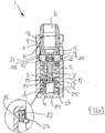
- Figure 1 shows a cross sectional view of an embodiment of a deactivating tappet 1 according to the invention.
- the deactivating tappet 1 has a housing 2 with an internal space 3 and a bottom 4.
- the tappet 1 has furthermore a main body 5, which is axially movable in the internal space 3 of the housing 2.
- the main body 5 has at the top a cavity 6 for accommodating for example a hydraulic lash adjuster.
- a first port 8 is provided, which connects the internal space 3 with a outer groove 9, which in turn is connected via a second port 10 to an outer groove 11 in the housing 2.
- a hydraulic fluid such as oil, can be supplied to the cavity 6 for use by for example the hydraulic lash adjuster.
- the main body 5 has at the bottom a stem 7, which is perpendicular to a first shoulder 12 on which primary spring 13 and secondary spring 14 are supported.
- a tubular body 15 with a second shoulder 16 is arranged around the stem 7 .
- the second shoulder 16 also supports the springs 13, 14 such that the primary body and secondary body are urged away from each other.
- a narrowed opening 17 is provided, through which the stem 7 extends.
- the tip of the stem 7 is provided with a locking ring 23 to prevent the tip of the stem 7 from shifting out of the narrowed opening 17.
- the locking ring 23 When the tappet 1 is fully extended, the locking ring 23 is kept in contact with a conic gauge surface of a ring-shim 27.
- the conic surface design of the ring-shim 27 allows to center the contact between the locking ring 23 and the ring-shim 27 itself, thus optimally distributing the contact pressure on the ring-shim 27 surface against the tubular body 15, and allowing centering of components around the main body stem 7.
- the main body 5 also comprises pins 18, 19 which are arranged in a radially extending channel.
- the pins 18, 19 are urged radially outward by a spring 20, such that the pins 18, 19 lock with the shelf groove 21 arranged in the internal wall of the housing 2.
- a third port 22 is provided in the housing 2, such that a controlling hydraulic fluid can be pumped against the spring loaded pins 18, 19, such that the pins 18, 19 are released from the shelf groove 21.
- Ventpet 1 Near the bottom 4 of the housing 2, ventilation openings 24, 25 are provided to prevent pressure build up, which could impede the function of the deactivating tappet 1.
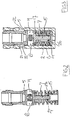
- Figure 2 shows part of the embodiment of figure 1 .
- the main body 5 and the secondary body 15 are telescopicaly connected to each other, such that the springs 13, 14 can be housed between the shoulders 12, 16. This enables one to handle the housing 2 and the internal parts 5, 15, 13, 14 separately.
- a filler ring 26 is positioned between the bottom 4 of the housing 2 and the secondary shoulder 16 of the internal parts 5, 15, 13, 14. With this filler ring 26 the lash between the pins 18, 19 and the shelf groove 21 is calibrated.
- Figure 3 shows the embodiment of figure 1 in deactivated state, wherein the third port has been supplied with pressurized fluid to urge the pins 18, 19 inwardly and release them from the shelf groove 21.
- the main body 5 can be moved axially relative to the housing 2 against the pressure of the springs 13, 14, such that the stem 7 slides telescopicly into the narrowed opening 17 of the secondary body 15.
- the function of the tappet 1 can be deactivated to, for example, turn off a valve in a valve train inside a combustion engine.
Landscapes
- Engineering & Computer Science (AREA)
- Mechanical Engineering (AREA)
- General Engineering & Computer Science (AREA)
- Valve-Gear Or Valve Arrangements (AREA)
- Valve Device For Special Equipments (AREA)
Description
- The invention relates to a deactivating tappet, for example for use in a valve train in a combustion engine, according to the preamble of claim 1. More specific, the invention relates to deactivating hydraulic lash adjusters. Such a deactivating tappet is known from
US 20060225684 . - Deactivating hydraulic lash adjusters are used in combustion engines to be able to turn cylinders on or off depending on the power demanded from the engine. The motor management system of such an engine decides whether all cylinders are required for providing the desired power, or that some of the cylinders can be deactivated. This deactivating is achieved by reducing or disabling the movement of the respective valves.
- For example
US 2011061615 discloses a deactivating hydraulic lash adjuster. This prior art hydraulic lash adjuster or tappet has a housing with a body slidably arranged in the housing. Springs are provided to urge the body into a rest position and locking pins extend radially from the body, to lock the body in a shelf groove arranged in the housing. - In the locked position, the tappet functions as a regular tappet and valves will be moved in sync with the cylinders. If a valve needs to be deactivated a hydraulic pressure is put on a groove on the outside of the tappet. This groove is in fluid communication via a port with the locking pins. The hydraulic pins are pressed inwardly by the hydraulic pressure, such that they are released from the pin shelf and the body can freely move inside the housing.
- Tappets are applied in all kinds of shapes and different sizes, such that for each application, the tappet needs to be redesigned and manufactured. Also the inner parts, such as springs, the body and the locking pins are designed depending on their application, for example the stroke the body can have in the housing in deactivated state.
- The body in locked state will have some lash, which needs to be tuned to the application. When manufacturing such deactivating tappets, each tappet needs to be calibrated for this internal lash. This results in calibrating the shelf groove in the housing, which makes calibrating a deactivating tappet a laborious task. In addition calibrating is furthermore done by adjusting the thickness of the retaining ring, with which the body is confined in the housing.
- It is an object of the invention to reduce or even remove the above mentioned disadvantages.
- This object is achieved according to the invention as claimed in claim 1.
- With the deactivation tappet according to the invention, the main body, secondary body and spring means can be handled as a separate unit, as the spring means are arranged between the first shoulder of the main body and the second shoulder of the secondary body. So, the housing can be designed and manufactured separately to the requirements of a specific engine, while the internal parts of the tappet can be designed and manufactured as a more generic separate part.
- The main body and secondary body are telescopicly arranged to each other, which means that the combination of the main and secondary body is able to become longer or shorter by having sections that slide inside one another.
- This guides the required movement inside the tappet when the locking means are disconnected from the pin shelf, while the spring means are kept between the shoulders and urge the main body and secondary body away from each other.
- The stem and the tubular body provide a telescopic arrangement and provide a guide for the spring means which are arranged around the stem and the tubular body.
- Preferably, in the tappet according to the invention, the free end of the stem comprises a locking ring for preventing the free end of the stem from shifting out of the narrowed opening. In this embodiment the telescopic stroke is limited by the locking ring, which ensures that the spring means can be arranged under tension between the shoulders in the extended position of main body and secondary body. This allows one to design the internal parts with some pretension.
- When the tappet is fully extended, the locking ring is preferably kept in contact with a conic gauge surface of a ring-shim. The conic surface design of the ring-shim allows to center the contact between the locking ring and the ring-shim itself, thus optimally distributing the contact pressure on the ring-shim surface against the secondary body. This ensures optimal contact among stacked components, and centering of components around the main body stem.
- In yet another embodiment of the tappet according to the invention a ventilation opening is arranged in the housing near and / or in the bottom of the bore. This ventilation opening ensures that the movement of the main body inside the housing is not impeded by any pressure build up as a result of tight tolerances between the main body and the housing.
- In a further preferred embodiment of the tappet according to the invention an outer circumferential groove is arranged on the housing and a channel extends between the outer circumferential groove and the shelf groove.
- Yet another preferred embodiment of the tappet according to the invention comprises a filler ring arranged on the bottom of the bore. This filler ring enables one to easily calibrate the
(Please continue on page 4, line 1 of the application as filed: "internal lash of the tappet. The thickness of the ring...")
internal lash of the tappet. The thickness of the ring defines the axial position of the main body and second body within the housing and accordingly the position of the locking means relative to the shelf groove. - In still another embodiment of the tappet the main body comprises in the end facing away from the secondary body a cavity for accommodating for example a hydraulic lash adjuster.
- Preferably, in the tappet according to the invention, the locking means comprise spring loaded pins arranged in a radially extending channel.
- These and other features of the invention will be elucidated in conjunction with the accompanying drawings.
-
Figure 1 shows a cross sectional view of an embodiment of a deactivating tappet according to the invention. -
Figure 2 shows part of the embodiment offigure 1 . -
Figure 3 shows the embodiment offigure 1 in deactivated state. -
Figure 1 shows a cross sectional view of an embodiment of a deactivating tappet 1 according to the invention. The deactivating tappet 1 has ahousing 2 with aninternal space 3 and a bottom 4. - The tappet 1 has furthermore a
main body 5, which is axially movable in theinternal space 3 of thehousing 2. Themain body 5 has at the top acavity 6 for accommodating for example a hydraulic lash adjuster. To this end afirst port 8 is provided, which connects theinternal space 3 with a outer groove 9, which in turn is connected via a second port 10 to anouter groove 11 in thehousing 2. Via thispath 8, 9, 10, 11 a hydraulic fluid, such as oil, can be supplied to thecavity 6 for use by for example the hydraulic lash adjuster. - The
main body 5 has at the bottom astem 7, which is perpendicular to a first shoulder 12 on whichprimary spring 13 and secondary spring 14 are supported. Around the stem 7 atubular body 15 with a second shoulder 16 is arranged. The second shoulder 16 also supports thesprings 13, 14 such that the primary body and secondary body are urged away from each other. At the top of thetubular body 15, a narrowedopening 17 is provided, through which thestem 7 extends. The tip of thestem 7 is provided with alocking ring 23 to prevent the tip of thestem 7 from shifting out of the narrowedopening 17. - When the tappet 1 is fully extended, the
locking ring 23 is kept in contact with a conic gauge surface of a ring-shim 27. The conic surface design of the ring-shim 27 allows to center the contact between thelocking ring 23 and the ring-shim 27 itself, thus optimally distributing the contact pressure on the ring-shim 27 surface against thetubular body 15, and allowing centering of components around themain body stem 7. - The
main body 5 also comprisespins 18, 19 which are arranged in a radially extending channel. Thepins 18, 19 are urged radially outward by aspring 20, such that thepins 18, 19 lock with theshelf groove 21 arranged in the internal wall of thehousing 2. Athird port 22 is provided in thehousing 2, such that a controlling hydraulic fluid can be pumped against the spring loadedpins 18, 19, such that thepins 18, 19 are released from theshelf groove 21. - Near the bottom 4 of the
housing 2,ventilation openings -
Figure 2 shows part of the embodiment offigure 1 . Themain body 5 and thesecondary body 15 are telescopicaly connected to each other, such that thesprings 13, 14 can be housed between the shoulders 12, 16. This enables one to handle thehousing 2 and theinternal parts - As shown in
figure 1 , afiller ring 26 is positioned between the bottom 4 of thehousing 2 and the secondary shoulder 16 of theinternal parts filler ring 26 the lash between thepins 18, 19 and theshelf groove 21 is calibrated. -
Figure 3 shows the embodiment offigure 1 in deactivated state, wherein the third port has been supplied with pressurized fluid to urge thepins 18, 19 inwardly and release them from theshelf groove 21.
As a result, themain body 5 can be moved axially relative to thehousing 2 against the pressure of thesprings 13, 14, such that thestem 7 slides telescopicly into the narrowedopening 17 of thesecondary body 15. - In this way, the function of the tappet 1 can be deactivated to, for example, turn off a valve in a valve train inside a combustion engine.
Claims (8)
- Deactivating tappet (1) comprising:- a housing (2) with a blind bore (3, 4) and with a shelf groove (21) arranged on the inner wall of the bore (3, 4);- a main body (5) slidably arranged in the bore (3, 4) of the housing (2), wherein the main body (5) comprises a first shoulder (12);- a secondary body (15, 16) telescopicly arranged to the main body (5) and having a second shoulder (16);- spring means (13, 14) arranged between the first shoulder (12) and the second shoulder (16);- locking means (18, 19, 20) extendable from the main body (5) for cooperation with the shelf groove (21), characterized in that the main body (5) comprises a stem (7) extending perpendicular from the first shoulder (12), wherein the secondary body (15, 16) comprises a tubular body (15) with the second shoulder (16) arranged at one end of the tubular body (15) and with a narrowed opening (17) at the other end, and wherein the stem (7) extends through the narrowed opening (17).
- Deactivating tappet (1) according to claim 1, wherein the free end of the stem (7) comprises a locking ring (23) for preventing the free end of the stem (7) from shifting out of the narrowed opening (17).
- Deactivating tappet (1) according to claim 2, wherein a ring-shim (27) having a conic gauge surface is arranged around the stem (7) and wherein the conic gauge surface is directed towards the locking ring (23).
- Deactivating tappet (1) according to any of the preceding claims, wherein a ventilation opening (24, 25) is arranged in the housing (2) near and / or in the bottom (4) of the bore (3, 4).
- Deactivating tappet (1) according to any of the preceding claims, wherein an outer circumferential groove is arranged on the housing (2) and a channel (22) extends between the outer circumferential groove and the shelf groove (12).
- Deactivating tappet (1) according to any of the preceding claims, comprising a filler ring (26) arranged on the bottom (4) of the bore (3, 4).
- Deactivating tappet (1) according to any of the preceding claims, wherein the main body (5) comprises in the end facing away from the secondary body (15, 16) a cavity (6) for accommodating a mechanical element to be deactivated, for example a hydraulic lash adjuster.
- Deactivating tappet (1) according to any of the preceding claims, wherein locking means (18, 19, 20) comprise spring (20) loaded pins (18, 19) arranged in a radially extending channel.
Applications Claiming Priority (1)
| Application Number | Priority Date | Filing Date | Title |
|---|---|---|---|
| GB1322406.8A GB2521388A (en) | 2013-12-18 | 2013-12-18 | Deactivating tappet |
Publications (2)
| Publication Number | Publication Date |
|---|---|
| EP2886813A1 EP2886813A1 (en) | 2015-06-24 |
| EP2886813B1 true EP2886813B1 (en) | 2017-08-16 |
Family
ID=50071010
Family Applications (1)
| Application Number | Title | Priority Date | Filing Date |
|---|---|---|---|
| EP14198338.7A Active EP2886813B1 (en) | 2013-12-18 | 2014-12-16 | Deactivating tappet |
Country Status (4)
| Country | Link |
|---|---|
| US (1) | US9976453B2 (en) |
| EP (1) | EP2886813B1 (en) |
| CN (1) | CN104727877B (en) |
| GB (1) | GB2521388A (en) |
Families Citing this family (3)
| Publication number | Priority date | Publication date | Assignee | Title |
|---|---|---|---|---|
| JP6273837B2 (en) * | 2013-12-27 | 2018-02-07 | マツダ株式会社 | Hydraulic supply device for valve stop mechanism |
| CN107208500A (en) | 2015-01-28 | 2017-09-26 | 伊顿公司 | Axial cam displacement valve assembly with other discrete valve event |
| US10323550B1 (en) * | 2018-03-14 | 2019-06-18 | Ford Global Technologies, Llc | Protection for hydraulic lifters |
Family Cites Families (17)
| Publication number | Priority date | Publication date | Assignee | Title |
|---|---|---|---|---|
| US2590719A (en) * | 1949-05-03 | 1952-03-25 | Ford Motor Co | Rotation permitting assembly for poppet valves |
| DE4436952A1 (en) * | 1994-10-15 | 1996-04-18 | Schaeffler Waelzlager Kg | Switchable tappet of a valve train of an internal combustion engine |
| JP4163315B2 (en) * | 1999-01-11 | 2008-10-08 | 本田技研工業株式会社 | Engine valve gear |
| US6513470B1 (en) * | 2000-10-20 | 2003-02-04 | Delphi Technologies, Inc. | Deactivation hydraulic valve lifter |
| US6497207B2 (en) * | 2000-10-20 | 2002-12-24 | Delphi Technologies, Inc. | Deactivation roller hydraulic valve lifter |
| US20030150859A1 (en) * | 2000-03-14 | 2003-08-14 | Heinrich Reutter | Sealing cap |
| DE10310776A1 (en) * | 2002-03-13 | 2003-11-13 | Stanadyne Corp | Valve actuation adjustment device with deactivation of locking balls |
| DE10300724A1 (en) * | 2003-01-11 | 2004-07-29 | Ina-Schaeffler Kg | Switchable cam follower of a valve train of an internal combustion engine |
| US6945204B2 (en) * | 2003-11-12 | 2005-09-20 | General Motors Corporation | Engine valve actuator assembly |
| DE102004040808A1 (en) * | 2004-08-24 | 2006-03-30 | Ina-Schaeffler Kg | Switchable cam follower |
| US7246585B2 (en) * | 2005-04-12 | 2007-07-24 | Delphi Technologies, Inc. | Valve-deactivating hydraulic lifter having a vented internal lost motion spring |
| FR2889728B1 (en) | 2005-08-10 | 2007-10-05 | Staubli Faverges Sca | CONNECTOR ASSEMBLY FOR FLUIDIC CIRCUIT |
| DE102006002967A1 (en) * | 2006-01-21 | 2007-08-09 | Schaeffler Kg | Valve train of an internal combustion engine |
| US8161929B2 (en) | 2007-11-21 | 2012-04-24 | Schaeffler Kg | Switchable tappet |
| US8151752B2 (en) * | 2008-02-11 | 2012-04-10 | Delphi Technologies, Inc. | Deactivating hydraulic lash adjuster for oriented mounting in an engine |
| DE102009033634A1 (en) * | 2009-07-17 | 2011-01-20 | Schaeffler Technologies Gmbh & Co. Kg | Switchable rocker arm for valve train of internal combustion engine, has outer lever and inner lever which are supported to each other at end on axis relative to deviation movement |
| US8196556B2 (en) * | 2009-09-17 | 2012-06-12 | Delphi Technologies, Inc. | Apparatus and method for setting mechanical lash in a valve-deactivating hydraulic lash adjuster |
-
2013
- 2013-12-18 GB GB1322406.8A patent/GB2521388A/en not_active Withdrawn
-
2014
- 2014-12-16 EP EP14198338.7A patent/EP2886813B1/en active Active
- 2014-12-18 CN CN201410797564.2A patent/CN104727877B/en active Active
- 2014-12-18 US US14/574,407 patent/US9976453B2/en active Active
Also Published As
| Publication number | Publication date |
|---|---|
| US9976453B2 (en) | 2018-05-22 |
| CN104727877A (en) | 2015-06-24 |
| EP2886813A1 (en) | 2015-06-24 |
| US20150167507A1 (en) | 2015-06-18 |
| CN104727877B (en) | 2019-02-22 |
| GB201322406D0 (en) | 2014-02-05 |
| GB2521388A (en) | 2015-06-24 |
Similar Documents
| Publication | Publication Date | Title |
|---|---|---|
| EP2430307B1 (en) | Valve unit for a high-pressure piston fuel pump and pump comprising this valve unit | |
| EP3161279B1 (en) | Hydraulic valve for an internal combustion engine | |
| EP3353389B1 (en) | Valve train carrier assembly | |
| US8899271B2 (en) | Pressure accumulator | |
| EP2886813A1 (en) | Deactivating tappet | |
| US20150267571A1 (en) | Control valve for a camshaft adjuster system | |
| US20100059001A1 (en) | Switchable support element for a valve train of an internal combustion engine | |
| US8082896B2 (en) | Switchable support element for a valve train of an internal combustion engine | |
| EP1344900A2 (en) | A multicylinder engine with valve variable actuation, and an improved valve braking device therefor | |
| US8997702B2 (en) | Actuator unit with reduced actuator pin friction | |
| US8826875B2 (en) | Actuator of an electrohydraulic gas exchange valve drive of an internal combustion engine | |
| US10119430B2 (en) | Transmission element for reciprocating piston internal combustion engines | |
| US9790820B2 (en) | Switching oil gallery de-aeration | |
| US9920664B2 (en) | Actuator for an electrohydraulic gas-exchange valve train of a combustion engine | |
| US9021936B2 (en) | Ventless actuator lock | |
| US9482122B2 (en) | Detent assembly and a method of assembling the detent assembly | |
| US9222377B2 (en) | Volume store | |
| US10352283B2 (en) | Internal combustion engine fuel, preferably diesel fuel, feed pump assembly | |
| CN108204259B (en) | Independent hydraulic support element | |
| US9617877B2 (en) | Valve opening and closing timing control device | |
| US20150083062A1 (en) | Outer housing for a hydraulic lash adjuster with tapered oil feed annulus | |
| US10184365B2 (en) | Sliding cam system having two-stage actuator stroke | |
| CN119096037A (en) | Dual pressure chamber assembly | |
| US12012874B2 (en) | Switching element for a valve train of an internal combustion engine | |
| US9664072B2 (en) | Switchable hydraulic lash adjuster with external spring and solid stop |
Legal Events
| Date | Code | Title | Description |
|---|---|---|---|
| PUAI | Public reference made under article 153(3) epc to a published international application that has entered the european phase |
Free format text: ORIGINAL CODE: 0009012 |
|
| 17P | Request for examination filed |
Effective date: 20141216 |
|
| AK | Designated contracting states |
Kind code of ref document: A1 Designated state(s): AL AT BE BG CH CY CZ DE DK EE ES FI FR GB GR HR HU IE IS IT LI LT LU LV MC MK MT NL NO PL PT RO RS SE SI SK SM TR |
|
| AX | Request for extension of the european patent |
Extension state: BA ME |
|
| R17P | Request for examination filed (corrected) |
Effective date: 20151217 |
|
| RBV | Designated contracting states (corrected) |
Designated state(s): AL AT BE BG CH CY CZ DE DK EE ES FI FR GB GR HR HU IE IS IT LI LT LU LV MC MK MT NL NO PL PT RO RS SE SI SK SM TR |
|
| GRAP | Despatch of communication of intention to grant a patent |
Free format text: ORIGINAL CODE: EPIDOSNIGR1 |
|
| INTG | Intention to grant announced |
Effective date: 20161117 |
|
| GRAS | Grant fee paid |
Free format text: ORIGINAL CODE: EPIDOSNIGR3 |
|
| GRAA | (expected) grant |
Free format text: ORIGINAL CODE: 0009210 |
|
| AK | Designated contracting states |
Kind code of ref document: B1 Designated state(s): AL AT BE BG CH CY CZ DE DK EE ES FI FR GB GR HR HU IE IS IT LI LT LU LV MC MK MT NL NO PL PT RO RS SE SI SK SM TR |
|
| REG | Reference to a national code |
Ref country code: GB Ref legal event code: FG4D |
|
| REG | Reference to a national code |
Ref country code: CH Ref legal event code: EP |
|
| REG | Reference to a national code |
Ref country code: IE Ref legal event code: FG4D |
|
| REG | Reference to a national code |
Ref country code: AT Ref legal event code: REF Ref document number: 919275 Country of ref document: AT Kind code of ref document: T Effective date: 20170915 |
|
| REG | Reference to a national code |
Ref country code: DE Ref legal event code: R096 Ref document number: 602014013151 Country of ref document: DE |
|
| REG | Reference to a national code |
Ref country code: FR Ref legal event code: PLFP Year of fee payment: 4 |
|
| REG | Reference to a national code |
Ref country code: SE Ref legal event code: TRGR |
|
| REG | Reference to a national code |
Ref country code: NL Ref legal event code: MP Effective date: 20170816 |
|
| REG | Reference to a national code |
Ref country code: LT Ref legal event code: MG4D |
|
| REG | Reference to a national code |
Ref country code: AT Ref legal event code: MK05 Ref document number: 919275 Country of ref document: AT Kind code of ref document: T Effective date: 20170816 |
|
| PG25 | Lapsed in a contracting state [announced via postgrant information from national office to epo] |
Ref country code: NL Free format text: LAPSE BECAUSE OF FAILURE TO SUBMIT A TRANSLATION OF THE DESCRIPTION OR TO PAY THE FEE WITHIN THE PRESCRIBED TIME-LIMIT Effective date: 20170816 Ref country code: AT Free format text: LAPSE BECAUSE OF FAILURE TO SUBMIT A TRANSLATION OF THE DESCRIPTION OR TO PAY THE FEE WITHIN THE PRESCRIBED TIME-LIMIT Effective date: 20170816 Ref country code: NO Free format text: LAPSE BECAUSE OF FAILURE TO SUBMIT A TRANSLATION OF THE DESCRIPTION OR TO PAY THE FEE WITHIN THE PRESCRIBED TIME-LIMIT Effective date: 20171116 Ref country code: LT Free format text: LAPSE BECAUSE OF FAILURE TO SUBMIT A TRANSLATION OF THE DESCRIPTION OR TO PAY THE FEE WITHIN THE PRESCRIBED TIME-LIMIT Effective date: 20170816 Ref country code: FI Free format text: LAPSE BECAUSE OF FAILURE TO SUBMIT A TRANSLATION OF THE DESCRIPTION OR TO PAY THE FEE WITHIN THE PRESCRIBED TIME-LIMIT Effective date: 20170816 |
|
| PG25 | Lapsed in a contracting state [announced via postgrant information from national office to epo] |
Ref country code: IS Free format text: LAPSE BECAUSE OF FAILURE TO SUBMIT A TRANSLATION OF THE DESCRIPTION OR TO PAY THE FEE WITHIN THE PRESCRIBED TIME-LIMIT Effective date: 20171216 Ref country code: RS Free format text: LAPSE BECAUSE OF FAILURE TO SUBMIT A TRANSLATION OF THE DESCRIPTION OR TO PAY THE FEE WITHIN THE PRESCRIBED TIME-LIMIT Effective date: 20170816 Ref country code: ES Free format text: LAPSE BECAUSE OF FAILURE TO SUBMIT A TRANSLATION OF THE DESCRIPTION OR TO PAY THE FEE WITHIN THE PRESCRIBED TIME-LIMIT Effective date: 20170816 Ref country code: GR Free format text: LAPSE BECAUSE OF FAILURE TO SUBMIT A TRANSLATION OF THE DESCRIPTION OR TO PAY THE FEE WITHIN THE PRESCRIBED TIME-LIMIT Effective date: 20171117 Ref country code: LV Free format text: LAPSE BECAUSE OF FAILURE TO SUBMIT A TRANSLATION OF THE DESCRIPTION OR TO PAY THE FEE WITHIN THE PRESCRIBED TIME-LIMIT Effective date: 20170816 Ref country code: BG Free format text: LAPSE BECAUSE OF FAILURE TO SUBMIT A TRANSLATION OF THE DESCRIPTION OR TO PAY THE FEE WITHIN THE PRESCRIBED TIME-LIMIT Effective date: 20171116 Ref country code: PL Free format text: LAPSE BECAUSE OF FAILURE TO SUBMIT A TRANSLATION OF THE DESCRIPTION OR TO PAY THE FEE WITHIN THE PRESCRIBED TIME-LIMIT Effective date: 20170816 |
|
| PG25 | Lapsed in a contracting state [announced via postgrant information from national office to epo] |
Ref country code: RO Free format text: LAPSE BECAUSE OF FAILURE TO SUBMIT A TRANSLATION OF THE DESCRIPTION OR TO PAY THE FEE WITHIN THE PRESCRIBED TIME-LIMIT Effective date: 20170816 Ref country code: CZ Free format text: LAPSE BECAUSE OF FAILURE TO SUBMIT A TRANSLATION OF THE DESCRIPTION OR TO PAY THE FEE WITHIN THE PRESCRIBED TIME-LIMIT Effective date: 20170816 Ref country code: DK Free format text: LAPSE BECAUSE OF FAILURE TO SUBMIT A TRANSLATION OF THE DESCRIPTION OR TO PAY THE FEE WITHIN THE PRESCRIBED TIME-LIMIT Effective date: 20170816 |
|
| REG | Reference to a national code |
Ref country code: DE Ref legal event code: R097 Ref document number: 602014013151 Country of ref document: DE |
|
| PG25 | Lapsed in a contracting state [announced via postgrant information from national office to epo] |
Ref country code: EE Free format text: LAPSE BECAUSE OF FAILURE TO SUBMIT A TRANSLATION OF THE DESCRIPTION OR TO PAY THE FEE WITHIN THE PRESCRIBED TIME-LIMIT Effective date: 20170816 Ref country code: SK Free format text: LAPSE BECAUSE OF FAILURE TO SUBMIT A TRANSLATION OF THE DESCRIPTION OR TO PAY THE FEE WITHIN THE PRESCRIBED TIME-LIMIT Effective date: 20170816 Ref country code: SM Free format text: LAPSE BECAUSE OF FAILURE TO SUBMIT A TRANSLATION OF THE DESCRIPTION OR TO PAY THE FEE WITHIN THE PRESCRIBED TIME-LIMIT Effective date: 20170816 |
|
| PLBE | No opposition filed within time limit |
Free format text: ORIGINAL CODE: 0009261 |
|
| STAA | Information on the status of an ep patent application or granted ep patent |
Free format text: STATUS: NO OPPOSITION FILED WITHIN TIME LIMIT |
|
| 26N | No opposition filed |
Effective date: 20180517 |
|
| REG | Reference to a national code |
Ref country code: CH Ref legal event code: PL |
|
| PG25 | Lapsed in a contracting state [announced via postgrant information from national office to epo] |
Ref country code: SI Free format text: LAPSE BECAUSE OF FAILURE TO SUBMIT A TRANSLATION OF THE DESCRIPTION OR TO PAY THE FEE WITHIN THE PRESCRIBED TIME-LIMIT Effective date: 20170816 |
|
| REG | Reference to a national code |
Ref country code: IE Ref legal event code: MM4A |
|
| PG25 | Lapsed in a contracting state [announced via postgrant information from national office to epo] |
Ref country code: MT Free format text: LAPSE BECAUSE OF NON-PAYMENT OF DUE FEES Effective date: 20171216 Ref country code: LU Free format text: LAPSE BECAUSE OF NON-PAYMENT OF DUE FEES Effective date: 20171216 |
|
| REG | Reference to a national code |
Ref country code: BE Ref legal event code: MM Effective date: 20171231 |
|
| PG25 | Lapsed in a contracting state [announced via postgrant information from national office to epo] |
Ref country code: IE Free format text: LAPSE BECAUSE OF NON-PAYMENT OF DUE FEES Effective date: 20171216 |
|
| PG25 | Lapsed in a contracting state [announced via postgrant information from national office to epo] |
Ref country code: BE Free format text: LAPSE BECAUSE OF NON-PAYMENT OF DUE FEES Effective date: 20171231 Ref country code: CH Free format text: LAPSE BECAUSE OF NON-PAYMENT OF DUE FEES Effective date: 20171231 Ref country code: LI Free format text: LAPSE BECAUSE OF NON-PAYMENT OF DUE FEES Effective date: 20171231 |
|
| REG | Reference to a national code |
Ref country code: GB Ref legal event code: 732E Free format text: REGISTERED BETWEEN 20181108 AND 20181114 |
|
| REG | Reference to a national code |
Ref country code: DE Ref legal event code: R081 Ref document number: 602014013151 Country of ref document: DE Owner name: EATON INTELLIGENT POWER LIMITED, IE Free format text: FORMER OWNER: EATON S.R.L., TORINO, IT |
|
| PG25 | Lapsed in a contracting state [announced via postgrant information from national office to epo] |
Ref country code: HU Free format text: LAPSE BECAUSE OF FAILURE TO SUBMIT A TRANSLATION OF THE DESCRIPTION OR TO PAY THE FEE WITHIN THE PRESCRIBED TIME-LIMIT; INVALID AB INITIO Effective date: 20141216 Ref country code: MC Free format text: LAPSE BECAUSE OF FAILURE TO SUBMIT A TRANSLATION OF THE DESCRIPTION OR TO PAY THE FEE WITHIN THE PRESCRIBED TIME-LIMIT Effective date: 20170816 |
|
| PG25 | Lapsed in a contracting state [announced via postgrant information from national office to epo] |
Ref country code: CY Free format text: LAPSE BECAUSE OF FAILURE TO SUBMIT A TRANSLATION OF THE DESCRIPTION OR TO PAY THE FEE WITHIN THE PRESCRIBED TIME-LIMIT Effective date: 20170816 |
|
| PG25 | Lapsed in a contracting state [announced via postgrant information from national office to epo] |
Ref country code: MK Free format text: LAPSE BECAUSE OF FAILURE TO SUBMIT A TRANSLATION OF THE DESCRIPTION OR TO PAY THE FEE WITHIN THE PRESCRIBED TIME-LIMIT Effective date: 20170816 |
|
| PG25 | Lapsed in a contracting state [announced via postgrant information from national office to epo] |
Ref country code: TR Free format text: LAPSE BECAUSE OF FAILURE TO SUBMIT A TRANSLATION OF THE DESCRIPTION OR TO PAY THE FEE WITHIN THE PRESCRIBED TIME-LIMIT Effective date: 20170816 |
|
| PG25 | Lapsed in a contracting state [announced via postgrant information from national office to epo] |
Ref country code: PT Free format text: LAPSE BECAUSE OF FAILURE TO SUBMIT A TRANSLATION OF THE DESCRIPTION OR TO PAY THE FEE WITHIN THE PRESCRIBED TIME-LIMIT Effective date: 20170816 |
|
| PG25 | Lapsed in a contracting state [announced via postgrant information from national office to epo] |
Ref country code: HR Free format text: LAPSE BECAUSE OF FAILURE TO SUBMIT A TRANSLATION OF THE DESCRIPTION OR TO PAY THE FEE WITHIN THE PRESCRIBED TIME-LIMIT Effective date: 20170816 |
|
| PG25 | Lapsed in a contracting state [announced via postgrant information from national office to epo] |
Ref country code: AL Free format text: LAPSE BECAUSE OF FAILURE TO SUBMIT A TRANSLATION OF THE DESCRIPTION OR TO PAY THE FEE WITHIN THE PRESCRIBED TIME-LIMIT Effective date: 20170816 |
|
| PGFP | Annual fee paid to national office [announced via postgrant information from national office to epo] |
Ref country code: FR Payment date: 20201120 Year of fee payment: 7 Ref country code: SE Payment date: 20201124 Year of fee payment: 7 Ref country code: IT Payment date: 20201123 Year of fee payment: 7 Ref country code: GB Payment date: 20201123 Year of fee payment: 7 |
|
| REG | Reference to a national code |
Ref country code: SE Ref legal event code: EUG |
|
| GBPC | Gb: european patent ceased through non-payment of renewal fee |
Effective date: 20211216 |
|
| PG25 | Lapsed in a contracting state [announced via postgrant information from national office to epo] |
Ref country code: SE Free format text: LAPSE BECAUSE OF NON-PAYMENT OF DUE FEES Effective date: 20211217 Ref country code: GB Free format text: LAPSE BECAUSE OF NON-PAYMENT OF DUE FEES Effective date: 20211216 |
|
| PG25 | Lapsed in a contracting state [announced via postgrant information from national office to epo] |
Ref country code: FR Free format text: LAPSE BECAUSE OF NON-PAYMENT OF DUE FEES Effective date: 20211231 |
|
| PG25 | Lapsed in a contracting state [announced via postgrant information from national office to epo] |
Ref country code: IT Free format text: LAPSE BECAUSE OF NON-PAYMENT OF DUE FEES Effective date: 20211216 |
|
| P01 | Opt-out of the competence of the unified patent court (upc) registered |
Effective date: 20230521 |
|
| PGFP | Annual fee paid to national office [announced via postgrant information from national office to epo] |
Ref country code: DE Payment date: 20251126 Year of fee payment: 12 |