EP2886485B1 - Sealing cover for containers with increased heat resistance, easy-opening performance and sealability - Google Patents
Sealing cover for containers with increased heat resistance, easy-opening performance and sealability Download PDFInfo
- Publication number
- EP2886485B1 EP2886485B1 EP14156926.9A EP14156926A EP2886485B1 EP 2886485 B1 EP2886485 B1 EP 2886485B1 EP 14156926 A EP14156926 A EP 14156926A EP 2886485 B1 EP2886485 B1 EP 2886485B1
- Authority
- EP
- European Patent Office
- Prior art keywords
- container
- sealing cover
- heat
- layer
- opening
- Prior art date
- Legal status (The legal status is an assumption and is not a legal conclusion. Google has not performed a legal analysis and makes no representation as to the accuracy of the status listed.)
- Active
Links
Images


Classifications
-
- B—PERFORMING OPERATIONS; TRANSPORTING
- B65—CONVEYING; PACKING; STORING; HANDLING THIN OR FILAMENTARY MATERIAL
- B65D—CONTAINERS FOR STORAGE OR TRANSPORT OF ARTICLES OR MATERIALS, e.g. BAGS, BARRELS, BOTTLES, BOXES, CANS, CARTONS, CRATES, DRUMS, JARS, TANKS, HOPPERS, FORWARDING CONTAINERS; ACCESSORIES, CLOSURES, OR FITTINGS THEREFOR; PACKAGING ELEMENTS; PACKAGES
- B65D53/00—Sealing or packing elements; Sealings formed by liquid or plastics material
- B65D53/06—Sealings formed by liquid or plastic material
-
- B—PERFORMING OPERATIONS; TRANSPORTING
- B65—CONVEYING; PACKING; STORING; HANDLING THIN OR FILAMENTARY MATERIAL
- B65D—CONTAINERS FOR STORAGE OR TRANSPORT OF ARTICLES OR MATERIALS, e.g. BAGS, BARRELS, BOTTLES, BOXES, CANS, CARTONS, CRATES, DRUMS, JARS, TANKS, HOPPERS, FORWARDING CONTAINERS; ACCESSORIES, CLOSURES, OR FITTINGS THEREFOR; PACKAGING ELEMENTS; PACKAGES
- B65D41/00—Caps, e.g. crown caps or crown seals, i.e. members having parts arranged for engagement with the external periphery of a neck or wall defining a pouring opening or discharge aperture; Protective cap-like covers for closure members, e.g. decorative covers of metal foil or paper
- B65D41/02—Caps or cap-like covers without lines of weakness, tearing strips, tags, or like opening or removal devices
- B65D41/10—Caps or cap-like covers adapted to be secured in position by permanent deformation of the wall-engaging parts
- B65D41/14—Caps or cap-like covers adapted to be secured in position by permanent deformation of the wall-engaging parts made of metallic foil or like thin flexible material
-
- B—PERFORMING OPERATIONS; TRANSPORTING
- B32—LAYERED PRODUCTS
- B32B—LAYERED PRODUCTS, i.e. PRODUCTS BUILT-UP OF STRATA OF FLAT OR NON-FLAT, e.g. CELLULAR OR HONEYCOMB, FORM
- B32B27/00—Layered products comprising a layer of synthetic resin
- B32B27/06—Layered products comprising a layer of synthetic resin as the main or only constituent of a layer, which is next to another layer of the same or of a different material
- B32B27/08—Layered products comprising a layer of synthetic resin as the main or only constituent of a layer, which is next to another layer of the same or of a different material of synthetic resin
-
- B—PERFORMING OPERATIONS; TRANSPORTING
- B65—CONVEYING; PACKING; STORING; HANDLING THIN OR FILAMENTARY MATERIAL
- B65D—CONTAINERS FOR STORAGE OR TRANSPORT OF ARTICLES OR MATERIALS, e.g. BAGS, BARRELS, BOTTLES, BOXES, CANS, CARTONS, CRATES, DRUMS, JARS, TANKS, HOPPERS, FORWARDING CONTAINERS; ACCESSORIES, CLOSURES, OR FITTINGS THEREFOR; PACKAGING ELEMENTS; PACKAGES
- B65D41/00—Caps, e.g. crown caps or crown seals, i.e. members having parts arranged for engagement with the external periphery of a neck or wall defining a pouring opening or discharge aperture; Protective cap-like covers for closure members, e.g. decorative covers of metal foil or paper
- B65D41/02—Caps or cap-like covers without lines of weakness, tearing strips, tags, or like opening or removal devices
- B65D41/20—Caps or cap-like covers with membranes, e.g. arranged to be pierced
-
- B—PERFORMING OPERATIONS; TRANSPORTING
- B65—CONVEYING; PACKING; STORING; HANDLING THIN OR FILAMENTARY MATERIAL
- B65D—CONTAINERS FOR STORAGE OR TRANSPORT OF ARTICLES OR MATERIALS, e.g. BAGS, BARRELS, BOTTLES, BOXES, CANS, CARTONS, CRATES, DRUMS, JARS, TANKS, HOPPERS, FORWARDING CONTAINERS; ACCESSORIES, CLOSURES, OR FITTINGS THEREFOR; PACKAGING ELEMENTS; PACKAGES
- B65D41/00—Caps, e.g. crown caps or crown seals, i.e. members having parts arranged for engagement with the external periphery of a neck or wall defining a pouring opening or discharge aperture; Protective cap-like covers for closure members, e.g. decorative covers of metal foil or paper
- B65D41/32—Caps or cap-like covers with lines of weakness, tearing-strips, tags, or like opening or removal devices, e.g. to facilitate formation of pouring openings
- B65D41/325—Caps or cap-like covers with lines of weakness, tearing-strips, tags, or like opening or removal devices, e.g. to facilitate formation of pouring openings with integral internal sealing means
-
- B—PERFORMING OPERATIONS; TRANSPORTING
- B65—CONVEYING; PACKING; STORING; HANDLING THIN OR FILAMENTARY MATERIAL
- B65D—CONTAINERS FOR STORAGE OR TRANSPORT OF ARTICLES OR MATERIALS, e.g. BAGS, BARRELS, BOTTLES, BOXES, CANS, CARTONS, CRATES, DRUMS, JARS, TANKS, HOPPERS, FORWARDING CONTAINERS; ACCESSORIES, CLOSURES, OR FITTINGS THEREFOR; PACKAGING ELEMENTS; PACKAGES
- B65D51/00—Closures not otherwise provided for
- B65D51/18—Arrangements of closures with protective outer cap-like covers or of two or more co-operating closures
- B65D51/20—Caps, lids, or covers co-operating with an inner closure arranged to be opened by piercing, cutting, or tearing
-
- B—PERFORMING OPERATIONS; TRANSPORTING
- B65—CONVEYING; PACKING; STORING; HANDLING THIN OR FILAMENTARY MATERIAL
- B65D—CONTAINERS FOR STORAGE OR TRANSPORT OF ARTICLES OR MATERIALS, e.g. BAGS, BARRELS, BOTTLES, BOXES, CANS, CARTONS, CRATES, DRUMS, JARS, TANKS, HOPPERS, FORWARDING CONTAINERS; ACCESSORIES, CLOSURES, OR FITTINGS THEREFOR; PACKAGING ELEMENTS; PACKAGES
- B65D77/00—Packages formed by enclosing articles or materials in preformed containers, e.g. boxes, cartons, sacks or bags
- B65D77/10—Container closures formed after filling
- B65D77/20—Container closures formed after filling by applying separate lids or covers, i.e. flexible membrane or foil-like covers
- B65D77/2024—Container closures formed after filling by applying separate lids or covers, i.e. flexible membrane or foil-like covers the cover being welded or adhered to the container
- B65D77/2028—Means for opening the cover other than, or in addition to, a pull tab
- B65D77/2032—Means for opening the cover other than, or in addition to, a pull tab by peeling or tearing the cover from the container
- B65D77/2044—Means for opening the cover other than, or in addition to, a pull tab by peeling or tearing the cover from the container whereby a layer of the container or cover fails, e.g. cohesive failure
-
- B—PERFORMING OPERATIONS; TRANSPORTING
- B65—CONVEYING; PACKING; STORING; HANDLING THIN OR FILAMENTARY MATERIAL
- B65D—CONTAINERS FOR STORAGE OR TRANSPORT OF ARTICLES OR MATERIALS, e.g. BAGS, BARRELS, BOTTLES, BOXES, CANS, CARTONS, CRATES, DRUMS, JARS, TANKS, HOPPERS, FORWARDING CONTAINERS; ACCESSORIES, CLOSURES, OR FITTINGS THEREFOR; PACKAGING ELEMENTS; PACKAGES
- B65D77/00—Packages formed by enclosing articles or materials in preformed containers, e.g. boxes, cartons, sacks or bags
- B65D77/10—Container closures formed after filling
- B65D77/20—Container closures formed after filling by applying separate lids or covers, i.e. flexible membrane or foil-like covers
- B65D77/2024—Container closures formed after filling by applying separate lids or covers, i.e. flexible membrane or foil-like covers the cover being welded or adhered to the container
- B65D77/2068—Means for reclosing the cover after its first opening
- B65D77/2096—Adhesive means
-
- B—PERFORMING OPERATIONS; TRANSPORTING
- B65—CONVEYING; PACKING; STORING; HANDLING THIN OR FILAMENTARY MATERIAL
- B65D—CONTAINERS FOR STORAGE OR TRANSPORT OF ARTICLES OR MATERIALS, e.g. BAGS, BARRELS, BOTTLES, BOXES, CANS, CARTONS, CRATES, DRUMS, JARS, TANKS, HOPPERS, FORWARDING CONTAINERS; ACCESSORIES, CLOSURES, OR FITTINGS THEREFOR; PACKAGING ELEMENTS; PACKAGES
- B65D2251/00—Details relating to container closures
- B65D2251/0003—Two or more closures
- B65D2251/0068—Lower closure
- B65D2251/0093—Membrane
-
- B—PERFORMING OPERATIONS; TRANSPORTING
- B65—CONVEYING; PACKING; STORING; HANDLING THIN OR FILAMENTARY MATERIAL
- B65D—CONTAINERS FOR STORAGE OR TRANSPORT OF ARTICLES OR MATERIALS, e.g. BAGS, BARRELS, BOTTLES, BOXES, CANS, CARTONS, CRATES, DRUMS, JARS, TANKS, HOPPERS, FORWARDING CONTAINERS; ACCESSORIES, CLOSURES, OR FITTINGS THEREFOR; PACKAGING ELEMENTS; PACKAGES
- B65D2577/00—Packages formed by enclosing articles or materials in preformed containers, e.g. boxes, cartons, sacks, bags
- B65D2577/10—Container closures formed after filling
- B65D2577/20—Container closures formed after filling by applying separate lids or covers
- B65D2577/2041—Pull tabs
- B65D2577/205—Pull tabs integral with the closure
Definitions
- the present invention relates generally to sealing covers, according to the preamble of claim 1, which seal apertures of containers made of plastic, glass or the like and, more particularly, to a sealing cover for containers which has improved heat resistance, easy-opening performance and sealability.
- containers made of plastic, glass or the like have apertures.
- the apertures of the containers must be sealed to protect contents contained in the containers or prevent fluid contents from leaking during distribution process of products.
- Typical caps, caps provided with shock absorption substances on inner surfaces thereof, heat sealing covers sealed on apertures of containers by thermal compression bonding, etc. are being used as sealers for sealing the apertures of the containers.
- an elastic foamed packing is a representative example of the shock absorption substances provided in the caps.
- Conduction type heat-seals, high-frequency induction heating seals, etc. are used as the heat sealing covers.
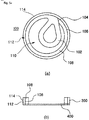
- FIGS. 1(a) and 1(b) show examples of a conventional heat sealing cover having an opening tab.
- FIG. 1(a) illustrates a heat sealing cover 20 which is configured such that a central portion thereof can be opened by means of an opening tab 10.
- an aperture of a container can be opened by the opening tab 10.
- it is difficult to pull contents out because the area of the open portion is comparatively small.
- FIG. 1(b) illustrates a heat sealing cover 30 which opens in a peeling manner.
- the area of an opening portion can be as large as desired.
- the sealing function is lost. That is, after the heat sealing cover 30 is peeled off, even when the container is covered with a cap again, leakage of fluid contents may be caused because of reduced close-contactability between the container and the cap.
- the conventional heat sealing covers shown in FIGS. 1(a) and 1(b) are not adapted for retort products because of low heat resistance.
- Retort products are generally treated by vacuum sterilization at a high temperature of 130°C or more after the apertures of containers therefor have been sealed. If the heat resistance of the heat sealing cover is unsatisfactory, internal heat of the container is diffused to the outside through the heat sealing cover. As a result, the cap, inside which the heat sealing cover is disposed, may be damaged by heat transferred thereto through the heat sealing cover.
- US 2008/073308 A1 (Yousif Pule, 2008.03.27 .) discloses a container seal including a metal-free tab member.
- the container seal comprises a flexible, metal-free cover sheet and a flexible sealant sheet.
- the cover sheet comprises at least one layer of a flexible sheet material and includes a body portion that is sized and shaped to at least cover a container finish and has at least one metal-free tab portion extending from the periphery of the body portion.
- a sealing member for a container comprises a heat actuated sealant or adhesive layer for securing the sealing member to a container, a metal foil layer over and covering and adhesively bonded to the heat actuated sealant or adhesive layer, and a polyethylene or polypropylene foam or film layer over and covering and adhesively bonded to the foil layer.
- JP H054642 A (Toppan Printing Co Ltd, 1993.01.14) discloses a sealing cover for containers comprising an opening guide cutting element which is substantially circular.
- an object of the present invention is to provide a sealing cover for containers which has superior heat resistance so that it can be applied not only to a container for general purposes but also to a container for retort products.
- Another object of the present invention is to provide a sealing cover for containers which has an opening structure capable of easy-opening and an opening area as large as needed to facilitate removal of contents from the container.
- a further object of the present invention is to provide a sealing cover for containers which can provide a secondary sealing effect in which because a part of the sealing cover remains on a lip of an aperture of the container in an annular shape after the sealing cover has opened, when the container is covered with a cap again, the close contact between the container and the cap can be ensured by the elasticity and the shock absorbing effect of the remaining part of the sealing cover, thus reliably preventing contents from leaking.
- the present invention provides a sealing cover which is suitable for sealing an aperture of a container by heat adhesion, the sealing cover having an upper layer provided with an opening tab and a lower layer comprising an aluminum foil and a heat sealing adhesive layer for providing thermal adhesion to the container, the upper layer and the lower layer being integrated with each other via thermal adhesion using a heat adhesive resin or film.
- the upper layer includes:
- the upper layer may include a surface layer made of a polyester or polypropylene film that has no heat adhesive properties and has a thickness ranging from 0.012 mm to 0.04 mm.
- the upper layer may include an intermediate substrate layer laminated under the surface layer, the intermediate substrate layer being made of a polyolefin-based foam film having a thickness ranging from 0.03 mm to 2 mm.
- the upper layer may include a polyester film laminated under the intermediate substrate layer, the polyester film having a thickness ranging from 0.015 mm to 0.2 mm and made of material making the upper layer have increased tensile strength so that when the opening tab is pulled, the sealing cover can easily open without the opening tab being snapped.
- the upper layer may include a first polypropylene film having heat-adhesive property and laminated under the polyester film, the first polypropylene film having a thickness ranging from 0.02 mm to 0.06 mm and being able to thermally adhere to the lower layer.
- the lower layer may further include a second polypropylene film thermally-adhering to the first polypropylene film disposed at a lower end of the upper layer, the second polypropylene film being made of a same heat-adhesive material as a material of the first polypropylene film.
- the aluminum foil may be laminated under the second polypropylene film and has a thickness ranging from 0.012 mm to 0.1 mm, the aluminum foil generating heat by high-frequency induction heating and substantially isolating an interior of the container from an exterior thereof to protect contents in the container.
- the heat sealing adhesive layer may be laminated under the aluminum foil and is made of a heat-adhesive polypropylene to thermally-adhere to the container, the heat sealing adhesive layer withstanding a temperature of 130°C or more and having a thickness ranging from 0.02 mm to 0.08 mm.
- the heat sealing adhesive layer may be made of one selected from among polyethylene, polyethylene terephthalate, ionomer and ethylene vinyl acetate.
- An annular opening guide cutting band is formed in the upper layer and configured such that when the opening tab is pulled, the upper layer and the lower layer open along an inner circumferential surface of the aperture of the container in a circumferential shape.
- An opening cutting line is formed in the upper layer along the opening guide cutting band.
- the annular heat adhesive sealing band is formed in the upper layer outside the opening cutting line, .
- the present invention provides a sealing cover for a container which is formed of material having high thermal adhesive strength and heat resistance and is provided with an opening tab and an opening cutting line to facilitate opening of an aperture of the container, thus proving superior heat resistance and easy-opening performance.
- the present invention provides a sealing cover for a container which is configured such that even after the aperture of the container is opened by means of the opening tab, a part of the sealing cover remains on a lip of the aperture of the container so that close contact between the container and a cap can be ensured when the container is closed.
- FIGS. 2(a) and 2(b) are perspective views showing a container 200 provided with a sealing cover 100 for containers according to the present invention.
- an aperture of the container 200 is sealed with the sealing cover 100 according to the present invention.
- a central part 110 of the sealing cover 100 is separated from the container 200 so that the aperture of the container 200 enters an open state.
- an annular perimeter part (112, a heat adhesive sealing band) of the sealing cover 100 other than the central part 110 remains on the lip of the aperture of the container 200.
- FIG. 3 illustrates pulling the opening tab 102 of the sealing cover 100 according to the present invention to open the aperture of the container 200.
- the central part 110 of the sealing cover 100 is separated from the container 200 along an opening guide band (not shown) formed around an inner circumferential surface of the aperture of the container 200.
- FIG. 4 illustrates a process of forming the sealing cover 100 according to the present invention.
- the sealing cover 100 is formed by forming an upper layer 300 provided with the opening tab 102 and a lower layer 400 having heat resistance, and then thermally adhering the upper layer 300 to and the lower layer 400 to form an integrated body.
- the upper layer 300 can be made of various kinds of plastic films, foams, etc.
- a surface layer 302 is disposed at the uppermost layer and is formed of a polyester film that has a thickness ranging from 0.012 mm to 0.025 mm and has no heat adhesive property. As needed, a variety of patterns may be printed on the surface layer 302.
- An intermediate substrate layer 304 is disposed under the surface layer 302 and is a film or sheet that has a thickness ranging from 0.1 mm to 2 mm and is made of polyolefin-based foam.
- the intermediate substrate layer 304 is laminated under the surface layer 302.
- the close-contactability between the cap 210 and the container 200 is increased by the elasticity of the intermediate substrate layer 304. Furthermore, because the intermediate substrate layer 304 is formed of a foam sheet having an appropriate thickness, it can provide a heat insulation function of preventing heat generated from an aluminum foil 404 of the lower layer 400 by high-frequency induction heating from being transferred to the surface layer 302. Thereby, the cap 210 can be prevented from being deformed by heat generated during a thermal bonding operation.
- a polyester film layer 306 that has a thickness ranging from 0.03 mm to 0.2 mm is laminated under the intermediate substrate layer 304.
- the polyester film layer 306 performs a very important function. In detail, thanks to the high tensile strength of the polyester film, sufficient tensile strength is given to the entire of the upper layer 300. Thereby, when the sealing cover 100 that has been sealed on the container 200 is removed from the container 200 to open the aperture thereof, the opening tab 102 of the upper layer 300 can be prevented from being snapped from a ring-shaped opening cutting band, and the opening tab 102 that is provided on the upper layer 300 and the central part 110 of the sealing cover 100 that is disposed inside the annular opening cutting line can be easily cut off.
- a first polypropylene film layer 308 is laminated under the polyester film layer 306.
- the first polypropylene film layer 308 thermally adheres to a second polypropylene film layer 402 that is disposed at the uppermost layer of the lower layer 400 and is made of the same thermal adhesive material as that of the first polypropylene film layer 308.
- the second polypropylene film layer 402 which has heat adhesive properties is disposed at the uppermost layer, and the aluminum foil 404 that has an appropriate thickness ranging from 0.012 mm to 0.1 mm is laminated under the second polypropylene film layer 402.
- the aluminum foil 404 generates heat resulting from high-frequency induction heating and functions to substantially isolate the interior of the container 200 from the outside.
- a heat sealing adhesive layer 406 is applied to a lower surface of the aluminum foil 404 by laminating or coating.
- the heat sealing adhesive layer 406 is formed of a polypropylene film which has heat adhesive properties and has an appropriate thickness ranging from 0.03 mm to 0.1 mm. If container 200 is made of material such as glass, polyethylene or polyethylene terephthalate, the heat sealing adhesive layer 406 is coated with a polyethylene, polyethylene terephthalate, ionomer or ethylene vinyl acetate film or resin (polymer) which has heat adhesive properties.
- the upper layer 300 and the lower layer 400 thermally adhere to each other, thus forming the sealing cover 100.
- an opening tab 102, an opening guide cutting line 104, an opening cutting line 106 and an annular opening guide cutting band 108 are formed in the upper layer 300.
- FIGS. 5(a) and 5(b) illustrate the structure of the upper layer 300 of the sealing cover 100 according to the present invention.
- the upper layer 300 of the sealing cover 100 includes the opening tab 102, the opening guide cutting line 104, the opening cutting line 106, the opening guide cutting band 108, an outer cutting line 114 and the heat adhesive sealing band 112. That is, after the opening tab 102, the opening guide cutting line 104, the opening cutting line 106 and the outer cutting line 114 are formed in the upper layer 300 that has the structure illustrated in FIG. 4 , unnecessary portions are cut off from the upper layer 300 such that the opening tab 102, the opening guide cutting band 108 and the heat adhesive sealing band 112 are formed in the upper layer 300.
- the upper layer 300 in which the opening tab 102, the opening guide cutting line 104, the opening cutting line 106, the annular opening guide cutting band 108, the heat adhesive sealing band 112, etc. are formed, thermally adheres to the lower layer 400.
- the annular opening guide cutting band 108 is formed in the upper layer along an inner circumferential surface of the aperture of the container.
- An opening cutting line 106 is formed in the upper layer 300 along the opening guide cutting band.
- the annular heat adhesive sealing band 112 may be formed in the upper layer 300 outside the opening cutting line 106.
- the opening tab 102 is formed in the upper layer 300 and connected to the opening guide cutting band 108 as shown in Fig. 5(a) .
- the opening guide cutting line 104 is a cutting line which is formed between the opening tab 102 and the opening cutting line 106.
- the term "cutting line” refers to a line which makes the lower layer 400 be easily torn when the opening tab 102 is pulled.
- heat adhesion is applied only to the opening guide cutting band 108 other than the opening tab 102 and to the heat adhesive sealing band 112 which substantially adheres to the container.
- the annular bands 108 and 112 the upper layer 300 and the lower layer 400 thermally adhere to each other.
- a cutting or punching operation is conducted in accordance with the outer cutting line 114, meeting standard requirements of the container, thus completing the sealing cover 100.
- the principle of opening the aperture of the container 200 using the opening tab 102 is as follows.
- the annular opening guide cutting band 108 is pulled in an upward and circumferential direction along the opening cutting line 106. Then, the lower layer 400 is separated from the container in such a way that it is torn or cut out along the opening cutting line 106 of the upper layer 300 that has been previously cut. As a result, the aperture of the container 200 can be opened.
- FIGS. 6(a) through 6(h) show a process of applying the sealing cover 100 to the container 200.
- the sealing cover 100 according to the present invention is installed in the cap 210.
- the cap 210 is coupled to the container 200, and then the sealing cover 100 is bonded and sealed on the aperture of the container 200 by induction heating.
- the user To use contents contained in the container 200, the user first removes the cap 210 from the container 200 as shown in Fig. 6(f) . Thereafter, the user grasps the opening tab 102 and pulls it upwards as shown in Fig. 6(g) , thus opening the aperture of the container 200.
- An annular perimeter part (112) of the sealing cover 100 other than the central part 110 remains on the lip of the aperture of the container 200 as shown in Fig. 6(h) .
- the sealing cover provided with an aluminum foil is configured such that it is firmly thermally sealed on the aperture of a container, whereby contents in the container can be reliably protected.
- the sealing cover according to the present invention has therein an opening tab, an opening guide cutting line, an opening cutting line and an opening guide cutting band, so that opening the aperture of the container can be facilitated.
- the sealing cover according to the present invention provides not only a primary sealing effect before the container opens but also a secondary sealing effect in which because a part of the sealing cover remains on a lip of an aperture of the container in an annular shape after the container has been opened, and when the cap is coupled to the container again, the close contact between the container and the cap can be ensured by the elasticity and the shock absorbing effect of the sealing cover, thus reliably preventing contents from leaking.
Description
- The present invention relates generally to sealing covers, according to the preamble of claim 1, which seal apertures of containers made of plastic, glass or the like and, more particularly, to a sealing cover for containers which has improved heat resistance, easy-opening performance and sealability.
- Generally, containers made of plastic, glass or the like have apertures.
- The apertures of the containers must be sealed to protect contents contained in the containers or prevent fluid contents from leaking during distribution process of products. Typical caps, caps provided with shock absorption substances on inner surfaces thereof, heat sealing covers sealed on apertures of containers by thermal compression bonding, etc. are being used as sealers for sealing the apertures of the containers.
- Formed by foaming polyolefin-based resin, an elastic foamed packing is a representative example of the shock absorption substances provided in the caps. Conduction type heat-seals, high-frequency induction heating seals, etc. are used as the heat sealing covers.
- Recently, heat sealing covers are used increasingly to more reliably seal containers.
- However, conventional foamed packings have a problem of low airtightness. Conventional heat sealing covers have superior airtightness but it is difficult to open an aperture of a container because a heat sealing cover is sealed on the aperture in such a way that it wraps the aperture. In an effort to overcome the above-mentioned problems, easy peel type heat sealing covers are used sometimes. However, such conventional heat sealing covers are problematic in that they cannot be used in containers for retort products because of low heat resistance.
-
FIGS. 1(a) and 1(b) show examples of a conventional heat sealing cover having an opening tab. -
FIG. 1(a) illustrates aheat sealing cover 20 which is configured such that a central portion thereof can be opened by means of anopening tab 10. In thisheat sealing cover 20, an aperture of a container can be opened by theopening tab 10. However, it is difficult to pull contents out because the area of the open portion is comparatively small. - Meanwhile,
FIG. 1(b) illustrates aheat sealing cover 30 which opens in a peeling manner. In the case of theheat sealing cover 30 having such a structure, the area of an opening portion can be as large as desired. However, since the entirety of theheat sealing cover 30 is peeled off, the sealing function is lost. That is, after theheat sealing cover 30 is peeled off, even when the container is covered with a cap again, leakage of fluid contents may be caused because of reduced close-contactability between the container and the cap. - Furthermore, the conventional heat sealing covers shown in
FIGS. 1(a) and 1(b) are not adapted for retort products because of low heat resistance. Retort products are generally treated by vacuum sterilization at a high temperature of 130°C or more after the apertures of containers therefor have been sealed. If the heat resistance of the heat sealing cover is unsatisfactory, internal heat of the container is diffused to the outside through the heat sealing cover. As a result, the cap, inside which the heat sealing cover is disposed, may be damaged by heat transferred thereto through the heat sealing cover. - Examples of conventional heat sealing covers are described in Korean Patent Laid-open Publication No.
10-2009-0003222 (date: Jan. 09, 2009 10-1984-0007700 (date: Dec. 10, 1984 P2012-81999 (date: Apr. 26, 2012 US 2008/073308 A1 andUS 2008/233339 A1 . -
US 2008/073308 A1 (Yousif Pule, 2008.03.27 .) discloses a container seal including a metal-free tab member. The container seal comprises a flexible, metal-free cover sheet and a flexible sealant sheet. The cover sheet comprises at least one layer of a flexible sheet material and includes a body portion that is sized and shaped to at least cover a container finish and has at least one metal-free tab portion extending from the periphery of the body portion. -
US 2008/233339 A1 (Thorstensen-Woll Robert William, 2008.09.25 .) discloses a sealing member for a container comprises a heat actuated sealant or adhesive layer for securing the sealing member to a container, a metal foil layer over and covering and adhesively bonded to the heat actuated sealant or adhesive layer, and a polyethylene or polypropylene foam or film layer over and covering and adhesively bonded to the foil layer. -
JP H054642 A - Accordingly, the present invention has been made keeping in mind the above problems occurring in the prior art, and an object of the present invention is to provide a sealing cover for containers which has superior heat resistance so that it can be applied not only to a container for general purposes but also to a container for retort products.
- Another object of the present invention is to provide a sealing cover for containers which has an opening structure capable of easy-opening and an opening area as large as needed to facilitate removal of contents from the container.
- A further object of the present invention is to provide a sealing cover for containers which can provide a secondary sealing effect in which because a part of the sealing cover remains on a lip of an aperture of the container in an annular shape after the sealing cover has opened, when the container is covered with a cap again, the close contact between the container and the cap can be ensured by the elasticity and the shock absorbing effect of the remaining part of the sealing cover, thus reliably preventing contents from leaking.
- In order to accomplish the above object, the present invention provides a sealing cover which is suitable for sealing an aperture of a container by heat adhesion, the sealing cover having an upper layer provided with an opening tab and a lower layer comprising an aluminum foil and a heat sealing adhesive layer for providing thermal adhesion to the container, the upper layer and the lower layer being integrated with each other via thermal adhesion using a heat adhesive resin or film.
- According to the invention, the upper layer includes:
- an annular opening guide cutting band (formed in the upper layer and configured such that when the opening tab is pulled, the upper layer and the lower layer open in a circumferential shape;
- an opening cutting line formed in the upper layer along the opening guide cutting band,
- an annular heat adhesive sealing band formed as an annular perimeter part of the sealing cover other than a central part thereof so as to remain on a lip of the aperture of the container,
- wherein the opening tab is formed, in the upper layer, with the annular opening guide cutting band; and
- in that the lower layer has heat resistance and thermally adheres to the annular heat adhesive sealing band and the annular opening guide cutting band of the upper layer,
- wherein, when the opening tab is pulled, the annular opening guide cutting band is pulled in an upward and circumferential direction along the opening cutting line whereby the lower layer is separated from the container along the opening cutting line so that the aperture of the container enters an open state, and
- the annular heat adhesive sealing band remains on the lip of the aperture of the container even after the aperture of the container opens so that a contact state between the aperture of the container and a cap can be effectively maintained when the aperture of the container is covered by the cap.
- The upper layer may include a surface layer made of a polyester or polypropylene film that has no heat adhesive properties and has a thickness ranging from 0.012 mm to 0.04 mm.
- The upper layer may include an intermediate substrate layer laminated under the surface layer, the intermediate substrate layer being made of a polyolefin-based foam film having a thickness ranging from 0.03 mm to 2 mm.
- The upper layer may include a polyester film laminated under the intermediate substrate layer, the polyester film having a thickness ranging from 0.015 mm to 0.2 mm and made of material making the upper layer have increased tensile strength so that when the opening tab is pulled, the sealing cover can easily open without the opening tab being snapped.
- The upper layer may include a first polypropylene film having heat-adhesive property and laminated under the polyester film, the first polypropylene film having a thickness ranging from 0.02 mm to 0.06 mm and being able to thermally adhere to the lower layer.
- The lower layer may further include a second polypropylene film thermally-adhering to the first polypropylene film disposed at a lower end of the upper layer, the second polypropylene film being made of a same heat-adhesive material as a material of the first polypropylene film.
- The aluminum foil may be laminated under the second polypropylene film and has a thickness ranging from 0.012 mm to 0.1 mm, the aluminum foil generating heat by high-frequency induction heating and substantially isolating an interior of the container from an exterior thereof to protect contents in the container.
- The heat sealing adhesive layer may be laminated under the aluminum foil and is made of a heat-adhesive polypropylene to thermally-adhere to the container, the heat sealing adhesive layer withstanding a temperature of 130°C or more and having a thickness ranging from 0.02 mm to 0.08 mm.
- The heat sealing adhesive layer may be made of one selected from among polyethylene, polyethylene terephthalate, ionomer and ethylene vinyl acetate.
- An annular opening guide cutting band is formed in the upper layer and configured such that when the opening tab is pulled, the upper layer and the lower layer open along an inner circumferential surface of the aperture of the container in a circumferential shape.
- An opening cutting line is formed in the upper layer along the opening guide cutting band.
- The annular heat adhesive sealing band is formed in the upper layer outside the opening cutting line, .
- The above and other objects, features and advantages of the present invention will be more clearly understood from the following detailed description taken in conjunction with the accompanying drawings, in which:
-
FIGS. 1(a) and 1(b) show examples of a conventional heat sealing cover having an opening tab; -
FIGS. 2(a) and 2(b) are perspective views illustrating a container provided with a sealing cover for containers according to an embodiment of the present invention; -
FIG. 3 illustrates pulling an opening tab of the sealing cover according to the present invention to open an aperture of the container; -
FIG. 4 illustrates a process of forming the sealing cover according to the present invention; -
FIGS. 5(a) and 5(b) illustrate, in a top view and in a side elevational view, respectively, the structure of an upper layer of the sealing cover according to the present invention; and -
FIGS. 6(a) through 6(h) show a process of applying the sealing cover according to the present invention to the container. - Hereinafter, an embodiment of the present invention will be described in detail with reference to the attached drawings.
- The terms and words used in the specification and claims must not be limited to typical or dictionary meanings, but must be regarded as concepts selected by the inventor as concepts which best illustrate the present invention, and must be interpreted as having meanings and concepts adapted to the scope of the present invention to aid in understanding the technology of the present invention.
- The present invention provides a sealing cover for a container which is formed of material having high thermal adhesive strength and heat resistance and is provided with an opening tab and an opening cutting line to facilitate opening of an aperture of the container, thus proving superior heat resistance and easy-opening performance.
- Furthermore, the present invention provides a sealing cover for a container which is configured such that even after the aperture of the container is opened by means of the opening tab, a part of the sealing cover remains on a lip of the aperture of the container so that close contact between the container and a cap can be ensured when the container is closed.
-
FIGS. 2(a) and 2(b) are perspective views showing acontainer 200 provided with a sealingcover 100 for containers according to the present invention. - Referring to
FIG. 2(a) , an aperture of thecontainer 200 is sealed with the sealingcover 100 according to the present invention. - Referring to
FIG. 2(b) , when anopening tab 102 is pulled, acentral part 110 of the sealingcover 100 is separated from thecontainer 200 so that the aperture of thecontainer 200 enters an open state. Upon this, an annular perimeter part (112, a heat adhesive sealing band) of the sealingcover 100 other than thecentral part 110 remains on the lip of the aperture of thecontainer 200. -
FIG. 3 illustrates pulling theopening tab 102 of the sealingcover 100 according to the present invention to open the aperture of thecontainer 200. - Referring to
FIG. 3 , if theopening tab 102 provided on an upper surface of the sealingcover 100 is pulled upwards, thecentral part 110 of the sealingcover 100 is separated from thecontainer 200 along an opening guide band (not shown) formed around an inner circumferential surface of the aperture of thecontainer 200. -
FIG. 4 illustrates a process of forming the sealingcover 100 according to the present invention. - Referring to
FIG. 4 , as will be described in more detail later herein, the sealingcover 100 according to the present invention is formed by forming anupper layer 300 provided with theopening tab 102 and alower layer 400 having heat resistance, and then thermally adhering theupper layer 300 to and thelower layer 400 to form an integrated body. - The
upper layer 300 can be made of various kinds of plastic films, foams, etc. Based onFIG. 4 , asurface layer 302 is disposed at the uppermost layer and is formed of a polyester film that has a thickness ranging from 0.012 mm to 0.025 mm and has no heat adhesive property. As needed, a variety of patterns may be printed on thesurface layer 302. - An
intermediate substrate layer 304 is disposed under thesurface layer 302 and is a film or sheet that has a thickness ranging from 0.1 mm to 2 mm and is made of polyolefin-based foam. Theintermediate substrate layer 304 is laminated under thesurface layer 302. - When a
cap 210 is coupled to thecontainer 200, the close-contactability between thecap 210 and thecontainer 200 is increased by the elasticity of theintermediate substrate layer 304. Furthermore, because theintermediate substrate layer 304 is formed of a foam sheet having an appropriate thickness, it can provide a heat insulation function of preventing heat generated from analuminum foil 404 of thelower layer 400 by high-frequency induction heating from being transferred to thesurface layer 302. Thereby, thecap 210 can be prevented from being deformed by heat generated during a thermal bonding operation. - A
polyester film layer 306 that has a thickness ranging from 0.03 mm to 0.2 mm is laminated under theintermediate substrate layer 304. Thepolyester film layer 306 performs a very important function. In detail, thanks to the high tensile strength of the polyester film, sufficient tensile strength is given to the entire of theupper layer 300. Thereby, when the sealingcover 100 that has been sealed on thecontainer 200 is removed from thecontainer 200 to open the aperture thereof, theopening tab 102 of theupper layer 300 can be prevented from being snapped from a ring-shaped opening cutting band, and theopening tab 102 that is provided on theupper layer 300 and thecentral part 110 of the sealingcover 100 that is disposed inside the annular opening cutting line can be easily cut off. - Having heat adhesive properties and having a thickness ranging from 0.02 mm to 0.06 mm, a first
polypropylene film layer 308 is laminated under thepolyester film layer 306. The firstpolypropylene film layer 308 thermally adheres to a secondpolypropylene film layer 402 that is disposed at the uppermost layer of thelower layer 400 and is made of the same thermal adhesive material as that of the firstpolypropylene film layer 308. - As described above, in the
lower layer 400 which is heat-sealed on thecontainer 200, the secondpolypropylene film layer 402 which has heat adhesive properties is disposed at the uppermost layer, and thealuminum foil 404 that has an appropriate thickness ranging from 0.012 mm to 0.1 mm is laminated under the secondpolypropylene film layer 402. Thealuminum foil 404 generates heat resulting from high-frequency induction heating and functions to substantially isolate the interior of thecontainer 200 from the outside. - A heat sealing
adhesive layer 406 is applied to a lower surface of thealuminum foil 404 by laminating or coating. In the case of thecontainer 200 that is made of polypropylene which is suitable for retort, the heat sealingadhesive layer 406 is formed of a polypropylene film which has heat adhesive properties and has an appropriate thickness ranging from 0.03 mm to 0.1 mm. Ifcontainer 200 is made of material such as glass, polyethylene or polyethylene terephthalate, the heat sealingadhesive layer 406 is coated with a polyethylene, polyethylene terephthalate, ionomer or ethylene vinyl acetate film or resin (polymer) which has heat adhesive properties. - Having the above-mentioned structures, the
upper layer 300 and thelower layer 400 thermally adhere to each other, thus forming the sealingcover 100. Before theupper layer 300 thermally adheres to thelower layer 400, anopening tab 102, an openingguide cutting line 104, anopening cutting line 106 and an annular openingguide cutting band 108 are formed in theupper layer 300. -
FIGS. 5(a) and 5(b) illustrate the structure of theupper layer 300 of the sealingcover 100 according to the present invention. - Referring to
FIGS. 5(a) and 5(b) , theupper layer 300 of the sealingcover 100 according to the present invention includes theopening tab 102, the openingguide cutting line 104, theopening cutting line 106, the openingguide cutting band 108, anouter cutting line 114 and the heatadhesive sealing band 112. That is, after theopening tab 102, the openingguide cutting line 104, theopening cutting line 106 and theouter cutting line 114 are formed in theupper layer 300 that has the structure illustrated inFIG. 4 , unnecessary portions are cut off from theupper layer 300 such that theopening tab 102, the openingguide cutting band 108 and the heatadhesive sealing band 112 are formed in theupper layer 300. - The
upper layer 300, in which theopening tab 102, the openingguide cutting line 104, theopening cutting line 106, the annular openingguide cutting band 108, the heatadhesive sealing band 112, etc. are formed, thermally adheres to thelower layer 400. - The annular opening
guide cutting band 108 is formed in the upper layer along an inner circumferential surface of the aperture of the container. - An
opening cutting line 106 is formed in theupper layer 300 along the opening guide cutting band. - The annular heat
adhesive sealing band 112 may be formed in theupper layer 300 outside theopening cutting line 106. - The
opening tab 102 is formed in theupper layer 300 and connected to the openingguide cutting band 108 as shown inFig. 5(a) . - The opening
guide cutting line 104 is a cutting line which is formed between theopening tab 102 and theopening cutting line 106. The term "cutting line" refers to a line which makes thelower layer 400 be easily torn when theopening tab 102 is pulled. - Referring to
FIGS. 5(a) and 5(b) again, heat adhesion is applied only to the openingguide cutting band 108 other than theopening tab 102 and to the heatadhesive sealing band 112 which substantially adheres to the container. As such, only theannular bands upper layer 300 and thelower layer 400 thermally adhere to each other. Finally, a cutting or punching operation is conducted in accordance with theouter cutting line 114, meeting standard requirements of the container, thus completing the sealingcover 100. - The principle of opening the aperture of the
container 200 using theopening tab 102 is as follows. - Referring to
FIGS. 5(a) and 5(b) again, when a user grasps theopening tab 102 that has not thermally adhered to thelower layer 400 with his/her hand and pulls it upwards, beginning with the openingguide cutting line 104 at which theupper layer 300 has thermally adhered to thelower layer 400, the annular openingguide cutting band 108 is pulled in an upward and circumferential direction along theopening cutting line 106. Then, thelower layer 400 is separated from the container in such a way that it is torn or cut out along theopening cutting line 106 of theupper layer 300 that has been previously cut. As a result, the aperture of thecontainer 200 can be opened. -
FIGS. 6(a) through 6(h) show a process of applying the sealingcover 100 to thecontainer 200. - As shown in
FIGS. 6(a) through 6(d) , the sealingcover 100 according to the present invention is installed in thecap 210. - Thereafter, as shown in
FIG. 6(e) , thecap 210 is coupled to thecontainer 200, and then the sealingcover 100 is bonded and sealed on the aperture of thecontainer 200 by induction heating. - To use contents contained in the
container 200, the user first removes thecap 210 from thecontainer 200 as shown inFig. 6(f) . Thereafter, the user grasps theopening tab 102 and pulls it upwards as shown inFig. 6(g) , thus opening the aperture of thecontainer 200. An annular perimeter part (112) of the sealingcover 100 other than thecentral part 110 remains on the lip of the aperture of thecontainer 200 as shown inFig. 6(h) . - As described above, in a sealing cover for containers according to the present invention, the sealing cover provided with an aluminum foil is configured such that it is firmly thermally sealed on the aperture of a container, whereby contents in the container can be reliably protected.
- Furthermore, the sealing cover according to the present invention has therein an opening tab, an opening guide cutting line, an opening cutting line and an opening guide cutting band, so that opening the aperture of the container can be facilitated.
- Moreover, the sealing cover according to the present invention provides not only a primary sealing effect before the container opens but also a secondary sealing effect in which because a part of the sealing cover remains on a lip of an aperture of the container in an annular shape after the container has been opened, and when the cap is coupled to the container again, the close contact between the container and the cap can be ensured by the elasticity and the shock absorbing effect of the sealing cover, thus reliably preventing contents from leaking.
- Although the preferred embodiment of the present invention has been disclosed for illustrative purposes, those skilled in the art will appreciate that various modifications, additions and substitutions are possible, without departing from the scope of the invention as disclosed in the accompanying claims.
Claims (10)
- A sealing cover for containers, being suitable for sealing an aperture of a container by heat adhesion, the sealing cover having an upper layer (300) provided with an opening tab (102) and a lower layer (400) comprising an aluminum foil (404) and a heat sealing adhesive layer (406) for providing thermal adhesion to the container, the upper layer (300) and the lower layer (400) being integrated with each other via thermal adhesion using a heat adhesive resin or film,
characterized in that the upper layer (300) includes:an annular opening guide cutting band (108) formed in the upper layer (300) and configured such that when the opening tab (102) is pulled, the upper layer (300) and the lower layer (400) open in a circumferential shape;an opening cutting line (106) formed in the upper layer (300) along the opening guide cutting band (108),an annular heat adhesive sealing band (112) formed as an annular perimeter part of the sealing cover (100) other than a central part (110) thereof so as to remain on a lip of the aperture of the container,wherein the opening tab (102) is formed, in the upper layer (300), with the annular opening guide cutting band (108); andin that the lower layer (400) has heat resistance and thermally adheres to the annular heat adhesive sealing band (112) and the annular opening guide cutting band (108) of the upper layer (300),wherein, when the opening tab (102) is pulled, the annular opening guide cutting band (108) is pulled in an upward and circumferential direction along the opening cutting line (106) whereby the lower layer (400) is separated from the container along the opening cutting line (106) so that the aperture of the container enters an open state, andthe annular heat adhesive sealing band (112) remains on the lip of the aperture of the container even after the aperture of the container opens so that a contact state between the aperture of the container and a cap can be effectively maintained when the aperture of the container is covered by the cap. - The sealing cover as set forth in claim 1, wherein the upper layer (300) comprises a surface layer (302) made of a polyester or polypropylene film that has no heat adhesive properties and has a thickness ranging from 0.012 mm to 0.04 mm.
- The sealing cover as set forth in claim 2, wherein the upper layer (300) further comprises an intermediate substrate layer (304) laminated under the surface layer (302), the intermediate substrate layer (304) being made of a polyolefin-based foam film having a thickness ranging from 0.03 mm to 2 mm.
- The sealing cover as set forth in claim 3, wherein the upper layer (300) further comprises
a polyester film (306) laminated under the intermediate substrate layer (304), the polyester film (306) having a thickness ranging from 0.015 mm to 0.2 mm and made of material making the upper layer (300) have increased tensile strength so that when the opening tab (102) is pulled, the sealing cover can easily open without the opening tab (102) being snapped. - The sealing cover as set forth in claim 4, wherein the upper layer (300) further comprises
a first polypropylene film (308) having heat-adhesive property and laminated under the polyester film (308), the first polypropylene film having a thickness ranging from 0.02 mm to 0.06 mm and being able to thermally adhere to the lower layer (400). - The sealing cover as set forth in claim 5, wherein the lower layer (400) further comprises: a second polypropylene film (402) having a same heat adhesive property as that of the first polypropylene film (308), the second polypropylene film (402) thermally-adhering to the first polypropylene film (308);
wherein the aluminum foil (404) is laminated under the second polypropylene film (402); and
the heat sealing adhesive layer (406) is laminated under the aluminum foil (404). - The sealing cover as set forth in claim 6, wherein the aluminum foil (402) is laminated under the second polypropylene film (402) and has a thickness ranging from 0.012 mm to 0.1 mm, the aluminum foil (402) suitable for generating heat by high-frequency induction heating and substantially isolating an interior of the container from an exterior thereof to protect contents in the container.
- The sealing cover as set forth in claim 6, wherein the heat sealing adhesive layer is laminated under the aluminum foil (404) and is made of a heat-adhesive polypropylene to thermally-adhere to the container, the heat sealing adhesive layer (406) withstanding a temperature of 130°C or more and having a thickness ranging from 0.02 mm to 0.08 mm.
- The sealing cover as set forth in claim 6, wherein the heat sealing adhesive layer (406) is made of one selected from among polyethylene, polyethylene terephthalate, ionomer and ethylene vinyl acetate.
- The sealing cover as set forth in claim 1, wherein the upper layer (300) further comprises an opening guide cutting line (104) which is formed between the opening tab (102) and the opening cutting line (106).
Priority Applications (1)
| Application Number | Priority Date | Filing Date | Title |
|---|---|---|---|
| PL14156926T PL2886485T3 (en) | 2013-12-17 | 2014-02-27 | Sealing cover for containers with increased heat resistance, easy-opening performance and sealability |
Applications Claiming Priority (1)
| Application Number | Priority Date | Filing Date | Title |
|---|---|---|---|
| KR20130157240A KR101411289B1 (en) | 2013-12-17 | 2013-12-17 | High frequency induction-type sealing material for vessel with good heat resistance, opening property and sealability |
Publications (2)
| Publication Number | Publication Date |
|---|---|
| EP2886485A1 EP2886485A1 (en) | 2015-06-24 |
| EP2886485B1 true EP2886485B1 (en) | 2018-10-31 |
Family
ID=50238130
Family Applications (1)
| Application Number | Title | Priority Date | Filing Date |
|---|---|---|---|
| EP14156926.9A Active EP2886485B1 (en) | 2013-12-17 | 2014-02-27 | Sealing cover for containers with increased heat resistance, easy-opening performance and sealability |
Country Status (11)
| Country | Link |
|---|---|
| US (1) | US10279967B2 (en) |
| EP (1) | EP2886485B1 (en) |
| JP (1) | JP6406553B2 (en) |
| KR (1) | KR101411289B1 (en) |
| CN (1) | CN104709594B (en) |
| AU (1) | AU2014367585B2 (en) |
| ES (1) | ES2702319T3 (en) |
| HK (1) | HK1208658A1 (en) |
| MY (1) | MY182474A (en) |
| PL (1) | PL2886485T3 (en) |
| WO (1) | WO2015093717A1 (en) |
Families Citing this family (16)
| Publication number | Priority date | Publication date | Assignee | Title |
|---|---|---|---|---|
| CA2982918C (en) * | 2015-05-11 | 2021-08-31 | Seal and Pack Co., LTD | Container sealing member, and method for producing same |
| USD799318S1 (en) * | 2016-01-29 | 2017-10-10 | Seal and Pack Co., LTD | Seal sheet for packaging container |
| USD801811S1 (en) * | 2016-01-29 | 2017-11-07 | Seal and Pack Co., LTD | Seal sheet for packaging container |
| USD810564S1 (en) * | 2016-01-29 | 2018-02-20 | Seal and Pack Co., LTD | Seal sheet for packaging container |
| USD801812S1 (en) * | 2016-01-29 | 2017-11-07 | Seal and Pack Co., LTD | Seal sheet for packaging container |
| US10829278B2 (en) | 2016-07-01 | 2020-11-10 | Siemens Healthcare Diagnostics Inc. | Removable cap with seal designed to be opened by piercing in a diagnostic analyzer |
| KR101840872B1 (en) * | 2016-10-11 | 2018-03-21 | 이지민 | Disposable pressure vessel for instant food and process for making instant foods using thereof |
| TWD191147S (en) * | 2017-01-19 | 2018-06-21 | 密封包裹股份公司 | The seal sheet for packaging container |
| TWD191148S (en) * | 2017-01-19 | 2018-06-21 | 密封包裹股份公司 | The seal sheet for packaging container |
| MY181897A (en) * | 2017-08-16 | 2021-01-12 | Lows Cap Seal Sdn Bhd | Seal for a container |
| USD896076S1 (en) * | 2017-11-28 | 2020-09-15 | A&R Carton Lund Aktiebolag | Membrane for packaging |
| CN108190071A (en) * | 2018-01-31 | 2018-06-22 | 苏州江天包装彩印有限公司 | For the Sealing piece and its moulding process of cosmetic product |
| KR101946966B1 (en) * | 2018-07-03 | 2019-02-12 | 위세황 | Container seal |
| CN209038087U (en) * | 2018-07-31 | 2019-06-28 | 鼎贞(厦门)实业有限公司 | A kind of electromagnetic induction seal gasket |
| JP7254281B2 (en) | 2019-01-31 | 2023-04-10 | シロウマサイエンス株式会社 | Spout caps, spouts and spouted containers |
| JP7408004B1 (en) | 2023-09-30 | 2024-01-04 | 睦晃 嶽▲崎▼ | opening forming seal |
Citations (1)
| Publication number | Priority date | Publication date | Assignee | Title |
|---|---|---|---|---|
| JPH054642A (en) * | 1991-06-19 | 1993-01-14 | Toppan Printing Co Ltd | Lid material |
Family Cites Families (31)
| Publication number | Priority date | Publication date | Assignee | Title |
|---|---|---|---|---|
| US3142412A (en) * | 1962-12-12 | 1964-07-28 | American Can Co | Opening means for sealed containers |
| US3734333A (en) * | 1971-04-02 | 1973-05-22 | Anchor Hocking Corp | Composite cap with pull-out panel |
| CH650210A5 (en) * | 1981-03-17 | 1985-07-15 | Aluminiumwerke Ag Rorschach | CAN CAN WITH TIN BODY. |
| JPS59152161A (en) * | 1983-02-15 | 1984-08-30 | 東洋製罐株式会社 | Easy open heat seal cover |
| US5514442A (en) * | 1987-09-09 | 1996-05-07 | Stanpac, Inc. | Sealing member for a container |
| SE469792B (en) * | 1988-02-16 | 1993-09-13 | Akerlund & Rausing Ab | Openable end piece for packaging container |
| JPH01279056A (en) * | 1988-04-30 | 1989-11-09 | Toyo Seikan Kaisha Ltd | Easily openable lid |
| US4960216A (en) * | 1989-08-17 | 1990-10-02 | Selig Sealing Products, Inc. | Partially laminated closure cap for tamper proof container and method of making same |
| US5125528A (en) * | 1989-12-18 | 1992-06-30 | Polystar Packaging, Inc. | Container closure, and method for producing same |
| JPH0924960A (en) * | 1995-07-12 | 1997-01-28 | Mitsubishi Alum Co Ltd | Container lid |
| US6082566A (en) * | 1998-09-29 | 2000-07-04 | Tech Seal Products, Inc. | Resealable liner and induction seal combination |
| US6131754A (en) * | 1998-12-15 | 2000-10-17 | Illinois Tool Works Inc. | Synthetic two-piece induction seal |
| KR200206832Y1 (en) * | 2000-07-06 | 2000-12-15 | 현진제업주식회사 | The paper-cover of container for opening easily |
| US7086545B2 (en) * | 2002-01-16 | 2006-08-08 | Ajava Pinata, L.L.C. | Suspended containers |
| US20040043165A1 (en) * | 2002-08-27 | 2004-03-04 | Van Hulle Keith Eugene | Lidding components for containers |
| JPWO2004106189A1 (en) * | 2003-05-29 | 2006-07-20 | 加川 敦子 | Instant food container and instant food using the container |
| US7740927B2 (en) * | 2004-12-09 | 2010-06-22 | Tech-Seal Products, Inc. | Container seal with integral promotional token and method |
| DE102004063280A1 (en) * | 2004-12-29 | 2006-07-13 | BSH Bosch und Siemens Hausgeräte GmbH | Can with easy-to-open lid for food products has a lid in form of pull-ring in central region and intended tear line running out spirally from pull-ring |
| US7648764B2 (en) * | 2005-06-30 | 2010-01-19 | Uchicago Argonne, Llc | Two-piece container seal and method of manufacture |
| KR100711073B1 (en) * | 2005-12-16 | 2007-04-27 | (주)영천씰테크 | Container sealing product attached opening tap and method for preparing the same |
| US8470447B2 (en) | 2006-03-06 | 2013-06-25 | Toyo Seikan Kaisha, Ltd. | Easy open ends that can be favorably opened at high temperatures |
| US20080073308A1 (en) * | 2006-09-25 | 2008-03-27 | Yousif Paul E | Tabbed container seal and method of manufacture |
| US20080233339A1 (en) * | 2007-03-23 | 2008-09-25 | Thorstensen-Woll Robert William | Laminated container seal with removal tab bound by adhesive |
| US7942286B2 (en) * | 2007-05-24 | 2011-05-17 | Tech Ii, Inc. | Container lid arrangement |
| JP5655488B2 (en) | 2010-10-14 | 2015-01-21 | 凸版印刷株式会社 | 2-stage container |
| KR101297028B1 (en) * | 2012-10-26 | 2013-08-14 | 위세만 | Container sealing product having the hole for inserting a straw and method for preparing the same |
| KR101455977B1 (en) * | 2014-06-02 | 2014-11-04 | 주식회사 씰앤팩 | High frequency induction-type sealing material for vessel with good heat resistance, opening property and sealability |
| KR101648361B1 (en) * | 2015-05-11 | 2016-08-16 | 주식회사 씰앤팩 | Sealing material for vessel |
| KR101648359B1 (en) * | 2015-05-11 | 2016-08-16 | 주식회사 씰앤팩 | Sealing material for vessel |
| KR101648360B1 (en) * | 2015-05-11 | 2016-08-23 | 주식회사 씰앤팩 | Sealing material for vessel and method therefore |
| CA2982918C (en) * | 2015-05-11 | 2021-08-31 | Seal and Pack Co., LTD | Container sealing member, and method for producing same |
-
2013
- 2013-12-17 CN CN201310695528.0A patent/CN104709594B/en active Active
- 2013-12-17 KR KR20130157240A patent/KR101411289B1/en active IP Right Grant
-
2014
- 2014-01-23 US US14/162,563 patent/US10279967B2/en active Active
- 2014-02-27 PL PL14156926T patent/PL2886485T3/en unknown
- 2014-02-27 EP EP14156926.9A patent/EP2886485B1/en active Active
- 2014-02-27 ES ES14156926T patent/ES2702319T3/en active Active
- 2014-09-02 MY MYPI2016702197A patent/MY182474A/en unknown
- 2014-09-02 WO PCT/KR2014/008197 patent/WO2015093717A1/en active Application Filing
- 2014-09-02 AU AU2014367585A patent/AU2014367585B2/en active Active
- 2014-09-02 JP JP2016540958A patent/JP6406553B2/en active Active
-
2015
- 2015-09-24 HK HK15109384.8A patent/HK1208658A1/en unknown
Patent Citations (1)
| Publication number | Priority date | Publication date | Assignee | Title |
|---|---|---|---|---|
| JPH054642A (en) * | 1991-06-19 | 1993-01-14 | Toppan Printing Co Ltd | Lid material |
Also Published As
| Publication number | Publication date |
|---|---|
| MY182474A (en) | 2021-01-25 |
| US20150166234A1 (en) | 2015-06-18 |
| AU2014367585B2 (en) | 2018-04-05 |
| US10279967B2 (en) | 2019-05-07 |
| PL2886485T3 (en) | 2019-03-29 |
| HK1208658A1 (en) | 2016-03-11 |
| CN104709594B (en) | 2017-08-25 |
| KR101411289B1 (en) | 2014-07-02 |
| ES2702319T3 (en) | 2019-02-28 |
| JP6406553B2 (en) | 2018-10-17 |
| JP2017507848A (en) | 2017-03-23 |
| CN104709594A (en) | 2015-06-17 |
| EP2886485A1 (en) | 2015-06-24 |
| AU2014367585A1 (en) | 2016-07-28 |
| WO2015093717A1 (en) | 2015-06-25 |
Similar Documents
| Publication | Publication Date | Title |
|---|---|---|
| EP2886485B1 (en) | Sealing cover for containers with increased heat resistance, easy-opening performance and sealability | |
| KR101455977B1 (en) | High frequency induction-type sealing material for vessel with good heat resistance, opening property and sealability | |
| AU2014377790B2 (en) | Vessel sealing member having opening tab and manufacturing method suitable for same | |
| EP2892818B1 (en) | Tabbed inner seal | |
| US5131556A (en) | Easy-open lid | |
| US11866242B2 (en) | Tabbed inner seal | |
| US11708198B2 (en) | Grip enhancements for tabbed seal | |
| EP3587297B1 (en) | Two-side adherable high-frequency induction heating container sealing member, compact cosmetic container having tamper function with same applied thereto, and flip cap container having temper function with same applied thereto | |
| KR101807647B1 (en) | The compact cosmetics container with tamper-evident of application of the double-sided adhesive incorporation container of an induction heating apparatus with high frequency | |
| JP7065540B2 (en) | Container seal | |
| JP4719411B2 (en) | Easy-open packaging body and method for producing easy-open packaging body | |
| JPH0751493Y2 (en) | Easy-open container lid | |
| JP3668298B2 (en) | Packaging container | |
| TW202304782A (en) | Multilayer body for molding containers, molding container and package | |
| JP2003261177A (en) | Hermetic container | |
| JPH03212377A (en) | Easily openable sealed container | |
| TH163514A (en) | Tight sealing of the container, which has good heat resistance, good opening ability. And good sealing ability | |
| JP2014181055A (en) | Container lid and manufacturing method of the same |
Legal Events
| Date | Code | Title | Description |
|---|---|---|---|
| PUAI | Public reference made under article 153(3) epc to a published international application that has entered the european phase |
Free format text: ORIGINAL CODE: 0009012 |
|
| 17P | Request for examination filed |
Effective date: 20140227 |
|
| AK | Designated contracting states |
Kind code of ref document: A1 Designated state(s): AL AT BE BG CH CY CZ DE DK EE ES FI FR GB GR HR HU IE IS IT LI LT LU LV MC MK MT NL NO PL PT RO RS SE SI SK SM TR |
|
| AX | Request for extension of the european patent |
Extension state: BA ME |
|
| RBV | Designated contracting states (corrected) |
Designated state(s): AL AT BE BG CH CY CZ DE DK EE ES FI FR GB GR HR HU IE IS IT LI LT LU LV MC MK MT NL NO PL PT RO RS SE SI SK SM TR |
|
| 17Q | First examination report despatched |
Effective date: 20151203 |
|
| STAA | Information on the status of an ep patent application or granted ep patent |
Free format text: STATUS: EXAMINATION IS IN PROGRESS |
|
| GRAP | Despatch of communication of intention to grant a patent |
Free format text: ORIGINAL CODE: EPIDOSNIGR1 |
|
| STAA | Information on the status of an ep patent application or granted ep patent |
Free format text: STATUS: GRANT OF PATENT IS INTENDED |
|
| INTG | Intention to grant announced |
Effective date: 20180613 |
|
| GRAS | Grant fee paid |
Free format text: ORIGINAL CODE: EPIDOSNIGR3 |
|
| GRAA | (expected) grant |
Free format text: ORIGINAL CODE: 0009210 |
|
| STAA | Information on the status of an ep patent application or granted ep patent |
Free format text: STATUS: THE PATENT HAS BEEN GRANTED |
|
| AK | Designated contracting states |
Kind code of ref document: B1 Designated state(s): AL AT BE BG CH CY CZ DE DK EE ES FI FR GB GR HR HU IE IS IT LI LT LU LV MC MK MT NL NO PL PT RO RS SE SI SK SM TR |
|
| REG | Reference to a national code |
Ref country code: CH Ref legal event code: EP Ref country code: GB Ref legal event code: FG4D |
|
| REG | Reference to a national code |
Ref country code: AT Ref legal event code: REF Ref document number: 1059099 Country of ref document: AT Kind code of ref document: T Effective date: 20181115 |
|
| REG | Reference to a national code |
Ref country code: DE Ref legal event code: R096 Ref document number: 602014034954 Country of ref document: DE |
|
| REG | Reference to a national code |
Ref country code: IE Ref legal event code: FG4D |
|
| REG | Reference to a national code |
Ref country code: CH Ref legal event code: NV Representative=s name: SCHMAUDER AND PARTNER AG PATENT- UND MARKENANW, CH |
|
| REG | Reference to a national code |
Ref country code: ES Ref legal event code: FG2A Ref document number: 2702319 Country of ref document: ES Kind code of ref document: T3 Effective date: 20190228 |
|
| REG | Reference to a national code |
Ref country code: NL Ref legal event code: MP Effective date: 20181031 |
|
| REG | Reference to a national code |
Ref country code: LT Ref legal event code: MG4D |
|
| REG | Reference to a national code |
Ref country code: AT Ref legal event code: MK05 Ref document number: 1059099 Country of ref document: AT Kind code of ref document: T Effective date: 20181031 |
|
| PG25 | Lapsed in a contracting state [announced via postgrant information from national office to epo] |
Ref country code: HR Free format text: LAPSE BECAUSE OF FAILURE TO SUBMIT A TRANSLATION OF THE DESCRIPTION OR TO PAY THE FEE WITHIN THE PRESCRIBED TIME-LIMIT Effective date: 20181031 Ref country code: LT Free format text: LAPSE BECAUSE OF FAILURE TO SUBMIT A TRANSLATION OF THE DESCRIPTION OR TO PAY THE FEE WITHIN THE PRESCRIBED TIME-LIMIT Effective date: 20181031 Ref country code: BG Free format text: LAPSE BECAUSE OF FAILURE TO SUBMIT A TRANSLATION OF THE DESCRIPTION OR TO PAY THE FEE WITHIN THE PRESCRIBED TIME-LIMIT Effective date: 20190131 Ref country code: AT Free format text: LAPSE BECAUSE OF FAILURE TO SUBMIT A TRANSLATION OF THE DESCRIPTION OR TO PAY THE FEE WITHIN THE PRESCRIBED TIME-LIMIT Effective date: 20181031 Ref country code: IS Free format text: LAPSE BECAUSE OF FAILURE TO SUBMIT A TRANSLATION OF THE DESCRIPTION OR TO PAY THE FEE WITHIN THE PRESCRIBED TIME-LIMIT Effective date: 20190228 Ref country code: NO Free format text: LAPSE BECAUSE OF FAILURE TO SUBMIT A TRANSLATION OF THE DESCRIPTION OR TO PAY THE FEE WITHIN THE PRESCRIBED TIME-LIMIT Effective date: 20190131 Ref country code: FI Free format text: LAPSE BECAUSE OF FAILURE TO SUBMIT A TRANSLATION OF THE DESCRIPTION OR TO PAY THE FEE WITHIN THE PRESCRIBED TIME-LIMIT Effective date: 20181031 Ref country code: LV Free format text: LAPSE BECAUSE OF FAILURE TO SUBMIT A TRANSLATION OF THE DESCRIPTION OR TO PAY THE FEE WITHIN THE PRESCRIBED TIME-LIMIT Effective date: 20181031 |
|
| PG25 | Lapsed in a contracting state [announced via postgrant information from national office to epo] |
Ref country code: PT Free format text: LAPSE BECAUSE OF FAILURE TO SUBMIT A TRANSLATION OF THE DESCRIPTION OR TO PAY THE FEE WITHIN THE PRESCRIBED TIME-LIMIT Effective date: 20190301 Ref country code: RS Free format text: LAPSE BECAUSE OF FAILURE TO SUBMIT A TRANSLATION OF THE DESCRIPTION OR TO PAY THE FEE WITHIN THE PRESCRIBED TIME-LIMIT Effective date: 20181031 Ref country code: SE Free format text: LAPSE BECAUSE OF FAILURE TO SUBMIT A TRANSLATION OF THE DESCRIPTION OR TO PAY THE FEE WITHIN THE PRESCRIBED TIME-LIMIT Effective date: 20181031 Ref country code: GR Free format text: LAPSE BECAUSE OF FAILURE TO SUBMIT A TRANSLATION OF THE DESCRIPTION OR TO PAY THE FEE WITHIN THE PRESCRIBED TIME-LIMIT Effective date: 20190201 Ref country code: AL Free format text: LAPSE BECAUSE OF FAILURE TO SUBMIT A TRANSLATION OF THE DESCRIPTION OR TO PAY THE FEE WITHIN THE PRESCRIBED TIME-LIMIT Effective date: 20181031 Ref country code: NL Free format text: LAPSE BECAUSE OF FAILURE TO SUBMIT A TRANSLATION OF THE DESCRIPTION OR TO PAY THE FEE WITHIN THE PRESCRIBED TIME-LIMIT Effective date: 20181031 |
|
| PG25 | Lapsed in a contracting state [announced via postgrant information from national office to epo] |
Ref country code: DK Free format text: LAPSE BECAUSE OF FAILURE TO SUBMIT A TRANSLATION OF THE DESCRIPTION OR TO PAY THE FEE WITHIN THE PRESCRIBED TIME-LIMIT Effective date: 20181031 Ref country code: CZ Free format text: LAPSE BECAUSE OF FAILURE TO SUBMIT A TRANSLATION OF THE DESCRIPTION OR TO PAY THE FEE WITHIN THE PRESCRIBED TIME-LIMIT Effective date: 20181031 |
|
| REG | Reference to a national code |
Ref country code: DE Ref legal event code: R097 Ref document number: 602014034954 Country of ref document: DE |
|
| PG25 | Lapsed in a contracting state [announced via postgrant information from national office to epo] |
Ref country code: RO Free format text: LAPSE BECAUSE OF FAILURE TO SUBMIT A TRANSLATION OF THE DESCRIPTION OR TO PAY THE FEE WITHIN THE PRESCRIBED TIME-LIMIT Effective date: 20181031 Ref country code: SM Free format text: LAPSE BECAUSE OF FAILURE TO SUBMIT A TRANSLATION OF THE DESCRIPTION OR TO PAY THE FEE WITHIN THE PRESCRIBED TIME-LIMIT Effective date: 20181031 Ref country code: EE Free format text: LAPSE BECAUSE OF FAILURE TO SUBMIT A TRANSLATION OF THE DESCRIPTION OR TO PAY THE FEE WITHIN THE PRESCRIBED TIME-LIMIT Effective date: 20181031 Ref country code: SK Free format text: LAPSE BECAUSE OF FAILURE TO SUBMIT A TRANSLATION OF THE DESCRIPTION OR TO PAY THE FEE WITHIN THE PRESCRIBED TIME-LIMIT Effective date: 20181031 |
|
| PLBE | No opposition filed within time limit |
Free format text: ORIGINAL CODE: 0009261 |
|
| STAA | Information on the status of an ep patent application or granted ep patent |
Free format text: STATUS: NO OPPOSITION FILED WITHIN TIME LIMIT |
|
| 26N | No opposition filed |
Effective date: 20190801 |
|
| PG25 | Lapsed in a contracting state [announced via postgrant information from national office to epo] |
Ref country code: MC Free format text: LAPSE BECAUSE OF FAILURE TO SUBMIT A TRANSLATION OF THE DESCRIPTION OR TO PAY THE FEE WITHIN THE PRESCRIBED TIME-LIMIT Effective date: 20181031 Ref country code: SI Free format text: LAPSE BECAUSE OF FAILURE TO SUBMIT A TRANSLATION OF THE DESCRIPTION OR TO PAY THE FEE WITHIN THE PRESCRIBED TIME-LIMIT Effective date: 20181031 Ref country code: LU Free format text: LAPSE BECAUSE OF NON-PAYMENT OF DUE FEES Effective date: 20190227 |
|
| REG | Reference to a national code |
Ref country code: BE Ref legal event code: MM Effective date: 20190228 |
|
| REG | Reference to a national code |
Ref country code: IE Ref legal event code: MM4A |
|
| PG25 | Lapsed in a contracting state [announced via postgrant information from national office to epo] |
Ref country code: IE Free format text: LAPSE BECAUSE OF NON-PAYMENT OF DUE FEES Effective date: 20190227 |
|
| PG25 | Lapsed in a contracting state [announced via postgrant information from national office to epo] |
Ref country code: BE Free format text: LAPSE BECAUSE OF NON-PAYMENT OF DUE FEES Effective date: 20190228 |
|
| PG25 | Lapsed in a contracting state [announced via postgrant information from national office to epo] |
Ref country code: MT Free format text: LAPSE BECAUSE OF NON-PAYMENT OF DUE FEES Effective date: 20190227 |
|
| PG25 | Lapsed in a contracting state [announced via postgrant information from national office to epo] |
Ref country code: CY Free format text: LAPSE BECAUSE OF FAILURE TO SUBMIT A TRANSLATION OF THE DESCRIPTION OR TO PAY THE FEE WITHIN THE PRESCRIBED TIME-LIMIT Effective date: 20181031 |
|
| PG25 | Lapsed in a contracting state [announced via postgrant information from national office to epo] |
Ref country code: HU Free format text: LAPSE BECAUSE OF FAILURE TO SUBMIT A TRANSLATION OF THE DESCRIPTION OR TO PAY THE FEE WITHIN THE PRESCRIBED TIME-LIMIT; INVALID AB INITIO Effective date: 20140227 |
|
| PG25 | Lapsed in a contracting state [announced via postgrant information from national office to epo] |
Ref country code: MK Free format text: LAPSE BECAUSE OF FAILURE TO SUBMIT A TRANSLATION OF THE DESCRIPTION OR TO PAY THE FEE WITHIN THE PRESCRIBED TIME-LIMIT Effective date: 20181031 |
|
| PGFP | Annual fee paid to national office [announced via postgrant information from national office to epo] |
Ref country code: FR Payment date: 20230215 Year of fee payment: 10 Ref country code: ES Payment date: 20230301 Year of fee payment: 10 Ref country code: CH Payment date: 20230307 Year of fee payment: 10 |
|
| PGFP | Annual fee paid to national office [announced via postgrant information from national office to epo] |
Ref country code: TR Payment date: 20230224 Year of fee payment: 10 Ref country code: PL Payment date: 20230207 Year of fee payment: 10 Ref country code: IT Payment date: 20230210 Year of fee payment: 10 Ref country code: GB Payment date: 20230221 Year of fee payment: 10 Ref country code: DE Payment date: 20230207 Year of fee payment: 10 |