EP2886455A1 - Rotor hub for a rotorcraft - Google Patents
Rotor hub for a rotorcraft Download PDFInfo
- Publication number
- EP2886455A1 EP2886455A1 EP14176752.5A EP14176752A EP2886455A1 EP 2886455 A1 EP2886455 A1 EP 2886455A1 EP 14176752 A EP14176752 A EP 14176752A EP 2886455 A1 EP2886455 A1 EP 2886455A1
- Authority
- EP
- European Patent Office
- Prior art keywords
- rotor hub
- radial actuator
- mast
- yoke
- rotor
- Prior art date
- Legal status (The legal status is an assumption and is not a legal conclusion. Google has not performed a legal analysis and makes no representation as to the accuracy of the status listed.)
- Granted
Links
Images




Classifications
-
- B—PERFORMING OPERATIONS; TRANSPORTING
- B64—AIRCRAFT; AVIATION; COSMONAUTICS
- B64C—AEROPLANES; HELICOPTERS
- B64C27/00—Rotorcraft; Rotors peculiar thereto
- B64C27/54—Mechanisms for controlling blade adjustment or movement relative to rotor head, e.g. lag-lead movement
- B64C27/72—Means acting on blades
-
- B—PERFORMING OPERATIONS; TRANSPORTING
- B64—AIRCRAFT; AVIATION; COSMONAUTICS
- B64C—AEROPLANES; HELICOPTERS
- B64C27/00—Rotorcraft; Rotors peculiar thereto
- B64C27/001—Vibration damping devices
-
- B—PERFORMING OPERATIONS; TRANSPORTING
- B64—AIRCRAFT; AVIATION; COSMONAUTICS
- B64C—AEROPLANES; HELICOPTERS
- B64C27/00—Rotorcraft; Rotors peculiar thereto
- B64C27/32—Rotors
- B64C27/35—Rotors having elastomeric joints
-
- B—PERFORMING OPERATIONS; TRANSPORTING
- B64—AIRCRAFT; AVIATION; COSMONAUTICS
- B64C—AEROPLANES; HELICOPTERS
- B64C27/00—Rotorcraft; Rotors peculiar thereto
- B64C27/32—Rotors
- B64C27/37—Rotors having articulated joints
-
- B—PERFORMING OPERATIONS; TRANSPORTING
- B64—AIRCRAFT; AVIATION; COSMONAUTICS
- B64C—AEROPLANES; HELICOPTERS
- B64C27/00—Rotorcraft; Rotors peculiar thereto
- B64C27/001—Vibration damping devices
- B64C2027/003—Vibration damping devices mounted on rotor hub, e.g. a rotary force generator
-
- B—PERFORMING OPERATIONS; TRANSPORTING
- B64—AIRCRAFT; AVIATION; COSMONAUTICS
- B64C—AEROPLANES; HELICOPTERS
- B64C27/00—Rotorcraft; Rotors peculiar thereto
- B64C27/001—Vibration damping devices
- B64C2027/004—Vibration damping devices using actuators, e.g. active systems
-
- B—PERFORMING OPERATIONS; TRANSPORTING
- B64—AIRCRAFT; AVIATION; COSMONAUTICS
- B64C—AEROPLANES; HELICOPTERS
- B64C27/00—Rotorcraft; Rotors peculiar thereto
- B64C27/54—Mechanisms for controlling blade adjustment or movement relative to rotor head, e.g. lag-lead movement
- B64C27/72—Means acting on blades
- B64C2027/7205—Means acting on blades on each blade individually, e.g. individual blade control [IBC]
- B64C2027/7211—Means acting on blades on each blade individually, e.g. individual blade control [IBC] without flaps
- B64C2027/7216—Means acting on blades on each blade individually, e.g. individual blade control [IBC] without flaps using one actuator per blade
Definitions
- the present disclosure relates to a rotor hub for a rotorcraft, as well as a rotor hub vibration control system for a rotorcraft.
- Rotorcraft 101 has a rotor hub 103 with a plurality of rotor blades 105. The pitch of each rotor blade 105 can be manipulated in order to selectively control direction, thrust, and lift of rotorcraft 101.
- Rotorcraft 101 can further include a fuselage 107, anti-torque system 109, and an empennage 111. It should be appreciated that rotorcraft 101 is merely illustrative of an aircraft for with which the embodiments of the present disclosure can be utilized.
- rotor hub 103 can experience various vibration types throughout the flight spectrum.
- One vibration type is vibration resulting from a flapping of the rotor blades.
- the rotor blade flapping can be the result of unequal lifting forces being exerted on the rotor blades, such as high speed forward flight, which can cause the rotor hub to teeter.
- Another vibration type is a vibration resulting from a "pin wheeling" action. Pin wheeling can be the result of a tilting of the rotor hub which can cause the rotor mast to be pulled in a direction perpendicular to the rotor mast axis. The perpendicular force then has a tendency to travel around the azimuth of the mast.
- Another vibration mode can develop when the dynamics of the rotor system combine to create a force which oscillates on a single axis perpendicular to the mast, such as axis 241 (shown at least in Figure 7 ), such an oscillation can be referred to as "hub shift.”
- Another vibration type is a vertical vibration or "chucking" from vertical component vibratory loads generated in the flight regime.
- rotor hub 103 is illustrated in further detail.
- the rotor hub 103 incorporates structural features which allow the torque from rotor mast 201 to be transferred to a yoke 211 while also being compliant in a direction for vibration attenuation.
- rotor hub 103 incorporates actuators actively to counter or attenuate vibrations that may result from one or more vibration inducing vibratory modes, such as rotor blade flapping, hub whirling, hub shifting, and vertical oscillations.
- One object of the embodiments in the present disclosure is to substantially eliminate the oscillatory vibrations in the rotor hub 103 to prevent the oscillatory vibrations from being transmitted through mast 201 to the body of rotorcraft 101.
- Rotor hub 103 can include a hub member or yoke 211 coupled between a mast 201 and a plurality of rotor blades, such as rotor blades 105 (shown in Figure 1 ).
- yoke 211 includes a central portion 215, an upper portion 217, a lower portion 219, and looped arms 213a-213d.
- Central portion 215 centrally connects upper portion 217 and lower portion 219.
- Each looped arm 213a-213d connects upper portion 219 and lower portion 219 and a discreet extension where each rotor blade, such as a rotor blade 105, is coupled thereto.
- each rotor blade 105 has a rotor blade grip that is coupled to one of looped arms 213a-213d via one or more bearings. It should be fully appreciated that the exact configuration of yoke 211 and the attachment of rotor blades 105 thereto is implementation specific. Further, yoke 211 is illustrated for the usage of four rotor blades; however, it should be appreciated that any reasonable number of rotor blades can be utilized and rotor hub 103 be adapted accordingly.
- the hub/yoke to blade attachment configuration can be vertically arranged (as shown), horizontally arranged, arranged in a bolted joint configuration, arranged in pass through yoke/snubber configuration, or any other implementation specific arrangement that still allows for the functionality of the vibration control system described herein.
- Mast 201 includes a splined portion 225 that mates with a splined portion 227 of a pivot member 229.
- the splined connection of pivot member 229 and mast 201 allows for a limited amount of sliding of pivot member 229 along a mast axis 231, but also rigid transfer of torque between mast 201 and pivot member 229.
- Pivot member 229 has a rigid first cylindrical extension 235 and rigid second cylindrical extension 237 each extending in opposite directions along an axis 239. Cylindrical elastomeric members 235a and 237a fit between first cylindrical extension 235 and second cylindrical extension 237, respectively, and cylindrical openings of a gimbal ring 233.
- Gimbal ring 233 is illustrated as having an upper half 233a and a lower half 233b that collectively form gimbal ring 233.
- Cylindrical elastomeric members 235a and 237a are relatively rigid radially to axis 239 (to transmit the torque and vertical loads required by helicopter operation) but compliant in a direction along axis 239.
- Central portion 215 of yoke 211 includes a first cylindrical post 243 and a second cylindrical post 245, each extending in opposite directions along an axis 241.
- Cylindrical elastomeric members 243a and 245a fit between first cylindrical post 243 and a second cylindrical post 245, respectively, and cylindrical openings of gimbal ring 233.
- Cylindrical elastomeric members 243a and 245a are relatively rigid radially to axis 241 (to transmit the torque and vertical loads required by helicopter operation) but compliant in a direction along axis 241.
- the torque from rotor mast 201 is transferred to the pivot member 229, then to gimbal ring 233 via extensions 235 and 237, then to the yoke 211 via posts 243 and 245.
- Rotor hub 103 can also include an upper cap 203 and an elastomeric member 205 adjacent to an upper surface of yoke 211 to keep yoke 211 to place an upper vertical on yoke 211 along mast 201.
- a lower cap 221 and an elastomeric member 223 can be located adjacent to a lower surface of yoke 211 to place a lower vertical limitation on yoke 211 along mast 201.
- Rotor hub 103 can include actuators 207a-207d that are radially oriented and located in a plane perpendicular to the rotor mast axis 231.
- Actuators 207a and 207c each have piston rods axially disposed along axis 241 that bear against opposing surfaces of pivot member 229.
- Actuators 207a and 207c are configured to work in unison to selectively actuate a force upon mast 201 in a direction along axis 241.
- the actuation of actuators 207a and 207c can cause a displacement of yoke 211 relative to mast 201 along axis 241, which can cause a shearing deflection of elastomeric members 243a and 245a.
- actuators 207b and 207d each have piston rods axially disposed along axis 239 that bear against opposing surfaces of first extension 235 and second extension 237 of pivot member 229.
- Actuators 207b and 207d are configured to work in unison to selectively actuate a force upon mast 201 in a direction along axis 239. The actuation of actuators 207b and 207d can cause a displacement of yoke 211 relative to mast 201 along axis 239, which can cause a shearing deflection of elastomeric members 235a and 237a.
- actuators 207a and 207c During an actuation of actuators 207a and 207c, the pivot member 229 will translate relative to yoke 211 along axis 241, thus causing the piston rods associated with actuators 207b and 207d to slide against the bearing surfaces of first extension 235 and second extension 237 of pivot member 229. Similarly, during actuation of actuators 207b and 207d, the pivot member 229 will translate relative to yoke 211 along axis 239, thus causing the piston rods associated with actuators 207a and 207c to slide against the bearing surfaces of pivot member 229. It should be appreciated that actuators 207a-207d can be any implementation specific type of actuator, such as electric, hydraulic, pneumatic, piezoelectric, to name a few examples.
- Rotor hub 103 can also include actuators 209a-209d that are coupled between rotor mast 201 and lower portion 219 of yoke 211.
- Each actuator 209a-209d is oriented substantially vertical but also slightly cantilevered out toward a respective looped arm 213a-213d where a respective rotor blade 105 is coupled thereto.
- actuator 209a is aligned with looped arm 213a
- actuator 209b is aligned with looped arm 213b
- actuator 209c is aligned with looped arm 213c
- actuator 209d is aligned with looped arm 213d.
- Each actuator 209a-209d is configured to selectively impart a force upon yoke 211, which can cause a small translation of yoke 211 relative to mast 201. It should be appreciated that actuators 209a-209d can be any implementation specific type of actuator, such as electric, hydraulic, pneumatic, piezoelectric, to name a few examples.
- the force generated by actuators 207a-207d and 209a-209d has a powerful but small stroke distance, such as approximately .050 of an inch. Considering the small stroke distance, the force may be similar to a bump.
- Actuators 209a-209d and actuators 207a-207d are configured either alone or in combination to attenuate one or more types of vibration that may arise during operation of the rotorcraft 101.
- a control system such as control system 247, is in communication with vibration sensors, such as accelerometers, for detecting vibration. Further, control system 247 can include a processor for analyzing the source and direction of the vibration. The control system 247 is configured to selectively command actuators 209a-209d and actuators 207a-207d.
- control system 247 is configured to selectively actuate actuators 207a-207d to counter the whirling and misalignment between the mast axis 231 and the center of yoke 211.
- Actuators 207a-207d can selectively push mast 201 in directions along axes 239 and 241; thereby forcing axial alignment of mast 201 and yoke 211 and attenuating the vibration stemming therefrom.
- control system 247 is configured to selectively actuate actuators 207a-207d to counter the hub shifting.
- Actuators 207a-207d can selectively push mast 201 substantially in a single direction, such as a direction along one of axes 239 and 241, or any vector combination thereof; thereby forcing axial alignment of mast 201 and yoke 211 and attenuating the vibration stemming therefrom.
- any of actuators 209a-209d can be selectively actuated to counter the flapping load or deflection. For example, if a rotor blade were to flap up, then the actuator associated with that rotor blade can be actuated to pull on the particular looped arm associated with that particular rotor blade. Thus each of actuators 209a-209d can be individually actuated once or more within a single revolution to attenuated vibration from rotor blade flapping.
- actuators 209a-209d can be collectively actuated to counter the vertical oscillations.
- Elastomeric members 205 and 223 can provide the vertical compliance necessary for translating the yoke along mast axis 231 and on spline 225.
- the actuators 209a-209d collectively pull yoke 211 downward, for example.
- System 901 can be configured for performing one or more functions with regard to the operation of rotor hub 103. More specifically, system 901 can be configured for performing one or more functions with regard to the operation of control system 247. Further, any processing and analysis can be partly or fully performed by computer system 901. Computer system 901 can be partly or fully integrated with other computer systems. In one example, computer system 901 is integrated with the flight control computer in rotorcraft 101.
- the system 901 can include an input/output (I/O) interface 903, an analysis engine 905, and a database 907. Alternative embodiments can combine or distribute the input/output (I/O) interface 903, analysis engine 905, and database 907, as desired.
- Embodiments of the system 901 can include one or more computers that include one or more processors and memories configured for performing tasks described herein. This can include, for example, a computer having a central processing unit (CPU) and non-volatile memory that stores software instructions for instructing the CPU to perform at least some of the tasks described herein.
- CPU central processing unit
- This can also include, for example, two or more computers that are in communication via a computer network, where one or more of the computers include a CPU and non-volatile memory, and one or more of the computer's non-volatile memory stores software instructions for instructing any of the CPU(s) to perform any of the tasks described herein.
- the exemplary embodiment is described in terms of a discrete machine, it should be appreciated that this description is non-limiting, and that the present description applies equally to numerous other arrangements involving one or more machines performing tasks distributed in any way among the one or more machines. It should also be appreciated that such machines need not be dedicated to performing tasks described herein, but instead can be multi-purpose machines, for example computer workstations, that are suitable for also performing other tasks.
- the I/O interface 903 can provide a communication link between external users, systems, and data sources and components of the system 901.
- the I/O interface 903 can be configured for allowing one or more users to input information to the system 901 via any known input device. Examples can include a keyboard, mouse, touch screen, and/or any other desired input device.
- the I/O interface 903 can be configured for allowing one or more users to receive information output from the system 901 via any known output device. Examples can include a display monitor, a printer, and/or any other desired output device.
- the I/O interface 903 can be configured for allowing other systems to communicate with the system 901.
- the I/O interface 903 can allow one or more remote computer(s) to access information, input information, and/or remotely instruct the system 901 to perform one or more of the tasks described herein.
- the I/O interface 903 can be configured for allowing communication with one or more remote data sources.
- the I/O interface 903 can allow one or more remote data source(s) to access information, input information, and/or remotely instruct the system 901 to perform one or more of the tasks described herein.
- the database 907 can provide persistent data storage for system 901. While the term "database" is primarily used, a memory or other suitable data storage arrangement may provide the functionality of the database 907. In alternative embodiments, the database 907 can be integral to or separate from the system 901 and can operate on one or more computers. The database 907 preferably provides non-volatile data storage for any information suitable to support the operation of actuators 207a-207d and 209a-209d, including various types of data.
- the analysis engine 905 can include various combinations of one or more processors, memories, and software components.
Landscapes
- Engineering & Computer Science (AREA)
- Mechanical Engineering (AREA)
- Aviation & Aerospace Engineering (AREA)
- Vibration Prevention Devices (AREA)
Abstract
Description
- The present disclosure relates to a rotor hub for a rotorcraft, as well as a rotor hub vibration control system for a rotorcraft.
- Main rotor vibrations have always been an issue for helicopters and other types of rotorcraft. Various solutions for passive vibration control have been developed including: pendulum dampers, bifilar dampers, spring mass dampers, and pylon isolators, to name a few examples. Such systems sometime work well, but are limited in frequency range and have a large weight penalty. As an alternative to passive systems, some active systems have been developed. Active systems can attempt to eliminate vibrations from reaching the fuselage, instruments, and structure; however, such active systems treat the vibrations as frequencies rather than as discrete directional vibrations. As a result, the vibrations can become coupled and be may not be canceled individually. Additionally, the active systems are typically located in various areas of the aircraft, but not in the primary vibration path.
- There is a need for an improved rotor hub and rotor hub vibration control system.
- The novel features believed characteristic of the embodiments of the present disclosure are set forth in the appended claims. However, the embodiments themselves, as well as a preferred mode of use, and further objectives and advantages thereof, will best be understood by reference to the following detailed description when read in conjunction with the accompanying drawings, wherein:
-
Figure 1 is a side view of a rotorcraft, according to an example embodiment; -
Figure 2 is a perspective view of a rotor hub of the rotorcraft, according to an example embodiment; -
Figure 3 is a top view of a rotor hub of the rotorcraft, according to an example embodiment; -
Figure 4 is a cross-sectional view of the rotor hub, taken from section lines 4-4 inFigure 3 , according to an example embodiment; -
Figure 5 is a cross-sectional view of the rotor hub, taken from section lines 5-5 inFigure 3 , according to an example embodiment; -
Figure 6 is a side view of a rotor hub of the rotorcraft, according to an example embodiment; -
Figure 7 is a cross-sectional view of the rotor hub, taken from section lines 7-7 inFigure 6 , according to an example embodiment; -
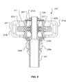
Figure 8 is an exploded view of the rotor hub of the rotorcraft, according to an example embodiment; and -
Figure 9 is a schematic view of a computer system, according to example embodiment. - Illustrative embodiments of the apparatus are described below. In the interest of clarity, all features of an actual implementation may not be described in this specification. It will of course be appreciated that in the development of any such actual embodiment, numerous implementation-specific decisions must be made to achieve the developer's specific goals, such as compliance with system-related and business-related constraints, which will vary from one implementation to another. Moreover, it will be appreciated that such a development effort might be complex and time-consuming but would nevertheless be a routine undertaking for those of ordinary skill in the art having the benefit of this disclosure.
- In the specification, reference may be made to the spatial relationships between various components and to the spatial orientation of various aspects of components as the devices are depicted in the attached drawings. However, as will be recognized by those skilled in the art after a complete reading of the present application, the devices, members, apparatuses, etc. described herein may be positioned in any desired orientation. Thus, the use of terms such as "above," "below," "upper," "lower," or other like terms to describe a spatial relationship between various components or to describe the spatial orientation of aspects of such components should be understood to describe a relative relationship between the components or a spatial orientation of aspects of such components, respectively, as the device described herein may be oriented in any desired direction.
- Referring now to
Figure 1 in the drawings, arotorcraft 101 is illustrated. Rotorcraft 101 has arotor hub 103 with a plurality ofrotor blades 105. The pitch of eachrotor blade 105 can be manipulated in order to selectively control direction, thrust, and lift ofrotorcraft 101. Rotorcraft 101 can further include afuselage 107,anti-torque system 109, and anempennage 111. It should be appreciated thatrotorcraft 101 is merely illustrative of an aircraft for with which the embodiments of the present disclosure can be utilized. - During operation of
rotorcraft 101,rotor hub 103 can experience various vibration types throughout the flight spectrum. One vibration type is vibration resulting from a flapping of the rotor blades. The rotor blade flapping can be the result of unequal lifting forces being exerted on the rotor blades, such as high speed forward flight, which can cause the rotor hub to teeter. Another vibration type is a vibration resulting from a "pin wheeling" action. Pin wheeling can be the result of a tilting of the rotor hub which can cause the rotor mast to be pulled in a direction perpendicular to the rotor mast axis. The perpendicular force then has a tendency to travel around the azimuth of the mast. As the rotor hub rotates, the pulling of the rotor mast turns into a whirling effect as the rotor mast is continuously pulled. Another vibration mode can develop when the dynamics of the rotor system combine to create a force which oscillates on a single axis perpendicular to the mast, such as axis 241 (shown at least inFigure 7 ), such an oscillation can be referred to as "hub shift." Another vibration type is a vertical vibration or "chucking" from vertical component vibratory loads generated in the flight regime. - Referring now also to
Figures 2-8 ,rotor hub 103 is illustrated in further detail. Therotor hub 103 incorporates structural features which allow the torque fromrotor mast 201 to be transferred to ayoke 211 while also being compliant in a direction for vibration attenuation. Further,rotor hub 103 incorporates actuators actively to counter or attenuate vibrations that may result from one or more vibration inducing vibratory modes, such as rotor blade flapping, hub whirling, hub shifting, and vertical oscillations. One object of the embodiments in the present disclosure is to substantially eliminate the oscillatory vibrations in therotor hub 103 to prevent the oscillatory vibrations from being transmitted throughmast 201 to the body ofrotorcraft 101. -
Rotor hub 103 can include a hub member oryoke 211 coupled between amast 201 and a plurality of rotor blades, such as rotor blades 105 (shown inFigure 1 ). In the example embodiment,yoke 211 includes acentral portion 215, anupper portion 217, alower portion 219, and loopedarms 213a-213d.Central portion 215 centrally connectsupper portion 217 andlower portion 219. Each loopedarm 213a-213d connectsupper portion 219 andlower portion 219 and a discreet extension where each rotor blade, such as arotor blade 105, is coupled thereto. In an example embodiment, eachrotor blade 105 has a rotor blade grip that is coupled to one of loopedarms 213a-213d via one or more bearings. It should be fully appreciated that the exact configuration ofyoke 211 and the attachment ofrotor blades 105 thereto is implementation specific. Further,yoke 211 is illustrated for the usage of four rotor blades; however, it should be appreciated that any reasonable number of rotor blades can be utilized androtor hub 103 be adapted accordingly. Additionally, the hub/yoke to blade attachment configuration can be vertically arranged (as shown), horizontally arranged, arranged in a bolted joint configuration, arranged in pass through yoke/snubber configuration, or any other implementation specific arrangement that still allows for the functionality of the vibration control system described herein. - Mast 201 includes a splined
portion 225 that mates with asplined portion 227 of apivot member 229. The splined connection ofpivot member 229 andmast 201 allows for a limited amount of sliding ofpivot member 229 along amast axis 231, but also rigid transfer of torque betweenmast 201 andpivot member 229.Pivot member 229 has a rigid firstcylindrical extension 235 and rigid secondcylindrical extension 237 each extending in opposite directions along anaxis 239. Cylindricalelastomeric members cylindrical extension 235 and secondcylindrical extension 237, respectively, and cylindrical openings of agimbal ring 233. Gimbalring 233 is illustrated as having anupper half 233a and alower half 233b that collectively formgimbal ring 233. Cylindricalelastomeric members axis 239. -
Central portion 215 ofyoke 211 includes a firstcylindrical post 243 and a secondcylindrical post 245, each extending in opposite directions along anaxis 241. Cylindricalelastomeric members cylindrical post 243 and a secondcylindrical post 245, respectively, and cylindrical openings ofgimbal ring 233. Cylindricalelastomeric members axis 241. - The example embodiment, the torque from
rotor mast 201 is transferred to thepivot member 229, then togimbal ring 233 viaextensions yoke 211 viaposts -
Rotor hub 103 can also include anupper cap 203 and anelastomeric member 205 adjacent to an upper surface ofyoke 211 to keepyoke 211 to place an upper vertical onyoke 211 alongmast 201. Similarly, alower cap 221 and anelastomeric member 223 can be located adjacent to a lower surface ofyoke 211 to place a lower vertical limitation onyoke 211 alongmast 201. -
Rotor hub 103 can includeactuators 207a-207d that are radially oriented and located in a plane perpendicular to therotor mast axis 231.Actuators axis 241 that bear against opposing surfaces ofpivot member 229.Actuators mast 201 in a direction alongaxis 241. The actuation of actuators 207a and 207c can cause a displacement ofyoke 211 relative tomast 201 alongaxis 241, which can cause a shearing deflection ofelastomeric members actuators axis 239 that bear against opposing surfaces offirst extension 235 andsecond extension 237 ofpivot member 229.Actuators mast 201 in a direction alongaxis 239. The actuation ofactuators yoke 211 relative tomast 201 alongaxis 239, which can cause a shearing deflection ofelastomeric members - During an actuation of actuators 207a and 207c, the
pivot member 229 will translate relative toyoke 211 alongaxis 241, thus causing the piston rods associated withactuators first extension 235 andsecond extension 237 ofpivot member 229. Similarly, during actuation ofactuators pivot member 229 will translate relative toyoke 211 alongaxis 239, thus causing the piston rods associated withactuators pivot member 229. It should be appreciated that actuators 207a-207d can be any implementation specific type of actuator, such as electric, hydraulic, pneumatic, piezoelectric, to name a few examples. -
Rotor hub 103 can also includeactuators 209a-209d that are coupled betweenrotor mast 201 andlower portion 219 ofyoke 211. Each actuator 209a-209d is oriented substantially vertical but also slightly cantilevered out toward a respective loopedarm 213a-213d where arespective rotor blade 105 is coupled thereto. In the example embodiment,actuator 209a is aligned with loopedarm 213a,actuator 209b is aligned with loopedarm 213b,actuator 209c is aligned with loopedarm 213c, andactuator 209d is aligned with loopedarm 213d. Each actuator 209a-209d is configured to selectively impart a force uponyoke 211, which can cause a small translation ofyoke 211 relative tomast 201. It should be appreciated that actuators 209a-209d can be any implementation specific type of actuator, such as electric, hydraulic, pneumatic, piezoelectric, to name a few examples. - The force generated by
actuators 207a-207d and 209a-209d has a powerful but small stroke distance, such as approximately .050 of an inch. Considering the small stroke distance, the force may be similar to a bump. - Actuators 209a-209d and
actuators 207a-207d are configured either alone or in combination to attenuate one or more types of vibration that may arise during operation of therotorcraft 101. A control system, such ascontrol system 247, is in communication with vibration sensors, such as accelerometers, for detecting vibration. Further,control system 247 can include a processor for analyzing the source and direction of the vibration. Thecontrol system 247 is configured to selectively command actuators 209a-209d andactuators 207a-207d. - During a pin wheeling vibration, or an in-plane whirling effect between the
mast 201 andyoke 211,control system 247 is configured to selectively actuate actuators 207a-207d to counter the whirling and misalignment between themast axis 231 and the center ofyoke 211. Actuators 207a-207d can selectively pushmast 201 in directions alongaxes mast 201 andyoke 211 and attenuating the vibration stemming therefrom. - During a hub shifting vibration between the
mast 201 andyoke 211,control system 247 is configured to selectively actuate actuators 207a-207d to counter the hub shifting. Actuators 207a-207d can selectively pushmast 201 substantially in a single direction, such as a direction along one ofaxes mast 201 andyoke 211 and attenuating the vibration stemming therefrom. - During a flapping variation of
rotor blades 105 associated with loopedarms 213a-213d ofyoke 211, flapping vibration can be generated. An illustrative flapping direction is illustrated inFigure 6 as flappingdirection 249, which corresponds with loopedarm 213b. In order to attenuate any vibration resulting from rotor blade flapping, any ofactuators 209a-209d can be selectively actuated to counter the flapping load or deflection. For example, if a rotor blade were to flap up, then the actuator associated with that rotor blade can be actuated to pull on the particular looped arm associated with that particular rotor blade. Thus each of actuators 209a-209d can be individually actuated once or more within a single revolution to attenuated vibration from rotor blade flapping. - During a vertical vibration or "chucking" from vertical component vibratory loads, actuators 209a-209d can be collectively actuated to counter the vertical oscillations.
Elastomeric members mast axis 231 and onspline 225. To counter a single upward vertical oscillation ofyoke 211, then theactuators 209a-209d collectively pullyoke 211 downward, for example. - Referring now also to
Figure 9 , acomputer system 901 is schematically illustrated.System 901 can be configured for performing one or more functions with regard to the operation ofrotor hub 103. More specifically,system 901 can be configured for performing one or more functions with regard to the operation ofcontrol system 247. Further, any processing and analysis can be partly or fully performed bycomputer system 901.Computer system 901 can be partly or fully integrated with other computer systems. In one example,computer system 901 is integrated with the flight control computer inrotorcraft 101. - The
system 901 can include an input/output (I/O)interface 903, ananalysis engine 905, and adatabase 907. Alternative embodiments can combine or distribute the input/output (I/O)interface 903,analysis engine 905, anddatabase 907, as desired. Embodiments of thesystem 901 can include one or more computers that include one or more processors and memories configured for performing tasks described herein. This can include, for example, a computer having a central processing unit (CPU) and non-volatile memory that stores software instructions for instructing the CPU to perform at least some of the tasks described herein. This can also include, for example, two or more computers that are in communication via a computer network, where one or more of the computers include a CPU and non-volatile memory, and one or more of the computer's non-volatile memory stores software instructions for instructing any of the CPU(s) to perform any of the tasks described herein. Thus, while the exemplary embodiment is described in terms of a discrete machine, it should be appreciated that this description is non-limiting, and that the present description applies equally to numerous other arrangements involving one or more machines performing tasks distributed in any way among the one or more machines. It should also be appreciated that such machines need not be dedicated to performing tasks described herein, but instead can be multi-purpose machines, for example computer workstations, that are suitable for also performing other tasks. - The I/
O interface 903 can provide a communication link between external users, systems, and data sources and components of thesystem 901. The I/O interface 903 can be configured for allowing one or more users to input information to thesystem 901 via any known input device. Examples can include a keyboard, mouse, touch screen, and/or any other desired input device. The I/O interface 903 can be configured for allowing one or more users to receive information output from thesystem 901 via any known output device. Examples can include a display monitor, a printer, and/or any other desired output device. The I/O interface 903 can be configured for allowing other systems to communicate with thesystem 901. For example, the I/O interface 903 can allow one or more remote computer(s) to access information, input information, and/or remotely instruct thesystem 901 to perform one or more of the tasks described herein. The I/O interface 903 can be configured for allowing communication with one or more remote data sources. For example, the I/O interface 903 can allow one or more remote data source(s) to access information, input information, and/or remotely instruct thesystem 901 to perform one or more of the tasks described herein. - The
database 907 can provide persistent data storage forsystem 901. While the term "database" is primarily used, a memory or other suitable data storage arrangement may provide the functionality of thedatabase 907. In alternative embodiments, thedatabase 907 can be integral to or separate from thesystem 901 and can operate on one or more computers. Thedatabase 907 preferably provides non-volatile data storage for any information suitable to support the operation of actuators 207a-207d and 209a-209d, including various types of data. Theanalysis engine 905 can include various combinations of one or more processors, memories, and software components. - The particular embodiments disclosed above are illustrative only, as the apparatus may be modified and practiced in different but equivalent manners apparent to those skilled in the art having the benefit of the teachings herein. Modifications, additions, or omissions may be made to the apparatuses described herein without departing from the scope of the invention. The components of the apparatus may be integrated or separated. Moreover, the operations of the apparatus may be performed by more, fewer, or other components.
- Furthermore, no limitations are intended to the details of construction or design herein shown, other than as described in the claims below. It is therefore evident that the particular embodiments disclosed above may be altered or modified and all such variations are considered within the scope and spirit of the application. Accordingly, the protection sought herein is as set forth in the claims below.
- To aid the Patent Office, and any readers of any patent issued on this application in interpreting the claims appended hereto, applicants wish to note that they do not intend any of the appended claims to invoke paragraph 6 of 35 U.S.C. § 112 as it exists on the date of filing hereof unless the words "means for" or "step for" are explicitly used in the particular claim.
Claims (15)
- A rotor hub for a rotary aircraft, the rotor hub comprising:a rotor mast;a yoke;a plurality of actuators coupled between the rotor mast and the yoke, the plurality of actuators being configured to selectively impart a force.
- The rotor hub according to claim 1, further comprising:a plurality of rotor blades;wherein each of the plurality of actuators are coupled to an arm of the yoke, each arm defining a location of a rotor blade.
- The rotor hub according to claim 1 or claim 2, further comprising:a compliant elastomeric member configured to compress due to a translation of the yoke along an axis of the rotor mast due to an actuation of the plurality of actuators.
- A rotor hub for a rotorcraft, the rotor hub comprising:a yoke;a mast;a first radial actuator; anda second radial actuator;wherein the first radial actuator and the second radial actuator each have a piston configured to impart a translation of the yoke relative to the mast.
- The rotor hub according to claim 4, wherein the first radial actuator and the second radial actuator line along a plane perpendicular an axis of the mast.
- The rotor hub according to claim 1 or claim 2 or claim 3, further comprising:a pivot member splined to the rotor mast, the pivot member having a first extension and a second extension that form a first axis; anda first post and second post extending from the yoke and forming a second axis;
ora rotor hub according to claim 4 or claim 5 further comprising:a pivot member splined to the mast, the pivot member having a first extension and a second extension that form a first axis; anda first post and second post extending from the yoke and forming a second axis. - The rotor hub according to claim 6 as it depends from any preceding claim, further comprising:a gimbal ring that houses the first post, the second post, the first extension and the second extension.
- The rotor hub according to claim 7, further comprising:an elastomeric material between each of the first post, the second post, the first extension, the second extension and the gimbal ring.
- The rotor hub according to claim 8, further comprising:a first radial actuator; anda second radial actuator;wherein the first radial actuator and the second radial actuator each have a piston configured to impart a force on the pivot member.
- The rotor hub according to claim 9, wherein either of the first radial actuator and the second radial actuator can cause a translation of the yoke relative to the mast along an axis defined by the first radial actuator and the second radial actuator.
- The rotor hub according to claim 8 or claim 9 or claim 10, further comprising:a third radial actuator; anda fourth radial actuator;wherein the third radial actuator and the fourth radial actuator each have a piston configured to impart a force on the pivot member; orthe rotor hub of claim 4 or claim 5, or any preceding claim dependent directly or indirectly from claim 4 or claim 5, comprising:a rotor mast;a yoke;a plurality of actuators coupled between the rotor mast and the yoke, the plurality of actuators being configured to selectively impart a force.
- The rotor hub according to claim 11, wherein either of the third radial actuator and the fourth radial actuator can cause a translation of the yoke relative to the mast along an axis defined by the third radial actuator and the fourth radial actuator.
- The rotor hub according to claim 1 or any preceding claim, further comprising:a control system configured to analyze vibration measurement and command the plurality of actuators.
- The rotor hub according to claim 11, wherein the translation is along an axis formed by the third radial actuator and the fourth radial actuator.
- A rotary aircraft having a rotor hub in accordance with any of claims 1 to 14.
Applications Claiming Priority (1)
| Application Number | Priority Date | Filing Date | Title |
|---|---|---|---|
| US14/135,941 US9896199B2 (en) | 2013-12-20 | 2013-12-20 | Rotor hub for a rotorcraft |
Publications (2)
| Publication Number | Publication Date |
|---|---|
| EP2886455A1 true EP2886455A1 (en) | 2015-06-24 |
| EP2886455B1 EP2886455B1 (en) | 2015-10-28 |
Family
ID=51162610
Family Applications (1)
| Application Number | Title | Priority Date | Filing Date |
|---|---|---|---|
| EP14176752.5A Active EP2886455B1 (en) | 2013-12-20 | 2014-07-11 | Rotor hub for a rotorcraft |
Country Status (2)
| Country | Link |
|---|---|
| US (1) | US9896199B2 (en) |
| EP (1) | EP2886455B1 (en) |
Cited By (1)
| Publication number | Priority date | Publication date | Assignee | Title |
|---|---|---|---|---|
| EP3323719A1 (en) * | 2016-11-22 | 2018-05-23 | Bell Helicopter Textron Inc. | Axial springs for rotor hub assembly |
Families Citing this family (4)
| Publication number | Priority date | Publication date | Assignee | Title |
|---|---|---|---|---|
| WO2016081681A1 (en) * | 2014-11-19 | 2016-05-26 | Sikorsky Aircraft Corporation | Method of balancing a main rotor hub |
| US10239610B2 (en) * | 2015-03-10 | 2019-03-26 | Bell Helicopter Textron Inc. | Compact linear hydraulic actuator |
| KR101627680B1 (en) * | 2015-11-05 | 2016-06-07 | 남양우 | Airplane structure |
| US11427315B2 (en) * | 2019-06-26 | 2022-08-30 | Textron Innovations Inc. | Rotor blade control system |
Citations (5)
| Publication number | Priority date | Publication date | Assignee | Title |
|---|---|---|---|---|
| US4073600A (en) * | 1976-06-14 | 1978-02-14 | William Gallagher | Damping mechanism for the rotor hub of a helicopter for ground resonance and waddle and its combination with the rotor |
| EP0521759A1 (en) * | 1991-07-02 | 1993-01-07 | Eurocopter France | Method and device to reduce the divergent oscillations of a helicopter fuselage |
| US5647726A (en) * | 1996-02-15 | 1997-07-15 | Bell Helicopter Textron Inc. | Rotor system vibration absorber |
| US20070215749A1 (en) * | 2006-03-17 | 2007-09-20 | Sikorsky Aircraft Corporation | Rotor assemblies having automatic blade folding systems |
| EP2796368A1 (en) * | 2013-04-22 | 2014-10-29 | Sikorsky Aircraft Corporation | Integration of rotary electrical actuator for swashplateless individual blade control |
Family Cites Families (7)
| Publication number | Priority date | Publication date | Assignee | Title |
|---|---|---|---|---|
| US2402349A (en) * | 1943-02-27 | 1946-06-18 | United Aircraft Corp | Adjustable rotor |
| US2529635A (en) * | 1945-10-31 | 1950-11-14 | United Aircraft Corp | Helicopter rotor control mechanism |
| US3176774A (en) * | 1963-07-24 | 1965-04-06 | William V Krinsky | Helicopter drive control |
| ITTO20010101A1 (en) * | 2001-02-02 | 2002-08-02 | Agusta Spa | ROTOR WITH HOMOCINETIC TRANSMISSION UNIT FOR AN AIRCRAFT. |
| CN101107163A (en) * | 2005-11-30 | 2008-01-16 | 贝尔直升机泰克斯特龙公司 | rotorcraft torque converter |
| US8038539B2 (en) * | 2008-01-04 | 2011-10-18 | Bell Helicopter Textron Inc. | Constant-velocity joint with torque-combining differential |
| US8038394B2 (en) * | 2008-01-16 | 2011-10-18 | Sikorsky Aircraft Corporation | System and method of damping a 1P motion |
-
2013
- 2013-12-20 US US14/135,941 patent/US9896199B2/en active Active
-
2014
- 2014-07-11 EP EP14176752.5A patent/EP2886455B1/en active Active
Patent Citations (5)
| Publication number | Priority date | Publication date | Assignee | Title |
|---|---|---|---|---|
| US4073600A (en) * | 1976-06-14 | 1978-02-14 | William Gallagher | Damping mechanism for the rotor hub of a helicopter for ground resonance and waddle and its combination with the rotor |
| EP0521759A1 (en) * | 1991-07-02 | 1993-01-07 | Eurocopter France | Method and device to reduce the divergent oscillations of a helicopter fuselage |
| US5647726A (en) * | 1996-02-15 | 1997-07-15 | Bell Helicopter Textron Inc. | Rotor system vibration absorber |
| US20070215749A1 (en) * | 2006-03-17 | 2007-09-20 | Sikorsky Aircraft Corporation | Rotor assemblies having automatic blade folding systems |
| EP2796368A1 (en) * | 2013-04-22 | 2014-10-29 | Sikorsky Aircraft Corporation | Integration of rotary electrical actuator for swashplateless individual blade control |
Cited By (1)
| Publication number | Priority date | Publication date | Assignee | Title |
|---|---|---|---|---|
| EP3323719A1 (en) * | 2016-11-22 | 2018-05-23 | Bell Helicopter Textron Inc. | Axial springs for rotor hub assembly |
Also Published As
| Publication number | Publication date |
|---|---|
| US20150175259A1 (en) | 2015-06-25 |
| EP2886455B1 (en) | 2015-10-28 |
| US9896199B2 (en) | 2018-02-20 |
Similar Documents
| Publication | Publication Date | Title |
|---|---|---|
| US10814963B2 (en) | Active vibration control system with non-concentric revolving masses | |
| US9896199B2 (en) | Rotor hub for a rotorcraft | |
| EP2076436B1 (en) | Dual higher harmonic control (hhc) for a counter-rotating, coaxial rotor system | |
| EP2615028B1 (en) | Rotorcraft vibration suppression system in a four corner pylon mount configuration | |
| US20150125300A1 (en) | Rotor hub for a rotorcraft | |
| EP3150489A1 (en) | Unified control of multiple active systems for helicopter vibration supression | |
| US8622375B2 (en) | Dual frequency damper for an aircraft | |
| US10457380B2 (en) | Articulated rotor systems with pitch independent damping | |
| EP0007317B1 (en) | Helicopter with stabilator detuned in antisymmetric vibration modes from main rotor wake excitation frequency | |
| EP3431392A1 (en) | Higher harmonic control augmented with active vibration control | |
| EP0790180A1 (en) | Rotor system vibration absorber | |
| US10745116B2 (en) | Anti-vibration load generating aircraft actuation system | |
| EP2982597A1 (en) | Tail spar spring | |
| US9765825B2 (en) | Rotor hub damper for a rotorcraft | |
| US20150210381A1 (en) | Pitch feedback control splitting for helicopters with redundant actuators | |
| US8888037B2 (en) | Antivibration suspension means for a tie bar of an aircraft power transmission gearbox, an antivibration suspension device, and an aircraft | |
| Kakaley et al. | An offset hub active vibration control system for mitigating helicopter vibrations during power loss: Simulation and experimental demonstration | |
| US8636472B2 (en) | Blade damper, and a rotor fitted with such a damper | |
| US20120269630A1 (en) | Rotor damper device, and an associated rotor and aircraft | |
| US20250091713A1 (en) | Varying a pitch of a tiltrotor | |
| US11203418B2 (en) | Mount systems for pylon assemblies with coaxial rotors | |
| EP3560831A1 (en) | Articulated rotor systems with blade-to-blade damping | |
| Bang et al. | Active Airframe vibration control study using a small-scale model for lift-offset compound helicopter | |
| EP1334289B1 (en) | Method and apparatus for improved vibration isolation | |
| US9114875B2 (en) | Lead lag damper for helicopter rotor unit |
Legal Events
| Date | Code | Title | Description |
|---|---|---|---|
| PUAI | Public reference made under article 153(3) epc to a published international application that has entered the european phase |
Free format text: ORIGINAL CODE: 0009012 |
|
| 17P | Request for examination filed |
Effective date: 20140711 |
|
| AK | Designated contracting states |
Kind code of ref document: A1 Designated state(s): AL AT BE BG CH CY CZ DE DK EE ES FI FR GB GR HR HU IE IS IT LI LT LU LV MC MK MT NL NO PL PT RO RS SE SI SK SM TR |
|
| AX | Request for extension of the european patent |
Extension state: BA ME |
|
| GRAP | Despatch of communication of intention to grant a patent |
Free format text: ORIGINAL CODE: EPIDOSNIGR1 |
|
| INTG | Intention to grant announced |
Effective date: 20150810 |
|
| RIN1 | Information on inventor provided before grant (corrected) |
Inventor name: SUTTON, DREW Inventor name: FOSKEY, CHRISTOPHER Inventor name: STAMPS, FRANK B. |
|
| GRAS | Grant fee paid |
Free format text: ORIGINAL CODE: EPIDOSNIGR3 |
|
| GRAA | (expected) grant |
Free format text: ORIGINAL CODE: 0009210 |
|
| AK | Designated contracting states |
Kind code of ref document: B1 Designated state(s): AL AT BE BG CH CY CZ DE DK EE ES FI FR GB GR HR HU IE IS IT LI LT LU LV MC MK MT NL NO PL PT RO RS SE SI SK SM TR |
|
| REG | Reference to a national code |
Ref country code: GB Ref legal event code: FG4D |
|
| REG | Reference to a national code |
Ref country code: CH Ref legal event code: EP |
|
| REG | Reference to a national code |
Ref country code: AT Ref legal event code: REF Ref document number: 757777 Country of ref document: AT Kind code of ref document: T Effective date: 20151115 |
|
| REG | Reference to a national code |
Ref country code: IE Ref legal event code: FG4D |
|
| REG | Reference to a national code |
Ref country code: DE Ref legal event code: R096 Ref document number: 602014000389 Country of ref document: DE |
|
| REG | Reference to a national code |
Ref country code: LT Ref legal event code: MG4D |
|
| REG | Reference to a national code |
Ref country code: NL Ref legal event code: MP Effective date: 20151028 |
|
| REG | Reference to a national code |
Ref country code: AT Ref legal event code: MK05 Ref document number: 757777 Country of ref document: AT Kind code of ref document: T Effective date: 20151028 |
|
| PG25 | Lapsed in a contracting state [announced via postgrant information from national office to epo] |
Ref country code: HR Free format text: LAPSE BECAUSE OF FAILURE TO SUBMIT A TRANSLATION OF THE DESCRIPTION OR TO PAY THE FEE WITHIN THE PRESCRIBED TIME-LIMIT Effective date: 20151028 Ref country code: NL Free format text: LAPSE BECAUSE OF FAILURE TO SUBMIT A TRANSLATION OF THE DESCRIPTION OR TO PAY THE FEE WITHIN THE PRESCRIBED TIME-LIMIT Effective date: 20151028 Ref country code: ES Free format text: LAPSE BECAUSE OF FAILURE TO SUBMIT A TRANSLATION OF THE DESCRIPTION OR TO PAY THE FEE WITHIN THE PRESCRIBED TIME-LIMIT Effective date: 20151028 Ref country code: LT Free format text: LAPSE BECAUSE OF FAILURE TO SUBMIT A TRANSLATION OF THE DESCRIPTION OR TO PAY THE FEE WITHIN THE PRESCRIBED TIME-LIMIT Effective date: 20151028 Ref country code: NO Free format text: LAPSE BECAUSE OF FAILURE TO SUBMIT A TRANSLATION OF THE DESCRIPTION OR TO PAY THE FEE WITHIN THE PRESCRIBED TIME-LIMIT Effective date: 20160128 Ref country code: IS Free format text: LAPSE BECAUSE OF FAILURE TO SUBMIT A TRANSLATION OF THE DESCRIPTION OR TO PAY THE FEE WITHIN THE PRESCRIBED TIME-LIMIT Effective date: 20160228 |
|
| PG25 | Lapsed in a contracting state [announced via postgrant information from national office to epo] |
Ref country code: FI Free format text: LAPSE BECAUSE OF FAILURE TO SUBMIT A TRANSLATION OF THE DESCRIPTION OR TO PAY THE FEE WITHIN THE PRESCRIBED TIME-LIMIT Effective date: 20151028 Ref country code: AT Free format text: LAPSE BECAUSE OF FAILURE TO SUBMIT A TRANSLATION OF THE DESCRIPTION OR TO PAY THE FEE WITHIN THE PRESCRIBED TIME-LIMIT Effective date: 20151028 Ref country code: PL Free format text: LAPSE BECAUSE OF FAILURE TO SUBMIT A TRANSLATION OF THE DESCRIPTION OR TO PAY THE FEE WITHIN THE PRESCRIBED TIME-LIMIT Effective date: 20151028 Ref country code: SE Free format text: LAPSE BECAUSE OF FAILURE TO SUBMIT A TRANSLATION OF THE DESCRIPTION OR TO PAY THE FEE WITHIN THE PRESCRIBED TIME-LIMIT Effective date: 20151028 Ref country code: PT Free format text: LAPSE BECAUSE OF FAILURE TO SUBMIT A TRANSLATION OF THE DESCRIPTION OR TO PAY THE FEE WITHIN THE PRESCRIBED TIME-LIMIT Effective date: 20160229 Ref country code: RS Free format text: LAPSE BECAUSE OF FAILURE TO SUBMIT A TRANSLATION OF THE DESCRIPTION OR TO PAY THE FEE WITHIN THE PRESCRIBED TIME-LIMIT Effective date: 20151028 Ref country code: GR Free format text: LAPSE BECAUSE OF FAILURE TO SUBMIT A TRANSLATION OF THE DESCRIPTION OR TO PAY THE FEE WITHIN THE PRESCRIBED TIME-LIMIT Effective date: 20160129 Ref country code: LV Free format text: LAPSE BECAUSE OF FAILURE TO SUBMIT A TRANSLATION OF THE DESCRIPTION OR TO PAY THE FEE WITHIN THE PRESCRIBED TIME-LIMIT Effective date: 20151028 |
|
| REG | Reference to a national code |
Ref country code: FR Ref legal event code: PLFP Year of fee payment: 3 |
|
| PG25 | Lapsed in a contracting state [announced via postgrant information from national office to epo] |
Ref country code: CZ Free format text: LAPSE BECAUSE OF FAILURE TO SUBMIT A TRANSLATION OF THE DESCRIPTION OR TO PAY THE FEE WITHIN THE PRESCRIBED TIME-LIMIT Effective date: 20151028 |
|
| REG | Reference to a national code |
Ref country code: DE Ref legal event code: R097 Ref document number: 602014000389 Country of ref document: DE |
|
| PG25 | Lapsed in a contracting state [announced via postgrant information from national office to epo] |
Ref country code: RO Free format text: LAPSE BECAUSE OF FAILURE TO SUBMIT A TRANSLATION OF THE DESCRIPTION OR TO PAY THE FEE WITHIN THE PRESCRIBED TIME-LIMIT Effective date: 20151028 Ref country code: SK Free format text: LAPSE BECAUSE OF FAILURE TO SUBMIT A TRANSLATION OF THE DESCRIPTION OR TO PAY THE FEE WITHIN THE PRESCRIBED TIME-LIMIT Effective date: 20151028 Ref country code: EE Free format text: LAPSE BECAUSE OF FAILURE TO SUBMIT A TRANSLATION OF THE DESCRIPTION OR TO PAY THE FEE WITHIN THE PRESCRIBED TIME-LIMIT Effective date: 20151028 Ref country code: DK Free format text: LAPSE BECAUSE OF FAILURE TO SUBMIT A TRANSLATION OF THE DESCRIPTION OR TO PAY THE FEE WITHIN THE PRESCRIBED TIME-LIMIT Effective date: 20151028 Ref country code: SM Free format text: LAPSE BECAUSE OF FAILURE TO SUBMIT A TRANSLATION OF THE DESCRIPTION OR TO PAY THE FEE WITHIN THE PRESCRIBED TIME-LIMIT Effective date: 20151028 |
|
| PLBE | No opposition filed within time limit |
Free format text: ORIGINAL CODE: 0009261 |
|
| STAA | Information on the status of an ep patent application or granted ep patent |
Free format text: STATUS: NO OPPOSITION FILED WITHIN TIME LIMIT |
|
| 26N | No opposition filed |
Effective date: 20160729 |
|
| PG25 | Lapsed in a contracting state [announced via postgrant information from national office to epo] |
Ref country code: SI Free format text: LAPSE BECAUSE OF FAILURE TO SUBMIT A TRANSLATION OF THE DESCRIPTION OR TO PAY THE FEE WITHIN THE PRESCRIBED TIME-LIMIT Effective date: 20151028 |
|
| PG25 | Lapsed in a contracting state [announced via postgrant information from national office to epo] |
Ref country code: BE Free format text: LAPSE BECAUSE OF FAILURE TO SUBMIT A TRANSLATION OF THE DESCRIPTION OR TO PAY THE FEE WITHIN THE PRESCRIBED TIME-LIMIT Effective date: 20151028 |
|
| PG25 | Lapsed in a contracting state [announced via postgrant information from national office to epo] |
Ref country code: MC Free format text: LAPSE BECAUSE OF FAILURE TO SUBMIT A TRANSLATION OF THE DESCRIPTION OR TO PAY THE FEE WITHIN THE PRESCRIBED TIME-LIMIT Effective date: 20151028 |
|
| REG | Reference to a national code |
Ref country code: IE Ref legal event code: MM4A |
|
| REG | Reference to a national code |
Ref country code: FR Ref legal event code: PLFP Year of fee payment: 4 |
|
| PG25 | Lapsed in a contracting state [announced via postgrant information from national office to epo] |
Ref country code: IE Free format text: LAPSE BECAUSE OF NON-PAYMENT OF DUE FEES Effective date: 20160711 |
|
| PG25 | Lapsed in a contracting state [announced via postgrant information from national office to epo] |
Ref country code: LU Free format text: LAPSE BECAUSE OF NON-PAYMENT OF DUE FEES Effective date: 20160711 |
|
| REG | Reference to a national code |
Ref country code: CH Ref legal event code: PL |
|
| PG25 | Lapsed in a contracting state [announced via postgrant information from national office to epo] |
Ref country code: CH Free format text: LAPSE BECAUSE OF NON-PAYMENT OF DUE FEES Effective date: 20170731 Ref country code: LI Free format text: LAPSE BECAUSE OF NON-PAYMENT OF DUE FEES Effective date: 20170731 |
|
| PG25 | Lapsed in a contracting state [announced via postgrant information from national office to epo] |
Ref country code: HU Free format text: LAPSE BECAUSE OF FAILURE TO SUBMIT A TRANSLATION OF THE DESCRIPTION OR TO PAY THE FEE WITHIN THE PRESCRIBED TIME-LIMIT; INVALID AB INITIO Effective date: 20140711 |
|
| PG25 | Lapsed in a contracting state [announced via postgrant information from national office to epo] |
Ref country code: MT Free format text: LAPSE BECAUSE OF NON-PAYMENT OF DUE FEES Effective date: 20160731 Ref country code: MK Free format text: LAPSE BECAUSE OF FAILURE TO SUBMIT A TRANSLATION OF THE DESCRIPTION OR TO PAY THE FEE WITHIN THE PRESCRIBED TIME-LIMIT Effective date: 20151028 Ref country code: CY Free format text: LAPSE BECAUSE OF FAILURE TO SUBMIT A TRANSLATION OF THE DESCRIPTION OR TO PAY THE FEE WITHIN THE PRESCRIBED TIME-LIMIT Effective date: 20151028 |
|
| REG | Reference to a national code |
Ref country code: FR Ref legal event code: PLFP Year of fee payment: 5 |
|
| PG25 | Lapsed in a contracting state [announced via postgrant information from national office to epo] |
Ref country code: BG Free format text: LAPSE BECAUSE OF FAILURE TO SUBMIT A TRANSLATION OF THE DESCRIPTION OR TO PAY THE FEE WITHIN THE PRESCRIBED TIME-LIMIT Effective date: 20151028 |
|
| PG25 | Lapsed in a contracting state [announced via postgrant information from national office to epo] |
Ref country code: TR Free format text: LAPSE BECAUSE OF FAILURE TO SUBMIT A TRANSLATION OF THE DESCRIPTION OR TO PAY THE FEE WITHIN THE PRESCRIBED TIME-LIMIT Effective date: 20151028 Ref country code: AL Free format text: LAPSE BECAUSE OF FAILURE TO SUBMIT A TRANSLATION OF THE DESCRIPTION OR TO PAY THE FEE WITHIN THE PRESCRIBED TIME-LIMIT Effective date: 20151028 |
|
| PGFP | Annual fee paid to national office [announced via postgrant information from national office to epo] |
Ref country code: IT Payment date: 20210721 Year of fee payment: 8 |
|
| PGFP | Annual fee paid to national office [announced via postgrant information from national office to epo] |
Ref country code: GB Payment date: 20210727 Year of fee payment: 8 |
|
| GBPC | Gb: european patent ceased through non-payment of renewal fee |
Effective date: 20220711 |
|
| PG25 | Lapsed in a contracting state [announced via postgrant information from national office to epo] |
Ref country code: GB Free format text: LAPSE BECAUSE OF NON-PAYMENT OF DUE FEES Effective date: 20220711 |
|
| P01 | Opt-out of the competence of the unified patent court (upc) registered |
Effective date: 20230602 |
|
| PG25 | Lapsed in a contracting state [announced via postgrant information from national office to epo] |
Ref country code: IT Free format text: LAPSE BECAUSE OF NON-PAYMENT OF DUE FEES Effective date: 20220711 |
|
| PGFP | Annual fee paid to national office [announced via postgrant information from national office to epo] |
Ref country code: DE Payment date: 20250729 Year of fee payment: 12 |
|
| PGFP | Annual fee paid to national office [announced via postgrant information from national office to epo] |
Ref country code: FR Payment date: 20250725 Year of fee payment: 12 |