EP2886443A1 - Installation device - Google Patents
Installation device Download PDFInfo
- Publication number
- EP2886443A1 EP2886443A1 EP13198539.2A EP13198539A EP2886443A1 EP 2886443 A1 EP2886443 A1 EP 2886443A1 EP 13198539 A EP13198539 A EP 13198539A EP 2886443 A1 EP2886443 A1 EP 2886443A1
- Authority
- EP
- European Patent Office
- Prior art keywords
- main beam
- beam section
- lining panel
- installation device
- movable
- Prior art date
- Legal status (The legal status is an assumption and is not a legal conclusion. Google has not performed a legal analysis and makes no representation as to the accuracy of the status listed.)
- Granted
Links
Images









Classifications
-
- B—PERFORMING OPERATIONS; TRANSPORTING
- B25—HAND TOOLS; PORTABLE POWER-DRIVEN TOOLS; MANIPULATORS
- B25B—TOOLS OR BENCH DEVICES NOT OTHERWISE PROVIDED FOR, FOR FASTENING, CONNECTING, DISENGAGING, OR HOLDING
- B25B11/00—Work holders not covered by any preceding group in the subclass, e.g. magnetic work holders, vacuum work holders
-
- B—PERFORMING OPERATIONS; TRANSPORTING
- B64—AIRCRAFT; AVIATION; COSMONAUTICS
- B64C—AEROPLANES; HELICOPTERS
- B64C1/00—Fuselages; Constructional features common to fuselages, wings, stabilising surfaces or the like
- B64C1/06—Frames; Stringers; Longerons ; Fuselage sections
- B64C1/066—Interior liners
-
- B—PERFORMING OPERATIONS; TRANSPORTING
- B64—AIRCRAFT; AVIATION; COSMONAUTICS
- B64F—GROUND OR AIRCRAFT-CARRIER-DECK INSTALLATIONS SPECIALLY ADAPTED FOR USE IN CONNECTION WITH AIRCRAFT; DESIGNING, MANUFACTURING, ASSEMBLING, CLEANING, MAINTAINING OR REPAIRING AIRCRAFT, NOT OTHERWISE PROVIDED FOR; HANDLING, TRANSPORTING, TESTING OR INSPECTING AIRCRAFT COMPONENTS, NOT OTHERWISE PROVIDED FOR
- B64F5/00—Designing, manufacturing, assembling, cleaning, maintaining or repairing aircraft, not otherwise provided for; Handling, transporting, testing or inspecting aircraft components, not otherwise provided for
- B64F5/10—Manufacturing or assembling aircraft, e.g. jigs therefor
-
- Y—GENERAL TAGGING OF NEW TECHNOLOGICAL DEVELOPMENTS; GENERAL TAGGING OF CROSS-SECTIONAL TECHNOLOGIES SPANNING OVER SEVERAL SECTIONS OF THE IPC; TECHNICAL SUBJECTS COVERED BY FORMER USPC CROSS-REFERENCE ART COLLECTIONS [XRACs] AND DIGESTS
- Y10—TECHNICAL SUBJECTS COVERED BY FORMER USPC
- Y10T—TECHNICAL SUBJECTS COVERED BY FORMER US CLASSIFICATION
- Y10T29/00—Metal working
- Y10T29/49—Method of mechanical manufacture
- Y10T29/49826—Assembling or joining
- Y10T29/49895—Associating parts by use of aligning means [e.g., use of a drift pin or a "fixture"]
Definitions
- the present invention relates to an installation device for installing a lining panel in an aircraft, a package comprising a lining panel as well as a method of mounting lining panels in an aircraft using an installation device.
- cargo compartments usually comprise a bar structure which is mounted on the inner walls of the aircraft.
- the bar structure serves as a supporting means for a plurality of lining panels which are mounted on the bar structure.
- the lining panels are preferably connected with each other in a gastight manner.
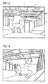
- Figures 1a to 1f shows a mounting process as described above.
- a lining module 1 is transported by workers 2 through an opening 3 into an aircraft 4.
- the workers 2 transport the lining module 1 through a cargo compartment 5 of the aircraft 4.
- a bar structure comprising a plurality of bars 6 is provided which is mounted on the inner walls 7 (here: the side walls and the ceiling) of the aircraft 4.
- the bar structure serves as a supporting means for mounting lining panels 1.
- one worker 2 holds the lining panel 1 and presses it against the bars 6.
- the other worker 2 fixes the lining panel 1 to the bars 6 using screws, as shown in Figure 1e .
- the cargo compartment 5 is ready for use, see Figure 1f .
- an installation device according to claim 1 is provided. Further, a module according to claim 11 and a method of mounting lining panels according to claim 15 is provided. Preferred embodiments and further aspects of the present invention are defined in the subclaims.
- an installation device for installing a lining module in an aircraft comprises a main beam having a first main beam section and a second main beam section and a hinge pivotably connecting a first end of the first main beam section and a first end of the second main beam section with each other such that the first main beam section can be pivoted relative to the second main beam part section about an axis aligned perpendicular to a longitudinal axis of the first main beam section.
- the installation device further comprises a first movable beam provided at a second end of the first main beam section such that it is movable relative to the first main beam section along a longitudinal axis thereof, and a second movable beam provided at a second end of the second main beam section such that it is movable relative to the second main beam section along a longitudinal axis thereof.
- a first longitudinal element is connected to an end of the first movable beam facing away from the first main beam section
- a second longitudinal element is connected to an end of the second movable beam facing away from the second main beam section. Due to the use of movable beams, the installation device can be made very compact during transport, and extended on demand during installation. Further, due to the use of the longitudinal elements, the lining panels can be positioned very easily which will be described later in more detail.
- the hinge may comprise a damping means which dampens the pivoting of the first main beam section relative to the second main beam section.
- the pivoting can be carried out in a controlled manner.
- An end of the first longitudinal element may facing away from the first movable member may be connected to a first hook, and/or an end of the second longitudinal element facing away from the second movable member may be connected to a second hook.
- the installation device can be connected to a fixing structure via the hooks quite easily.
- the first longitudinal element may be connected to a third hook provided between the first hook and the first movable member, and/or the second longitudinal element may be connected to a fourth hook provided between the second hook and the second movable member. This enables to suspend the installation device from a fixing structure at different heights.
- the second end of the first main beam section has the shape of a tube into which at least a part of the first movable beam is inserted, wherein the inserted part of the first movable beam is movable within the tube along the longitudinal axis of the first main beam section.
- the second end of the second main beam section has the shape of a tube into which at least a part of the second movable beam is inserted, wherein the inserted part of the second movable beam is movable within the tube along the longitudinal axis of the second main beam section.
- a first slit may be provided in a wall of the second end of the first main beam section, wherein the inserted part of the first movable beam is connected to a first protruding element which penetrates through the first slit, and wherein, by sliding the first protruding element along the first slit, the first movable beam is moved along the longitudinal axis of the first main beam section.
- a second slit may be provided in a wall of the second end of the second main beam section, wherein the inserted part of the second movable beam is connected to a second protruding element which penetrates through the second slit, and wherein, by sliding the second protruding element along the second slit, the second movable beam is moved along the longitudinal axis of the second main beam section.
- the first protruding element may be adapted to be switched from a first state in which sliding along the first slit is possible, into a second state in which sliding along the first slit is blocked, and vice versa.
- the second protruding element can be switched from a second state in which sliding along the second slit is possible, into a second state in which sliding along the second slit is blocked, and vice versa.
- an undesired movement of the first movable beam or the second movable beam during transportation of the installation device can be prevented.
- At least parts of the outer surface of the first main beam section and the second main beam section may be respectively covered with a damping element.
- the damping element may be a foam layer.
- the longitudinal elements may for example be flexible ropes or rigid rods pivotably connected to the movable beams.
- a package comprising at least one installation device according to any embodiment of the present invention, and at least one lining panel wrapped around the at least one installation device, the at least one lining panel being adapted to be mounted to a bar structure within an aircraft.
- a surface of the at least one lining panel facing towards the at least one installation device may comprise removably attached fixing elements at which hooks can be fixed.
- the package may comprise two installation devices which are spaced apart from each other and are aligned parallel to each other, wherein a lining panel may be wrapped around the installation devices such that two opposing edges of the lining panel which are aligned parallel to the longitudinal axes of the installation devices are connected with each other (e.g. via a zipper) or overlap with each other. Due to the overlap, the length of the lining panel can be increased, thereby being able to transport in a very compact manner a large lining panel.
- the first longitudinal element and/or the second longitudinal element may extend over edges of the lining panel aligned perpendicular to the longitudinal axes of the installation devices. This makes it possible to use the longitudinal elements as grips when lifting the package should it be not possible to grasp the first/second movable beam (which may be covered by the wrapped lining panel).
- a method of mounting lining panels of packages according to any embodiment of the present invention to a bar structure within an aircraft comprises connecting the longitudinal elements of a first package to a fixing structure which is removably connected to the bar structure, thereby suspending the at least one installation device and thus the whole first module from the bar structure.
- the method further comprises de-wrapping parts of a first lining panel from the at least one installation device, and fixing the de-wrapped parts or other parts of the first lining panel to the bar structure while the at least one installation device supports the other parts of the first lining panel during the fixing process.
- the longitudinal elements are removed from the fixing structure in order to remove the at least one installation device.
- the fixing structure may comprise mounting bridges which are detachably attachable to a pair of adjacent bars of the bar structure such that each mounting bridge connects the adjacent bars, wherein the longitudinal elements are fixed to a part of the mounting bridges which is located between the adjacent bars, and wherein an edge of the lining panel is positioned below one of the pair of beams for fixation, however the lining panel does not cover an area between the adjacent bars.
- the longitudinal elements of a second package may be connected to fixing elements removably attached on the surface of the first lining panel which has already been mounted to the bar structure, thereby suspending the at least one installation device and thus the whole second package at least partly from the first lining panel.
- parts of a second lining panel may be de-wrapped from the at least one installation device, and the de-wrapped parts or other parts of the second lining panel may be fixed to the bar structure while the at least one installation device supports the other parts of the lining panel.
- the longitudinal elements may be removed from the removably attached fixing elements in order to remove the at least one installation device. Due to the use of removable fixing elements, the first lining panel can be used as fixing structure. This makes it possible to locate the fixing structure away from the bar where the lining panel is fixed. As a consequence, the positioning process of the lining panel relative to the bar of the bar structure where the lining panel is to be fixed is more easy.
- FIG. 2 shows an installation device 50 for installing a lining module in an aircraft.
- the installation device 50 comprises a main beam 51 having a first main beam section 52 and a second main beam section 53 and a hinge 54 pivotably connecting a first end 55 of the first main beam section 52 and a first end 56 of the second main beam section 53 with each other such that the first main beam section 52 can be pivoted relative to the second main beam section 53 about an axis A1 aligned perpendicular to a longitudinal axis A2 of the first main beam section 52.
- the installation device 50 further comprises a first movable beam 57 provided at a second end 58 of the first main beam section 52 such that it is movable relative to the first main beam section 52 along a longitudinal axis A2 thereof, and a second movable beam 59 provided at a second end 60 of the second main beam section 53 such that it is movable relative to the second main beam section 53 along a longitudinal axis A3 thereof.
- a first longitudinal element 61 is connected to an end of the first movable beam 57 facing away from the first main beam section 52
- a second longitudinal element 62 is connected to an end of the second movable beam 59 facing away from the second main beam section 53.
- the longitudinal elements 61, 62 are flexible ropes.
- parts of the outer surface of the first main beam section 52 and the second main beam section 53 are respectively covered with damping elements 75 (foam layers).
- the hinge 54 may comprise a damping means (not shown) which dampens the pivoting of the first main beam section 52 relative to the second main beam section 53.
- An end 63 of the first longitudinal element 61 facing away from the first movable beam 57 is connected to a first hook 64
- an end 65 of the second longitudinal element 62 facing away from the second movable beam 59 is connected to a second hook 66.
- the first longitudinal element 61 is further connected to a third hook 67 provided between the first hook 64 and the first movable beam 57
- the second longitudinal element 62 is connected to a fourth hook 68 provided between the second hook 66 and the second movable beam 59.
- the second end 58 of the first main beam section 52 has the shape of a tube into which a part of the first movable beam 57 is inserted, wherein the inserted part of the first movable beam 57 is movable within the tube along the longitudinal axis A2 of the first main beam section 52.
- the second end 60 of the second main beam section 53 has the shape of a tube into which a part of the second movable beam 59 is inserted, wherein the inserted part of the second movable beam 59 is movable within the tube along the longitudinal axis A3 of the second main beam section 53.
- the first movable beam 57 may be fully inserted into the first main beam section 52
- the second movable beam 59 may be fully inserted into the second main beam section 53.
- a first slit 69 is provided in a side wall 70 at the second end 58 of the first main beam section 52, wherein the inserted part of the first movable beam 57 is connected to a first protruding element 71 which penetrates through the first slit 69.
- the first protruding element 71 By sliding the first protruding element 71 along the first slit 69, the first movable beam 57 is moved along the longitudinal axis A2 of the first main beam section 52.
- a second slit 72 is provided in a wall 73 at the second end 60 of the second main beam section 53, wherein the inserted part of the second movable beam 53 is connected to a second protruding element 74 which penetrates through the second slit 72, and wherein, by sliding the second protruding element 74 along the second slit 72, the second movable beam 59 is moved along the longitudinal axis A3 of the second main beam section 53.
- the first protruding element 71 may be configured to be switched from a first state in which sliding along the first slit 69 is possible, into a second state in which sliding along the first slit 69 is blocked, and vice versa.
- the first protruding element 71 may have a first base part having a male outer shape connected to the first movable beam 57, and a second part having a female inner shape movable (by screwing) on the first part in a direction towards the first slit 69 (first screwing direction) and away from the first slit 69 (second screwing direction).
- the second protruding element 74 may be configured in the same way.
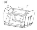
- Figure 3 shows a package 100 comprising a first installation device 50A and a second installation device 50B as described above, and a lining panel 101 wrapped around the installation devices 50A, 50B.
- the lining panel 101 comprises a first lining panel part 101A wrapped around the first main beam sections 52 of the first installation device 50A and of the second installation device 50B, and a second lining panel part 101B wrapped around the second main beam sections 53 of the first installation device 50A and of the second installation device 50B.
- the first lining panel part 101A is separated from the second lining panel part 101B along an area extending around axis A1.
- the installation devices 50A, 50B are spaced apart from each other and are aligned parallel to each other.
- the first main beam section 52 has been pivoted relative to the second main beam section 53 about an axis A1 aligned perpendicular to a longitudinal axis A2 of the first main beam section 52 such that the corresponding first main beam section 52 and the second main beam section 53 form an angle ⁇ with each other of less than 90°.
- the first lining panel part 101A is wrapped around the first main beam sections 52 of the first installation device 50A and of the second installation device 50B such that two opposing edges 120, 121 of the first lining panel part 101A which are aligned parallel to the longitudinal axes A2, A3 of the installation devices 50A, 50B are connected with each other or overlap with each other (see Figure 4 where the opposing edges 120, 121 overlap).
- the same may be true for the second lining panel part 101B.
- the package 100 is temporally placed in a container 102 in order to ease the transportation of the package 100.
- the movable beams 57, 59 are advantageously inserted as much as possible into the main beam sections 52, 53.
- Figure 4 shows a state after the package 100 has been "unfolded", i.e. in each installation device 50A, 50B, the first main beam section 52 has been pivoted relative to the second main beam section 53 about an axis A1 aligned perpendicular to a longitudinal axis A2 of the first main beam section 52 such that the corresponding first main beam section 52 and the second main beam section 53 form an angle ⁇ with each other of 180°.
- the package 100 After having unfolded the package 100, the package 100 is lifted by the workers, and the movable beams 57, 59 are pulled out by moving the protruding elements 71, 74 and introduced into respective mounting elements 103 which are connected to vertically aligned bars 104A of a bar structure comprising vertically aligned bars 104A and horizontally aligned bars 104B which are respectively connected to inner walls 105 of an aircraft.
- the lining panels 101 which are made of flexible material are wrapped around the installation devices 50A, 50B such that, after having introduced the movable beams 57, 59 into the mounting elements 103 connected to the horizontally aligned bars 104B, a first longitudinal end part 106 of the lining panel 101 overlaps a second longitudinal end part 107 of the lining panel in order to be able to use large (long) lining panels, i.e. to transport large lining panels in a compact manner.
- the package 100 has been installed such that the first longitudinal end part 106 and the second longitudinal end part 107 of the lining panel 101 overlap on a lower side of the package 100 (a side facing away from the horizontally aligned bars 104B).
- the longitudinal end parts 106, 107 are then decoupled so that the longitudinal ends 106, 107 suspend from the installation devices 50A, 50B in a vertical direction.
- the part of the lining panel 101 which extends between the installation devices 50A, 50B in a horizontal direction is fixed to the horizontally aligned bars 104B by the workers.
- the installation devices 50A, 50B are successively moved towards the vertically aligned bars 104A by moving the mounting elements 103 along the horizontally aligned bars 104B while fixing further parts of the lining panel 101 to the horizontally aligned bars 104B.
- the installation devices 50A, 50B reach the vertically aligned bars 104B, the remaining parts of the lining panel 101 are fixed to the vertically aligned bars 104A, see Figure 5 .
- the installation devices 50A, 50B hold the lining panel 101 at the horizontally aligned bars 104B during the fixing process so that no extra worker is needed during the fixing process for holding the lining panel 101.
- the installation devices 50A, 50B can be removed by moving the movable beams 57, 59 into the main beam sections 52, 53, thereby moving the movable beams 57, 58 out of the mounting elements 103.
- the removed installation devices 50A, 50B may be reused to manufacture a further package 100.
- a further package 100 may be mounted in the same manner, until the whole bar structure is covered with lining panels 101.
- the mounting elements 103 are rigid elements. Thus, it may not always be easy to introduce the movable beams 57, 58 into the mounting elements 103 or to fine tune the position of the lining panel 101 relative to the bars 104A, 104B after insertion. This problem is addressed by the mounting method which will be described in the following.
- FIG 6 a state is shown in which the first installation device 50A and the second installation device 50B of a first package 100A which respectively comprise first longitudinal elements 61 and second longitudinal elements 62 as shown in Figure 2 .
- Such longitudinal elements 61, 62 do not exist in the embodiment shown in Figures 4 and 5 or are not used in the mounting process should they exist.
- the first longitudinal elements 61 have been connected to a first fixing structure 108.
- the first fixing structure 108 is a horizontally aligned bar like element (profile) which is arranged between two adjacent horizontally aligned bars 104B of the bar structure.
- the first longitudinal elements 61 are fixed to the first fixing structure via the first hook 64.
- the first fixing structure may also be constituted by the leftmost (104B') of the horizontally aligned bars 104B; in this case, the first longitudinal elements 61 may directly be connected to the leftmost bar 104B by the first hooks 64. As shown in Figure 6b , the second longitudinal elements 62 have been connected to a second fixing structure 110.
- the second fixing structure 109 comprises two horizontally aligned mounting bridges 109 which are detachably attached to a pair of adjacent horizontally aligned bars 104B1, 104B2 of the bar structure such that each mounting bridge 109 connects the adjacent bars 104B1, 104B2, wherein the longitudinal elements 62 are fixed to a part 111 of the mounting bridges 109 which is located between the adjacent bars 104B1, 104B2.
- One edge 112 of the lining panel is positioned below one of the pair of bars (bar 104B1), however does not cover an area 113 located between the adjacent bars 104B1, 104B2.
- the second longitudinal elements 62 are fixed to the mounting bridges 109 via the second hook 66.
- the second fixing structure may also be constituted by the leftmost (104B2) of the horizontally aligned bars 104B; in this case, the second longitudinal elements 62 may directly be connected to the leftmost bar 104B2 by the first hooks 64. In this way, the installation devices 50A, 50B and thus the whole first package 100A suspends from the first fixing structure 108 and the second fixing structure 109.
- the method further comprises de-wrapping parts of the lining panel 101 (first lining panel) of the first package 100A from the installation devices 50A, 50B, and fixing the de-wrapped parts or other parts of the first lining panel to the horizontally aligned bars 104B, wherein the installation devices 50A, 50B support other parts of the first lining panel at the same time.
- the longitudinal elements 61, 62 are removed from the fixing structures 108, 110 in order to remove the installation devices 50A, 50B.
- the first package 100A may be lifted further up immediately before the fixing process such that the first longitudinal elements 61 are connected to the first fixing structure 108 via the third hooks 67, and the second longitudinal elements 62 are connected to the second fixing structure 110 via the fourth hooks 68, see e.g. Figure 8 .
- the longitudinal elements 61, 62 are made of flexible material like ropes, the alignment of the first lining panel 101 relative to the horizontally aligned bars 104B before the fixing process is very easy.
- the longitudinal elements 61, 62 may be designed such that the package 100 can be moved by +/- 50mm in the lateral direction.
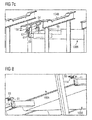
- the first longitudinal elements 61 of a second package 100B may be connected to fixing elements 114 (first fixing structure) removably attached on a lower surface 115 of the first lining panel 101 which has already been mounted to the horizontally aligned bars 104B, thereby suspending the two installation devices 50A, 50B and thus the whole second package 100B partly from the first lining panel 100A.
- parts of the lining panel 101 of the second package 100B (second lining panel 101') is de-wrapped from the installation device 50A, 50B, and the dewrapped parts or other parts of the second lining panel 101' are fixed to the horizontally aligned bars 104B.
- an edge of the 116 of the second lining panel 101' beyond which the movable beams 57 extend is aligned with the edge 112 of the first lining panel 101, i.e. both edges 116, 112 are positioned below the horizontally aligned bar 104B1.
- the longitudinal elements 61, 62 are removed from the removably attached fixing elements 114 in order to remove the installation devices 50A, 50B.
- the fixing elements 114 may be removed und used for preparing a further package 100.
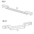
- the fixing element 114 may have a U-shaped section 140 at which the hooks of the longitudinal elements 61, 62 are fixed, and mounting sections 141 (comprising holes 142 for inserting screws) extending from ends of the U-shaped section 140.
- the mounting bridges 109 may have a mounting sections 143 comprising an inverted U shape corresponding to the shape of the horizontally aligned bars 104B, and an intermediate section 144 at which the hooks of the longitudinal elements 61, 62 are fixed.
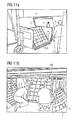
- FIG 11 further illustrates the mounting process as described above.
- a module 100 is transported by workers 2 through an opening 3 into an aircraft 4.
- the workers 2 transport the lining module 100 through a cargo compartment 5 of the aircraft 4.
- a bar structure comprising a plurality of bars 104 is provided which is mounted on the inner walls 7 (here: the side walls and the ceiling) of the aircraft 4.
- the workers 2 grasp the longitudinal elements 61, 62 (ropes) which are hidden below the lining panel 101 and lift the module 100 up while holding the longitudinal elements 61, 62. This effects that the module 100 "unfolds", i.e.
- the first main beam section 52 pivotes relative to the second main beam section 53 about an axis A1 aligned perpendicular to a longitudinal axis A2 of the first main beam section 52 such that the shape of the module 100 becomes flat.
- the lining panel 101 can be dewrapped and fixed to the bars 104, see Figure 11e .
- Different lining panels 101 or different parts 101A, 101B of the same lining panel 101 are connected with each other in a gastight manner using e.g. a zipper 130 (i.e. by closing the zipper), parts of it being provided at opposing longitudinal edges of the lining panels/lining panel parts 101, see Figure 11f .
- the installation devices 50A, 50B can be removed, see Figure 1g .
Landscapes
- Engineering & Computer Science (AREA)
- Aviation & Aerospace Engineering (AREA)
- Manufacturing & Machinery (AREA)
- Mechanical Engineering (AREA)
- Transportation (AREA)
- Connection Of Plates (AREA)
Abstract
Description
- The present invention relates to an installation device for installing a lining panel in an aircraft, a package comprising a lining panel as well as a method of mounting lining panels in an aircraft using an installation device.
- In aircrafts, cargo compartments usually comprise a bar structure which is mounted on the inner walls of the aircraft. The bar structure serves as a supporting means for a plurality of lining panels which are mounted on the bar structure. The lining panels are preferably connected with each other in a gastight manner.
- In order to mount the lining panels on the bar structure, several persons are needed. One person has to hold the lining panel and press it against the bar structure. The other person fixes the lining panel to the bar structure using for example screws. This mounting procedure is very time consuming since at least one person has to hold the lining panel and is thus blocked for other activities.
-
Figures 1a to 1f shows a mounting process as described above. InFigures 1a and 1b , alining module 1 is transported byworkers 2 through anopening 3 into anaircraft 4. InFigure 1c , theworkers 2 transport thelining module 1 through acargo compartment 5 of theaircraft 4. In thecargo department 5, a bar structure comprising a plurality ofbars 6 is provided which is mounted on the inner walls 7 (here: the side walls and the ceiling) of theaircraft 4. The bar structure serves as a supporting means for mountinglining panels 1. InFigure 1d , oneworker 2 holds thelining panel 1 and presses it against thebars 6. Theother worker 2 fixes thelining panel 1 to thebars 6 using screws, as shown inFigure 1e . As soon as allbars 6 of the bar structure have been covered withlining panels 1, thecargo compartment 5 is ready for use, seeFigure 1f . - It is an object of the present invention to provide a means which facilitates the mounting process of lining panels in aircrafts.
- In order to solve the above object, an installation device according to
claim 1 is provided. Further, a module according to claim 11 and a method of mounting lining panels according to claim 15 is provided. Preferred embodiments and further aspects of the present invention are defined in the subclaims. - According to an aspect of the present invention, an installation device for installing a lining module in an aircraft comprises a main beam having a first main beam section and a second main beam section and a hinge pivotably connecting a first end of the first main beam section and a first end of the second main beam section with each other such that the first main beam section can be pivoted relative to the second main beam part section about an axis aligned perpendicular to a longitudinal axis of the first main beam section. The installation device further comprises a first movable beam provided at a second end of the first main beam section such that it is movable relative to the first main beam section along a longitudinal axis thereof, and a second movable beam provided at a second end of the second main beam section such that it is movable relative to the second main beam section along a longitudinal axis thereof. A first longitudinal element is connected to an end of the first movable beam facing away from the first main beam section, and a second longitudinal element is connected to an end of the second movable beam facing away from the second main beam section. Due to the use of movable beams, the installation device can be made very compact during transport, and extended on demand during installation. Further, due to the use of the longitudinal elements, the lining panels can be positioned very easily which will be described later in more detail.
- The hinge may comprise a damping means which dampens the pivoting of the first main beam section relative to the second main beam section. Thus, the pivoting can be carried out in a controlled manner.
- An end of the first longitudinal element may facing away from the first movable member may be connected to a first hook, and/or an end of the second longitudinal element facing away from the second movable member may be connected to a second hook. In this way, the installation device can be connected to a fixing structure via the hooks quite easily.
- The first longitudinal element may be connected to a third hook provided between the first hook and the first movable member, and/or the second longitudinal element may be connected to a fourth hook provided between the second hook and the second movable member. This enables to suspend the installation device from a fixing structure at different heights.
- The second end of the first main beam section has the shape of a tube into which at least a part of the first movable beam is inserted, wherein the inserted part of the first movable beam is movable within the tube along the longitudinal axis of the first main beam section. Alternatively or additionally, the second end of the second main beam section has the shape of a tube into which at least a part of the second movable beam is inserted, wherein the inserted part of the second movable beam is movable within the tube along the longitudinal axis of the second main beam section. Thus, the installation device can be easily extended or compressed on demand.
- A first slit may be provided in a wall of the second end of the first main beam section, wherein the inserted part of the first movable beam is connected to a first protruding element which penetrates through the first slit, and wherein, by sliding the first protruding element along the first slit, the first movable beam is moved along the longitudinal axis of the first main beam section. Alternatively or additionally, a second slit may be provided in a wall of the second end of the second main beam section, wherein the inserted part of the second movable beam is connected to a second protruding element which penetrates through the second slit, and wherein, by sliding the second protruding element along the second slit, the second movable beam is moved along the longitudinal axis of the second main beam section. The first protruding element may be adapted to be switched from a first state in which sliding along the first slit is possible, into a second state in which sliding along the first slit is blocked, and vice versa. Alternatively or additionally, the second protruding element can be switched from a second state in which sliding along the second slit is possible, into a second state in which sliding along the second slit is blocked, and vice versa. Thus, an undesired movement of the first movable beam or the second movable beam during transportation of the installation device can be prevented.
- At least parts of the outer surface of the first main beam section and the second main beam section may be respectively covered with a damping element. The damping element may be a foam layer. Thus, the lining panel can be supported without having the danger of damaging the lining panel (e.g. scratches, etc.)
- The longitudinal elements may for example be flexible ropes or rigid rods pivotably connected to the movable beams.
- According to an aspect of the present invention, a package is provided comprising at least one installation device according to any embodiment of the present invention, and at least one lining panel wrapped around the at least one installation device, the at least one lining panel being adapted to be mounted to a bar structure within an aircraft.
- A surface of the at least one lining panel facing towards the at least one installation device may comprise removably attached fixing elements at which hooks can be fixed. The package may comprise two installation devices which are spaced apart from each other and are aligned parallel to each other, wherein a lining panel may be wrapped around the installation devices such that two opposing edges of the lining panel which are aligned parallel to the longitudinal axes of the installation devices are connected with each other (e.g. via a zipper) or overlap with each other. Due to the overlap, the length of the lining panel can be increased, thereby being able to transport in a very compact manner a large lining panel.
- The first longitudinal element and/or the second longitudinal element may extend over edges of the lining panel aligned perpendicular to the longitudinal axes of the installation devices. This makes it possible to use the longitudinal elements as grips when lifting the package should it be not possible to grasp the first/second movable beam (which may be covered by the wrapped lining panel).
- According to an aspect of the present invention, a method of mounting lining panels of packages according to any embodiment of the present invention to a bar structure within an aircraft is provided. The method comprises connecting the longitudinal elements of a first package to a fixing structure which is removably connected to the bar structure, thereby suspending the at least one installation device and thus the whole first module from the bar structure. The method further comprises de-wrapping parts of a first lining panel from the at least one installation device, and fixing the de-wrapped parts or other parts of the first lining panel to the bar structure while the at least one installation device supports the other parts of the first lining panel during the fixing process. After having fixed the first lining panel to the bar structure, the longitudinal elements are removed from the fixing structure in order to remove the at least one installation device.
- The fixing structure may comprise mounting bridges which are detachably attachable to a pair of adjacent bars of the bar structure such that each mounting bridge connects the adjacent bars, wherein the longitudinal elements are fixed to a part of the mounting bridges which is located between the adjacent bars, and wherein an edge of the lining panel is positioned below one of the pair of beams for fixation, however the lining panel does not cover an area between the adjacent bars.
- The longitudinal elements of a second package may be connected to fixing elements removably attached on the surface of the first lining panel which has already been mounted to the bar structure, thereby suspending the at least one installation device and thus the whole second package at least partly from the first lining panel. After this, parts of a second lining panel may be de-wrapped from the at least one installation device, and the de-wrapped parts or other parts of the second lining panel may be fixed to the bar structure while the at least one installation device supports the other parts of the lining panel. After having fixed the second lining panel to the bar structure, the longitudinal elements may be removed from the removably attached fixing elements in order to remove the at least one installation device. Due to the use of removable fixing elements, the first lining panel can be used as fixing structure. This makes it possible to locate the fixing structure away from the bar where the lining panel is fixed. As a consequence, the positioning process of the lining panel relative to the bar of the bar structure where the lining panel is to be fixed is more easy.
- In the following description, preferred embodiments of the present invention will be explained by way of example while making reference to the accompanying drawings, wherein:
- Figs. 1a) to f)
- show steps of a in a conventional lining panel mounting method;
- Fig. 2
- shows an installation device according to one embodiment of the present invention;
- Fig. 3
- shows a module according to one embodiment of the present invention;
- Fig. 4
- shows a first mounting step of a lining panel mounting method according to a first embodiment of the present invention;
- Fig. 5
- shows a second mounting step of a lining panel mounting method according to the first embodiment of the present invention;
- Fig. 6a)
- shows a first perspective in a first mounting step of a lining panel mounting method according to a second embodiment of the present invention;
- Fig. 6b)
- shows a second perspective in the first mounting step of a lining panel mounting method according to the second embodiment of the present invention;
- Fig. 7a)
- shows a first perspective in a second mounting step of a lining panel mounting method according to the second embodiment of the present invention;
- Fig. 7b)
- shows a second perspective in the second mounting step of a lining panel mounting method according to the second embodiment of the present invention;
- Fig. 7c)
- shows a third perspective in the second mounting step of a lining panel mounting method according to the second embodiment of the present invention;
- Fig. 8)
- shows a third mounting step of a lining panel mounting method according to the second embodiment of the present invention;
- Fig. 9)
- shows a mounting bridge according to an embodiment of the present invention;
- Fig. 10)
- shows a fixing element according to an embodiment of the present invention; and
- Fig. 11a) to g)
- shows steps of a lining panel mounting process according to a third embodiment of the present invention.
-
Figure 2 shows aninstallation device 50 for installing a lining module in an aircraft. Theinstallation device 50 comprises amain beam 51 having a firstmain beam section 52 and a secondmain beam section 53 and ahinge 54 pivotably connecting afirst end 55 of the firstmain beam section 52 and afirst end 56 of the secondmain beam section 53 with each other such that the firstmain beam section 52 can be pivoted relative to the secondmain beam section 53 about an axis A1 aligned perpendicular to a longitudinal axis A2 of the firstmain beam section 52. Theinstallation device 50 further comprises a firstmovable beam 57 provided at asecond end 58 of the firstmain beam section 52 such that it is movable relative to the firstmain beam section 52 along a longitudinal axis A2 thereof, and a secondmovable beam 59 provided at asecond end 60 of the secondmain beam section 53 such that it is movable relative to the secondmain beam section 53 along a longitudinal axis A3 thereof. A firstlongitudinal element 61 is connected to an end of the firstmovable beam 57 facing away from the firstmain beam section 52, and a secondlongitudinal element 62 is connected to an end of the secondmovable beam 59 facing away from the secondmain beam section 53. In this example, thelongitudinal elements main beam section 52 and the secondmain beam section 53 are respectively covered with damping elements 75 (foam layers). - The
hinge 54 may comprise a damping means (not shown) which dampens the pivoting of the firstmain beam section 52 relative to the secondmain beam section 53. - An
end 63 of the firstlongitudinal element 61 facing away from the firstmovable beam 57 is connected to afirst hook 64, and anend 65 of the secondlongitudinal element 62 facing away from the secondmovable beam 59 is connected to asecond hook 66. The firstlongitudinal element 61 is further connected to athird hook 67 provided between thefirst hook 64 and the firstmovable beam 57, and the secondlongitudinal element 62 is connected to afourth hook 68 provided between thesecond hook 66 and the secondmovable beam 59. - The
second end 58 of the firstmain beam section 52 has the shape of a tube into which a part of the firstmovable beam 57 is inserted, wherein the inserted part of the firstmovable beam 57 is movable within the tube along the longitudinal axis A2 of the firstmain beam section 52. Likewise, thesecond end 60 of the secondmain beam section 53 has the shape of a tube into which a part of the secondmovable beam 59 is inserted, wherein the inserted part of the secondmovable beam 59 is movable within the tube along the longitudinal axis A3 of the secondmain beam section 53. The firstmovable beam 57 may be fully inserted into the firstmain beam section 52, and the secondmovable beam 59 may be fully inserted into the secondmain beam section 53. - A
first slit 69 is provided in aside wall 70 at thesecond end 58 of the firstmain beam section 52, wherein the inserted part of the firstmovable beam 57 is connected to a first protrudingelement 71 which penetrates through thefirst slit 69. By sliding the first protrudingelement 71 along thefirst slit 69, the firstmovable beam 57 is moved along the longitudinal axis A2 of the firstmain beam section 52. Likewise, asecond slit 72 is provided in awall 73 at thesecond end 60 of the secondmain beam section 53, wherein the inserted part of the secondmovable beam 53 is connected to a second protruding element 74 which penetrates through thesecond slit 72, and wherein, by sliding the second protruding element 74 along thesecond slit 72, the secondmovable beam 59 is moved along the longitudinal axis A3 of the secondmain beam section 53. - The first protruding
element 71 may be configured to be switched from a first state in which sliding along thefirst slit 69 is possible, into a second state in which sliding along thefirst slit 69 is blocked, and vice versa. For example, the first protrudingelement 71 may have a first base part having a male outer shape connected to the firstmovable beam 57, and a second part having a female inner shape movable (by screwing) on the first part in a direction towards the first slit 69 (first screwing direction) and away from the first slit 69 (second screwing direction). The second protruding element 74 may be configured in the same way. -
Figure 3 shows apackage 100 comprising afirst installation device 50A and asecond installation device 50B as described above, and alining panel 101 wrapped around theinstallation devices lining panel 101 comprises a firstlining panel part 101A wrapped around the firstmain beam sections 52 of thefirst installation device 50A and of thesecond installation device 50B, and a secondlining panel part 101B wrapped around the secondmain beam sections 53 of thefirst installation device 50A and of thesecond installation device 50B. The firstlining panel part 101A is separated from the secondlining panel part 101B along an area extending around axis A1. Theinstallation devices installation device main beam section 52 has been pivoted relative to the secondmain beam section 53 about an axis A1 aligned perpendicular to a longitudinal axis A2 of the firstmain beam section 52 such that the corresponding firstmain beam section 52 and the secondmain beam section 53 form an angle α with each other of less than 90°. The firstlining panel part 101A is wrapped around the firstmain beam sections 52 of thefirst installation device 50A and of thesecond installation device 50B such that two opposing edges 120, 121 of the firstlining panel part 101A which are aligned parallel to the longitudinal axes A2, A3 of theinstallation devices Figure 4 where the opposing edges 120, 121 overlap). The same may be true for the secondlining panel part 101B. Thepackage 100 is temporally placed in acontainer 102 in order to ease the transportation of thepackage 100. - In the package transport state, as shown in
Figure 3 , themovable beams main beam sections -
Figure 4 shows a state after thepackage 100 has been "unfolded", i.e. in eachinstallation device main beam section 52 has been pivoted relative to the secondmain beam section 53 about an axis A1 aligned perpendicular to a longitudinal axis A2 of the firstmain beam section 52 such that the corresponding firstmain beam section 52 and the secondmain beam section 53 form an angle α with each other of 180°. After having unfolded thepackage 100, thepackage 100 is lifted by the workers, and themovable beams elements 71, 74 and introduced into respective mountingelements 103 which are connected to vertically alignedbars 104A of a bar structure comprising vertically alignedbars 104A and horizontally alignedbars 104B which are respectively connected toinner walls 105 of an aircraft. - As can be derived from
Figure 4 , the liningpanels 101 which are made of flexible material are wrapped around theinstallation devices movable beams elements 103 connected to the horizontally alignedbars 104B, a firstlongitudinal end part 106 of thelining panel 101 overlaps a secondlongitudinal end part 107 of the lining panel in order to be able to use large (long) lining panels, i.e. to transport large lining panels in a compact manner. Thepackage 100 has been installed such that the firstlongitudinal end part 106 and the secondlongitudinal end part 107 of thelining panel 101 overlap on a lower side of the package 100 (a side facing away from the horizontally alignedbars 104B). Thelongitudinal end parts installation devices lining panel 101 which extends between theinstallation devices bars 104B by the workers. Then, theinstallation devices bars 104A by moving the mountingelements 103 along the horizontally alignedbars 104B while fixing further parts of thelining panel 101 to the horizontally alignedbars 104B. As soon as theinstallation devices bars 104B, the remaining parts of thelining panel 101 are fixed to the vertically alignedbars 104A, seeFigure 5 . - In this way, the
installation devices lining panel 101 at the horizontally alignedbars 104B during the fixing process so that no extra worker is needed during the fixing process for holding thelining panel 101. After having reached the stage shown inFigure 5 , theinstallation devices movable beams main beam sections movable beams elements 103. The removedinstallation devices further package 100. Then, afurther package 100 may be mounted in the same manner, until the whole bar structure is covered with liningpanels 101. - In the mounting method shown in
Figures 4 and5 has the disadvantage that the mountingelements 103 are rigid elements. Thus, it may not always be easy to introduce themovable beams elements 103 or to fine tune the position of thelining panel 101 relative to thebars - In
Figure 6 a state is shown in which thefirst installation device 50A and thesecond installation device 50B of afirst package 100A which respectively comprise firstlongitudinal elements 61 and secondlongitudinal elements 62 as shown inFigure 2 . Suchlongitudinal elements Figures 4 and5 or are not used in the mounting process should they exist. As shown inFigure 6a , the firstlongitudinal elements 61 have been connected to afirst fixing structure 108. Thefirst fixing structure 108 is a horizontally aligned bar like element (profile) which is arranged between two adjacent horizontally alignedbars 104B of the bar structure. The firstlongitudinal elements 61 are fixed to the first fixing structure via thefirst hook 64. In case that the firstmovable beams 57 are long enough, the first fixing structure may also be constituted by the leftmost (104B') of the horizontally alignedbars 104B; in this case, the firstlongitudinal elements 61 may directly be connected to theleftmost bar 104B by the first hooks 64. As shown inFigure 6b , the secondlongitudinal elements 62 have been connected to asecond fixing structure 110. Thesecond fixing structure 109 comprises two horizontally aligned mountingbridges 109 which are detachably attached to a pair of adjacent horizontally aligned bars 104B1, 104B2 of the bar structure such that each mountingbridge 109 connects the adjacent bars 104B1, 104B2, wherein thelongitudinal elements 62 are fixed to apart 111 of the mountingbridges 109 which is located between the adjacent bars 104B1, 104B2. Oneedge 112 of the lining panel is positioned below one of the pair of bars (bar 104B1), however does not cover anarea 113 located between the adjacent bars 104B1, 104B2. The secondlongitudinal elements 62 are fixed to the mountingbridges 109 via thesecond hook 66. In case that the secondmovable beams 59 are long enough, the second fixing structure may also be constituted by the leftmost (104B2) of the horizontally alignedbars 104B; in this case, the secondlongitudinal elements 62 may directly be connected to the leftmost bar 104B2 by the first hooks 64. In this way, theinstallation devices first package 100A suspends from thefirst fixing structure 108 and thesecond fixing structure 109. - The method further comprises de-wrapping parts of the lining panel 101 (first lining panel) of the
first package 100A from theinstallation devices bars 104B, wherein theinstallation devices first lining panel 101 to the horizontally alignedbars 104B, thelongitudinal elements structures installation devices first lining panel 101 to the horizontally alignedbars 104B, thefirst package 100A may be lifted further up immediately before the fixing process such that the firstlongitudinal elements 61 are connected to thefirst fixing structure 108 via thethird hooks 67, and the secondlongitudinal elements 62 are connected to thesecond fixing structure 110 via thefourth hooks 68, see e.g.Figure 8 . If thelongitudinal elements first lining panel 101 relative to the horizontally alignedbars 104B before the fixing process is very easy. For example, thelongitudinal elements package 100 can be moved by +/- 50mm in the lateral direction. - As shown in
Figure 7 , the firstlongitudinal elements 61 of asecond package 100B may be connected to fixing elements 114 (first fixing structure) removably attached on alower surface 115 of thefirst lining panel 101 which has already been mounted to the horizontally alignedbars 104B, thereby suspending the twoinstallation devices second package 100B partly from thefirst lining panel 100A. After this, parts of thelining panel 101 of thesecond package 100B (second lining panel 101') is de-wrapped from theinstallation device bars 104B. Here, an edge of the 116 of the second lining panel 101' beyond which themovable beams 57 extend is aligned with theedge 112 of thefirst lining panel 101, i.e. bothedges bars 104B, thelongitudinal elements elements 114 in order to remove theinstallation devices elements 114 may be removed und used for preparing afurther package 100. By repeating the above sequence, the whole bar structure 104 can be successively covered with liningpanels 101. - As shown in
Figure 10 , the fixingelement 114 may have a U-shaped section 140 at which the hooks of thelongitudinal elements - As shown in
Figure 9 , the mountingbridges 109 may have a mounting sections 143 comprising an inverted U shape corresponding to the shape of the horizontally alignedbars 104B, and an intermediate section 144 at which the hooks of thelongitudinal elements -
Figure 11 further illustrates the mounting process as described above. InFigure 11a , amodule 100 is transported byworkers 2 through anopening 3 into anaircraft 4. InFigure 11b , theworkers 2 transport thelining module 100 through acargo compartment 5 of theaircraft 4. In thecargo department 5, a bar structure comprising a plurality of bars 104 is provided which is mounted on the inner walls 7 (here: the side walls and the ceiling) of theaircraft 4. InFigure 11c , theworkers 2 grasp thelongitudinal elements 61, 62 (ropes) which are hidden below thelining panel 101 and lift themodule 100 up while holding thelongitudinal elements module 100 "unfolds", i.e. in eachinstallation device main beam section 52 pivotes relative to the secondmain beam section 53 about an axis A1 aligned perpendicular to a longitudinal axis A2 of the firstmain beam section 52 such that the shape of themodule 100 becomes flat. After the module has been suspended from the bars 104 via theinstallation devices Figure 11d , thelining panel 101 can be dewrapped and fixed to the bars 104, seeFigure 11e .Different lining panels 101 ordifferent parts same lining panel 101 are connected with each other in a gastight manner using e.g. a zipper 130 (i.e. by closing the zipper), parts of it being provided at opposing longitudinal edges of the lining panels/liningpanel parts 101, seeFigure 11f . Then, theinstallation devices Figure 1g .
Claims (17)
- An installation device (50) for installing a lining panel (101) in an aircraft (4), comprising:- a main beam (51) having a first main beam section (52) and a second main beam section (53);- a hinge (54) pivotably connecting a first end (55) of the first main beam section (52) and a first end (56) of the second main beam section (53) with each other such that the first main beam section (52) can be pivoted relative to the second main beam section (53) about an axis (A1) aligned perpendicular to a longitudinal axis (A2) of the first main beam section (52);- a first movable beam (57) provided at a second end (58) of the first main beam section (52) such that it is movable relative to the first main beam section (52) along the longitudinal axis (A2) thereof;- a second movable beam (59) provided at a second end (60) of the second main beam section (53) such that it is movable relative to the second main beam section (53) along a longitudinal axis (A3) thereof;- a first longitudinal element (61) connected to an end of the first movable beam (57) facing away from the first main beam section (52); and- a second longitudinal element (62) connected to an end of the second movable beam (59) facing away from the second main beam section (53).
- The installation device (50) according to claim 1,
wherein the hinge (54) comprises a damping means which dampens the pivoting of the first main beam section (52) relative to the second main beam section (53). - The installation device (50) according to any one of claims 1 and 2,
wherein an end (63) of the first longitudinal element (61) facing away from the first movable beam (57) is connected to a first hook (64), and/or wherein an end (65) of the second longitudinal element (62) facing away from the second movable member (53) is connected to a second hook (66). - The installation device (50) according to claim 3,
wherein the first longitudinal element (61) is connected to a third hook (67) provided between the first hook (64) and the first movable member (57), and/or wherein the second longitudinal element (59) is connected to a fourth hook (68) provided between the second hook (66) and the second movable member (59). - The installation device (50) according to any one of the claims 1 to 4,
wherein the second end (58) of the first main beam section (52) has the shape of a tube into which at least a part of the first movable beam (57) is inserted, wherein the inserted part of the first movable beam (57) is movable within the tube along the longitudinal axis (A2) of the first main beam section (52), and/or wherein the second end (60) of the second main beam section (53) has the shape of a tube into which at least a part of the second movable beam (59) is inserted, wherein the inserted part of the second movable beam (59) is movable within the tube along the longitudinal axis (A3) of the second main beam section (53). - The installation device (50) according to claim 5,
wherein a first slit (69) is provided in a wall (70) of the second end of the first main beam section (52), wherein the inserted part of the first movable beam (57) is connected to a first protruding element (71) which penetrates through the first slit (69), and wherein, by sliding the first protruding element (71) along the first slit (69), the first movable element (57) is moved along the longitudinal axis (A2) of the first main beam section (52),
and/or
wherein a second slit (72) is provided in a wall (73) of the second end of the second main beam section (53), wherein the inserted part of the second movable beam (59) is connected to a second protruding element (74) which penetrates through the second slit (72), and wherein, by sliding the second protruding element (74) along the second slit (72), the second movable beam (59) is moved along the longitudinal axis (A3) of the second main beam section (53). - The installation device (50) according to claim 6,
wherein the first protruding element (71) can be switched from a first state in which sliding along the first slit (69) is possible, into a second state in which sliding along the first slit (69) is blocked, and vice versa,
and/or
wherein the second protruding element (74) can be switched from a second state in which sliding along the second slit (72) is possible, into a second state in which sliding along the second slit (72) is blocked, and vice versa. - The installation device (50) according to any one of the claims 1 to 7,
wherein at least parts of the outer surface of the first main beam section (52) and the second main beam section (53) are respectively covered with a damping element (75). - The installation device (50) according to claim 8,
wherein the damping element (75) is a foam layer. - The installation device (50) according to any one of the claims 1 to 9,
wherein the longitudinal elements (61, 62) are ropes. - A package (100), comprising:- at least one installation device (50) according to any one of the claims 1 to 10,- a lining panel (101) wrapped around the at least one installation device (50), the lining panel (101) being adapted to be mounted to a bar structure within an aircraft.
- The package (100) according to claim 11,
wherein a surface of the lining panel (101) facing towards the at least one installation device (50) comprises removably attached fixing elements (114) at which hooks can be fixed. - The package (100) according to any one of the claims 11 and 12,
wherein the package (100) comprises two installation devices (50A, 50B) which are spaced apart from each other and are aligned parallel to each other, wherein the lining panel (101) is wrapped around the installation devices (50A, 50B) such that two opposing edges of the lining panel (101) which are aligned parallel to the longitudinal axes (A2, A3) of the installation devices are connected with each other or opposing longitudinal end parts (106, 107) overlap with each other. - The package (100) according to any one of the claims 11 to 13,
wherein the first longitudinal element (61) and/or the second longitudinal element (62) extend over edges (116) of the lining panel aligned perpendicular to the longitudinal axes (A2, A3) of the installation devices (50A, 50B). - A method of mounting lining panels of packages (100) according to any one of the claims 11 to 14 to a bar structure (104) within an aircraft (4), comprising the following processes:- connecting the longitudinal elements (61, 62) of a first package (100A) to a fixing structure (108, 110) which is removably connected to the bar structure (104), thereby suspending the at least one installation device (50A, 50B) and thus the whole first package (100A) from the bar structure (104);- de-wrapping parts of a first lining panel (101) from the at least one installation device (50A, 50B), and fixing the de-wrapped parts or other parts of the first lining panel (101) to the bar structure (104) while the at least one installation device (50A, 50B) supports the other parts of the first lining panel (101);- after having fixed the first lining panel (101) to the bar structure (104), removing the longitudinal elements (50A, 50B) from the fixing structure (108, 110) in order to remove the at least one installation device (50A, 50B).
- The method according to claim 15,- wherein the fixing structure (110) comprises mounting bridges (109) which are detachably attachable to a pair of adjacent bars (104B1, 104B2) of the bar structure (104) such that each mounting bridge (109) connects the adjacent bars (104B1, 104B2),- wherein the longitudinal elements (61, 62) are fixed to a part (111) of the mounting bridges (109) which is located between the adjacent bars (104B1, 104B2), and- wherein an edge (112) of the first lining panel (101) is positioned below one of the adjacent bars (104B1, 104B2), however the lining panel (101) itself does not cover an area between the adjacent bars104B1, 104B2.
- The method according to any one of claims 15 to 16, further comprising the following processes:- connecting the longitudinal elements (61, 62) of a second package (100B) to fixing elements (114) removably attached on the surface of the first lining panel (101) which has already been mounted to the bar structure (104), thereby suspending the at least one installation device (50A, 50B) and thus the whole second package (100B) at least partly from the first lining panel (101);- de-wrapping parts of a second lining panel (101) from the at least one installation device (50A, 50B), and fixing the de-wrapped parts or other parts of the second lining panel (101) to the bar structure (104) while the at least one installation device (50A, 50B) supports other parts of the lining panel (101);- after having fixed the second lining panel (101) to the bar structure (104), removing the longitudinal elements (61, 62) from the removably attached fixing elements (114) in order to remove the at least one installation device (50A, 50B).
Priority Applications (2)
| Application Number | Priority Date | Filing Date | Title |
|---|---|---|---|
| EP13198539.2A EP2886443B1 (en) | 2013-12-19 | 2013-12-19 | Installation device |
| US14/556,816 US9700995B2 (en) | 2013-12-19 | 2014-12-01 | Installation device |
Applications Claiming Priority (1)
| Application Number | Priority Date | Filing Date | Title |
|---|---|---|---|
| EP13198539.2A EP2886443B1 (en) | 2013-12-19 | 2013-12-19 | Installation device |
Publications (2)
| Publication Number | Publication Date |
|---|---|
| EP2886443A1 true EP2886443A1 (en) | 2015-06-24 |
| EP2886443B1 EP2886443B1 (en) | 2020-06-24 |
Family
ID=49876425
Family Applications (1)
| Application Number | Title | Priority Date | Filing Date |
|---|---|---|---|
| EP13198539.2A Active EP2886443B1 (en) | 2013-12-19 | 2013-12-19 | Installation device |
Country Status (2)
| Country | Link |
|---|---|
| US (1) | US9700995B2 (en) |
| EP (1) | EP2886443B1 (en) |
Families Citing this family (2)
| Publication number | Priority date | Publication date | Assignee | Title |
|---|---|---|---|---|
| AT515159B1 (en) * | 2013-11-20 | 2018-07-15 | Helikopter Air Transp Gmbh | Interior trim part and finished part assembly for an aircraft cell |
| EP2886443B1 (en) * | 2013-12-19 | 2020-06-24 | Airbus Operations GmbH | Installation device |
Citations (2)
| Publication number | Priority date | Publication date | Assignee | Title |
|---|---|---|---|---|
| DE3637490A1 (en) * | 1986-11-04 | 1988-05-05 | Hymer Leichtmetallbau Gmbh | Lightweight-metal plank |
| DE102010017822A1 (en) * | 2010-04-20 | 2011-10-20 | Airbus Operations Gmbh | Airplane interior equipment component and aircraft interior equipment component system |
Family Cites Families (8)
| Publication number | Priority date | Publication date | Assignee | Title |
|---|---|---|---|---|
| US5810333A (en) * | 1997-02-06 | 1998-09-22 | Curtiss Wright Flight Systems Inc. | Ram device |
| US6889968B1 (en) * | 2003-06-02 | 2005-05-10 | Valtra, Inc. | Inserta clamp |
| US7374380B2 (en) * | 2005-12-29 | 2008-05-20 | Han-Ching Huang | Telescopic column |
| GB0724493D0 (en) * | 2007-12-15 | 2008-01-30 | Automotive Prod Italia | Brake adjusters |
| US7490813B1 (en) * | 2008-02-19 | 2009-02-17 | Weddle David R | Rescue tool |
| US9038253B2 (en) * | 2011-04-29 | 2015-05-26 | General Electric Company | System and method for lifting a casing section |
| US9234537B2 (en) * | 2012-11-11 | 2016-01-12 | Han-Ching Huang | Automatically extensible telescopic apparatus |
| EP2886443B1 (en) * | 2013-12-19 | 2020-06-24 | Airbus Operations GmbH | Installation device |
-
2013
- 2013-12-19 EP EP13198539.2A patent/EP2886443B1/en active Active
-
2014
- 2014-12-01 US US14/556,816 patent/US9700995B2/en not_active Expired - Fee Related
Patent Citations (2)
| Publication number | Priority date | Publication date | Assignee | Title |
|---|---|---|---|---|
| DE3637490A1 (en) * | 1986-11-04 | 1988-05-05 | Hymer Leichtmetallbau Gmbh | Lightweight-metal plank |
| DE102010017822A1 (en) * | 2010-04-20 | 2011-10-20 | Airbus Operations Gmbh | Airplane interior equipment component and aircraft interior equipment component system |
Also Published As
| Publication number | Publication date |
|---|---|
| US9700995B2 (en) | 2017-07-11 |
| EP2886443B1 (en) | 2020-06-24 |
| US20150174739A1 (en) | 2015-06-25 |
Similar Documents
| Publication | Publication Date | Title |
|---|---|---|
| AU2014201119B2 (en) | Process and device for replacing idler rollers of a belt conveyor | |
| US8012391B2 (en) | Process for the production of reinforced and cast, cellular or foamed concrete bodies and reinforcement support frame for the use in such a process | |
| US8931749B2 (en) | Base for supporting an upstanding mast | |
| US20110084166A1 (en) | Arrangement for dividing a space into a plurality of areas | |
| US10870476B2 (en) | Interior module installation in an aircraft fuselage | |
| EP3231715B1 (en) | Commercial aircraft interior monument protection system | |
| EP2886443B1 (en) | Installation device | |
| IL262085A (en) | Formwork device | |
| US20190193872A1 (en) | Modular System For Installing Modules On A Fuselage Structure Of A Vehicle | |
| RU2376217C1 (en) | Device to make weightless horizontally moving multi-link mechanical system of spacecraft | |
| CN109071183A (en) | Lifting system and carrier element for such a lifting system | |
| RU2615229C2 (en) | Enclosing frame, method of its installation, application of enclosing frame for connecting frame tower crane with object | |
| JP7370024B1 (en) | Conveyance device | |
| WO2022219949A1 (en) | Storage rack | |
| US8646727B2 (en) | Aircraft hold and aircraft equipped with such a hold | |
| CN118163956A (en) | Assembly system and method for assembling aircraft system components in a triangular area | |
| CN103534426B (en) | Modular structure and module construction method | |
| RU2362724C2 (en) | Cross bar for docking of large space vehicle with carrier rocket equipped with supercaliber payload fairing | |
| JP2026011028A (en) | Frame members for scaffolding structures, scaffolding construction method, and scaffolding removal method | |
| JP2003212451A (en) | Template device for mounting elevator | |
| JPH0978827A (en) | Work floor | |
| JP2026011027A (en) | How to construct and remove scaffolding structures | |
| JP2026011026A (en) | Scaffolding structure and connector for scaffolding structure | |
| EP1140627B1 (en) | A jig loading system | |
| CN111824444A (en) | junction module |
Legal Events
| Date | Code | Title | Description |
|---|---|---|---|
| PUAI | Public reference made under article 153(3) epc to a published international application that has entered the european phase |
Free format text: ORIGINAL CODE: 0009012 |
|
| 17P | Request for examination filed |
Effective date: 20131219 |
|
| AK | Designated contracting states |
Kind code of ref document: A1 Designated state(s): AL AT BE BG CH CY CZ DE DK EE ES FI FR GB GR HR HU IE IS IT LI LT LU LV MC MK MT NL NO PL PT RO RS SE SI SK SM TR |
|
| AX | Request for extension of the european patent |
Extension state: BA ME |
|
| R17P | Request for examination filed (corrected) |
Effective date: 20151201 |
|
| RBV | Designated contracting states (corrected) |
Designated state(s): AL AT BE BG CH CY CZ DE DK EE ES FI FR GB GR HR HU IE IS IT LI LT LU LV MC MK MT NL NO PL PT RO RS SE SI SK SM TR |
|
| STAA | Information on the status of an ep patent application or granted ep patent |
Free format text: STATUS: EXAMINATION IS IN PROGRESS |
|
| 17Q | First examination report despatched |
Effective date: 20181212 |
|
| GRAP | Despatch of communication of intention to grant a patent |
Free format text: ORIGINAL CODE: EPIDOSNIGR1 |
|
| STAA | Information on the status of an ep patent application or granted ep patent |
Free format text: STATUS: GRANT OF PATENT IS INTENDED |
|
| INTG | Intention to grant announced |
Effective date: 20200109 |
|
| GRAS | Grant fee paid |
Free format text: ORIGINAL CODE: EPIDOSNIGR3 |
|
| GRAA | (expected) grant |
Free format text: ORIGINAL CODE: 0009210 |
|
| STAA | Information on the status of an ep patent application or granted ep patent |
Free format text: STATUS: THE PATENT HAS BEEN GRANTED |
|
| AK | Designated contracting states |
Kind code of ref document: B1 Designated state(s): AL AT BE BG CH CY CZ DE DK EE ES FI FR GB GR HR HU IE IS IT LI LT LU LV MC MK MT NL NO PL PT RO RS SE SI SK SM TR |
|
| REG | Reference to a national code |
Ref country code: GB Ref legal event code: FG4D |
|
| REG | Reference to a national code |
Ref country code: CH Ref legal event code: EP |
|
| REG | Reference to a national code |
Ref country code: AT Ref legal event code: REF Ref document number: 1283639 Country of ref document: AT Kind code of ref document: T Effective date: 20200715 |
|
| REG | Reference to a national code |
Ref country code: DE Ref legal event code: R096 Ref document number: 602013070110 Country of ref document: DE |
|
| REG | Reference to a national code |
Ref country code: IE Ref legal event code: FG4D |
|
| PG25 | Lapsed in a contracting state [announced via postgrant information from national office to epo] |
Ref country code: NO Free format text: LAPSE BECAUSE OF FAILURE TO SUBMIT A TRANSLATION OF THE DESCRIPTION OR TO PAY THE FEE WITHIN THE PRESCRIBED TIME-LIMIT Effective date: 20200924 Ref country code: GR Free format text: LAPSE BECAUSE OF FAILURE TO SUBMIT A TRANSLATION OF THE DESCRIPTION OR TO PAY THE FEE WITHIN THE PRESCRIBED TIME-LIMIT Effective date: 20200925 Ref country code: LT Free format text: LAPSE BECAUSE OF FAILURE TO SUBMIT A TRANSLATION OF THE DESCRIPTION OR TO PAY THE FEE WITHIN THE PRESCRIBED TIME-LIMIT Effective date: 20200624 Ref country code: SE Free format text: LAPSE BECAUSE OF FAILURE TO SUBMIT A TRANSLATION OF THE DESCRIPTION OR TO PAY THE FEE WITHIN THE PRESCRIBED TIME-LIMIT Effective date: 20200624 Ref country code: FI Free format text: LAPSE BECAUSE OF FAILURE TO SUBMIT A TRANSLATION OF THE DESCRIPTION OR TO PAY THE FEE WITHIN THE PRESCRIBED TIME-LIMIT Effective date: 20200624 |
|
| REG | Reference to a national code |
Ref country code: LT Ref legal event code: MG4D |
|
| PG25 | Lapsed in a contracting state [announced via postgrant information from national office to epo] |
Ref country code: LV Free format text: LAPSE BECAUSE OF FAILURE TO SUBMIT A TRANSLATION OF THE DESCRIPTION OR TO PAY THE FEE WITHIN THE PRESCRIBED TIME-LIMIT Effective date: 20200624 Ref country code: HR Free format text: LAPSE BECAUSE OF FAILURE TO SUBMIT A TRANSLATION OF THE DESCRIPTION OR TO PAY THE FEE WITHIN THE PRESCRIBED TIME-LIMIT Effective date: 20200624 Ref country code: RS Free format text: LAPSE BECAUSE OF FAILURE TO SUBMIT A TRANSLATION OF THE DESCRIPTION OR TO PAY THE FEE WITHIN THE PRESCRIBED TIME-LIMIT Effective date: 20200624 Ref country code: BG Free format text: LAPSE BECAUSE OF FAILURE TO SUBMIT A TRANSLATION OF THE DESCRIPTION OR TO PAY THE FEE WITHIN THE PRESCRIBED TIME-LIMIT Effective date: 20200924 |
|
| REG | Reference to a national code |
Ref country code: NL Ref legal event code: MP Effective date: 20200624 |
|
| REG | Reference to a national code |
Ref country code: AT Ref legal event code: MK05 Ref document number: 1283639 Country of ref document: AT Kind code of ref document: T Effective date: 20200624 |
|
| PG25 | Lapsed in a contracting state [announced via postgrant information from national office to epo] |
Ref country code: NL Free format text: LAPSE BECAUSE OF FAILURE TO SUBMIT A TRANSLATION OF THE DESCRIPTION OR TO PAY THE FEE WITHIN THE PRESCRIBED TIME-LIMIT Effective date: 20200624 Ref country code: AL Free format text: LAPSE BECAUSE OF FAILURE TO SUBMIT A TRANSLATION OF THE DESCRIPTION OR TO PAY THE FEE WITHIN THE PRESCRIBED TIME-LIMIT Effective date: 20200624 |
|
| PG25 | Lapsed in a contracting state [announced via postgrant information from national office to epo] |
Ref country code: IT Free format text: LAPSE BECAUSE OF FAILURE TO SUBMIT A TRANSLATION OF THE DESCRIPTION OR TO PAY THE FEE WITHIN THE PRESCRIBED TIME-LIMIT Effective date: 20200624 Ref country code: RO Free format text: LAPSE BECAUSE OF FAILURE TO SUBMIT A TRANSLATION OF THE DESCRIPTION OR TO PAY THE FEE WITHIN THE PRESCRIBED TIME-LIMIT Effective date: 20200624 Ref country code: CZ Free format text: LAPSE BECAUSE OF FAILURE TO SUBMIT A TRANSLATION OF THE DESCRIPTION OR TO PAY THE FEE WITHIN THE PRESCRIBED TIME-LIMIT Effective date: 20200624 Ref country code: SM Free format text: LAPSE BECAUSE OF FAILURE TO SUBMIT A TRANSLATION OF THE DESCRIPTION OR TO PAY THE FEE WITHIN THE PRESCRIBED TIME-LIMIT Effective date: 20200624 Ref country code: EE Free format text: LAPSE BECAUSE OF FAILURE TO SUBMIT A TRANSLATION OF THE DESCRIPTION OR TO PAY THE FEE WITHIN THE PRESCRIBED TIME-LIMIT Effective date: 20200624 Ref country code: PT Free format text: LAPSE BECAUSE OF FAILURE TO SUBMIT A TRANSLATION OF THE DESCRIPTION OR TO PAY THE FEE WITHIN THE PRESCRIBED TIME-LIMIT Effective date: 20201026 Ref country code: ES Free format text: LAPSE BECAUSE OF FAILURE TO SUBMIT A TRANSLATION OF THE DESCRIPTION OR TO PAY THE FEE WITHIN THE PRESCRIBED TIME-LIMIT Effective date: 20200624 Ref country code: AT Free format text: LAPSE BECAUSE OF FAILURE TO SUBMIT A TRANSLATION OF THE DESCRIPTION OR TO PAY THE FEE WITHIN THE PRESCRIBED TIME-LIMIT Effective date: 20200624 |
|
| PG25 | Lapsed in a contracting state [announced via postgrant information from national office to epo] |
Ref country code: IS Free format text: LAPSE BECAUSE OF FAILURE TO SUBMIT A TRANSLATION OF THE DESCRIPTION OR TO PAY THE FEE WITHIN THE PRESCRIBED TIME-LIMIT Effective date: 20201024 Ref country code: PL Free format text: LAPSE BECAUSE OF FAILURE TO SUBMIT A TRANSLATION OF THE DESCRIPTION OR TO PAY THE FEE WITHIN THE PRESCRIBED TIME-LIMIT Effective date: 20200624 Ref country code: SK Free format text: LAPSE BECAUSE OF FAILURE TO SUBMIT A TRANSLATION OF THE DESCRIPTION OR TO PAY THE FEE WITHIN THE PRESCRIBED TIME-LIMIT Effective date: 20200624 |
|
| REG | Reference to a national code |
Ref country code: DE Ref legal event code: R097 Ref document number: 602013070110 Country of ref document: DE |
|
| PG25 | Lapsed in a contracting state [announced via postgrant information from national office to epo] |
Ref country code: DK Free format text: LAPSE BECAUSE OF FAILURE TO SUBMIT A TRANSLATION OF THE DESCRIPTION OR TO PAY THE FEE WITHIN THE PRESCRIBED TIME-LIMIT Effective date: 20200624 |
|
| PLBE | No opposition filed within time limit |
Free format text: ORIGINAL CODE: 0009261 |
|
| STAA | Information on the status of an ep patent application or granted ep patent |
Free format text: STATUS: NO OPPOSITION FILED WITHIN TIME LIMIT |
|
| 26N | No opposition filed |
Effective date: 20210325 |
|
| REG | Reference to a national code |
Ref country code: DE Ref legal event code: R119 Ref document number: 602013070110 Country of ref document: DE |
|
| REG | Reference to a national code |
Ref country code: CH Ref legal event code: PL |
|
| GBPC | Gb: european patent ceased through non-payment of renewal fee |
Effective date: 20201219 |
|
| PG25 | Lapsed in a contracting state [announced via postgrant information from national office to epo] |
Ref country code: SI Free format text: LAPSE BECAUSE OF FAILURE TO SUBMIT A TRANSLATION OF THE DESCRIPTION OR TO PAY THE FEE WITHIN THE PRESCRIBED TIME-LIMIT Effective date: 20200624 Ref country code: MC Free format text: LAPSE BECAUSE OF FAILURE TO SUBMIT A TRANSLATION OF THE DESCRIPTION OR TO PAY THE FEE WITHIN THE PRESCRIBED TIME-LIMIT Effective date: 20200624 |
|
| REG | Reference to a national code |
Ref country code: BE Ref legal event code: MM Effective date: 20201231 |
|
| PG25 | Lapsed in a contracting state [announced via postgrant information from national office to epo] |
Ref country code: IE Free format text: LAPSE BECAUSE OF NON-PAYMENT OF DUE FEES Effective date: 20201219 Ref country code: LU Free format text: LAPSE BECAUSE OF NON-PAYMENT OF DUE FEES Effective date: 20201219 Ref country code: FR Free format text: LAPSE BECAUSE OF NON-PAYMENT OF DUE FEES Effective date: 20201231 |
|
| PG25 | Lapsed in a contracting state [announced via postgrant information from national office to epo] |
Ref country code: DE Free format text: LAPSE BECAUSE OF NON-PAYMENT OF DUE FEES Effective date: 20210701 Ref country code: GB Free format text: LAPSE BECAUSE OF NON-PAYMENT OF DUE FEES Effective date: 20201219 Ref country code: CH Free format text: LAPSE BECAUSE OF NON-PAYMENT OF DUE FEES Effective date: 20201231 Ref country code: LI Free format text: LAPSE BECAUSE OF NON-PAYMENT OF DUE FEES Effective date: 20201231 |
|
| PG25 | Lapsed in a contracting state [announced via postgrant information from national office to epo] |
Ref country code: IS Free format text: LAPSE BECAUSE OF FAILURE TO SUBMIT A TRANSLATION OF THE DESCRIPTION OR TO PAY THE FEE WITHIN THE PRESCRIBED TIME-LIMIT Effective date: 20201024 Ref country code: TR Free format text: LAPSE BECAUSE OF FAILURE TO SUBMIT A TRANSLATION OF THE DESCRIPTION OR TO PAY THE FEE WITHIN THE PRESCRIBED TIME-LIMIT Effective date: 20200624 Ref country code: MT Free format text: LAPSE BECAUSE OF FAILURE TO SUBMIT A TRANSLATION OF THE DESCRIPTION OR TO PAY THE FEE WITHIN THE PRESCRIBED TIME-LIMIT Effective date: 20200624 Ref country code: CY Free format text: LAPSE BECAUSE OF FAILURE TO SUBMIT A TRANSLATION OF THE DESCRIPTION OR TO PAY THE FEE WITHIN THE PRESCRIBED TIME-LIMIT Effective date: 20200624 |
|
| PG25 | Lapsed in a contracting state [announced via postgrant information from national office to epo] |
Ref country code: MK Free format text: LAPSE BECAUSE OF FAILURE TO SUBMIT A TRANSLATION OF THE DESCRIPTION OR TO PAY THE FEE WITHIN THE PRESCRIBED TIME-LIMIT Effective date: 20200624 |
|
| PG25 | Lapsed in a contracting state [announced via postgrant information from national office to epo] |
Ref country code: BE Free format text: LAPSE BECAUSE OF NON-PAYMENT OF DUE FEES Effective date: 20201231 |