EP2886434A1 - Bicycle crank arm assembly - Google Patents
Bicycle crank arm assembly Download PDFInfo
- Publication number
- EP2886434A1 EP2886434A1 EP14003599.9A EP14003599A EP2886434A1 EP 2886434 A1 EP2886434 A1 EP 2886434A1 EP 14003599 A EP14003599 A EP 14003599A EP 2886434 A1 EP2886434 A1 EP 2886434A1
- Authority
- EP
- European Patent Office
- Prior art keywords
- crank arm
- insert
- support member
- bicycle crank
- outer shell
- Prior art date
- Legal status (The legal status is an assumption and is not a legal conclusion. Google has not performed a legal analysis and makes no representation as to the accuracy of the status listed.)
- Granted
Links
Images



Classifications
-
- B—PERFORMING OPERATIONS; TRANSPORTING
- B62—LAND VEHICLES FOR TRAVELLING OTHERWISE THAN ON RAILS
- B62M—RIDER PROPULSION OF WHEELED VEHICLES OR SLEDGES; POWERED PROPULSION OF SLEDGES OR SINGLE-TRACK CYCLES; TRANSMISSIONS SPECIALLY ADAPTED FOR SUCH VEHICLES
- B62M3/00—Construction of cranks operated by hand or foot
-
- B—PERFORMING OPERATIONS; TRANSPORTING
- B62—LAND VEHICLES FOR TRAVELLING OTHERWISE THAN ON RAILS
- B62M—RIDER PROPULSION OF WHEELED VEHICLES OR SLEDGES; POWERED PROPULSION OF SLEDGES OR SINGLE-TRACK CYCLES; TRANSMISSIONS SPECIALLY ADAPTED FOR SUCH VEHICLES
- B62M3/00—Construction of cranks operated by hand or foot
- B62M3/16—Accessories
-
- Y—GENERAL TAGGING OF NEW TECHNOLOGICAL DEVELOPMENTS; GENERAL TAGGING OF CROSS-SECTIONAL TECHNOLOGIES SPANNING OVER SEVERAL SECTIONS OF THE IPC; TECHNICAL SUBJECTS COVERED BY FORMER USPC CROSS-REFERENCE ART COLLECTIONS [XRACs] AND DIGESTS
- Y10—TECHNICAL SUBJECTS COVERED BY FORMER USPC
- Y10T—TECHNICAL SUBJECTS COVERED BY FORMER US CLASSIFICATION
- Y10T74/00—Machine element or mechanism
- Y10T74/21—Elements
- Y10T74/2164—Cranks and pedals
Definitions
- This invention relates to bicycles and bicycle crank arms.
- the invention relates to composite bicycle crank arm assemblies.
- a crank arm is a component for connecting a pedal to a crank axle of a bicycle and for transmitting a pedal force from the pedal to a chain.
- the crank arm should have high strength in order to prevent failure due to repeated loads from the pedal.
- the crank arm should not be unnecessarily heavy in order to keep the bicycle as light as possible.
- Composite materials generically known as fiber reinforced plastic "FRP," e.g., carbon and other fiber based composites, are advantageous in this respect, providing strong and light construction for the manufacture of modern bicycle cranks. However, composite construction is typically costly.
- the invention provides, in one aspect, a hybrid crank arm that utilizes a full length support member and a composite overwrap to achieve sufficient strength.
- the support member is pocketed between the ends of the crank arm and the pocket or pockets are filled with a relatively low density insert. This support member and insert subassembly is then overwrapped with composite material and cured to form a structurally bonded assembly.
- One aspect of the invention is a bicycle crank arm including a support member.
- the support member includes a first end sized and shaped to receive a pedal and a second end opposite the first end.
- the second end is sized and shaped to receive a spindle and a middle portion extends between the first and second ends, wherein the middle portion includes at least one recess.
- An insert is disposed in the recess and an outer shell that covers the support member and insert, wherein the outer shell is made of fiber reinforced composite material, such as fiber reinforced plastic, for example.
- the middle portion may include a first flange and a second flange spaced apart from the first flange and a connecting portion extending between the first and second flanges.
- the connecting portion may be positioned between an inboard side of the crank arm and an outboard side of the crank arm.
- the connecting portion may be positioned about equally between the inboard side of the crank arm and the outboard side of the crank arm.
- the connecting portion may be positioned closer to an outboard side of the crank arm than an inboard side of the crank arm.
- the outer shell may be thinner on the outboard side of the crank arm.
- the outer shell may be thinner at the first and second ends compared to between the first and second ends.
- the support member may be metallic.
- the support member may include an aluminum material.
- the support member may include a non-metallic material.
- the insert may be less dense than the support member.
- the insert may have a volume that is about that of the recess.
- the insert may have a volume that is greater than that of the recess.
- the insert may be a foamed polymeric material such as polyurethane foam.
- the insert may be a wax material.
- the insert may have a density from about 0.1 to about 0.9 g/cm 3 .
- the insert may have a density of about 0.3 g/cm 3 .
- crank arm 10 according to an embodiment of the invention. While the crank arm 10 illustrated is a non-drive side crank arm, the same construction could be employed on the drive side of a bicycle by providing, for example, additional and well-known structure to attach a chainring carrier and/or a chainring thereto.
- the crank arm 10 includes a first end 12, which is distally located, to which a pedal can be affixed and a second end 14, which is proximally located, to attach the crank arm to a spindle or the like (not shown) in a conventional manner.
- the term spindle in this application, should be considered any type of axle or shaft-like element of a bottom bracket on which the crank arms are mounted.
- Fig. 3 shows two of the main components of the crank arm 10.
- the crank arm 10 includes a full-length support member 16, which is a rigid, mostly internal element, with a pocket or recess 18 formed therein.
- the recess 18 is formed in the inboard side 22 of the support member 16 of the crank arm 10, i.e., wherein the inboard side is the side of the crank arm facing the bicycle frame when mounted on the spindle.
- the opposite configuration is also contemplated by the invention, i.e., wherein the recess 18 is formed on the outboard side 23.
- Figs. 4 , 5A-C and 10 show cross sections (lengthwise and transverse, respectively) of the crank arm 10 of an embodiment of the invention.
- Three main components form the structure of the crank arm 10. These components are the support member 16, the insert 20 and an outer shell 24.
- the support member 16 has three main portions.
- the first end 12 includes a threaded opening 28.
- the threaded opening 28 is sized and shaped to receive the threads of a pedal (not shown).
- the second end 14, opposite the first end 12, is sized and shaped to receive a spindle (not shown).
- the second end 14 may include an opening provided with splines 32 or the like for securing the crank arm 10 to the spindle.
- the exact configuration of the splines 32 is dependent upon the configuration of the spindle, which is a well-known component.
- the middle portion 34 Extending between the first end 12 and the second end 14 is a middle portion 34, which may be in the form of a rib or beam.
- the middle portion 34 includes a first flange 36 and a second flange 38 and a connecting portion 40, which may be in the form of a web, which extends between the first and second flanges.
- the middle portion 34 may generally be in the form of a "C".
- the connecting portion 40 may be oriented to the outboard side 23 of the crank arm 10 when mounted to a spindle of a bicycle, i.e., facing away from the bicycle frame. If the connecting portion 40 is oriented to the outboard side of the crank arm 10, the recess 18 is formed in and opens to the inboard side 22 of the middle portion 34.
- the connecting portion 40 may be oriented to the inboard side 22 of the crank arm. If the connecting portion 40 is oriented to the inboard side 22 of the crank arm 10, the recess 18 is formed in and opens to the outboard side 23 of the middle portion 34.
- the connecting portion 40 may be generally centrally positioned, i.e., about equally spaced between the inboard and outboard sides 22, 23, and define an inside recess 18A and an outside recess 18B.
- Each of the inside and outside recesses 18A, B may include a respective insert 20A, 20B disposed therein.
- the thickness of the outer shell 24 may be the same on the inboard side 22 and the outboard side 23 of the crank arm 10.
- the support member 16 may be formed of a metallic material and manufactured using methods such as forging or casting. Aluminum and alloys thereof are a particularly good choice due to low weight and high strength. In an embodiment where the support member 16 is formed, for example, of an aluminum alloy, the first end 12, the second end 14 and middle portion 34 can be formed as a single-piece, i.e., as a one-piece construction.
- Other suitable materials of the support member 16 include steel, titanium, scandium, beryllium, magnesium, and other similar suitable materials, alloys and combinations thereof.
- the middle portion 34 of the support member 16 may be made of bulk chopped fiber reinforced composite, such as bulk molding compound (BMC) or sheet molding compound (SMC), by any process suitable for the desired material.
- BMC bulk molding compound
- SMC sheet molding compound
- the first end 12 and the second end 14 may be separate metallic inserts that are bonded to and/or mechanically interlocked with the composite middle portion 34 or made of fiber-reinforced composite or plastic material, as is known in the art.
- the support member 16 may be designed such that it by itself cannot structurally sustain the load applied to a typical crank arm in order to minimize the weight of the support member.
- the support member 16 allows for less composite material to be used in the outer shell 24 compared to a more traditional composite crank construction, which reduces the overall cost to manufacture a crank arm 10 of the invention.
- the support member 16, between the first end 12 and the second end 14, i.e., the middle portion 34, may be formed in the shape of a "C" in one embodiment, and its wall thickness may be less than about three (3) millimeters to minimize weight.
- a "C" shaped support member 16 is shown in Figs. 5A-C .
- the wall thickness of the connecting portion 40 of the middle portion 34 may be about 1.5-2 millimeters and the upper and lower flanges 36, 38 may be more than about 1.5 millimeters, for example, to about 3 millimeters. It will be understood that the exact thickness of the various portions will be dependent upon, at least in part, the material used in the part and the manufacturing process.
- the support member 16 may be forged and further machined to a lesser wall thickness that current forging processes permit.
- the combination of the support member 16 and the bonded composite outer shell 24 are sized and shaped to produce a closed section that will withstand the loads seen in use.
- the insert 20 is "D"-shaped in the above-illustrated embodiment shown in Fig. 5A and may be a preformed element.
- the insert 20 may be manufactured into its final form and then positioned within the recess 18 of the support member 16.
- the insert 20 may be shaped and sized to fill, or slightly overfill, the recess 18.
- the insert 20 may be shaped and sized to almost fill the recess 18.
- the insert 20 is mainly used to fill the center middle portion of the crank arm defined by the recess 18 with a low density material to reduce the overall crank arm weight.
- the insert 20 may also be configured to provide the necessary support required to consolidate the adjacent outer composite material forming the outer shell 24 during the curing process. In this manner, the exact final shape of the crank arm 10 can be controlled and the function of the insert 20 in supporting the outer shell 24 during manufacturing is predictable.
- Figs. 5B and C and Fig. 10 show inserts 20 that have one or more voids or pockets 50.
- the pockets 50 may be open to the recess 18 so that the shell 24 is supported.
- Pockets 50 may be round or non-round and may have a longitudinal axis that is aligned transversely or non-transversely.
- the material of the insert 20 may include many materials, but polyurethane foam is one preferred material because it can readily be cast to net shape and is low in density. Other types of foam can be used such as Rohacell®, a polymethacrylimide. Another example is a polymer-based honeycomb material.
- the insert 20 could also be made of a more rigid material like wax, or a low melt metal alloy.
- the insert 20 may be removed after the outer shell 24 is overwrapped thereabout and cured, which leaves a hollow void in the form of the recess 18.
- Polyurethane foam is beneficial as an insert material, since it can be made slightly larger than the recess 18 to provide support for the outer shell 24 and will compress as needed. A wax insert will expand slightly when heated to provide support in the same fashion.
- the insert 20 a density about 0.1-0.9 g/cm 3 (where "g” is grams and “cm” is centimeters) is desirable for the insert 20.
- a density about 0.3 g/cm 3 is preferred.
- Foam densities can be as low as 0.03 g/cm 3 . If the insert 20 is removable, as in the wax example, the density could be higher without negative effects due to higher weight.
- the invention contemplates a ribbed structure with a skin on the one side that faces the outer shell.
- the support member/insert subassembly 16, 20 is covered with fiber reinforced composite material, such as FRP, to form a composite outer shell 24 largely covering the subassembly.
- the shell 24 covers a majority of the outside of the crank arm 10. In other embodiments, the shell 24 may cover all of the outside surface of the crank arm 10 or a minority of the crank arm.
- the assembly 16, 20, 24 is then cured together to form a structurally bonded crank arm 10. The result is a lighter weight composite crank that is inexpensive to manufacture.
- Fiber reinforced resin can be used to construct the composite outer shell 24.
- Unidirectional or woven "prepreg” pre-impregnated composite fibers
- SMC sheet molding compound
- BMC bulk molding compound
- Fiber material used in the composite may include one or more of carbon fiber, glass fiber, aramid fiber and other suitable fibers.
- the composite shell can be thinner in the area abutting the connecting portion 40 of the support member "C" portion since locally the support member provides significant structure by itself.
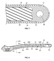
- the thickness of composite material can be reduced on the ends 12, 14, as shown in Fig. 7 , because the structure of the ends 12, 14 provide a significant amount of support. Structurally there is a lesser amount of load at the ends 12, 14 of the crank arm 10 so the thickness of the composite shell locally can be reduced to save additional material. Less composite material also reduces the manual layup time, which further reduces the cost to manufacture.
- the composite outer shell 24 is initially made up of multiple layers of uncured fiber reinforced resin. These layers can be strategically overlapped with each other and the "C" section geometry of the support member 16 to achieve more structural inter-connectivity. The large contact area between the support member 16 and the composite outer shell 24 maximizes the bond area of the fiber reinforced resin to provide for superior structural connection to the support member.
- the outer shell 24 may be formed from two main layers, an inside shell layer 44 that overlays and spans the inboard side 22 against the insert 20 and upper and lower flanges 36, 38, and an outside shell layer 46 that overlays the outboard side 23 against the middle portion 34 and the parts of the inside shell layer that overlays and spans the upper and lower flanges 36, 38.
- the inside shell layer 44 and outside shell layer 46 may each be made of multiple layers of FRP material. In one embodiment, the outside shell layer 46 has less layers of FRP material than the inside shell layer 44.
Landscapes
- Engineering & Computer Science (AREA)
- Chemical & Material Sciences (AREA)
- Combustion & Propulsion (AREA)
- Transportation (AREA)
- Mechanical Engineering (AREA)
- Shafts, Cranks, Connecting Bars, And Related Bearings (AREA)
Abstract
Description
- This invention relates to bicycles and bicycle crank arms. In particular the invention relates to composite bicycle crank arm assemblies.
- A crank arm is a component for connecting a pedal to a crank axle of a bicycle and for transmitting a pedal force from the pedal to a chain. The crank arm should have high strength in order to prevent failure due to repeated loads from the pedal. On the other hand, the crank arm should not be unnecessarily heavy in order to keep the bicycle as light as possible. Composite materials, generically known as fiber reinforced plastic "FRP," e.g., carbon and other fiber based composites, are advantageous in this respect, providing strong and light construction for the manufacture of modern bicycle cranks. However, composite construction is typically costly.
- The invention provides, in one aspect, a hybrid crank arm that utilizes a full length support member and a composite overwrap to achieve sufficient strength. The support member is pocketed between the ends of the crank arm and the pocket or pockets are filled with a relatively low density insert. This support member and insert subassembly is then overwrapped with composite material and cured to form a structurally bonded assembly.
- One aspect of the invention is a bicycle crank arm including a support member. The support member includes a first end sized and shaped to receive a pedal and a second end opposite the first end. The second end is sized and shaped to receive a spindle and a middle portion extends between the first and second ends, wherein the middle portion includes at least one recess. An insert is disposed in the recess and an outer shell that covers the support member and insert, wherein the outer shell is made of fiber reinforced composite material, such as fiber reinforced plastic, for example.
- Other aspects of the invention provide a bicycle crank arm wherein the support member is a one-piece construction. The middle portion may include a first flange and a second flange spaced apart from the first flange and a connecting portion extending between the first and second flanges. The connecting portion may be positioned between an inboard side of the crank arm and an outboard side of the crank arm. The connecting portion may be positioned about equally between the inboard side of the crank arm and the outboard side of the crank arm. The connecting portion may be positioned closer to an outboard side of the crank arm than an inboard side of the crank arm. The outer shell may be thinner on the outboard side of the crank arm. The outer shell may be thinner at the first and second ends compared to between the first and second ends. The support member may be metallic. The support member may include an aluminum material. The support member may include a non-metallic material. The insert may be less dense than the support member. The insert may have a volume that is about that of the recess. The insert may have a volume that is greater than that of the recess. The insert may be a foamed polymeric material such as polyurethane foam. The insert may be a wax material. The insert may have a density from about 0.1 to about 0.9 g/cm3. The insert may have a density of about 0.3 g/cm3.
- These and other features and advantages of the present invention will be more fully understood from the following description of one or more embodiments of the invention, taken together with the accompanying drawings.
- In the drawings:
- Fig. 1
- is an outside view of a crank arm according to the invention;
- Fig. 2
- is a top view of a crank arm according to the invention;
- Fig. 3
- is an exploded perspective view of part of the crank arm of
Fig. 1 according to an embodiment of the invention; - Fig. 4
- is a lengthwise cross sectional view of the crank arm of
Fig. 1 along line A-A; - Figs. 5A-C
- are various embodiments of a crank arm through a transverse cross sectional view as indicated in
Fig. 1 along line B-B; - Fig. 6
- is a transverse cross sectional view of the crank arm of
Fig. 1 showing the orientation of the layers of an outer shell along line B-B ofFig. 1 ; - Fig. 7
- is a partial cross sectional view of the distal end of the crank arm of
Fig. 1 ; - Fig. 8
- is a lengthwise cross sectional view of a crank arm according to a second embodiment of the invention taken along a line like that shown in
Fig. 1 as A-A; - Fig. 9
- is a transverse cross sectional view of the crank arm of
Fig. 8 along line C-C; and - Fig. 10
- is an embodiment of a crank arm with a further embodiment of an insert.
- Embodiments of the invention will herein be described with reference to the drawings. Moreover, the terms employed herein refer to bicycle components conventionally mounted to a bicycle and with the bicycle oriented and used in a standard fashion unless otherwise indicated.
-
Figs. 1-4 and5A show acrank arm 10 according to an embodiment of the invention. While thecrank arm 10 illustrated is a non-drive side crank arm, the same construction could be employed on the drive side of a bicycle by providing, for example, additional and well-known structure to attach a chainring carrier and/or a chainring thereto. - The
crank arm 10 includes afirst end 12, which is distally located, to which a pedal can be affixed and asecond end 14, which is proximally located, to attach the crank arm to a spindle or the like (not shown) in a conventional manner. The term spindle, in this application, should be considered any type of axle or shaft-like element of a bottom bracket on which the crank arms are mounted. -
Fig. 3 shows two of the main components of thecrank arm 10. Thecrank arm 10 includes a full-length support member 16, which is a rigid, mostly internal element, with a pocket orrecess 18 formed therein. Aninsert 20, which may be a relatively lower density element, is disposed within the recess. In this embodiment, therecess 18 is formed in theinboard side 22 of thesupport member 16 of thecrank arm 10, i.e., wherein the inboard side is the side of the crank arm facing the bicycle frame when mounted on the spindle. The opposite configuration is also contemplated by the invention, i.e., wherein therecess 18 is formed on theoutboard side 23. -
Figs. 4 ,5A-C and10 show cross sections (lengthwise and transverse, respectively) of thecrank arm 10 of an embodiment of the invention. Three main components form the structure of thecrank arm 10. These components are thesupport member 16, theinsert 20 and anouter shell 24. - The
support member 16 has three main portions. Thefirst end 12 includes a threadedopening 28. The threadedopening 28 is sized and shaped to receive the threads of a pedal (not shown). Thesecond end 14, opposite thefirst end 12, is sized and shaped to receive a spindle (not shown). For example, thesecond end 14 may include an opening provided withsplines 32 or the like for securing thecrank arm 10 to the spindle. The exact configuration of thesplines 32 is dependent upon the configuration of the spindle, which is a well-known component. - Extending between the
first end 12 and thesecond end 14 is amiddle portion 34, which may be in the form of a rib or beam. Themiddle portion 34 includes afirst flange 36 and asecond flange 38 and a connectingportion 40, which may be in the form of a web, which extends between the first and second flanges. - The
middle portion 34 may generally be in the form of a "C". The connectingportion 40 may be oriented to theoutboard side 23 of thecrank arm 10 when mounted to a spindle of a bicycle, i.e., facing away from the bicycle frame. If the connectingportion 40 is oriented to the outboard side of thecrank arm 10, therecess 18 is formed in and opens to theinboard side 22 of themiddle portion 34. - Alternatively, the connecting
portion 40 may be oriented to theinboard side 22 of the crank arm. If the connectingportion 40 is oriented to theinboard side 22 of thecrank arm 10, therecess 18 is formed in and opens to theoutboard side 23 of themiddle portion 34. - In a further embodiment, illustrated in
Figs. 8 and9 , the connectingportion 40 may be generally centrally positioned, i.e., about equally spaced between the inboard andoutboard sides inside recess 18A and anoutside recess 18B. Each of the inside and outside recesses 18A, B may include arespective insert outer shell 24 may be the same on theinboard side 22 and theoutboard side 23 of thecrank arm 10. - A number of materials can be used for the
support member 16. Thesupport member 16 may be formed of a metallic material and manufactured using methods such as forging or casting. Aluminum and alloys thereof are a particularly good choice due to low weight and high strength. In an embodiment where thesupport member 16 is formed, for example, of an aluminum alloy, thefirst end 12, thesecond end 14 andmiddle portion 34 can be formed as a single-piece, i.e., as a one-piece construction. Other suitable materials of thesupport member 16 include steel, titanium, scandium, beryllium, magnesium, and other similar suitable materials, alloys and combinations thereof. - The
middle portion 34 of thesupport member 16 may be made of bulk chopped fiber reinforced composite, such as bulk molding compound (BMC) or sheet molding compound (SMC), by any process suitable for the desired material. In this embodiment, thefirst end 12 and thesecond end 14 may be separate metallic inserts that are bonded to and/or mechanically interlocked with the compositemiddle portion 34 or made of fiber-reinforced composite or plastic material, as is known in the art. - The
support member 16 may be designed such that it by itself cannot structurally sustain the load applied to a typical crank arm in order to minimize the weight of the support member. Thesupport member 16 allows for less composite material to be used in theouter shell 24 compared to a more traditional composite crank construction, which reduces the overall cost to manufacture acrank arm 10 of the invention. - The
support member 16, between thefirst end 12 and thesecond end 14, i.e., themiddle portion 34, may be formed in the shape of a "C" in one embodiment, and its wall thickness may be less than about three (3) millimeters to minimize weight. A "C" shapedsupport member 16 is shown inFigs. 5A-C . - The wall thickness of the connecting
portion 40 of themiddle portion 34 may be about 1.5-2 millimeters and the upper andlower flanges support member 16 may be forged and further machined to a lesser wall thickness that current forging processes permit. The combination of thesupport member 16 and the bonded compositeouter shell 24 are sized and shaped to produce a closed section that will withstand the loads seen in use. - The
insert 20 is "D"-shaped in the above-illustrated embodiment shown inFig. 5A and may be a preformed element. In other words, theinsert 20 may be manufactured into its final form and then positioned within therecess 18 of thesupport member 16. In this embodiment, theinsert 20 may be shaped and sized to fill, or slightly overfill, therecess 18. Theinsert 20 may be shaped and sized to almost fill therecess 18. Theinsert 20 is mainly used to fill the center middle portion of the crank arm defined by therecess 18 with a low density material to reduce the overall crank arm weight. Theinsert 20 may also be configured to provide the necessary support required to consolidate the adjacent outer composite material forming theouter shell 24 during the curing process. In this manner, the exact final shape of thecrank arm 10 can be controlled and the function of theinsert 20 in supporting theouter shell 24 during manufacturing is predictable. -
Figs. 5B and C andFig. 10 show inserts 20 that have one or more voids or pockets 50. Thepockets 50 may be open to therecess 18 so that theshell 24 is supported.Pockets 50 may be round or non-round and may have a longitudinal axis that is aligned transversely or non-transversely. - The material of the
insert 20 may include many materials, but polyurethane foam is one preferred material because it can readily be cast to net shape and is low in density. Other types of foam can be used such as Rohacell®, a polymethacrylimide. Another example is a polymer-based honeycomb material. Theinsert 20 could also be made of a more rigid material like wax, or a low melt metal alloy. In some embodiments, theinsert 20 may be removed after theouter shell 24 is overwrapped thereabout and cured, which leaves a hollow void in the form of therecess 18. Polyurethane foam is beneficial as an insert material, since it can be made slightly larger than therecess 18 to provide support for theouter shell 24 and will compress as needed. A wax insert will expand slightly when heated to provide support in the same fashion. - Currently, a density about 0.1-0.9 g/cm3 (where "g" is grams and "cm" is centimeters) is desirable for the
insert 20. A density about 0.3 g/cm3 is preferred. Foam densities can be as low as 0.03 g/cm3. If theinsert 20 is removable, as in the wax example, the density could be higher without negative effects due to higher weight. Similar to a honeycomb structure, the invention contemplates a ribbed structure with a skin on the one side that faces the outer shell. - The support member/
insert subassembly outer shell 24 largely covering the subassembly. In the depicted embodiment, theshell 24 covers a majority of the outside of thecrank arm 10. In other embodiments, theshell 24 may cover all of the outside surface of thecrank arm 10 or a minority of the crank arm. Theassembly crank arm 10. The result is a lighter weight composite crank that is inexpensive to manufacture. - Different forms or combinations of fiber reinforced resin can be used to construct the composite
outer shell 24. Unidirectional or woven "prepreg" ("pre-impregnated" composite fibers) is contemplated by the invention, to take advantage of the ability to control the fiber direction and resin content, but materials such as sheet molding compound (SMC) or bulk molding compound (BMC) could also be utilized. Fiber material used in the composite may include one or more of carbon fiber, glass fiber, aramid fiber and other suitable fibers. - As can be seen in
Figs. 5A-C , the composite shell can be thinner in the area abutting the connectingportion 40 of the support member "C" portion since locally the support member provides significant structure by itself. The thickness of composite material can be reduced on theends Fig. 7 , because the structure of theends ends crank arm 10 so the thickness of the composite shell locally can be reduced to save additional material. Less composite material also reduces the manual layup time, which further reduces the cost to manufacture. - The composite
outer shell 24 is initially made up of multiple layers of uncured fiber reinforced resin. These layers can be strategically overlapped with each other and the "C" section geometry of thesupport member 16 to achieve more structural inter-connectivity. The large contact area between thesupport member 16 and the compositeouter shell 24 maximizes the bond area of the fiber reinforced resin to provide for superior structural connection to the support member. - Referring to
Fig. 6 , theouter shell 24 may be formed from two main layers, aninside shell layer 44 that overlays and spans theinboard side 22 against theinsert 20 and upper andlower flanges outside shell layer 46 that overlays theoutboard side 23 against themiddle portion 34 and the parts of the inside shell layer that overlays and spans the upper andlower flanges inside shell layer 44 andoutside shell layer 46 may each be made of multiple layers of FRP material. In one embodiment, theoutside shell layer 46 has less layers of FRP material than theinside shell layer 44. - While this invention has been described by reference to a particular embodiment, it should be understood that numerous changes could be made within the spirit and scope of the inventive concepts described. Accordingly, it is intended that the invention not be limited to the disclosed embodiment, but that it have the full scope permitted by the language of the following claims.
Claims (16)
- A bicycle crank arm, comprising:a support member including:a first end sized and shaped to receive a pedal,a second end opposite the first end, the second end sized and shaped to receive a spindle, anda middle portion extending between the first and second ends, the middle portion including at least one recess;an insert disposed in the recess; andan outer shell covering the support member and insert, the outer shell made of fiber reinforced composite.
- The bicycle crank arm of claim 1, wherein the support member is a one-piece construction.
- The bicycle crank arm of claim 1 or 2, wherein the outer shell includes a fiber reinforced plastic material including one or more of carbon fiber, glass fiber and aramid fiber.
- The bicycle crank arm of one of the preceding claims, wherein the middle portion includes a first flange and a second flange spaced apart from the first flange and a connecting portion extending between the first and second flanges.
- The bicycle crank arm of claim 4, wherein a transverse cross section of the connecting portion is one of generally "C" shaped and generally "I" shaped.
- The bicycle crank arm of claim 4 or 5, wherein the connecting portion is positioned between an inboard side of the crank arm and an outboard side of the crank arm, in particular wherein the connecting portion is positioned about equally between the inboard side of the crank arm and the outboard side of the crank arm.
- The bicycle crank arm of one of claims 4 to 6, wherein the connecting portion is positioned closer to an outboard side of the crank arm than an inboard side of the crank arm, wherein in particular the outer shell is thinner on the outboard side of the crank arm.
- The bicycle crank arm of claim 4 or 5, wherein the connecting portion is positioned closer to an inboard side of the crank arm than an outboard side of the crank arm, wherein in particular the outer shell is thinner on the inboard side of the crank arm.
- The bicycle crank arm of one of claims 1 to 5, wherein the outer shell is thinner at the first and second ends of the crank arm compared to the outer shell adjacent the middle portion.
- The bicycle crank arm of one of the preceding claims, wherein the support member is metallic, wherein in particular the support member includes an aluminum material.
- The bicycle crank arm of one of claims 1 to 9, wherein the support member includes a non-metallic material.
- The bicycle crank arm of one of the preceding claims, wherein the insert is less dense than the support member.
- The bicycle crank arm of one of the preceding claims, wherein a volume of the insert is substantially equal to a volume of the recess, or wherein a volume of the insert is greater than a volume of the recess.
- The bicycle crank arm of one of the preceding claims, wherein the insert is a foamed polymeric material, wherein in particular the insert is a polyurethane foam.
- The bicycle crank arm of one of the preceding claims, wherein the insert is a wax or metallic material.
- The bicycle crank arm of claim 12 and one of the preceding claims, wherein the insert has a density from about 0.03 to about 0.9 g/cm3, wherein in particular the insert has a density of about 0.3 g/cm3.
Applications Claiming Priority (1)
| Application Number | Priority Date | Filing Date | Title |
|---|---|---|---|
| US14/136,924 US9527548B2 (en) | 2013-12-20 | 2013-12-20 | Bicycle crank arm assembly |
Publications (2)
| Publication Number | Publication Date |
|---|---|
| EP2886434A1 true EP2886434A1 (en) | 2015-06-24 |
| EP2886434B1 EP2886434B1 (en) | 2017-02-01 |
Family
ID=51795480
Family Applications (1)
| Application Number | Title | Priority Date | Filing Date |
|---|---|---|---|
| EP14003599.9A Active EP2886434B1 (en) | 2013-12-20 | 2014-10-22 | Bicycle crank arm assembly |
Country Status (5)
| Country | Link |
|---|---|
| US (1) | US9527548B2 (en) |
| EP (1) | EP2886434B1 (en) |
| CN (2) | CN104724242B (en) |
| DE (1) | DE102014015701B4 (en) |
| TW (1) | TWI580606B (en) |
Cited By (2)
| Publication number | Priority date | Publication date | Assignee | Title |
|---|---|---|---|---|
| FR3077751A1 (en) * | 2018-02-13 | 2019-08-16 | Saint Jean Industries | METHOD FOR MANUFACTURING BICYCLE COMPONENT, BICYCLE COMPONENT AND BICYCLE PEDAL |
| US20230014123A1 (en) * | 2021-05-25 | 2023-01-19 | Fox Factory, Inc. | Crank impact and wear protection article |
Families Citing this family (13)
| Publication number | Priority date | Publication date | Assignee | Title |
|---|---|---|---|---|
| US8820192B2 (en) * | 2009-04-29 | 2014-09-02 | Race Face Prerformance Products Inc. | Bicycle crank arm and insert therefore |
| CN112517887A (en) | 2016-04-11 | 2021-03-19 | 福克斯制造有限公司 | Method for forming a bicycle front sprocket assembly |
| US11014628B2 (en) | 2017-04-28 | 2021-05-25 | Fox Factory, Inc. | Cinch direct mount 2X ring system |
| US11142281B2 (en) * | 2018-04-17 | 2021-10-12 | Huron Cycling, LLC | Cycle crank assembly |
| US12227262B2 (en) | 2018-12-07 | 2025-02-18 | Fox Factory, Inc. | Mid-sprocket assembly |
| US11359709B2 (en) | 2018-12-18 | 2022-06-14 | Fox Factory, Inc. | Chainring |
| US11680633B2 (en) | 2019-02-08 | 2023-06-20 | Fox Factory, Inc. | Chainring |
| TWI777751B (en) * | 2020-06-12 | 2022-09-11 | 世同金屬股份有限公司 | Composite crank and method of making the same |
| TWI741649B (en) * | 2020-06-12 | 2021-10-01 | 世同金屬股份有限公司 | Composite crank and manufacturing method thereof |
| TWI809568B (en) * | 2020-11-20 | 2023-07-21 | 美商福克斯制造有限公司 | A hybrid assembly and a bicycle crank arm assembly |
| US12091131B2 (en) | 2020-11-20 | 2024-09-17 | Fox Factory, Inc. | Insert undercut |
| TWI901904B (en) | 2021-10-12 | 2025-10-21 | 美商速聯有限責任公司 | Bicycle crank arm |
| USD1068571S1 (en) * | 2023-02-28 | 2025-04-01 | 5th Axis Inc. | Bicycle crank arm |
Citations (2)
| Publication number | Priority date | Publication date | Assignee | Title |
|---|---|---|---|---|
| US20030066383A1 (en) * | 2001-10-10 | 2003-04-10 | Cheng-Xun Jiang | Bicycle crank arm |
| TWM286179U (en) * | 2005-07-14 | 2006-01-21 | Carbotec Ind Co Ltd | Carbon fiber bicycle crank structure with iron core |
Family Cites Families (24)
| Publication number | Priority date | Publication date | Assignee | Title |
|---|---|---|---|---|
| US5609070A (en) * | 1995-08-01 | 1997-03-11 | Lin; King-Chen | Crank cover assembly for a bicycle |
| JP3248675B2 (en) * | 1996-12-27 | 2002-01-21 | 株式会社シマノ | Manufacturing method of bicycle crank |
| US5851459A (en) | 1997-03-31 | 1998-12-22 | Chen; Jason | Method for manufacturing cranks for bicycles |
| DE19755950C2 (en) * | 1997-12-16 | 2001-08-16 | Jason Chen | Process for the production of drive cranks for bicycles |
| US20010049976A1 (en) * | 2000-01-26 | 2001-12-13 | Dodman Christopher Philip | Integrated crank assembly and components therefor |
| ITVI20010143A1 (en) * | 2001-06-25 | 2002-12-25 | Stefano Segato | METHOD OF CREATION OF A CRANK STRUCTURE FOR BICYCLES AND SIMILAR VEHICLES, AS WELL AS A CRANK STRUCTURE OBTAINED WITH SUCH ME |
| JP2003072666A (en) * | 2001-06-27 | 2003-03-12 | Campagnolo Spa | Bicycle crank and its manufacturing method |
| ITTO20010621A1 (en) | 2001-06-27 | 2002-12-27 | Campagnolo Srl | CRANK FOR BICYCLE AND PROCEDURE FOR ITS MANUFACTURE. |
| CN2509074Y (en) * | 2001-08-13 | 2002-09-04 | 明安国际企业股份有限公司 | Bicycle Hollow Crank of Polymer Composite Material |
| US20030051572A1 (en) * | 2001-09-20 | 2003-03-20 | Sramek Jason A. | 6 AL 4V titanium bicycle crank set with oversized spindle |
| CN2513894Y (en) | 2001-09-24 | 2002-10-02 | 江承勋 | Bicycle crank with improved molding structure |
| US6564675B1 (en) * | 2002-07-23 | 2003-05-20 | Cheng-Xun Jiang | Crank arm for bicycles |
| US20040200314A1 (en) * | 2003-04-12 | 2004-10-14 | Frank Hermansen | Bicycle crank arm |
| JP2005047382A (en) | 2003-07-29 | 2005-02-24 | Shimano Inc | Bicycle crank arm |
| EP1818252B1 (en) * | 2006-02-14 | 2011-09-07 | CAMPAGNOLO S.r.l. | Bicycle pedal crank and method for manufactoring such a pedal crank |
| EP1818251A1 (en) * | 2006-02-14 | 2007-08-15 | CAMPAGNOLO S.r.l. | Bicycle pedal crank, intermediate product and method for manufacturing such a pedal crank |
| JP2008001287A (en) | 2006-06-23 | 2008-01-10 | Shimano Inc | Hollow part for bicycle |
| JP4241794B2 (en) | 2006-09-28 | 2009-03-18 | 株式会社イトウ六 | Method and apparatus for producing adhesive ultra-fine long tape wound product |
| CN200974598Y (en) * | 2006-10-16 | 2007-11-14 | 李健豪 | Composite material bicycle crank |
| CN202765211U (en) | 2012-09-10 | 2013-03-06 | 宁波天业精密铸造有限公司 | Bicycle crank |
| CN202911900U (en) * | 2012-09-29 | 2013-05-01 | 张卫兵 | Carbon fiber bicycle crank |
| US9365261B2 (en) * | 2013-06-28 | 2016-06-14 | Shimano Inc. | Composite bicycle component, composite bicycle crank arm, and method for manufacturing composite bicycle component |
| US9027439B2 (en) * | 2013-07-08 | 2015-05-12 | Tien Hsin Industries Co., Ltd. | Crank arm |
| DE102014103701B3 (en) * | 2014-03-18 | 2015-05-21 | Holger Faupel | Crank arm for a bicycle pedal crank system and manufacturing method therefor |
-
2013
- 2013-12-20 US US14/136,924 patent/US9527548B2/en active Active
-
2014
- 2014-10-21 TW TW103136289A patent/TWI580606B/en active
- 2014-10-22 EP EP14003599.9A patent/EP2886434B1/en active Active
- 2014-10-22 DE DE102014015701.6A patent/DE102014015701B4/en active Active
- 2014-11-13 CN CN201410687265.3A patent/CN104724242B/en active Active
- 2014-11-13 CN CN201710933411.XA patent/CN107719568B/en active Active
Patent Citations (2)
| Publication number | Priority date | Publication date | Assignee | Title |
|---|---|---|---|---|
| US20030066383A1 (en) * | 2001-10-10 | 2003-04-10 | Cheng-Xun Jiang | Bicycle crank arm |
| TWM286179U (en) * | 2005-07-14 | 2006-01-21 | Carbotec Ind Co Ltd | Carbon fiber bicycle crank structure with iron core |
Cited By (4)
| Publication number | Priority date | Publication date | Assignee | Title |
|---|---|---|---|---|
| FR3077751A1 (en) * | 2018-02-13 | 2019-08-16 | Saint Jean Industries | METHOD FOR MANUFACTURING BICYCLE COMPONENT, BICYCLE COMPONENT AND BICYCLE PEDAL |
| WO2019158858A1 (en) * | 2018-02-13 | 2019-08-22 | Saint Jean Industries | Method for producing a bicycle component, bicycle component and bicycle chainset |
| US20230014123A1 (en) * | 2021-05-25 | 2023-01-19 | Fox Factory, Inc. | Crank impact and wear protection article |
| US12145691B2 (en) * | 2021-05-25 | 2024-11-19 | Fox Factory, Inc. | Crank impact and wear protection article |
Also Published As
| Publication number | Publication date |
|---|---|
| DE102014015701A1 (en) | 2015-06-25 |
| CN104724242B (en) | 2017-11-10 |
| EP2886434B1 (en) | 2017-02-01 |
| US9527548B2 (en) | 2016-12-27 |
| CN107719568B (en) | 2020-08-14 |
| CN107719568A (en) | 2018-02-23 |
| US20150175241A1 (en) | 2015-06-25 |
| CN104724242A (en) | 2015-06-24 |
| TWI580606B (en) | 2017-05-01 |
| TW201529406A (en) | 2015-08-01 |
| DE102014015701B4 (en) | 2024-08-08 |
Similar Documents
| Publication | Publication Date | Title |
|---|---|---|
| EP2886434B1 (en) | Bicycle crank arm assembly | |
| EP1958760B1 (en) | Composite bicycle frame with bottom bracket assembly, fork and seat attachment | |
| EP2143634B1 (en) | Hydrid strut having metal and composite portions | |
| US10513302B2 (en) | Composite bicycle frame and method of manufacturing same | |
| US20070257466A1 (en) | Bicycle Fork with Improved Steer Tube and Crown | |
| US20060075846A1 (en) | Bicycle crank and method for manufacturing the same | |
| US20040031879A1 (en) | Composite tail cone assembly | |
| US10351200B2 (en) | Box beam bicycle structure | |
| JP2010516539A (en) | Aircraft body forming shell member | |
| US8641409B2 (en) | Blow mold | |
| CN107000523A (en) | Chassis and the method for manufacturing chassis | |
| WO2012069389A1 (en) | Load bearing component, in particular for a bicycle, having a stack of insert piece segments and fibre layers. | |
| KR101958948B1 (en) | A monolithic blade, a rotorcraft rotor fitted with such a monolithic blade, and an associated rotorcraft | |
| US20160207547A1 (en) | Composite material structure for railroad car chassis | |
| US10946614B2 (en) | Structural member | |
| US6460838B1 (en) | Fiber reinforced suspension member | |
| CA3001523A1 (en) | Stringer-less fuselage structure and method of manufacture | |
| WO2003000543A1 (en) | Method for manufacturing a crank structure for bicycles and similar vehicles as well as crank structure obtained with this method | |
| CN112339519A (en) | An automobile chassis connecting rod and its preparation method, a lateral stabilizer bar assembly, and an automobile | |
| WO2000040451A1 (en) | Structure of vehicles | |
| Trzesniowski | Frame | |
| CN120327769A (en) | A tie rod beam structure capable of bearing large loads and a manufacturing method thereof | |
| TW201838861A (en) | Tilting vehicle |
Legal Events
| Date | Code | Title | Description |
|---|---|---|---|
| PUAI | Public reference made under article 153(3) epc to a published international application that has entered the european phase |
Free format text: ORIGINAL CODE: 0009012 |
|
| 17P | Request for examination filed |
Effective date: 20141022 |
|
| AK | Designated contracting states |
Kind code of ref document: A1 Designated state(s): AL AT BE BG CH CY CZ DE DK EE ES FI FR GB GR HR HU IE IS IT LI LT LU LV MC MK MT NL NO PL PT RO RS SE SI SK SM TR |
|
| AX | Request for extension of the european patent |
Extension state: BA ME |
|
| R17P | Request for examination filed (corrected) |
Effective date: 20150624 |
|
| RBV | Designated contracting states (corrected) |
Designated state(s): AL AT BE BG CH CY CZ DE DK EE ES FI FR GB GR HR HU IE IS IT LI LT LU LV MC MK MT NL NO PL PT RO RS SE SI SK SM TR |
|
| 17Q | First examination report despatched |
Effective date: 20151021 |
|
| GRAP | Despatch of communication of intention to grant a patent |
Free format text: ORIGINAL CODE: EPIDOSNIGR1 |
|
| INTG | Intention to grant announced |
Effective date: 20160715 |
|
| GRAS | Grant fee paid |
Free format text: ORIGINAL CODE: EPIDOSNIGR3 |
|
| STAA | Information on the status of an ep patent application or granted ep patent |
Free format text: STATUS: GRANT OF PATENT IS INTENDED |
|
| RAP1 | Party data changed (applicant data changed or rights of an application transferred) |
Owner name: SRAM, LLC. |
|
| GRAA | (expected) grant |
Free format text: ORIGINAL CODE: 0009210 |
|
| STAA | Information on the status of an ep patent application or granted ep patent |
Free format text: STATUS: THE PATENT HAS BEEN GRANTED |
|
| RAP1 | Party data changed (applicant data changed or rights of an application transferred) |
Owner name: SRAM, LLC |
|
| AK | Designated contracting states |
Kind code of ref document: B1 Designated state(s): AL AT BE BG CH CY CZ DE DK EE ES FI FR GB GR HR HU IE IS IT LI LT LU LV MC MK MT NL NO PL PT RO RS SE SI SK SM TR |
|
| REG | Reference to a national code |
Ref country code: GB Ref legal event code: FG4D |
|
| REG | Reference to a national code |
Ref country code: CH Ref legal event code: EP Ref country code: AT Ref legal event code: REF Ref document number: 865304 Country of ref document: AT Kind code of ref document: T Effective date: 20170215 |
|
| REG | Reference to a national code |
Ref country code: IE Ref legal event code: FG4D |
|
| REG | Reference to a national code |
Ref country code: NL Ref legal event code: FP |
|
| REG | Reference to a national code |
Ref country code: DE Ref legal event code: R096 Ref document number: 602014006430 Country of ref document: DE |
|
| REG | Reference to a national code |
Ref country code: LT Ref legal event code: MG4D |
|
| REG | Reference to a national code |
Ref country code: AT Ref legal event code: MK05 Ref document number: 865304 Country of ref document: AT Kind code of ref document: T Effective date: 20170201 |
|
| PG25 | Lapsed in a contracting state [announced via postgrant information from national office to epo] |
Ref country code: NO Free format text: LAPSE BECAUSE OF FAILURE TO SUBMIT A TRANSLATION OF THE DESCRIPTION OR TO PAY THE FEE WITHIN THE PRESCRIBED TIME-LIMIT Effective date: 20170501 Ref country code: HR Free format text: LAPSE BECAUSE OF FAILURE TO SUBMIT A TRANSLATION OF THE DESCRIPTION OR TO PAY THE FEE WITHIN THE PRESCRIBED TIME-LIMIT Effective date: 20170201 Ref country code: FI Free format text: LAPSE BECAUSE OF FAILURE TO SUBMIT A TRANSLATION OF THE DESCRIPTION OR TO PAY THE FEE WITHIN THE PRESCRIBED TIME-LIMIT Effective date: 20170201 Ref country code: LT Free format text: LAPSE BECAUSE OF FAILURE TO SUBMIT A TRANSLATION OF THE DESCRIPTION OR TO PAY THE FEE WITHIN THE PRESCRIBED TIME-LIMIT Effective date: 20170201 Ref country code: GR Free format text: LAPSE BECAUSE OF FAILURE TO SUBMIT A TRANSLATION OF THE DESCRIPTION OR TO PAY THE FEE WITHIN THE PRESCRIBED TIME-LIMIT Effective date: 20170502 Ref country code: IS Free format text: LAPSE BECAUSE OF FAILURE TO SUBMIT A TRANSLATION OF THE DESCRIPTION OR TO PAY THE FEE WITHIN THE PRESCRIBED TIME-LIMIT Effective date: 20170601 |
|
| PG25 | Lapsed in a contracting state [announced via postgrant information from national office to epo] |
Ref country code: LV Free format text: LAPSE BECAUSE OF FAILURE TO SUBMIT A TRANSLATION OF THE DESCRIPTION OR TO PAY THE FEE WITHIN THE PRESCRIBED TIME-LIMIT Effective date: 20170201 Ref country code: RS Free format text: LAPSE BECAUSE OF FAILURE TO SUBMIT A TRANSLATION OF THE DESCRIPTION OR TO PAY THE FEE WITHIN THE PRESCRIBED TIME-LIMIT Effective date: 20170201 Ref country code: SE Free format text: LAPSE BECAUSE OF FAILURE TO SUBMIT A TRANSLATION OF THE DESCRIPTION OR TO PAY THE FEE WITHIN THE PRESCRIBED TIME-LIMIT Effective date: 20170201 Ref country code: BG Free format text: LAPSE BECAUSE OF FAILURE TO SUBMIT A TRANSLATION OF THE DESCRIPTION OR TO PAY THE FEE WITHIN THE PRESCRIBED TIME-LIMIT Effective date: 20170501 Ref country code: PT Free format text: LAPSE BECAUSE OF FAILURE TO SUBMIT A TRANSLATION OF THE DESCRIPTION OR TO PAY THE FEE WITHIN THE PRESCRIBED TIME-LIMIT Effective date: 20170601 Ref country code: ES Free format text: LAPSE BECAUSE OF FAILURE TO SUBMIT A TRANSLATION OF THE DESCRIPTION OR TO PAY THE FEE WITHIN THE PRESCRIBED TIME-LIMIT Effective date: 20170201 Ref country code: PL Free format text: LAPSE BECAUSE OF FAILURE TO SUBMIT A TRANSLATION OF THE DESCRIPTION OR TO PAY THE FEE WITHIN THE PRESCRIBED TIME-LIMIT Effective date: 20170201 Ref country code: AT Free format text: LAPSE BECAUSE OF FAILURE TO SUBMIT A TRANSLATION OF THE DESCRIPTION OR TO PAY THE FEE WITHIN THE PRESCRIBED TIME-LIMIT Effective date: 20170201 |
|
| REG | Reference to a national code |
Ref country code: FR Ref legal event code: PLFP Year of fee payment: 4 |
|
| PG25 | Lapsed in a contracting state [announced via postgrant information from national office to epo] |
Ref country code: IT Free format text: LAPSE BECAUSE OF FAILURE TO SUBMIT A TRANSLATION OF THE DESCRIPTION OR TO PAY THE FEE WITHIN THE PRESCRIBED TIME-LIMIT Effective date: 20170201 Ref country code: RO Free format text: LAPSE BECAUSE OF FAILURE TO SUBMIT A TRANSLATION OF THE DESCRIPTION OR TO PAY THE FEE WITHIN THE PRESCRIBED TIME-LIMIT Effective date: 20170201 Ref country code: CZ Free format text: LAPSE BECAUSE OF FAILURE TO SUBMIT A TRANSLATION OF THE DESCRIPTION OR TO PAY THE FEE WITHIN THE PRESCRIBED TIME-LIMIT Effective date: 20170201 Ref country code: EE Free format text: LAPSE BECAUSE OF FAILURE TO SUBMIT A TRANSLATION OF THE DESCRIPTION OR TO PAY THE FEE WITHIN THE PRESCRIBED TIME-LIMIT Effective date: 20170201 Ref country code: SK Free format text: LAPSE BECAUSE OF FAILURE TO SUBMIT A TRANSLATION OF THE DESCRIPTION OR TO PAY THE FEE WITHIN THE PRESCRIBED TIME-LIMIT Effective date: 20170201 |
|
| REG | Reference to a national code |
Ref country code: DE Ref legal event code: R097 Ref document number: 602014006430 Country of ref document: DE |
|
| PG25 | Lapsed in a contracting state [announced via postgrant information from national office to epo] |
Ref country code: SM Free format text: LAPSE BECAUSE OF FAILURE TO SUBMIT A TRANSLATION OF THE DESCRIPTION OR TO PAY THE FEE WITHIN THE PRESCRIBED TIME-LIMIT Effective date: 20170201 Ref country code: DK Free format text: LAPSE BECAUSE OF FAILURE TO SUBMIT A TRANSLATION OF THE DESCRIPTION OR TO PAY THE FEE WITHIN THE PRESCRIBED TIME-LIMIT Effective date: 20170201 |
|
| PLBE | No opposition filed within time limit |
Free format text: ORIGINAL CODE: 0009261 |
|
| STAA | Information on the status of an ep patent application or granted ep patent |
Free format text: STATUS: NO OPPOSITION FILED WITHIN TIME LIMIT |
|
| 26N | No opposition filed |
Effective date: 20171103 |
|
| PG25 | Lapsed in a contracting state [announced via postgrant information from national office to epo] |
Ref country code: SI Free format text: LAPSE BECAUSE OF FAILURE TO SUBMIT A TRANSLATION OF THE DESCRIPTION OR TO PAY THE FEE WITHIN THE PRESCRIBED TIME-LIMIT Effective date: 20170201 |
|
| PG25 | Lapsed in a contracting state [announced via postgrant information from national office to epo] |
Ref country code: MC Free format text: LAPSE BECAUSE OF FAILURE TO SUBMIT A TRANSLATION OF THE DESCRIPTION OR TO PAY THE FEE WITHIN THE PRESCRIBED TIME-LIMIT Effective date: 20170201 |
|
| REG | Reference to a national code |
Ref country code: CH Ref legal event code: PL |
|
| REG | Reference to a national code |
Ref country code: IE Ref legal event code: MM4A |
|
| PG25 | Lapsed in a contracting state [announced via postgrant information from national office to epo] |
Ref country code: LU Free format text: LAPSE BECAUSE OF NON-PAYMENT OF DUE FEES Effective date: 20171022 Ref country code: CH Free format text: LAPSE BECAUSE OF NON-PAYMENT OF DUE FEES Effective date: 20171031 Ref country code: LI Free format text: LAPSE BECAUSE OF NON-PAYMENT OF DUE FEES Effective date: 20171031 |
|
| REG | Reference to a national code |
Ref country code: BE Ref legal event code: MM Effective date: 20171031 |
|
| PG25 | Lapsed in a contracting state [announced via postgrant information from national office to epo] |
Ref country code: BE Free format text: LAPSE BECAUSE OF NON-PAYMENT OF DUE FEES Effective date: 20171031 |
|
| REG | Reference to a national code |
Ref country code: FR Ref legal event code: PLFP Year of fee payment: 5 |
|
| PG25 | Lapsed in a contracting state [announced via postgrant information from national office to epo] |
Ref country code: MT Free format text: LAPSE BECAUSE OF NON-PAYMENT OF DUE FEES Effective date: 20171022 |
|
| PG25 | Lapsed in a contracting state [announced via postgrant information from national office to epo] |
Ref country code: IE Free format text: LAPSE BECAUSE OF NON-PAYMENT OF DUE FEES Effective date: 20171022 |
|
| GBPC | Gb: european patent ceased through non-payment of renewal fee |
Effective date: 20181022 |
|
| PG25 | Lapsed in a contracting state [announced via postgrant information from national office to epo] |
Ref country code: HU Free format text: LAPSE BECAUSE OF FAILURE TO SUBMIT A TRANSLATION OF THE DESCRIPTION OR TO PAY THE FEE WITHIN THE PRESCRIBED TIME-LIMIT; INVALID AB INITIO Effective date: 20141022 |
|
| PG25 | Lapsed in a contracting state [announced via postgrant information from national office to epo] |
Ref country code: GB Free format text: LAPSE BECAUSE OF NON-PAYMENT OF DUE FEES Effective date: 20181022 Ref country code: CY Free format text: LAPSE BECAUSE OF FAILURE TO SUBMIT A TRANSLATION OF THE DESCRIPTION OR TO PAY THE FEE WITHIN THE PRESCRIBED TIME-LIMIT Effective date: 20170201 |
|
| PG25 | Lapsed in a contracting state [announced via postgrant information from national office to epo] |
Ref country code: MK Free format text: LAPSE BECAUSE OF FAILURE TO SUBMIT A TRANSLATION OF THE DESCRIPTION OR TO PAY THE FEE WITHIN THE PRESCRIBED TIME-LIMIT Effective date: 20170201 |
|
| PG25 | Lapsed in a contracting state [announced via postgrant information from national office to epo] |
Ref country code: TR Free format text: LAPSE BECAUSE OF FAILURE TO SUBMIT A TRANSLATION OF THE DESCRIPTION OR TO PAY THE FEE WITHIN THE PRESCRIBED TIME-LIMIT Effective date: 20170201 |
|
| PG25 | Lapsed in a contracting state [announced via postgrant information from national office to epo] |
Ref country code: AL Free format text: LAPSE BECAUSE OF FAILURE TO SUBMIT A TRANSLATION OF THE DESCRIPTION OR TO PAY THE FEE WITHIN THE PRESCRIBED TIME-LIMIT Effective date: 20170201 |
|
| REG | Reference to a national code |
Ref country code: DE Ref legal event code: R082 Ref document number: 602014006430 Country of ref document: DE Representative=s name: THUM, MOETSCH, WEICKERT PATENTANWAELTE PARTG M, DE Ref country code: DE Ref legal event code: R082 Ref document number: 602014006430 Country of ref document: DE Representative=s name: THUM & PARTNER THUM MOETSCH WEICKERT PATENTANW, DE |
|
| PGFP | Annual fee paid to national office [announced via postgrant information from national office to epo] |
Ref country code: NL Payment date: 20220916 Year of fee payment: 9 |
|
| PGFP | Annual fee paid to national office [announced via postgrant information from national office to epo] |
Ref country code: FR Payment date: 20220916 Year of fee payment: 9 |
|
| P01 | Opt-out of the competence of the unified patent court (upc) registered |
Effective date: 20230524 |
|
| REG | Reference to a national code |
Ref country code: NL Ref legal event code: MM Effective date: 20231101 |
|
| PG25 | Lapsed in a contracting state [announced via postgrant information from national office to epo] |
Ref country code: NL Free format text: LAPSE BECAUSE OF NON-PAYMENT OF DUE FEES Effective date: 20231101 |
|
| PG25 | Lapsed in a contracting state [announced via postgrant information from national office to epo] |
Ref country code: NL Free format text: LAPSE BECAUSE OF NON-PAYMENT OF DUE FEES Effective date: 20231101 Ref country code: FR Free format text: LAPSE BECAUSE OF NON-PAYMENT OF DUE FEES Effective date: 20231031 |
|
| PGFP | Annual fee paid to national office [announced via postgrant information from national office to epo] |
Ref country code: DE Payment date: 20250912 Year of fee payment: 12 |